Review

Sensorless Control of Dual Three-Phase Permanent Magnet Synchronous Machines—A Review

1
Department of Electrical and Electronic Engineering, Stellenbosch University, Stellenbosch 7600, South Africa
2
Department of Electrical and Computer Engineering, Technical University of Munich, 80333 Munich, Germany
*
Author to whom correspondence should be addressed.
Energies 2023, 16(3), 1326; https://doi.org/10.3390/en16031326
Submission received: 9 December 2022 / Revised: 13 January 2023 / Accepted: 23 January 2023 / Published: 27 January 2023

Abstract

:
This paper presents an overview of various sensorless control methods, with a focus on dual three-phase permanent magnet synchronous machines (DTP-PMSM). Owing to the important role that DTP-PMSMs play in motion-control applications in industry, most academic researchers and industry activists seek to reduce costs and size while increasing the capability and efficiency of motion applications. This has led to an increase in the number of publications about multiphase machines in recent years. The purpose of this article is to review the most important sensorless control techniques, which are divided into two main categories, namely saliency-based control method for low-speed range and model-based control method for high-speed range. Both methods are subdivided into other categories, with a focus on DTP-PMSMs. The methods are compared with each other for the purpose of selecting the most suitable control technique for implementation in applications such as ship propulsion, wind turbines, and aerospace.

1. Introduction

In recent years, multiphase motor drives have attracted much attention in both academic institutions and industry due to their numerous advantages over typical three-phase drives, such as reduced torque ripple, lower stator current per phase, and enhanced reliability. As a result of these advantages, multiphase drives are especially suitable for high power density and safety-critical applications such as electric cars, electric aircrafts, and ship propulsion.
Different forms of multiphase PMSM drives, such as five-phase, six-phase, and nine-phase, have been addressed in the literature [1,2,3,4,5,6,7,8]. Owing to the absence of the sixth-order pulsating torque, the six-phase system, also known as dual three-phase (DTP), is widely adopted. However, DTP-PMSMs are also known for high current harmonics due to the voltage harmonics caused by inverter nonlinearity and back-EMF harmonics from non-sinusoidal permanent magnet (PM) flux-coupling [9].
DTP-PMSM drives are categorised as symmetrical and asymmetrical based on their winding configuration [10], where asymmetrical six-phase windings are DTP-PMSM drives with two sets of windings that are spatially displaced by 30 degrees electrically, as shown in Figure 1a, while the symmetrical counterpart is displaced by 60 degrees electrically, as shown in Figure 1b. Furthermore, the winding of DTP-PMSMs can be configured with a single neutral or two isolated neutrals, as shown in Figure 2.
Both direct torque control (DTC) and vector control are commonly implemented for permanent magnet motors [11,12,13]. In direct torque control, the goal is the precise control of the torque, while speed control and transient state control require less consideration. In the vector control strategy, the responses of the steady state and the transient state are controlled primarily.
In Figure 3a, the historical development of sensorless control for PMSMs is illustrated and in Figure 3b the classification of the methods that are used for DTP-PMSMs is described, which is also discussed in Section 3 and Section 4. Designing and implementing these control methods require accurate mathematical modelling of the systems, which is usually challenging.
The absence of mechanical sensors from PMSM control increases the overall system reliability, while decreasing system cost. This makes sensorless control preferable to sensor-based control. In recent years, the development of a wide range of sensorless control systems has gained momentum, the most common of which are model-based approaches and saliency tracking. Based on back-EMF or excitation flux, model-based approaches may be classified into open- and closed-loop techniques. In the open-loop case, the back-EMF of the machine is integrated without any correction term, whereas in the closed-loop case, the difference in estimated and measured quantities is taken into account. The latter approach was initially suggested and implemented in [14]. However, it suffers from a low signal-to-noise ratio due to modelling error, inverter non-linearity, etc. The open-loop approach also often gives poor position estimates at frequencies of less than 1 Hz.
Two methods are used to determine a machine’s rotor position via saliency tracking. The first is called signal injection-based sensorless control, which uses a continuous high-frequency signal, while the second method is based on fundamental PWM excitation (also known as FPE-based), and uses the transient effect of phase currents that are built into the basic PWM cycles. A popular FPE method is called the “INFORM method” [15].
Multiphase electrical machines have been around since the late 1960s as an expansion of variable-speed AC drives [16]. Owing to the increased number of phases in DTP-PMSMs, similar control techniques for three-phase PMSMs are not applicable [14,17,18]. However, given the extra degrees of freedom in DTP-PMSMs, several unique methods for rotor position estimation have been developed, showing some distinct advantages of DTP-PMSMs in the sensorless control domain [19]. Although there are a few recent review studies on the sensorless control of PMSMs, they either focus exclusively on three-phase PMSMs [14,17] or only briefly discuss the sensorless control of DTP-PMSMs [18]. A comprehensive review of the sensorless control of DTP-PMSMs is clearly needed.
This paper aims to provide a comprehensive review of past and current research on the sensorless control of DTP-PMSMs. The remainder of the paper is organised as follows: in Section 2, the mathematical models of DTP-PMSM are provided. The evolution of model-based sensorless control in DTP-PMSM is presented in Section 3, while the work on saliency-based sensorless control techniques for DTP-PMSM is discussed in Section 4. The combination of different sensorless control methods for the entire range of speeds for the operation of DTP-PMSMs is described in Section 5. Controlling fault-tolerant DTP-PMSMs is explained in Section 6, followed in Section 7 by a survey of typical power levels and application areas of DTP-PMSMs using sensorless control techniques. Relevant conclusions and recommendations for future research are given in Section 8.

2. Multiple Three-Phase Machine Modelling Methods

It is possible to represent DTP-PMSMs using two methods, viz., vector space decomposition (VSD) and multiple individual three-phase models (MITP). The latter is based on the three-phase machines’ synchronous d q -axis model, which uses multiple three-phase sub-machines as its basis. In the VSD model, variables of various orders are separated into numerous orthogonal subspaces using a mathematical transformation. Most papers on DTP-PMSM simulation employ separate subspaces due to their advantages, such as relative simplicity in modelling, controller design, and harmonics control. However, as summarised in Table 1, both VSD and MITP models have their share of merits and demerits [20,21].

2.1. Vsd Model

The vector space decomposition technique in the modelling of multiphase machines makes it simpler to establish independent current regulation in decoupled subspaces. This is because the complicated high-order electromagnetic system can be clearly reduced to two-order subsystems in numerous decomposed subspaces. The DTP machine’s VSD transformation is as follows [22,23]:
F α F β F z 1 F z 2 = 1 3 1 1 2 1 2 3 2 3 2 0 0 3 2 3 2 1 2 1 2 1 1 1 2 1 2 1 1 2 1 2 0 3 2 3 2 0 3 2 3 2 F A 1 F B 1 F C 1 F A 2 F B 2 F C 2
where F is either the current, flux linkagem or the voltage. Using (1), the current and voltage can be decomposed into α β and z 1 z 2 components. The fundamental component and the harmonics of order m = 12n ± 1 (n = 1, 2, 3, …), i.e., m = 11, 13, 23, 25, etc., are mapped in the α β subspace, while the harmonics of order m = 6 n ± 1 ( n = 1 , 3 , 5 , ) , i.e., m = 5 , 7 , 17 , 19 , etc. are mapped in the z 1 z 2 subspace.
The DTP-PMSM may be defined by the following models after the VSD conversion:
u α β = R s i α β + s ψ α β
ψ α β = L s α β i α β + ψ f e j θ e
u z 1 z 2 = R s i z 1 z 2 + s ψ z 1 z 2
ψ z 1 z 2 = L σ i z 1 z 2
T e = 3 P ( ψ α i β ψ β i α )

2.2. Multiple Individual Three-Phase PMSM Model

The models of multiphase PMSMs (MP-PMSM) may be considered as the sum of individual three-phase machine sets with additional coupling voltage terms between them. For each three-phase set, the machine model is executed in a synchronous d q frame [20]. For a DTP-PMSM, the voltage equations of the two d q sets are given by
u d 1 u q 1 = R s + L d s ω e L q ω e L d R s + L q s i d 1 i q 1 + M d s ω e M q ω e M d M q s i d 2 i q 2 + 0 ω e ψ f d
u d 2 u q 2 = R s + L d s ω e L q ω e L d R s + L q s i d 2 i q 2 + M d s ω e M q ω e M d M q s i d 1 i q 1 + 0 ω e ψ f d
The electromagnetic torque can be stated as
T e = 1 3 P [ ψ f d ( i q 1 + i q 2 ) + ( L d L q ) ( i d 1 i q 1 + i d 2 i q 2 ) + ( M d M q ) ( i d 1 i q 2 + i d 2 i q 2 ) ]
where the inductances are given by
L d = M d + L σ L q = M q + L σ
In (10), L σ represents leakage inductance. As DTP-PMSM has only two three-phase sets, the sophistication of the level of control is not high.

3. Model-Based Sensorless Control Methods

In low- to zero-speed range, sensorless control based on saliency is shown to be effective. However, a number of undesired effects, such as increased noise, torque ripple, and losses, may be caused by the injected signal. Furthermore, the required additional voltage signal injected could be limited by the maximum output voltage of the inverter when it is working in a higher speed range. Thus, in sensorless control, saliency-based approaches with signal injection should be used exclusively for low- to zero-speed ranges, while alternative methods such as model-based methods should be used once the speed surpasses a certain threshold.
Industrial applications often employ model-based methodologies. It is possible to get better results in medium- and high-speed fields by using various techniques, such as different kinds of observers, to estimate the EMF or flux linkage of the PMSM, as shown in Figure 4. Model-based sensorless control could be used in either the stationary α β frame or the synchronous d q frame. The information for this form of control is obtained from measured voltages and current signals, after which it estimates EMF or flux and position/speed. Notably, the misaligned or estimated d q frame needs to be set up, and the EMF, or flux, can be estimated by making the difference between the actual and estimated d q frames equal to zero for the implementation in the d q frame. There will always be a position-estimate error due to parameter fluctuations, independent of the observer format and application reference frames. Researchers are still working to find a solution to the problem of parameter variation, which has a large effect on the accuracy of position estimates. Both online and offline methods can be used for parameter identifications, after which the position error can be corrected.

3.1. Flux or EMF Estimation

The closed-loop and open-loop approaches may both be used to directly compute flux or EMF information in the model-based sensorless control. For reasons of robustness and precision, closed-loop estimation is better. To precisely estimate position and speed, the EMF or flux estimation has a substantial impact on the reference frame, mathematical model, and error convergence technique [14].
While this method has frequently been used for conventional (three-phase) machines, the first application of the method in DTP electrical machines was only reported in 2018 [24], where a new position sensorless approach based on extended EMF was applied to a DTP wound-field synchronous motor. Closed-loop estimating approaches often need a mathematical formula to ensure that the estimated measured output error is zero. Various methods may be used for this purpose. To aid in the estimating process, linear state and sliding mode observers may be utilised, among others. The estimate of EMF or flux is rather mature, which has a lot to do with how well you handle flux spatial harmonics and the inverter non-linearities. EMF and flux measurements also face key hurdles in terms of stability and reproducibility at low frequencies. Estimated flux may be determined by integrating the flux model as a function of stator current and voltage to give the estimated rotor position [25]. In [26], an online compensation strategy for errors in relation to rotor position estimation has been proposed for model-based sensorless control methods. This strategy conducts direct back-EMF measurement on one set of temporarily isolated three-phase winding while generating rated motor torque using the other set of winding for a short duration of time.

3.2. Position/Speed Observer

To determine position and speed, the EMF or flux must be determined and the observer error must be zero. In order to compute the rotor position, the Arctan function may be utilised directly. Traditionally, the position/speed observer has been favoured to increase estimate accuracy. The observer’s input is the position error signal, which may be derived by vector cross-product or other straightforward mathematics approaches. It is therefore possible to employ a Luenberger observer of the PI or PID type to force the position error signal to zero and retrieve the position/speed information. The PID-type Luenberger observer, although requiring a moment of inertia, has higher dynamic performance than the phase-locked loop (PLL)-type estimators. Estimated position and speed are often computed using a time-derivative approximation, such as a first-order Euler approximate, in the above-mentioned scenarios. This results in a sequential estimator. Using this approach, noise is amplified in the high-frequency range. A different solution is conceivable, since it is possible to estimate both speed and position simultaneously. The identity observer is a popular estimator for this purpose. The information that is offered by EMFs in α β -axes is utilised by these estimators. The majority of them include a high-gain observer structure in their designs. Given that the system is assumed to be
p x = f ( x ) + g ( x ) u ; y = h ( x ) ,
then the following is a form of the equation that describes the dynamics of high-gain observers:
p x ^ = f ( x ^ ) + g ( x ^ ) u 1 + G ( x ^ ) ( y h ( x ^ ) ) 2
where term 1 in (12) is the prediction that duplicates the dynamics of the variables to be estimated, while term 2 is the correction that is multiplied by a high-gain observer. A variety of high-gain observers are discussed in [17]. To achieve accurate estimations, a structure is required to ensure that the estimation error is zero. It is important to note the nonlinearity of the dynamics of EMFs that relate EMFs to rotor position and speed.

3.2.1. Extended Kalman Filter (EKF)

The Kalman Filter and its nonlinear variant, the EKF, may both be called high-gain observers. Many researchers obtain an approximate speed estimate using a rough approximation of the position-time derivative, as the time-derivative operator is not causal. The class of high-gain observers includes estimators of this kind. In this case, the prediction term is set to zero. Flux linkages generated from the observed triple harmonic back-EMF are orthogonal to each other and constant in amplitude due to a phase shift of π / 6 between the two sets of winding in some DTP-PMSMs. It is also possible to directly use the triple harmonic EMF for determination of the rotor position using an estimator with speed-variable parameters without any filtering. The rotor position can be determined based on triple harmonic back-EMFs or flux linkages using an EKF-based rotor position estimator, even in the presence of many high-order harmonic components [27]. Figure 5 depicts a simple EKF for DTP machines, showing the closed-loop transfer function that can be stated as a relationship between the estimated and real rotor locations. A simple formula can be used to determine the high-resolution estimated rotor position, θ r e
θ r e = θ 0 + 0 t ω r d t = θ 0 + 0 t π 3 t d d t
θ r e θ r = 3 ψ 3 k d · s 2 + 3 ψ 3 k p · s + 3 ψ 3 k i s 3 + 3 ψ 3 k d · s 2 + 3 ψ 3 k p · s + 3 ψ 3 k i
It was possible to show that since ψ 3 is constant, the k p , k i , and k d values of the PID controller used in the rotor position estimator could likewise be constant in order to keep the bandwidth constant.
As discussed in [28], the inherent harmonic currents in traditional switching table-based DTC (ST-DTC) for DTP-PMSM may negatively affect the performance of sensorless control, but this effect may be mitigated by using a modified switching-table method. The effect of non-sinusoidal stator currents on the accuracy of position and speed estimates has been investigated for both the standard flux-linkage observer (FO) and the simplified EKF [28]. In [29], a novel approach to estimating the rotor position based on the third harmonic back-EMF for conventional and DTP-PMSMs is proposed to cope with unbalanced situations. It shows that the enhanced technique to estimate rotor position may considerably compensate for unbalanced parameters. As a result, increased resilience allows for significant improvements in the steady-state and dynamic performance of single and DTP-PMSMs. In [30], the impact of back-EMF and current harmonics on the performance of sensorless control for single and dual three-phase PMSMs is discussed. Extensive experimental findings indicate that, in comparison to FO, the simplified EKF model has a larger capacity for noise rejection, which contributes to the model’s superior performance in terms of rotor position and accuracy of speed estimation.

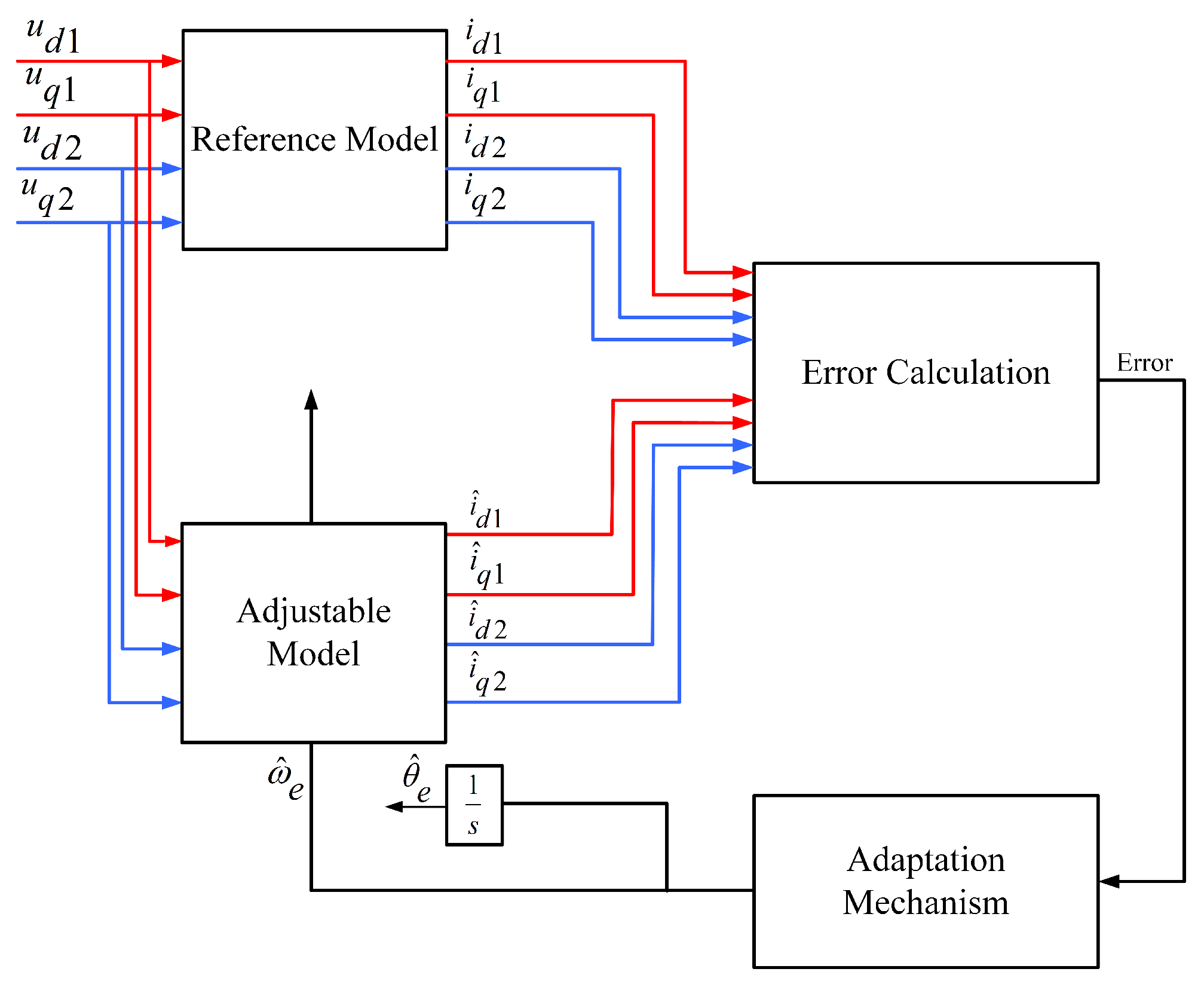
3.2.2. Model Reference Adaptive System (MRAS)

MRAS typically picks the equation with no parameters as the reference model and the one with parameters as the adjustable equation. Adjustable parameters are estimated by comparing two models’ outputs in an adaptation process. Because of this, the control object’s real output reflects that of the reference model. Great progress is achieved in applying MRAS to the servo motion system using a variety of methods. Effective and physically clear, the MRAS algorithm has been used extensively for sensorless control of an induction motor. Two models are required by the MRAS method: a reference model and an adaptive model. The motor itself may serve as both an adaptive model and a reference model in the mathematical model of the DTP-PMSM. Rotor speed is used as a corrective factor in the adaption process in order to determine the present inaccuracies between two models. This approach can be used by the MRAS control method of three-phase PMSM to control a DTP-PMSM, since it is identical in ( d , q ) subspace to three-phase PMSM [27].
It is critical to accurately determine the rotor position in sensorless control of DTP-PMSMs. In the literature, different starting processes may be categorised into three categories: a predefined rotor position established by correct feeding; open-loop startup; and a specialised algorithm for determining the rotor position at standstill. Because the stator current can be regulated precisely, this approach has the potential to provide the highest level of rotor positioning precision, while also requiring the least amount of additional complexity in the system. This method’s dependability is affected by the existence of the load torque, whose magnitude might induce a shift between the imposed alignment position and the real one [31,32], as seen in Figure 6. When calculating the stator current of the machine, the MRAS estimator in this scenario utilises two different models. The first model is known as a reference model, whereas the second model is known as an adaptive model. The difference in outputs between these two models is employed to drive an appropriate adaptation mechanism, which in turn yields an estimated rotor speed. A comprehensive MRAS sensorless control system design technique in discrete-time domain for high-speed drives is proposed and discussed in [33,34].

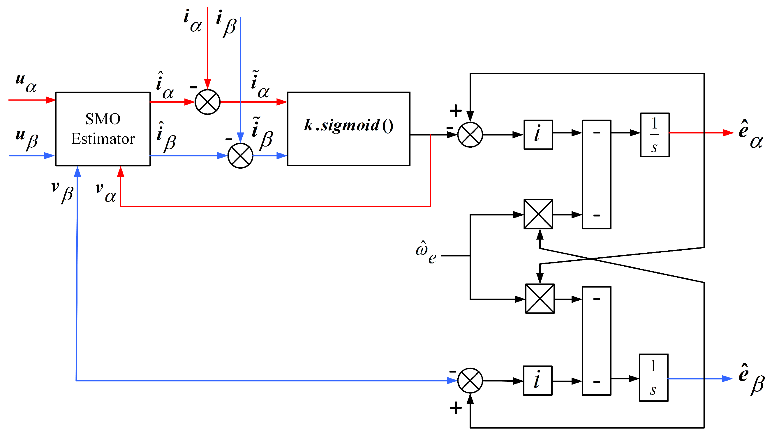
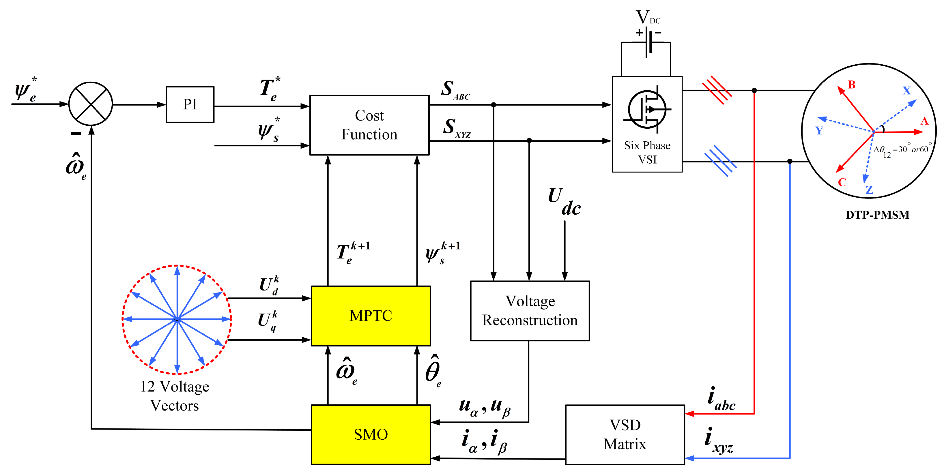
3.2.3. Sliding-Mode Observer

For practical rotor speed/position estimates, the sliding-mode control (SMO) approach is commonly utilised due to its simple methodology and reliability. Although sensorless control of multiphase machines is not a new issue and has been researched for decades, some researchers have attempted to fill in the study gaps for DTP-PMSM. A sign function is often employed to adjust for discontinuous gains. The estimation error reaches a specified surface and then glides along this surface, eventually reaching zero. Chattering is an undesired side effect of discontinuous functions like the sign function. As a result, modifications to reduce the chattering effect have been suggested. A sigmoid function, as shown in Figure 7, for example, may alter the sign function. In some situations, a low-pass filter (LPF) can be used to get rid of the signal’s high frequencies. The LC filter, on the other hand, will introduce a new kind of resonance issue [35].
As a result of using an LC filter, the resonance in the capacitor circuit must be suppressed using an extra resistor. Since the motor resistance is relatively high, adding resistance will cause insignificant losses. It is necessary to incorporate an extra current feedback loop in order to effectively suppress the resonance without causing more damage. Hence, the LPF is removed and replaced with two synchronous frequency-tracking filters (SFTFs), which can extract the fundamental wave component from the back-EMF. This enhances conventional sensorless control.
It is possible to use SMO in order to estimate the rotor position and speed of the DTP-PMSM. Rotor position information can be found in the extended EMF. To obtain the estimated rotor position, the extended EMF must be estimated first. The DTP-PMSM is subjected to a variety of SMO techniques, such as the conventional SMO method and the adoptive SMO method, which are shown in Figure 7 and Figure 8, respectively. The Arctan function and PLL-based estimators are used to estimate the rotor’s speed and position after obtaining an estimated extended EMF [36,37].
A model predictive torque control system is described in [35], and it is constructed using the mathematical model of DTP-PMSM with vector space decoupling (VSD). For the purpose of obtaining the speed, a model predictive torque control approach has been suggested, as shown in Figure 9. In order to reduce the design cost and enhance the anti-interference ability of the system, an SMO strategy is suggested in [35] to estimate the motor speed. This method would include extended rotor resistance compensation, which would increase the system’s resilience. The findings of the simulation indicate that the suggested control system has a rapid dynamic reaction and a high degree of resilience.

3.2.4. Luenberger Observer

A nonlinear gain-correction term is included in this kind of observer, which uses the prediction term to copy the EMF’s dynamic equations. The estimated error converges to zero when the nonlinear observer gain is constructed as recommended in those works, assuming an accurate model, i.e., the parameters in the prediction terms match the parameters in the motor and there is no uncertainty in the measured variable. The key benefit is that convergence is ensured across a large area of state space. Furthermore, the rate of convergence can also be adjusted.
In [38], there is a comparison between two back-EMF based sensorless control techniques, one of them using a phase-locked loop (PLL) speed and rotor position estimator, and the other a Luenberger observer estimator. In the mentioned article, improved dynamic performance is provided by a Luenberger-type estimator. It is stated that the predicted speed error suffers from high-frequency noise and the usage of machine characteristics is required. The PLL-type estimators, on the other hand, have a lower but still adequate level of performance. Low-pass filtering eliminates high-frequency interference. In addition, the PLL type does not involve the usage of any kind of mechanical data.
As a result of the PLL’s simple construction and mechanical independence, it is favoured for future investigation and prospective applications. The rotor speed and position can alternatively be estimated using a Luenberger observer-type speed and position estimator, as illustrated in Figure 10. An observer-type position estimator’s transfer function can then be described in this way, as by [38]:
θ ^ e θ e = J K a s 2 + ( B K a + K b ) s + K c J s 3 + ( J K a + B ) s 2 + ( B K a + K b ) s + K c
where J is rotational inertia and B is viscous friction.
By adjusting the gains of the estimator shown in Figure 10, roots of the characteristic equation in (15) can be forced to coincide with those in the following expressions [38]:
K a = α , K b = j α 2 , K c = J α 3
where α is the root of the characteristic equation.
Table 2 provides an explanation of the benefits and drawbacks of the observers that are used in DTP-PMSM.

4. Saliency-Based Sensorless Control Methods

For zero- and low-speed operating condition, model-based techniques cannot be employed due to the lack of back-EMF. In contrast, saliency-based techniques are able to overcome this limitation and can accurately estimate the rotor position in the zero- and low-speed operating range. These strategies are used as a result of either geometric rotor saliency or magnetic saturation. Saliency-based approaches include PWM signal injection (SI), transient voltage vector injection, and other techniques. Rotating–pulsating sinusoidal SI in the estimated reference frame, and sinusoidal SI in a stationary reference frame are the most common ways of persistent carrier SI.

4.1. SI-Based Systems

Carrier SI-based sensorless control systems typically inject either high-frequency current or voltage signals into the basic excitation windings of the machine. Then the rotor position information is extracted from the position-dependent carrier signal, viz., carrier current or zero-sequence voltage. For the rotating carrier signal-injection method, it has been proven that both negative-sequence carrier current signal and zero-sequence carrier voltage signal can be used to estimate the rotor position. For DTP-PMSM drives, SI-based sensorless control is the most common method used to obtain the position by monitoring the saliency in the low-speed area. The voltage drop on the stator resistance can be omitted, as can the terms associated with ω e , since the injection frequency is much greater than the operating speed [39,40]. Figure 11 presents a sensorless control scheme with high-frequency (HF) SI. The zero-sequence carrier voltage exhibits low total harmonic distortion and shows less sensitivity to the distortion of the injected carrier signal compared to the carrier’s current response. Furthermore, it has been found that the estimation accuracy of the the system bandwidth and rotor position can be enhanced significantly when utilising a zero-sequence carrier voltage.

4.1.1. Voltage Injection

Voltage injection combines the large bandwidth of the zero-sequence voltage method with the high precision of the pulsating injection strategy for estimating position, as shown in Figure 12 and Figure 13. Due to undesired harmonic components in the zero-sequence carrier voltage, the position-estimation error of a single three-phase PMSM is considerable, and the current compensating solutions often require complicated designs or extensive offline measurements. With two separate high-frequency injections into each stator winding set, DTP-PMSM with separated neutral points offers more degrees of freedom. It is possible to alter the phase angle between the two injected high-frequency signals, allowing for the resolution of this problem. When the pulsating carrier signal is injected into the estimated d q synchronous reference frame as two superimposed rotating carrier voltages with opposing directions, the injected voltages for the three phases are as follows:
v a = V c c o s ( ω c t ) c o s ( θ e ^ ) v b = V c c o s ( ω c t ) c o s ( θ e ^ 2 π / 3 ) v c = V c c o s ( ω c t ) c o s ( θ e ^ + 2 π / 3 )
θ e ^ = estimated rotor position
V c = carrier voltage
ω c = carrier frequency
Figure 12. HF d-axis pulsating voltage for the signal injection [41].
Energies 16 01326 g012
Figure 13. Block diagram of zero-sequence carrier signal process with rotating injection [42].
Energies 16 01326 g013
Figure 12 illustrates the pulsating injection that may be seen in the estimated reference frame.
In DTP-PMSM drives, the harmonic components may be reduced by using a modified pulsating injection approach with zero-sequence voltage, which applies an optimal phase shift between the two injected HF carrier signals. According to [41,42,43], these strategies work well for DTP-PMSM. It has also been stated that a novel technique of measuring zero-sequence voltage utilising just one voltage sensor has been developed. Injecting HF voltage into dual three-phase may be accomplished in other ways as well. For instance, HF voltages with the same amplitude and frequency are injected into both three-phase sets in the same spatial direction (parallel injection method), or HF voltages with the same amplitude and frequency are injected into both three-phase sets in opposing directions (opposing injection method).
An HF voltage injection method for determining position is described in [44]. One of the known disadvantages of high-frequency voltage injection is the acoustic noise that is generated. However, the acoustic noise can be minimised by utilising this injection technique only at specific frequencies. The resultant zero-sequence carrier voltage is typically measured by utilising one of the two most used measurement methods, namely (1) measurement utilising phase-to-neutral-voltages, as shown in Figure 14a, or (2) measurement utilising the auxiliary resistor network, as shown in Figure 14b.

4.1.2. Current Injection

It is possible to obtain information about the position and degree of saliency of a salient machine by injecting a carrier signal current into the machine and then measuring the resulting voltages. A comparison for the use of voltage and current injection techniques for the estimation of flux angle or rotor position are included in [45]. In [45], two problems of carrier signal current injection are offered to a basis for fair comparison: the first is the extraction of the spatial information contained in the induced voltages, and the second is the regulation of high-frequency currents with current regulators of limited bandwidth. Based on this comparison, choosing which method to use depends on the application, the desired performance, and the bandwidth of fundamental current regulator. Predominantly, higher performance (higher bandwidth) is possible with carrier signal voltage injection, since the current regulator does not directly limit its bandwidth.
As a parameter identification and position sensorless control approach for motor drives, VSI nonlinearity compensation is critical. For DTP-PMSM drives, an online estimate and compensation approach for VSI nonlinearity has been suggested in [46]. To determine the magnitude of error voltages due to VSI nonlinearity, this approach utilizes voltage differences with z 1 z 2 -axis current injection as its input. An improved recursive least-square (RLS) algorithm and a current injection-based parameter estimation method for DTP-PMSM, considering inverter nonlinearity and magnetic saturation, are proposed in [47].

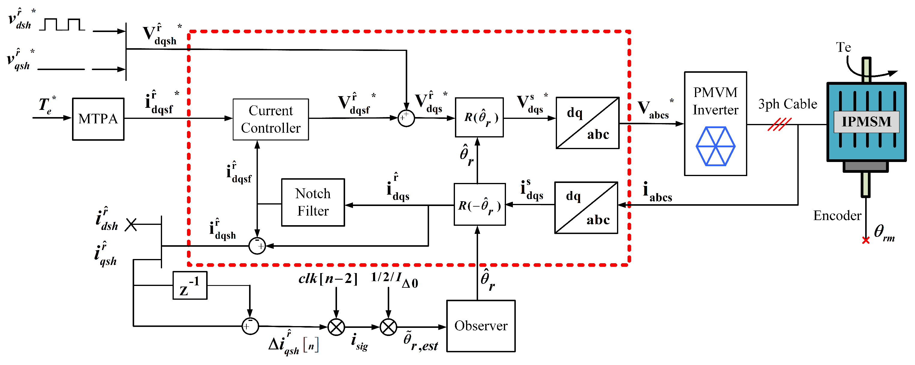
4.2. Pulsating Signal Injection

Using pulsating signal injection as a sensorless control method is another viable option. In order for pulsating signal injection to work, the rotor reference frame must be known from the beginning. Pulsating signal injection can be split into two groups, based on the types of signals that are injected: pulsating square-wave injection and pulsating sinusoidal injection [48].

Square-Wave Sensorless Injection

Half-switching frequency signal-injection sensorless control (SISC) and switching-frequency SISC are the two types of SISCs with fast dynamic characteristics. Ideally, their dynamic properties should resemble one another. If the frequency of the injected voltage signal would increase to pulse-width modulation (PWM) switching frequency and if the switching frequency is near or above an audible range, the dynamics of the sensorless control can be improved, and the acoustic noise can be remarkably reduced or totally eliminated [49]. Switching-frequency SISC, on the other hand, is more susceptible to inverter nonlinearity effects than half-switching-frequency SISC. Switching-frequency injection adds first- and third-order harmonic distortion to position estimation [50]. When it comes to SISC, this means that the greatest possible frequency is half the switching frequency. The block diagram of the conventional SISC is represented in Figure 15. For DTP-PMSM, SISC could be applied in the two three-phase windings individually [51].

4.3. Fundamental PWM Excitation

The fundamental PWM excitation technique has been refined by various researchers in order to make it easier to analyse the results. For instance, using the transient response of the line current to basic PWM vectors, a sensorless algorithm is created in a two-dimensional orthogonal frame, as shown as Figure 16. For multiphase machines, this strategy is ideal [19,52]. Table 3 provides an explanation of the benefits and drawbacks of the saliency-based methods that are used in DTP-PMSM.

5. Combination of Low-Speed and High-Speed Methods

As mentioned previously, an EMF-based observer operates well at medium and high speeds, but a saliency-based observer excels only at low speeds. Therefore, it would appear logical to combine the two approaches in order to obtain an estimator that performs well over the whole speed range. As a result of this, several researchers have developed observers that combine two distinct methods from those described in the previous paragraphs, namely model-based and saliency-based. For instance, for DTP-PMSM, the integration of high-frequency SI and extended EMF-based techniques for sensorless control, or injecting current signal and an EMF estimator, have been proposed [25,53,54]. In Figure 17, an overall block diagram of the DTP-PMSMs control system with a combination of methods is illustrated. Very few studies have been conducted in this area for DTP-PMSM drives, which might be a promising area for future study.

6. Fault-Tolerant Sensorless Control for DTP-PMSMs

DTP-PMSMs have intrinsic fault-tolerant capability due to the physical separation between the phase windings. In this regard, controlling a fault-tolerant DTP-PMSM system without sensors at high and low speeds has been the subject of recent studies [39]. In [55], a fault-tolerant sensorless speed control strategy is discussed for the case of an open-phase fault. The speed control strategy of [55] is realised through a redundant extended back-EMF observer structure for an asymmetrical DTP-PMSM. In [56,57], a new sensorless control is proposed without requiring coordinate transformation by injecting the HF signal into two non-fault phase windings for a six-phase fault-tolerant PMSM. This control method can guarantee the low-speed sensorless control performance under both fault-free and fault-tolerant operation conditions.

7. Applications and Applied Sensorless Control Techniques of DTP-PMSMs

In Table 4, the details of the applications, power levels, and applied sensorless control techniques of DTP-PMSMs from the literature are listed. The table shows that DTP-PMSMs with sensorless control have many industrial applications. Although some of the research focuses on high-power applications, the experimental implementation and evaluation have been limited to low-power levels. Additionally, some researchers are attempting to employ combination methods.

8. Conclusions

This paper has conducted a review of sensorless control of dual three-phase PMSMs (DTP-PMSMs). Sensor-free control is a major area of interest in DTP-PMSM. Sensorless control is superior to sensor-based control when it comes to overall system reliability and cost. Multiphase drives have also attracted the interest of academics and industry over the last three decades. A variety of rotor-position and speed-estimate algorithms have been discussed in the literature, with the aim of determining the most appropriate control approach for use in applications such as ship propulsion, wind turbines, and aerospace, to mention just a few. Based on the research reviewed in this article, there are areas for potential research and development:
  • Some applications, such as aircraft, need an ultra-fast, sensorless DTP-PMSM drive; however, researchers are now faced with the difficulty of figuring out how to acquire the position information under low carrier ratios.
  • Improving the dynamic performance of position sensorless drives for DTP-PMSM is difficult in comparison to motor drives that include a position sensor. It is envisaged that there will be a greater focus on optimising dynamic sensorless performance for use in high-performance applications in the future.
  • PMSM characteristics are known to fluctuate significantly with load changes. It therefore is necessary to improve the robustness of the sensorless PMSM drives to machine parameter fluctuation in order to acquire the rotor position accurately across a broad range of loads.
  • For preferable performance, a combination of two or more techniques is beneficial for estimating the rotor position. Very few studies have been conducted on this for DTP-PMSMs, which might be a promising area for future study.
  • In order to further strengthen the power density and the reliability of the electric actuating system, a sensorless control strategy for fault-tolerant operation (e.g., losing one set of three-phase windings) of DTP-PMSM is important. From the literature reviewed in this article, there are few publications that explain how to control the fault-tolerant operation of DTP-PMSM without sensors at both high and low speeds, which could be an interesting topic for research in the future.

Author Contributions

Conceptualisation, V.T., M.K. and R.-J.W.; methodology, V.T. and M.K.; software, V.T.; validation, V.T., M.K. and R.-J.W.; formal analysis, V.T. and M.K.; investigation, V.T., M.K. and R.K.; writing—original draft preparation, V.T.; writing—review and editing, V.T., M.K., R.-J.W. and R.K.; visualisation, V.T.; supervision, M.K. and R.-J.W.; funding acquisition, R.-J.W. All authors have read and agreed to the published version of the manuscript.

Funding

This research received no external funding.

Institutional Review Board Statement

Not applicable.

Informed Consent Statement

Not applicable.

Data Availability Statement

The data for this study is presently archived with the first author, V.T., and can be made available.

Conflicts of Interest

The authors declare no conflict of interest.

List of Symbols

SymbolsDescriptionSymbolsDescription
R s stator resistancesderivative
ω e electrical angular speed ω c carrier frequency
ψ f , ψ f d permanent magnet flux linkage ψ flux linkage
u d 1 , u q 1 voltages of the first winding setu, ivoltage, current
i d 1 , i q 1 currents of the first winding set θ e electrical rotor position in radians
u d 2 , u q 2 voltages of the second winding set V c carrier voltage
i d 2 , i q 2 currents of the second winding set T e electromagnetic torque
L d , L q d q -axis inductances k p , k i , k d values of the PID controller
M d , M q mutual inductances θ r e , θ e ^ estimated rotor position

References

  1. Alves de Souza, S.; Issamu Suemitsu, W. Five-Phase Permanent-Magnet Synchronous Motor. IEEE Lat. Am. Trans. 2017, 15, 639–645. [Google Scholar] [CrossRef]
  2. Jung, E.; Yoo, H.; Sul, S.K.; Choi, H.S.; Choi, Y.Y. A Nine-Phase Permanent-Magnet Motor Drive System for an Ultrahigh-Speed Elevator. IEEE Trans. Ind. Appl. 2012, 48, 987–995. [Google Scholar] [CrossRef]
  3. Eldeeb, H.M.; Abdel-Khalik, A.S.; Hackl, C.M. Dynamic Modeling of Dual Three-Phase IPMSM Drives With Different Neutral Configurations. IEEE Trans. Ind. Electron. 2019, 66, 141–151. [Google Scholar] [CrossRef]
  4. Teymoori, V.; Eskandaria, N.; Arish, N.; Khalili, A. Design of permanent magnetic motor speed controller drive with power supply inverter based on a new switching method. In Proceedings of the 2019 International Power System Conference (PSC), Tehran, Iran, 9–11 December 2019; pp. 453–458. [Google Scholar] [CrossRef]
  5. Parsa, L.; Toliyat, H. Multi-phase permanent magnet motor drives. In Proceedings of the 38th IAS Annual Meeting on Conference Record of the Industry Applications Conference, Salt Lake City, UT, USA, 12–16 October 2003; Volume 1, pp. 401–408. [Google Scholar] [CrossRef]
  6. Parsa, L.; Toliyat, H.A. Sensorless Direct Torque Control of Five-Phase Interior Permanent-Magnet Motor Drives. IEEE Trans. Ind. Appl. 2007, 43, 952–959. [Google Scholar] [CrossRef]
  7. Pulvirenti, M.; Da Rù, D.; Bianchi, N.; Scarcella, G.; Scelba, G. Secondary saliencies decoupling technique for self-sensing integrated multi-drives. In Proceedings of the 2016 IEEE Symposium on Sensorless Control for Electrical Drives (SLED), Nadi, Fiji, 5–6 June 2016; pp. 1–6. [Google Scholar] [CrossRef]
  8. Arish, N.; Ardestani, M.; Teymoori, V. Comparison of Dual Stator Consequent-pole Linear Permanent Magnet Vernier Machine with Toroidal and Concentrated Winding. In Proceedings of the 2020 11th Power Electronics, Drive Systems, and Technologies Conference (PEDSTC), Tehran, Iran, 4–6 February 2020; pp. 1–5. [Google Scholar] [CrossRef]
  9. Yan, L.; Zhu, Z.Q.; Qi, J.; Ren, Y.; Gan, C.; Brockway, S.; Hilton, C. Suppression of Major Current Harmonics for Dual Three-Phase PMSMs by Virtual Multi Three-Phase Systems. IEEE Trans. Ind. Electron. 2022, 69, 5478–5490. [Google Scholar] [CrossRef]
  10. Slunjski, M.; Dordevic, O.; Jones, M.; Levi, E. Symmetrical/Asymmetrical Winding Reconfiguration in Multiphase Machines. IEEE Access 2020, 8, 12835–12844. [Google Scholar] [CrossRef]
  11. Zhao, Y.; Lipo, T. Space vector PWM control of dual three-phase induction machine using vector space decomposition. IEEE Trans. Ind. Appl. 1995, 31, 1100–1109. [Google Scholar] [CrossRef]
  12. Shao, B.; Zhu, Z.Q.; Feng, J.H.; Guo, S.Y.; Li, Y.F.; Feng, L.; Shuang, B. Improved Direct Torque Control Method for Dual-Three-Phase Permanent-Magnet Synchronous Machines With Back EMF Harmonics. IEEE Trans. Ind. Electron. 2021, 68, 9319–9333. [Google Scholar] [CrossRef]
  13. Zhang, P.; Zhang, W.; Shen, X. Comparative study of Field-Oriented Control in different coordinate systems for DTP-PMSM. In Proceedings of the 2013 International Conference on Electrical Machines and Systems (ICEMS), Busan, Republic of Korea, 26–29 October 2013; pp. 1015–1019. [Google Scholar] [CrossRef]
  14. Singh, S.; Tiwari, A.N. Various techniques of sensorless speed control of PMSM: A review. In Proceedings of the 2017 Second International Conference on Electrical, Computer and Communication Technologies (ICECCT), Coimbatore, India, 22–24 February 2017; pp. 1–6. [Google Scholar] [CrossRef]
  15. Robeischl, E.; Schroedl, M. Optimized INFORM measurement sequence for sensorless PM synchronous motor drives with respect to minimum current distortion. IEEE Trans. Ind. Appl. 2004, 40, 591–598. [Google Scholar] [CrossRef]
  16. Wang, S.; Imai, K.; Doki, S. Analysis of an Application of the Extended Electromotive Force Model Based Position Sensorless Control on the Wound-Field Synchronous Motor with Dual-Three Phases in Standstill/Low Speed Region. In Proceedings of the IECON 2018—44th Annual Conference of the IEEE Industrial Electronics Society, Washington, DC, USA, 21–23 October 2018; pp. 5789–5794. [Google Scholar] [CrossRef]
  17. Wang, G.; Valla, M.; Solsona, J. Position Sensorless Permanent Magnet Synchronous Machine Drives—A Review. IEEE Trans. Ind. Electron. 2020, 67, 5830–5842. [Google Scholar] [CrossRef]
  18. Zhu, Z.; Wang, S.; Shao, B.; Yan, L.; Xu, P.; Ren, Y. Advances in Dual-Three-Phase Permanent Magnet Synchronous Machines and Control Techniques. Energies 2021, 14, 7508. [Google Scholar] [CrossRef]
  19. Ahmad, M.; Zhang, W.; Gao, Q. Low and zero speed position estimation of dual three-phase PMSMs based on the excitation of PWM waveforms. In Proceedings of the 2017 IEEE 3rd International Future Energy Electronics Conference and ECCE Asia (IFEEC 2017—ECCE Asia), Kaohsiung, Taiwan, 3–7 June 2017; pp. 1652–1658. [Google Scholar] [CrossRef]
  20. Hu, Y.; Zhu, Z.Q.; Odavic, M. Comparison of Two-Individual Current Control and Vector Space Decomposition Control for Dual Three-Phase PMSM. IEEE Trans. Ind. Appl. 2017, 53, 4483–4492. [Google Scholar] [CrossRef]
  21. Wang, B.; Wei, G.; Chu, J.; Yi, G. A novel modeling for a dual three-phase permanent magnet synchronous machine. In Proceedings of the 2008 10th International Conference on Control, Automation, Robotics and Vision, Hanoi, Vietnam, 17–20 December 2008; pp. 1630–1634. [Google Scholar] [CrossRef]
  22. Wang, Z.; Chen, J.; Cheng, M.; Ren, N. Vector space decomposition based control of neutral-point-clamping (NPC) three-level inverters fed dual three-phase PMSM drives. In Proceedings of the IECON 2016—42nd Annual Conference of the IEEE Industrial Electronics Society, Florence, Italy, 23–26 October 2016; pp. 2988–2993. [Google Scholar] [CrossRef]
  23. Hu, Y.; Zhu, Z.Q.; Liu, K. Current Control for Dual Three-Phase Permanent Magnet Synchronous Motors Accounting for Current Unbalance and Harmonics. IEEE J. Emerg. Sel. Top. Power Electron. 2014, 2, 272–284. [Google Scholar] [CrossRef] [Green Version]
  24. Imai, K.; Doki, S.; Fujii, K.; Jung, S. Position sensorless control for wound-field synchronous motor with double three-phase wound stator using extended electromotive force model. In Proceedings of the 2018 IEEE International Conference on Industrial Technology (ICIT), Lyon, France, 20–22 February 2018; pp. 492–497. [Google Scholar] [CrossRef]
  25. Liu, T.; Zhu, Z.Q.; Wu, Z.Y.; Stone, D.; Foster, M. A Simple Sensorless Position Error Correction Method for Dual Three-Phase Permanent Magnet Synchronous Machines. IEEE Trans. Energy Convers. 2021, 36, 895–906. [Google Scholar] [CrossRef]
  26. Scelba, G.; Scarcella, G.; Cacciato, M.; Pulvirenti, M.; Testa, A. Compensation of rotor positon estimation errors in sensorless dual-three phase PMSM drives through back-EMF sensing. In Proceedings of the 2017 IEEE International Symposium on Sensorless Control for Electrical Drives (SLED), Catania, Italy, 18–19 September 2017; pp. 199–206. [Google Scholar] [CrossRef]
  27. Liu, J.; Zhu, Z. Rotor position estimation for dual-three-phase permanent magnet synchronous machine based on third harmonic back-EMF. In Proceedings of the 2015 IEEE Symposium on Sensorless Control for Electrical Drives (SLED), Sydney, Australia, 7–8 June 2015; pp. 1–8. [Google Scholar] [CrossRef]
  28. Almarhoon, A.H.; Ren, Y.; Zhu, Z.Q. Sensorless switching-table-based direct torque control for dual three-phase PMSM drives. In Proceedings of the 2014 17th International Conference on Electrical Machines and Systems (ICEMS), Hangzhou, China, 22–25 October 2014; pp. 1616–1621. [Google Scholar] [CrossRef]
  29. Liu, J.; Zhu, Z.Q. Rotor position estimation for single- and dual-three-phase permanent magnet synchronous machines based on third harmonic back-EMF under imbalanced situation. Chin. J. Electr. Eng. 2017, 3, 63–72. [Google Scholar] [CrossRef]
  30. Almarhoon, A.H.; Ren, Y.; Zhu, Z.Q. Influence of back-EMF and current harmonics on sensorless control performance of single and dual three-phase permanent magnet synchronous machines. Compel-Int. J. Comput. Math. Electr. Electron. Eng. 2016, 35, 744–763. [Google Scholar] [CrossRef]
  31. Fan, L.; Yang, T.; Rashed, M.; Bozhko, S. Sensorless control of dual-three phase PMSM based aircraft electric starter/generator system using model reference adaptive system method. In Proceedings of the CSAA/IET International Conference on Aircraft Utility Systems (AUS 2018), Guiyang, China, 19–22 June 2018; pp. 787–794. [Google Scholar] [CrossRef]
  32. He, Y.; Hu, W.; Wang, Y.; Wu, J.; Wang, Z. Speed and Position Sensorless Control for Dual-Three-Phase PMSM Drives. In Proceedings of the 2009 Twenty-Fourth Annual IEEE Applied Power Electronics Conference and Exposition, Washington, DC, USA, 15–19 February 2009; pp. 945–950. [Google Scholar] [CrossRef]
  33. Chen, Y.; Yang, T.; Khowja, M.; La Rocca, A.; Nasir, U.; Chowdhury, S.; Evans, D.; Kember, D.; Klonowski, T.; Arnaud, Y.; et al. Mild hybridisation of turboprop engine with high-power-density integrated electric drives. IEEE Trans. Transp. Electrif. 2022, 8, 4148–4162. [Google Scholar] [CrossRef]
  34. Chen, Y.; Yang, T.; Fan, L.; Bozhko, S. Sensorless Control Design of High-Speed Electric Drives in Discrete Time Domain for Mild-Hybrid Turboprop Aircraft Applications. IEEE Trans. Transp. Electrif. 2022, 1. [Google Scholar] [CrossRef]
  35. Yang, Y.; Song, W.; Ren, H. Encoderless Model Predictive Torque Control of DTP-PMSM with Sliding Mode Speed Observer. In Proceedings of the 2021 IEEE International Conference on Predictive Control of Electrical Drives and Power Electronics (PRECEDE), Jinan, China, 20–22 November 2021; pp. 202–206. [Google Scholar] [CrossRef]
  36. Fan, L.; Yang, T.; Chen, Y.; Bozhko, S. Comparative Study of Sensorless Methods Based on Sliding Mode Observer for Dual Three-Phase Permanent Magnet Synchronous Machine. In Proceedings of the 10th International Conference on Power Electronics, Machines and Drives (PEMD 2020), Online, 15–17 December 2020; pp. 850–854. [Google Scholar] [CrossRef]
  37. Yu, H.; Gan, C.; Wang, H.; Chen, Y.; Ni, K.; Qu, R. Speed Adaptative Sensorless Control Method of a High-speed Dual Three-phase Permanent Magnet Synchronous Motor. In Proceedings of the 2020 23rd International Conference on Electrical Machines and Systems (ICEMS), Hamamatsu, Japan, 24–27 November 2020; pp. 155–160. [Google Scholar] [CrossRef]
  38. Fan, L.; Yang, T.; Rashed, M.; Bozhko, S. Comparative Study Of Back EMF Based Sensorless Control Methods For Dual Three-Phase PMSM. In Proceedings of the 2018 IEEE International Conference on Electrical Systems for Aircraft, Railway, Ship Propulsion and Road Vehicles and International Transportation Electrification Conference (ESARS-ITEC), Nottingham, UK, 7–9 November 2018; pp. 1–6. [Google Scholar] [CrossRef]
  39. Barcaro, M.; Faggion, A.; Bianchi, N.; Bolognani, S. Sensorless Rotor Position Detection Capability of a Dual Three-Phase Fractional-Slot IPM Machine. IEEE Trans. Ind. Appl. 2012, 48, 2068–2078. [Google Scholar] [CrossRef]
  40. Barcaro, M.; Faggion, A.; Bianchi, N.; Bolognani, S. Predicted and experimental anisotropy of a dual three-phase interior permanent magnet motor for sensorless rotor position control. In Proceedings of the 6th IET International Conference on Power Electronics, Machines and Drives (PEMD 2012), Bristol, UK, 27–29 March 2012; pp. 1–6. [Google Scholar] [CrossRef]
  41. Almarhoon, A.H.; Zhu, Z.Q.; Xu, P.L. Improved Pulsating Signal Injection Using Zero-Sequence Carrier Voltage for Sensorless Control of Dual Three-Phase PMSM. IEEE Trans. Energy Convers. 2017, 32, 436–446. [Google Scholar] [CrossRef]
  42. Almarhoon, A.H.; Zhu, Z.Q.; Xu, P. Improved Rotor Position Estimation Accuracy by Rotating Carrier Signal Injection Utilizing Zero-Sequence Carrier Voltage for Dual Three-Phase PMSM. IEEE Trans. Ind. Electron. 2017, 64, 4454–4462. [Google Scholar] [CrossRef]
  43. Wang, K.; Zhang, J.Y.; Gu, Z.Y.; Sun, H.Y.; Zhu, Z.Q. Torque Improvement of Dual Three-Phase Permanent Magnet Machine Using Zero Sequence Components. IEEE Trans. Magn. 2017, 53, 1–4. [Google Scholar] [CrossRef]
  44. Roetzer, M.; Vollmer, U.; Chen, L.; Kennel, R. Anisotropy-based position estimation approach for symmetrical dual three-phase permanent magnet synchronous machines. In Proceedings of the 2017 IEEE International Symposium on Sensorless Control for Electrical Drives (SLED), Catania, Italy, 18–19 September 2017; pp. 157–164. [Google Scholar] [CrossRef]
  45. Ribeiro, L.; Degner, M.; Briz, F.; Lorenz, R. Comparison of carrier signal voltage and current injection for the estimation of flux angle or rotor position. In Proceedings of the Conference Record of 1998 IEEE Industry Applications Conference. Thirty-Third IAS Annual Meeting (Cat. No.98CH36242), St. Louis, MO, USA, 12–15 October 1998; Volume 1, pp. 452–459. [Google Scholar] [CrossRef]
  46. Yu, K.; Wang, Z. An Online Compensation Method of VSI Nonlinearity for Dual Three-Phase PMSM Drives Using Current Injection. IEEE Trans. Power Electron. 2022, 37, 3769–3774. [Google Scholar] [CrossRef]
  47. Li, Z.; Feng, G.; Lai, C.; Banerjee, D.; Li, W.; Kar, N.C. Current Injection-Based Multi-parameter Estimation for Dual Three-Phase IPMSM Considering VSI Nonlinearity. IEEE Trans. Transp. Electrif. 2019, 5, 405–415. [Google Scholar] [CrossRef]
  48. Bin, X.; Luo, X.; Zhu, L.; Zhao, J. Sensorless Control of Dual Three-Phase PMSM with High Frequency Voltage Signal Injection. In Proceedings of the 2019 22nd International Conference on Electrical Machines and Systems (ICEMS), Harbin, China, 11–14 August 2019; pp. 1–4. [Google Scholar] [CrossRef]
  49. Kim, S.; Ha, J.I.; Sul, S.K. PWM Switching Frequency Signal Injection Sensorless Method in IPMSM. IEEE Trans. Ind. Appl. 2012, 48, 1576–1587. [Google Scholar] [CrossRef]
  50. Hwang, C.E.; Lee, Y.; Sul, S.K. Analysis on Position Estimation Error in Position-Sensorless Operation of IPMSM Using Pulsating Square Wave Signal Injection. IEEE Trans. Ind. Appl. 2019, 55, 458–470. [Google Scholar] [CrossRef]
  51. Lee, Y.R.; Yoo, J.; Sul, S.K. Switching Frequency Signal-Injection Sensorless Control Robust to Non-Ideal Characteristics of Inverter System for Dual Three-Phase PMSM. In Proceedings of the 2021 IEEE Energy Conversion Congress and Exposition (ECCE), Vancouver, BC, Canada, 10–14 October 2021; pp. 4761–4768. [Google Scholar] [CrossRef]
  52. Chen, H.; Gao, Q.; Zhu, H. Low and zero speed sensorless control of dual three-phase permanent magnet synchronous machines using the fundamental PWM excitation. In Proceedings of the 10th International Conference on Power Electronics, Machines and Drives (PEMD 2020), Online, 15–17 December 2020; Volume 2020, pp. 152–157. [Google Scholar] [CrossRef]
  53. Liu, T.; Zhu, Z.Q.; Wu, X.; Wu, Z.; Stone, D.A.; Foster, M.P. A Position Error Correction Method for Sensorless Control of Dual Three-Phase Permanent Magnet Synchronous Machines. IEEE Trans. Ind. Appl. 2022, 58, 3589–3601. [Google Scholar] [CrossRef]
  54. Liu, T.; Zhu, Z.; Wu, X.; Wu, Z.; Stone, D.; Foster, M. A Position Error Correction Method for Sensorless Control of Dual Three-Phase Permanent Magnet Synchronous Machines. In Proceedings of the 2021 IEEE International Electric Machines and Drives Conference (IEMDC), Hartford, CT, USA, 17–20 May 2021; pp. 1–7. [Google Scholar] [CrossRef]
  55. Furmanik, M.; Scelba, G.; Rafajdus, P. Fault-Tolerant Sensorless Control for Six-Phase PMSM with Dual Back-EMF Observer. In Proceedings of the 2022 International Symposium on Power Electronics, Electrical Drives, Automation and Motion (SPEEDAM), Sorrento, Italy, 22–24 June 2022; pp. 305–311. [Google Scholar] [CrossRef]
  56. Fang, H.; Xu, J.; Du, Y. A Novel High Frequency Signal Injection Based Sensorless Control Method for Six-Phase FTPMSM System. In Proceedings of the 2019 22nd International Conference on Electrical Machines and Systems (ICEMS), Harbin, China, 11–14 August 2019; pp. 1–6. [Google Scholar] [CrossRef]
  57. Xu, J.; Fang, H.; Liang, Z.; Zhang, B.; Guo, H. Sensorless Fault-Tolerant Control via High-Frequency Signal Injection for Aerospace FTPMSM Drives With Phase Open- and Short-Circuit Faults. IEEE Trans. Transp. Electrif. 2022, 8, 3401–3410. [Google Scholar] [CrossRef]
  58. Qiu, X.; Ji, J.; Zhou, D.; Zhao, W.; Chen, Y.; Huang, L. A Modified Flux Observer for Sensorless Direct Torque Control of Dual Three-Phase PMSM Considering Open-Circuit Fault. IEEE Trans. Power Electron. 2022, 37, 15356–15369. [Google Scholar] [CrossRef]
Figure 1. Arrangement of winding in DTP-Machine: (a) asymmetrical; (b) symmetrical.
Energies 16 01326 g001
Figure 2. Voltage source inverter-fed DTP-PMSM drive with stator winding connection. (a) single neutral topology; (b) two isolated neutrals topology [11].
Energies 16 01326 g002
Figure 3. (a) Historical development of sensorless control for multiphase and DTP-PMSM drives; (b) classification of sensorless control.
Energies 16 01326 g003
Figure 4. Block diagram of all methods for the control and estimation of position and speed.
Energies 16 01326 g004
Figure 5. EKF-based rotor position estimator for DTP Machines [27].
Energies 16 01326 g005
Figure 6. Block diagram of MRAS [31].
Energies 16 01326 g006
Figure 7. Block diagram of conventional SMO method [36].
Energies 16 01326 g007
Figure 8. Block diagram of adaptive SMO method [36].
Energies 16 01326 g008
Figure 9. Model predictive torque control system [35].
Energies 16 01326 g009
Figure 10. Block diagram of Luenberger observer-based speed and position estimator [38].
Energies 16 01326 g010
Figure 11. Sensorless control scheme with HF signal injection [39].
Energies 16 01326 g011
Figure 14. (a) Measurement of zero-sequence voltage using phase-to-neutral voltages. (b) Measurement of zero-sequence voltage using auxiliary resistor network [41].
Energies 16 01326 g014
Figure 15. Block diagram of conventional square-wave injection sensorless drive system [51].
Energies 16 01326 g015
Figure 16. Voltage vector map in stationary frame. (a) Projection of voltages on α β plane. (b) Projection of voltages on z 1 z 2 plane [19].
Energies 16 01326 g016
Figure 17. Overall block diagram of DTP-PMSMs control system with combination methods [54].
Energies 16 01326 g017
Table 1. Advantages and disadvantages of VSD and MITP models.
MethodAdvantagesDisadvantages
VSD
-
Separated and simpler models in several subspaces.
-
Improved simplicity in the controller design.
-
A simpler approach for controlling harmonics.
-
Less equipped to cope with imbalance due to the asymmetry of the sets.
-
Requires more effort to establish active power and torque sharing.
MITP
-
Forthright.
-
Three-phase set design as well as control modularisation.
-
Increased interconnectivity between sets.
-
As the number of sets rises, so does the level of model and control sophistication.
Table 2. Comparison of position observers.
TypesEKFMRASSMOLuenberger
AdvantagesLess influence of noise;
low computational
time
A fail-safe machine
model; high-velocity
adaptation
Guaranteeing no
mistakes; very reliable;
independent of motor
parameters
Convergence is certain
all across a large chunk
of the possible states;
convergence times are
completely arbitrary
DisadvantagesWeak low-speed
performance
Struggle with a wide
range of motor
characteristics
Ineffective at rest and
at slow speeds
Can make the sensor
noise issue much worse
Table 3. Comparison of saliency-based methods.
TypesVoltage
Injection
Current
Injection
Pulsating Signal
Injection
Fumdamental PWM
Excitiation
AdvantagesNo acoustic noise;
independent of
motor parameter
High performance;
independent of
motor parameter
Small effect on inverter
nonlinierities;
magnetude modulated
Insensetive to
parameter variation
DisadvatageDo not support high
speed operation

High computational
requirement, which
needs powerful
hardware devices
Requiring initial
position information
High current ripple;
flux distortion causes
estimation error
Table 4. Application and power levels of sensorless control of DTP-PMSM.
Power levelTechniquesApplicationReference
50 WSaliency-based (Signal Injection)Aerospaces[57]
170 WModel-based (EKF)High power and high current[28]
170 WModel-based (EKF)Industrial applications[28]
170 WSaliency-based (Signal Injection)High power and high current[41]
170 WSaliency-based (Voltage injection)High power and high current[42]
230 WModel-based (EKF)Power applications, high speed[27,29]
230 WSaliency-based (Signal Injection)Power applications[45]
500 WSaliency-based (Signal Injection)Low speed applications[48]
1 kWModel-based (Luenberger)Electric vehicles[55]
2.3 kWBack EMFIndustrial applications[9]
3 kWModel-based (MRAS)Industrial applications[32]
3.7 kWCombination methodPower applications[25]
4.2 kWModel-based (Luenberger)Small and medium machines[26]
4.5 kWSaliency-based (Current Injection)Special applications in aircraft drives, Automotive tractions, and electric ship propulsions[47]
5 kWSaliency-based (FPE)Low- and zero-speeds applications[19]
5.5 kWModel-based (SMO)Military applications[35]
6.7 kWModel-based (Back EMF)High-speed applications[58]
20 kWModel-based (MRAS)Aircraft and high-speed applications[33]
240 WCurrent controlHigh-power industrial applications[23]
200 WModel-basedElectric vehicles[24]
UndefinedSignal injectionIndustrial applications[39]
UndefinedSaliency-based (FPE)Low speed applications[52]
UndefinedCombination methodHigh-power applications[53,54]
Disclaimer/Publisher’s Note: The statements, opinions and data contained in all publications are solely those of the individual author(s) and contributor(s) and not of MDPI and/or the editor(s). MDPI and/or the editor(s) disclaim responsibility for any injury to people or property resulting from any ideas, methods, instructions or products referred to in the content.

