Article

Eddy Current Loss Reduction in Axial-Flux Motors Using 3D Printing †

1
Department of Electrical Engineering, Gachon University, Seongnam 13120, Republic of Korea
2
Department of Electrical and Computer Engineering, Michigan State University, East Lansing, MI 48824, USA
*
Author to whom correspondence should be addressed.
This paper is an extended version of our paper published in 2020 IEEE Energy Conversion Congress and Exposition (ECCE), Detroit, MI, USA, 11–15 October 2020.
Energies 2023, 16(3), 1318; https://doi.org/10.3390/en16031318
Submission received: 11 November 2022 / Revised: 10 January 2023 / Accepted: 12 January 2023 / Published: 26 January 2023
(This article belongs to the Special Issue Advanced Electrical Machine Design and Optimization)

Abstract

:
As more electrification and emission-free transportation trends receive more attention, electrical systems applied in the aircraft and automotive industries are changing from fossil fuel and hydraulic systems to electric AC machine drive systems. Three-dimensional printing technology has been contributing to a new design of machines, because it provides many opportunities without limitation compared to the conventional manufacturing system. Although 3D printing technology opened a door for increasing the efficiency and power density of AC machine drives with low conduction loss, an optimal design process for eddy current loss reduction is required, because eddy current loss is affected by the design structure of the machine. The slit structure at the stator shoe is proposed to reduce eddy current loss. With the three variables, the number of slits, the thickness of slits, and the length of ribs, a parametric analysis was conducted to find an optimal design with eddy current loss reduction without a significant performance dip. The optimal design provides an 18.75% decrease in eddy current loss.

1. Introduction

As more electrification and emission-free transportation trends receive more attention, electrical systems applied in the aircraft and automotive industries are changing from fossil fuel and hydraulic systems to electric AC machine drive systems. Due to the skyrocketing demand for electric AC machine drive systems, high-efficiency and high-power-density AC machine drives are required. Most AC machine drive systems applied to aircraft, automotive, and industry are built with permanent magnet and induction machines. Induction motors (IM) have been widely used in industry and propulsion systems applied in aircrafts [1,2,3]. It has also been indicated that a water pump, considered a heart part of the irrigation system, has been built with IM. There are several advantages when IM is used in AC machine drives. The lower cost and lower maintenance issues compared to other types of machines are the major advantages of AC machine drives. However, these advantages can be diminished due to high inrush currents and voltage dips when the IM starts rotating [4,5,6]. Interior permanent magnet synchronous machines (IPMSM) have been used in automotive propulsion systems. Although IPMSM provides high efficiency and power density compared to IM-based AC machine drives, it is not well fitted for most electrical systems because of the high and fluctuating costs of rare earth magnets [7,8,9].
Moreover, axial-flux permanent magnet synchronous machines (AFPMSM) are also commonly used in various applications. There are validated advantages, such as high power density, torque-to-weight ratio, and geometrically higher aspect ratio, compared to radial-flux permanent magnet synchronous motors (RFPMSMs) [10,11,12]. As AFPMSMs are receiving more attention because of these advantages, several effective topologies have been proposed. For example, a two-layer AFPMSM was proposed in [13] to obtain higher power and torque density. Furthermore, a new spoke-type AFPMSM coreless disk motor with dual rotors and a single stator was proposed in [14] to compensate for lowered air-gap flux density without the core. The coreless structure opened the door for increasing the efficiency and power density of AC machine drives with low conduction loss. However, the coreless structure requires bonding methods to keep the stiffness for rotating because there is no core [15]. Therefore, a 3D-printed hybrid AFPMSM has been proposed to increase efficiency and power density to keep high efficiency and power density with the core [16]. It leads to a major advantage that the stator and rotor structures can be built without any limitations. Although the machines cannot have various structures using the conventional manufacturing system because the core is laminated with steel sheets and is made by the metal stamping process, the structure, which cannot be made using the conventional manufacturing system, can be made with 3D printing technology.
Core loss has two categories: hysteresis and eddy current loss. Although hysteresis loss is affected by the core material specification, eddy current loss has various spectra because it is affected by the core structure. Since the core material is selected by 3D printing technology, comprehensive eddy current loss analysis is required when 3D printing technology is used. This paper proposes a novel AFPMSM with slits on the surface of the stator, which reduce the total path length of the eddy current, to decrease eddy current loss while the performance of the proposed AFPMSM is maintained. A parametric analysis is conducted to find an optimal AFPMSM. Then, a comparative eddy current loss and performance analysis is conducted to validate that the proposed AFPMSM meets the requirements.
This paper is organized as follows: Section 2 will introduce the principle of 3D printing technology, including comprehensive core loss analysis based on various materials. A novel material, which is used for the proposed AFPMSM, will be proposed in Section 2. The proposed AFPMSM structure will be presented using the material in Section 3. A parametric analysis will be presented to find an optimal model which has decreased eddy current loss and meets the performance requirement in Section 4. Finally, the conclusion will be drawn in Section 5.

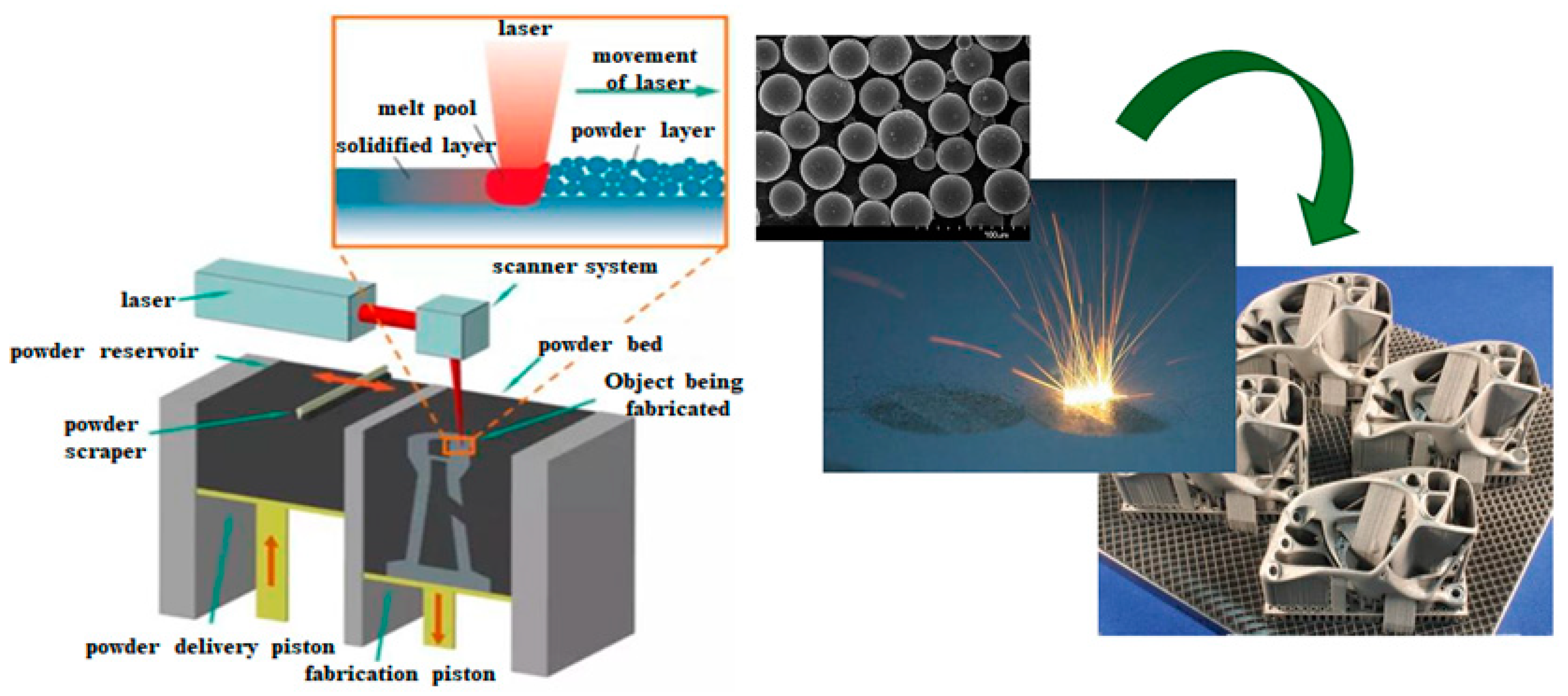
2. Principle of 3D Printing Technology

2.1. Process of 3D Printing

The 3D-printed SMC materials can be manufactured using the multiple-scan strategy, which induces homogeneous distribution of the constituent elements to ensure stable formation, compared to existing soft magnetic composite (SMC) materials. This advantage is from the scanning strategy on phase formation and microstructure. Although the conventional scanning strategy makes the laser energy unevenly distributed across the object layer, a novel scanning strategy, named selective laser melting (SLM) technique, using a multiple-scan electron probe X-ray microanalyzer (EPMA), leads to averaged melt flow, and the averaged melt flow induces better uniformity of the constituent elements [17]. Furthermore, selective laser melting fabricates computer-aided design (CAD) in a layer-wise manner by selectively melting deposited powders, as shown in Figure 1 [16]. This technique confirms that a high-quality desired structure can be produced using 3D-printed SMC materials. This paper only considers the 3D printing technology and the SLM technique using the EPMA device.
It is possible to create a structure of stator and rotor, when an AFPMSM is built via the 3D printing technology explained above, that could not have been designed via the conventional manufacturing system. Using the SLM technique, high-density compacts can be fabricated based on the melting solidification principle and rapid quenching process. It leads to complicated 3D structures, thereby the structures affect high efficiency and power density as prior studies validated in [18,19,20,21].

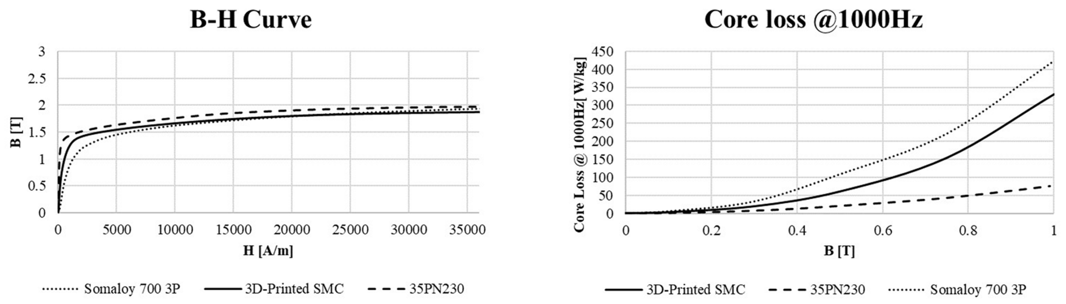
2.2. Comprehensive Core Loss Comparison of Three Materials

SMC materials are commonly used to reduce the eddy current losses in the existing AFPMSMs. Since each particle is insulated, the eddy current loss is reduced when SMC materials are used as validated in [22,23,24,25]. However, the advantage of the SMC materials is mitigated because the SLM technique is used. To find an optimal material, a parametric analysis was conducted. The B–H curve and core loss data comparison between the existing SMC material, named Somaloy 700 3P, electrical steel plate, named 35PN203, and 3D-printed SMC material is presented in Figure 2.
According to the B–H curve, the 3D-printed SMC material presented by the blue line shows higher performance than the existing SMC material presented by the green line, as shown in Figure 2 left. However, the core loss graph indicates that the core loss of the 3D-printed SMC material presented by the blue line is higher than that of the electrical steel plate presented by the red line, as shown in Figure 2 right. Since the eddy current loss increases when the motor is built with the 3D printing technology because the particle insulation melts based on the result of the B-H curve and core loss analysis, a laminated structure, which is widely applied in radial-flux permanent magnet synchronous machines (RFPMSMs), is applied to the AFPMSM to reduce the eddy current loss while the advantage of 3D printing technology is maintained. The details will be presented in Section 3.

3. Core Loss Analysis Using 3D Printing Technology

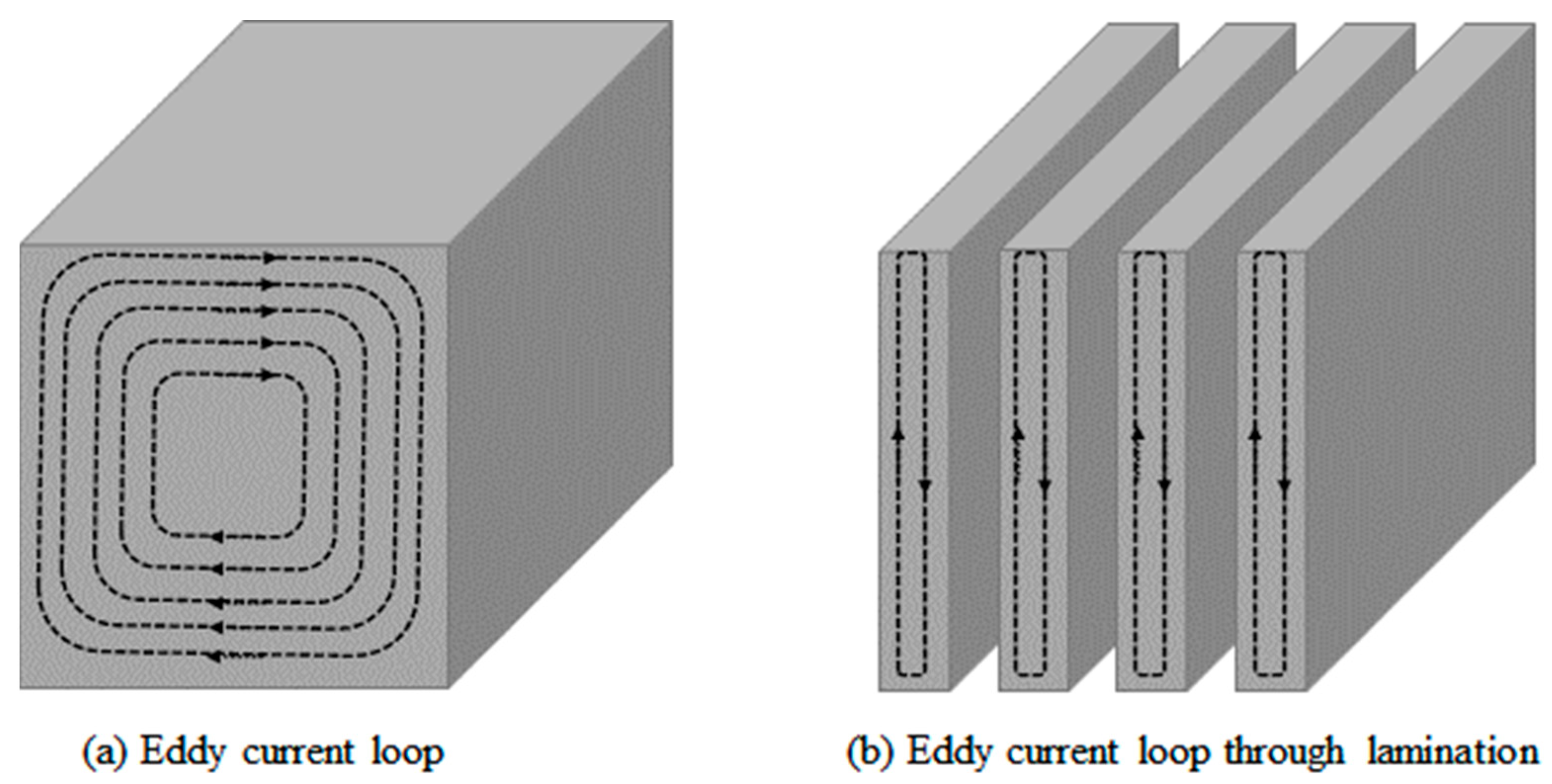
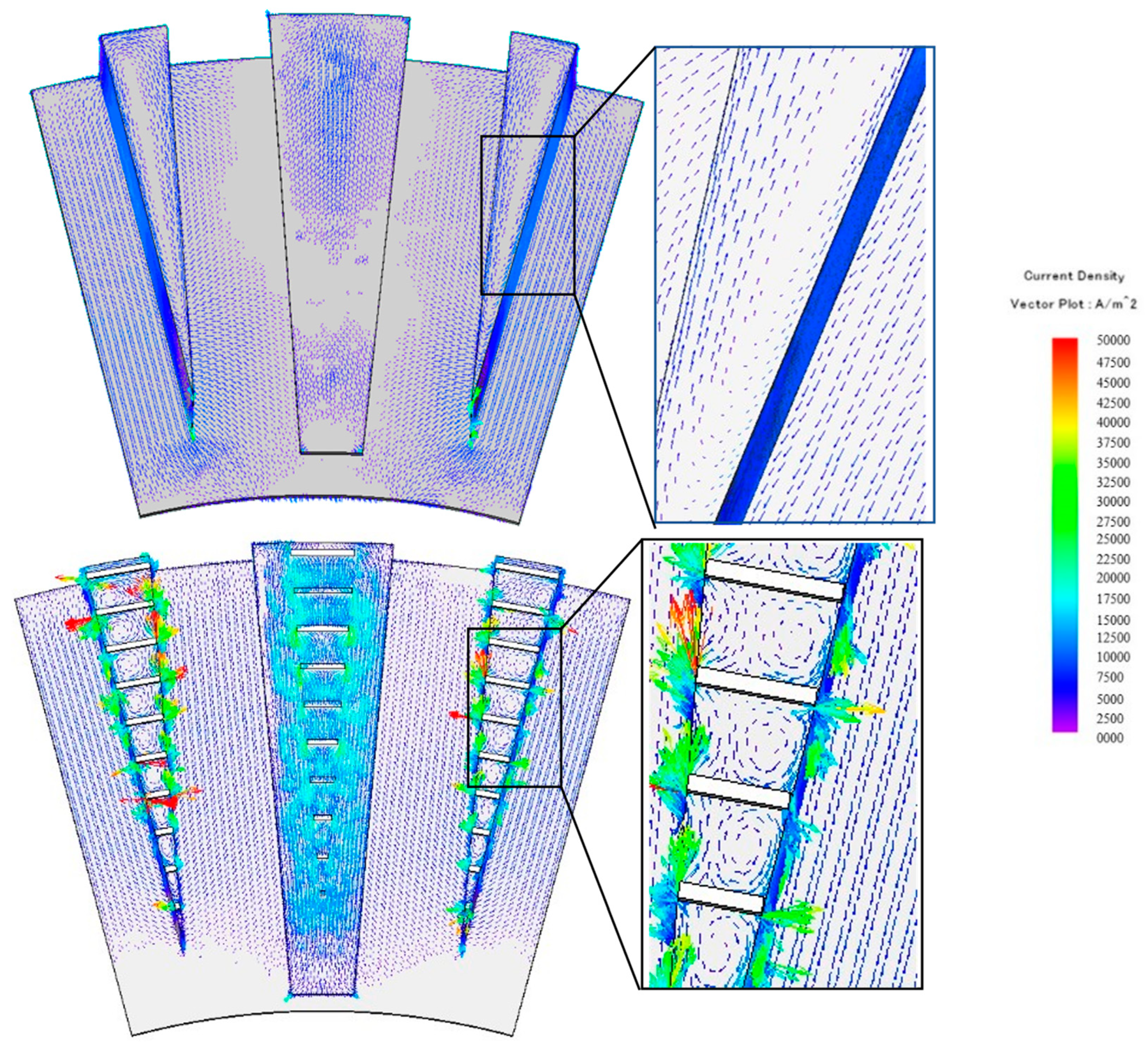
3.1. Principle of Eddy Current Loss

As the laminated structure is used in AFPMSMs for eddy current reduction, the principle of eddy current at the core is presented in this section. The eddy current loss is affected by the total length of the eddy current loop, as shown in Equation (1) where Pe is the eddy current loss, k is the conductivity, t is the thickness of the conductor passing through, f is the frequency, and Bm is the maximum magnetic flux density.
P e = k ( t f B m ) 2 [ W / m 3 ]
As described in Equation (1), the eddy current loss is proportional to the square of the thickness of the conductor. From the definition of eddy current loss, the laminated steel sheets reduce the eddy current loss because comparative analysis indicates that the total length of the eddy current loop of the core without lamination is longer than that of the laminated core, as shown in Figure 3.
Core loss in a typical motor is divided into hysteresis loss and eddy current loss. The hysteresis loss is not significantly affected by the structure of the motor because it is affected by the material of the core. However, eddy current can be reduced from the optimal design process. This paper aims to find an optimal stator structure of AFPMSM using 3D printing technology.

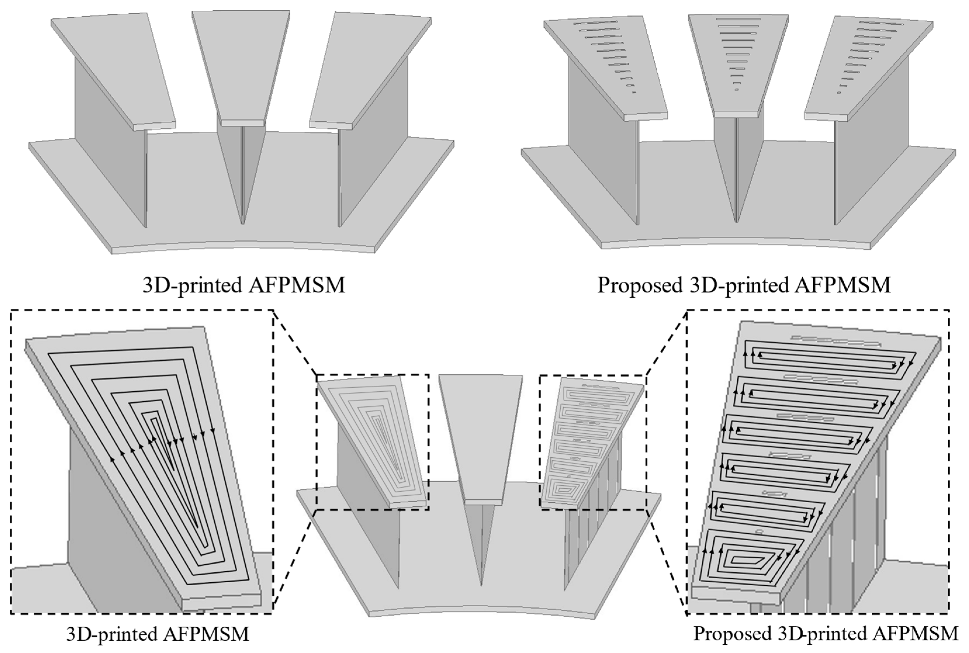
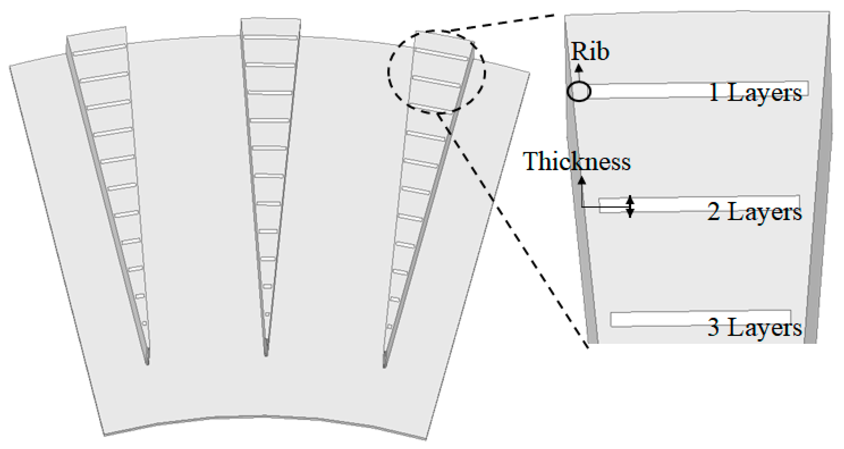
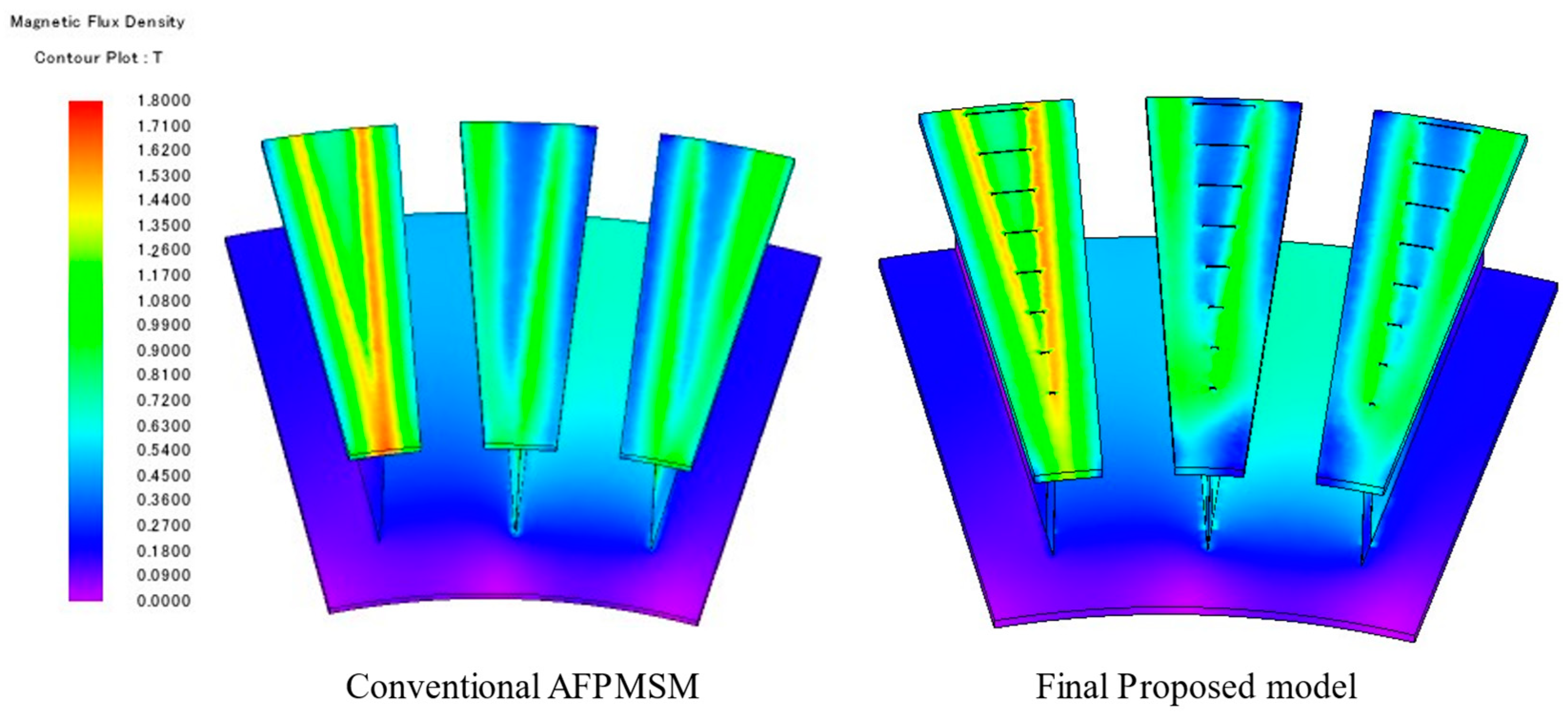
3.2. Proposed Stator Structure of AFPMSM

A conventional AFPMSM was proposed as a 3D-printed AFPMSM with shoe structures at the stator to increase performance compared to RFPMSM applied to a laundry machine [16]. To reduce the eddy current loss of the AFPMSM, a structure that adds a slit to the core structure is proposed. The conventional AFPMSM stator structure is presented, as shown in Figure 4 left. A novel 3D-printed AFPMSM stator structure is proposed, as shown in Figure 4 right. The air insulation layers, slits, are applied on the surface of the shoes to reduce eddy current loss. The shoe and slit of the structures, which lead to eddy current reduction, cannot be made by the conventional manufacturing process.
To be more specific, the shoe and slit structures change the magnetic flux at the air gap region compared to the conventional AFPMSM. Furthermore, the magnetic flux saturation levels are high because the area of the shoe is different compared to that of the conventional AFPMSM. From the eddy current loop analysis, the total length of the loop with the proposed model is shorter than that of the 3D-printed AFPMSM because of the slits. The effect of the slit in the proposed AFPMSM is the same as that of laminating sheets because the loop is divided by the slits. According to the principle of eddy current loss, it is estimated that the slits reduce eddy current loss. In addition, the eddy current can be reduced by increasing the electrical resistance from the increased shoe area affecting the current loop. The comprehensive performance analysis and optimal design processes are conducted and are presented in Section 4.

4. Parametric Analysis for an Optimal Design

In Section 3, it was estimated that the proposed model was theoretically effective in reducing the eddy current loss. The AFPMSM with the fixed specifications is presented in Table 1 to implement parametric analysis with design variables. The AFPMSM consists of 48 poles and 36 slots with 3 phases. The winding was wound as concentrated winding with 63 turns per phase. The winding is filled at 45% of the total area of the slot. Ferrite 7BE is selected as the permanent magnet. The dimension of the AFPMSM is also indicated in Table 1. The target performance of the proposed model was set to validate the estimated eddy current loss reduction based on these fixed specifications and dimensions. The details of the target performance of the AFPMSM, which are provided by the conventional AFPMSM without slits at the stator, are the same as the details of the characteristic performance. Especially, the targeted performance requires at least 1.85 Nm of torque at rated speed, 1200 RPM, and lower than 2.24 W of eddy current loss. Since the target rated power is 230 W, the minimum torque requirement is required over 1.85 Nm. The parametric analysis is conducted via finite element analysis (FEA) to find an optimal model with low eddy current loss while the performance is maintained.

4.1. Parameters of Stator Core with Slits

To reduce the eddy current loss of the proposed AFPMSM, the number and thickness of slits are selected as parameters. However, when the number of slits is significantly large at the stator teeth where flux linkage, which affects the performance of the motor, is formed, magnetic flux saturation, which will degrade the performance of the motor, will occur in the teeth because of the flow of magnetic flux from the permanent magnet. The thickness of the slits also produces a similar phenomenon. Furthermore, the width, called rib, also affects the performance of the motor. Therefore, this paper conducts a parametric performance analysis based on three variables—the number of slits, the thickness of slits, and the length of ribs. The parameters at the stator are presented in Figure 5.
Since the electrical resistance per area with below six layers does not increase significantly, the range of the layer is selected based on the mechanical stiffness and saturation level of the teeth, given that over ten layers do not affect eddy current loss. Considering that the saturation in the teeth and the thickness of the air insulation ranging less than 0.1 mm does not significantly affect the eddy current loss, the thickness of the slits is designed between 0.1 and 0.7 mm. Lastly, 0, 0.2, 0.4, and 0.6 mm of distance from the end of the stator are set as the length of ribs.

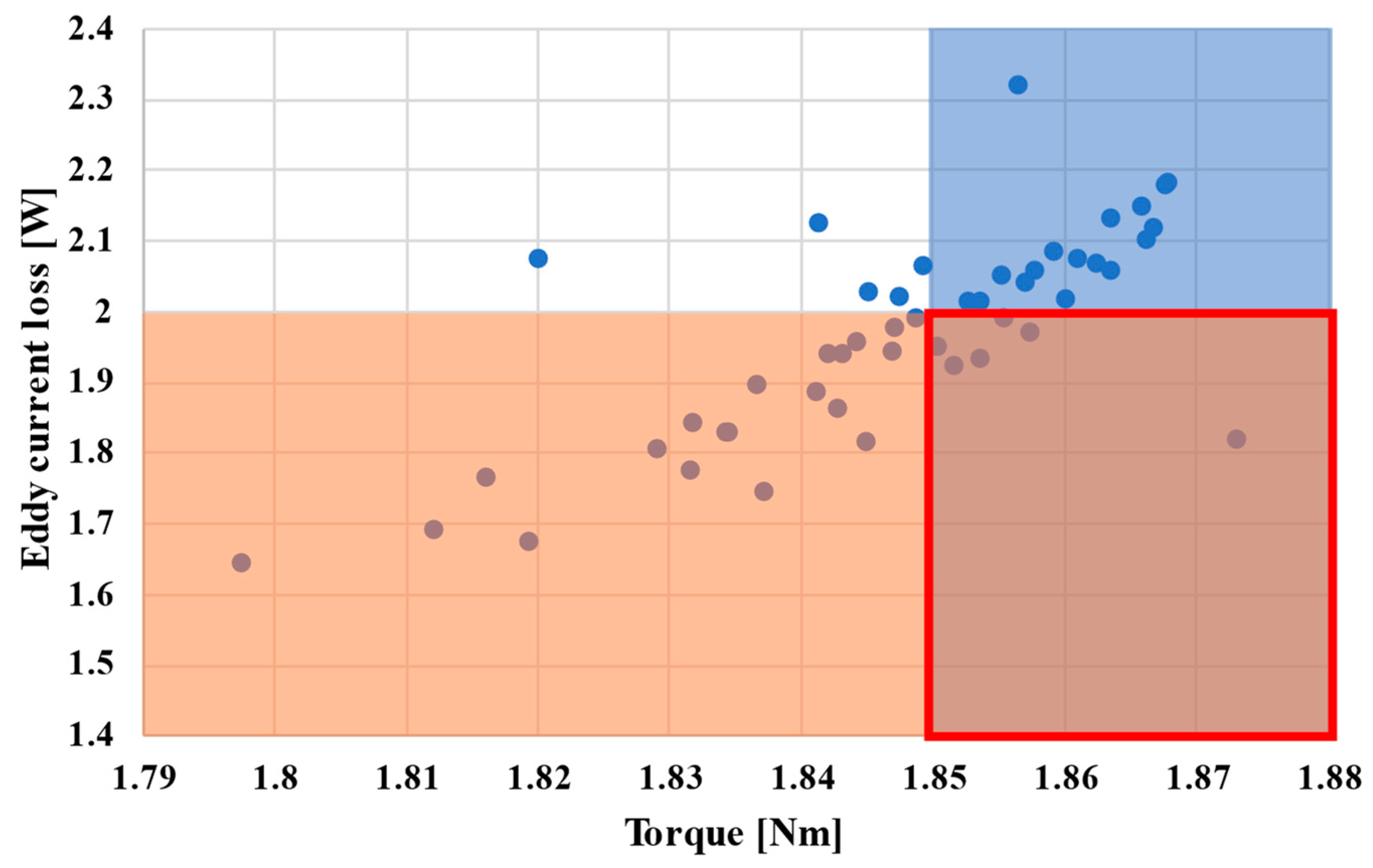
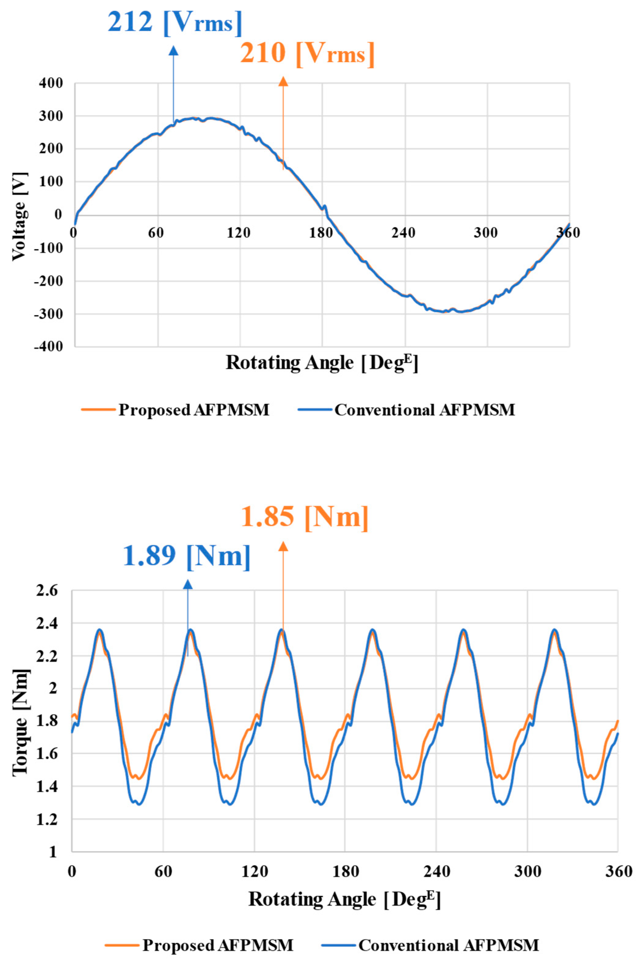
4.2. The Result of the Parametric Analysis

The eddy current loss was estimated by FEA analysis according to the parameters, the number and the thickness of slits, and the length of ribs in preliminary simulated results, as shown in Table 2. From the ranged parameters, it is indicated that the model with the biggest eddy current loss reduction, which is decreased by 28%, has ten layers and 0.7 mm of slit thickness without rib, and the model with the smallest eddy current loss reduction has six layers and 0.1 mm of slit thickness with 0.6 mm of rib. It is validated that eddy current loss was decreased with the proposed model—even the smallest eddy current loss reduction. The details of the parametric analysis will follow.
The FEA result presents that the eddy current loop comes out as expected when the slit area is selected as the longest thickness in the range (0.1–0.7 mm) compared to the other models, as shown in Figure 6. Since the proposed model leads to the electrical resistance of the stator teeth increasing, the eddy current loss reduces, as obtained through the FEA result. Based on eddy current loop analysis, the FEA result is presented as variables are changed, as shown in Figure 7. It states that there is a correlation between torque and eddy current loss. Since eddy current loss increases as torque increases in general, an optimization process is required for an optimal design.
The optimization process is conducted to find an optimal design of AFPMSM with the proposed model. The optimization results indicate that an area that satisfies the target torque is shown in blue, and another area that meets the eddy current loss is shown in red. Therefore, six models which meet the target performance with low eddy current loss are selected. Most candidates are concentrated in the ranges of 1.9–2.0 W of eddy current loss and 1.85–1.86 Nm of torque. However, a model with the most significant reduction in eddy current loss compared to the conventional is a model with eight layers, 0.1 mm slit thickness, and 0.6 mm rib thickness. The eddy current loss with the model was reduced by 18.75%, torque was decreased by 1.06%, and no-load BEMF was decreased by 0.94% compared to the conventional AFPMSM, as shown in Table 3 and Figure 8. A comparative magnetic flux density analysis is conducted to validate that the model with eight layers, 0.1 mm of slit thickness, and 0.6 mm of rib thickness is an optimal design. The magnetic flux density comparison between the conventional AFPMSM and the proposed model is presented in Figure 9.
It is validated that the magnetic flux has a maximum of 1.86 T in the conventional AFPMSM and 2.12 T in the proposed AFPMSM. The result from the magnetic flux density indicates that the magnitude of magnetic flux is decreased from saturation despite the eddy current loss reduction, as shown in Figure 9. Although there is a torque reduction from it, its torque at rated speed overrides the torque requirement. Therefore, the model is selected as an optimal model with significant eddy current loss reduction.
In summary, the slits in the proposed AFPMSM lead to lower eddy current loss, as shown in Table 4. Comparative eddy current loss and performance analysis between the conventional AFPMSM and the proposed AFPMSM validate that the proposed AFPMSM has low eddy current loss without a performance dip.

5. Conclusions

This paper proposed a novel AFPMSM with shoe and slit structures with parametric analysis for eddy current loss reduction. The simulated preliminary results indicate that the proposed idea with slits suppresses eddy current loss in the range 2.68–28%. Since it was validated that the three variables, the number of slits, the thickness of slits, and the length of the ribs, affect eddy current loss and torque by the preliminary result, a parametric analysis was conducted based on the three variables to find an optimal design. The parametric analysis result states that the model with eight layers, 0.1 mm of slit thickness, and 0.6 mm of rib length leads to the lowest eddy current loss while the performance is maintained compared to the conventional 3D-printed AFPMSM without slits. The proposed model provides a reduction in eddy current loss of 18.75%. With the development of 3D printing technology, new shapes of motors are increasing.

Author Contributions

Conceptualization, W.-H.K.; methodology, H.-J.P.; software, H.-J.P.; validation, H.-J.P.; formal analysis, H.-J.P.; investigation, H.-J.P.; resources, H.-J.P.; data curation, H.-J.P.; writing—original draft preparation, H.-J.P.; writing—review and editing, H.-J.P. and K.L.; visualization, J.-Y.M. and M.-K.H.; supervision, W.-H.K. All authors have read and agreed to the published version of the manuscript.

Funding

This work was supported by the National Research Foundation of Korea (NRF) grant funded by the Korea government (MSIT) (No. 2020R1A2C1013724) and in part by the Gachon University research fund of 2019 (No. 2019-0706).

Institutional Review Board Statement

Not applicable.

Informed Consent Statement

Not applicable.

Data Availability Statement

Not applicable.

Conflicts of Interest

Not applicable.

References

  1. Bertola, L.; Cox, T.; Wheeler, P.; Garvey, S.; Morvan, H. Thermal design of linear induction and synchronous motors for electromagnetic launch of civil aircraft. IEEE Trans. Plasma Sci. 2017, 45, 1146–1153. [Google Scholar] [CrossRef]
  2. Qiwei, X.; Cui, S.; Zhang, Q.; Song, L.; Li, X. Research on a new accurate thrust control strategy for linear induction motor. IEEE Trans. Plasma Sci. 2015, 43, 1321–1325. [Google Scholar] [CrossRef]
  3. Braun, N.J. Some aspects of the application of induction motors to aircraft. Electr. Eng. 1944, 63, 769–772. [Google Scholar] [CrossRef]
  4. Larabee, J.; Pellegrino, B.; Flick, B. Induction motor starting methods and issues. In Proceedings of the Record of Conference Papers Industry Applications Society 52nd Annual Petroleum and Chemical Industry Conference, Denver, CO, USA, 12–14 September 2005; pp. 217–222. [Google Scholar]
  5. Simba, K.G.; Quilumba, F.L.; Granda, N.V. Parameter estimation of a three-phase induction motor from direct starting stator transient measurements. In Proceedings of the IEEE ANDESCON 2020, Quito, Ecuador, 13-16 October 2020; pp. 1–5. [Google Scholar]
  6. Guven, M.; Lee, K.; Dong, Y.; Lee, W. Shunt-connected solar microinverter for induction motor soft-starting and active and reactive power compensation. In Proceedings of the 2022 IEEE Energy Conversion Congress and Exposition (ECCE), Detroit, MI, USA, 9–13 October 2022; pp. 1–6. [Google Scholar]
  7. Morimoto, S.; Ooi, S.; Inoue, Y.; Sanada, M. Experimental evaluation of a rare-earth-free pmasynrm with ferrite magnets for automotive applications. IEEE Trans. Ind. Electron. 2014, 61, 5749–5756. [Google Scholar] [CrossRef]
  8. Bostanci, E.; Moallem, M.; Parsapour, A.; Fahimi, B. Opportunities and challenges of switched reluctance motor drives for electric propulsion: A comparative study. IEEE Trans. Transp. Electrif. 2017, 3, 58–75. [Google Scholar] [CrossRef]
  9. Kong, H.; Lee, K.; Pyo, H.; Jeong, M.; Kim, W. Robust design process to restrain irreversible demagnetization of interior permanent magnet synchronous motor applied in railway vehicles using dysprosium-free permanent magnet. J. Electr. Eng. Technol. 2021, 16, 617–623. [Google Scholar] [CrossRef]
  10. Zhang, Z.; Profumo, F.; Tenconi, A. Axial Flux Versus Radial Flux PM Motors; SPEEDAM: Capri, Italy, 1996; pp. A4-19–A4-25. [Google Scholar]
  11. Cavagnino, A.; Lazzari, M.; Profumo, F.; Tenconi, A. A comparison between the axial flux and the radial flux structures for PM synchronous motors. IEEE Trans. Ind. Appl. 2002, 38, 1517–1524. [Google Scholar] [CrossRef]
  12. Aydin, M.; Huang, S.; Lipo, T.A. Torque quality and comparison of internal and external rotor axial flux surface-magnet disc machines. IEEE Trans. Ind. Electron. 2006, 53, 822–830. [Google Scholar] [CrossRef]
  13. Bi, Y.; Pei, Y.; Chai, F. A novel axial flux interior permanent magnet motor with high torque density. In Proceedings of the 2019 22nd International Conference on Electrical Machines and Systems (ICEMS), Harbin, China, 11–14 August 2019; pp. 1–5. [Google Scholar]
  14. Aydin, M.; Gulec, M. A new coreless axial flux interior permanent magnet synchronous motor with sinusoidal rotor segments. IEEE Trans. Magn. 2016, 52, 1–4. [Google Scholar] [CrossRef]
  15. Su, J.; Wang, Y.P.; Tsai, M.; Tsai, K.; Lai, D. Flip chip assembly on coreless substrate challenge with die bond solution. In Proceedings of the 2019 22nd European Microelectronics and Packaging Conference & Exhibition (EMPC), Pisa, Italy, 16–19 September 2019; pp. 1–5. [Google Scholar]
  16. Pyo, H.J.; Jeong, J.W.; Yu, J.; Nam, D.W.; Yang, S.H.; Kim, W.H. Eddy current loss reduction in 3d-printed axial flux motor using 3d-printed smc core. In Proceedings of the 2020 IEEE Energy Conversion Congress and Exposition (ECCE), Detroit, MI, USA, 11–15 October 2020; pp. 1121–1125. [Google Scholar]
  17. Li, X.; Roberts, M.; O’Keeffe, S.; Sercombe, T. Selective laser melting of Zr-based bulk metallic glasses: Processing, microstructure and mechanical properties. Mater. Des. 2016, 112, 217–226. [Google Scholar] [CrossRef]
  18. Gu, D.; Meiners, W.; Wissenbach, K.; Poprawe, R. Laser additive manufacturing of metallic components: Materials, processes and mechanisms. Int. Mater 2012, 57, 133–164. [Google Scholar] [CrossRef]
  19. Hong, H.S.; Liu, H.C.; Cho, S.Y.; Lee, J.; Jin, C.S. Design of high-end synchronous reluctance motor using 3-d printing technology. IEEE Trans. Magn. 2017, 53, 1–5. [Google Scholar] [CrossRef]
  20. Wu, S.T.; Huang, P.W.; Chang, T.W.; Jiang, I.H.; Tsai, M.C. Application of magnetic metal 3-d printing on the integration of axial-flow impeller fan motor design. IEEE Trans. Magn. 2021, 57, 1–5. [Google Scholar] [CrossRef]
  21. Shin, D.; Jeong, M.; Lee, K.; Lee, K.; Kim, W. A study on the improvement of torque density of an axial slot-less flux permanent magnet synchronous motor for collaborative robot. Energies 2022, 15, 3464. [Google Scholar] [CrossRef]
  22. Kim, C.-W.; Jang, G.-H.; Kim, J.-M.; Ahn, J.-H.; Baek, C.-H.; Choi, J.-Y. Comparison of Axial Flux Permanent Magnet Synchronous Machines with Electrical Steel Core and Soft Magnetic Composites Core. IEEE Trans. Magn. 2017, 53, 1–4. [Google Scholar] [CrossRef]
  23. Wang, Y.; Lu, J.; Liu, C.; Lei, G.; Guo, Y.; Zhu, J. Development of a High-Performance Axial Flux PM Machine With SMC Cores for Electric Vehicle Application. IEEE Trans. Magn. 2019, 55, 1–4. [Google Scholar] [CrossRef]
  24. Scheerlinck, B.; De Gersem, H.; Sergeant, P. 3-D Eddy current and fringing-flux distribution in an axial-flux permanent-magnet synchronous machine with stator in laminated iron or SMC. IEEE Trans. Magn. 2015, 51, 1–4. [Google Scholar] [CrossRef]
  25. Wang, X.; Zhou, S.; Wu, L.; Zhao, M.; Hu, C. Iron loss and thermal analysis of high speed pm motor using soft magnetic composite material. In Proceedings of the 2019 22nd International Conference on Electrical Machines and Systems (ICEMS), Harbin, China, 11–14 August 2019; pp. 1–4. [Google Scholar]
Figure 1. Example of 3D printing structure production [16].
Energies 16 01318 g001
Figure 2. Comparison B-H Curve and Coreloss data of existing SMC and 3D-printed SMC [16].
Energies 16 01318 g002
Figure 3. Example of eddy current loss path [16] (a) Basic eddy current loop path; (b) eddy current loop path through lamination.
Energies 16 01318 g003
Figure 4. Design comparison between the conventional 3D-printed AFPMSM and proposed 3D-printed AFPMSM [16].
Energies 16 01318 g004
Figure 5. Parameters for optimization of the proposed model [16].
Energies 16 01318 g005
Figure 6. Upper image and under image shows the comparison of eddy current loss path [16].
Energies 16 01318 g006
Figure 7. Satisfied eddy current loss and torque graph.
Energies 16 01318 g007
Figure 8. Performance comparison between the final proposed model and the conventional AFPMSM model.
Energies 16 01318 g008
Figure 9. Magnetic flux density comparison between the conventional AFPMSM and the proposed AFPMSM.
Energies 16 01318 g009
Table 1. Specification of conventional AFPMSM.
ParameterValueUnit
Characteristic
Performance
Pole/Slot48/36-
Speed1200RPM
Torque1.85Nm
Current2.02Arms
Power230W
Eddy current loss2.24W
WindingMaterialAluminum-
Diameter1.3mm
Turns63-
Y-Connection--
Fill Factor45%
Permanent MagnetMaterialFerrite 7BE-
CoreMaterial3D-printed SMC-
DimensionOuter Diameter288mm
Inner Diameter178.3mm
Stator Back-Yoke1.2mm
Teeth Length21.5mm
Air Gap1mm
Shoe Thick1.2mm
Magnet Thick3.1mm
Rotor Back-Yoke2mm
Table 2. Preliminary simulated results.
Value6 Layers
Thick 0.1 mm Rib 0.6 mm
10 Layers
Thick 0.7 mm Rib 0 mm
Unit
Rotor Back-Yoke0.0330.032W
Total Shoe0.880.733W
Stator Back-Yoke0.2030.186W
Total Teeth1.0640.689W
Total Eddy Current Loss2.181.64W
Table 3. Models that satisfy the target performance.
ModelsEddy Current Loss [W]Torque [Nm]Loss Reduction [%]
8 Layers_Thick0.1mm_Rib0.6mm 1.821.8718.75
6 Layers_Thick0.3mm_Rib0mm1.931.8513.84
6 Layers_Thick0.3mm_Rib0.2mm1.971.8612.05
8 Layers_Thick0.3mm_Rib0.2mm1.991.8611.16
10 Layers_Thick0.3mm_Rib0.4mm1.921.8514.29
6 Layers_Thick0.5mm_Rib0.2mm1.951.8512.95
Table 4. Performance comparison summary.
Loss and PerformanceConventionalProposed
Rotor Back Yoke [W] 0.0370.034
Total Stator [W]2.211.76
Total Eddy Current Loss [W]2.241.82
Hysteresis Loss [W]33.3236.3
Torque [Nm]1.891.87
Disclaimer/Publisher’s Note: The statements, opinions and data contained in all publications are solely those of the individual author(s) and contributor(s) and not of MDPI and/or the editor(s). MDPI and/or the editor(s) disclaim responsibility for any injury to people or property resulting from any ideas, methods, instructions or products referred to in the content.

