Abstract
In recent years, the open microchannel has drawn increasing interest, but severe local dryout limited the heat transfer capability of flow boiling. It was anticipated that nanostructures with exceptional capillary wicking abilities would overcome this problem. In this study, blade-like CuO nanostructures were created in the copper open microchannels to experimentally investigate water flow boiling. Experiments were carried out in nanostructured open microchannels (NMCs), and smooth-surface open microchannels (SMCs), as a comparison, were examined under identical operating conditions. Four main flow patterns, including bubbly flow, slug flow, and two kinds of stratified flow, dominated successively in NMCs and SMCs. Although the flow patterns were similar in NMCs and SMCs, the heat transfer coefficient (HTC) of flow boiling was greatly enhanced by nanostructures under conditions of medium and high heat flux, while the nanostructures’ influence on HTC was unnoticeable at low heat flux. At medium and high heat fluxes, the dependence of HTC on heat flux and flow rate indicated the joint contribution of nucleate boiling mechanism and convective evaporation mechanism to heat transfer. The enhanced effect of nanostructures on nucleate boiling and convective evaporation became more prominent as heat flux increased, leading to a higher HTC in NMCs than in SMCs at higher heat flux conditions.
1. Introduction
Electronic equipment and energy storage devices with increasing power and heat flux face severe heat dissipation problems [1,2]. Microchannel flow boiling has a very large heat transfer capability, making it one of the most promising strategies for enhancing heat dissipation and improving thermal management [3,4,5]. The open microchannel is a type of microchannel heat sink with a unique flow passage configuration [6]. It forms an open gap over the microchannels, offering additional space for the expansion of bubbles and vapor clots downstream, significantly suppressing two-phase flow instability and reducing the pressure drop. Hence, the open microchannel heat sink has attracted great attention in recent years.
An open microchannel heat sink with a tapered manifold was designed by Kandlikar et al. [7], which mitigated reverse flow and reduced the pressure fluctuation. The highest HTC reached 193 kW/(m2K), and the significant improvement in heat dissipation capability was attributed to the open space over the microchannels. Kalani et al. [6] analyzed the mechanism of bubble dynamic behaviors (including bubble nucleation, growth, and departure) during flow boiling in open microchannels. They claimed that the bubble behaviors within the channel region had no negative influence on the overall stability of two-phase flow due to the extensive interlinked vapor space distributed over the channels. Balasubramanian et al. [8] investigated the spatial orientation impacts on heat transfer performances of flow boiling in an open microchannel heat sink. It was confirmed that the performance of open microchannels was independent of orientation. Qiu et al. [9] experimentally studied and visualized flow boiling in an open microchannel heat sink. Because of the open space, the stratified slug/annular flow was crucial for improving heat dissipation. Zhao et al. [10] investigated flow boiling in large-aspect-ratio open microchannels. It effectively separated liquid and vapor during two-phase flow, accelerating evaporation in the liquid film. Fattahi et al. [11] evaluated flow boiling in open microchannels with a variety of geometric-shaped fins. The open microchannel with plane–convex model was the most efficient alternative and provided the best performance. Bhandari et al. [12] studied how heat transfer and flow parameters were influenced in open microchannels. It was obvious that open microchannels had less pressure drop than closed channels. In general, the flowing liquid and vapor in the open microchannels were relatively undisturbed, resulting in an HTC improvement. However, the increased flow stability and reduced pressure drop in open microchannels are always accompanied by local dryout, resulting in a limited HTC improvement.
Numerous efforts have been devoted to further enhance the flow boiling heat dissipation performance of open microchannels. Modifying channel surface with micro-/nanostructures [13,14] is a crucial method for improving heat transfer. Lin et al. [15] examined the influence of microscale pores on the heat dissipation of flow boiling in a microchannel. Benefiting from the superhydrophobic wettability and enormous number of possible nucleation sites of the microscale porous structures, the average two-phase HTC was increased by up to 74.84% because of earlier boiling inception and enhanced boiling intensity. Markal et al. [16] investigated flow boiling in a microgap with a diminishing number of micro-pin fins. The flow boiling thermal performance was greatly improved compared to the conventional uniformly distributed micro-pin fins, along with the reduced surface temperature fluctuations and flow instabilities. However, enhancing the heat transfer of microchannel flow boiling by modifying channel surface using microstructures generally induces an additional pressure drop penalty, but using nanostructures does not. Specifically, nanostructures can significantly delay local dryout by changing the surface wettability [17,18,19]. Morshed et al. [20] explored flow boiling heat dissipation performance in a single side-heated Cu microchannel with a thin nanocomposite layer covering the bottom surface. The alteration in the surface morphology caused by the nanocomposite coating was attributed for the improvement in boiling performance. Wang et al. [21] developed a silicon-based microchannel heat sink with nanowire coatings. Their findings showed that, in comparison to plain-wall microchannels, nanowire coatings could improve the heat dissipation capabilities of microchannels while lowering the two-phase pressure drop. Sharma et al. [22] analyzed the flow boiling performance in conventional closed microchannels, with a smooth and nanostructured surface. The results showed that the capillary wicking offered by nanostructures could greatly reduce the temperature oscillations and improve the HTC under high heat-flux conditions. Ghosh et al. [23] fabricated nanostructures in copper microchannels via chemical oxidation. Compared to smooth-surface microchannels, nanostructured microchannels displayed superior heat transfer performance. Alam et al. [24] carried out flow boiling experiments in microchannels with superhydrophilic nanowires. They found that the nanowires could improve liquid rewetting and increase the HTC by about 400% while decreasing the pressure drop by about 70%. Lim et al. [25] created a nanostructured surface in mini-/micro-channel ducts to evaluate flow boiling performance. The increased wicking effects facilitated liquid rewetting and suppressed local dryout, considerably enhancing the boiling heat transfer. Di Sia et al. [26] created nanocomposite coatings in a mini-channel to raise the heat transfer of flow boiling. The nano-coatings encouraged rapid liquid penetration, facilitated bubble detachment, and inhibited local dryout during the boiling process, resulting in the highest boiling HTC.
In the authors’ previous work [27,28], it was found that the open microchannel heat sink (with a smooth surface) could suppress flow instability, lower pressure drop, and improve HTC in comparison to the conventional closed microchannels. However, local dryout occurred at high heat fluxes, causing an HTC reduction with increasing heat flux. The present work is actually a follow-up study of previous ones, with the objective of eliminating severe local dryout and further improving the heat dissipation capability in an open microchannel heat sink. From a review of the relevant literature, it is obvious that nanostructures could offer the additional capillary force that is advantageous for pumping the liquid back onto the heat exchange surface, effectively preventing local dryout. Could nanostructures be utilized to change the surface wettability of open microchannels to prevent local dryout and additionally improve the HTC of flow boiling? In this study, blade-like nanostructures were fabricated on the open microchannel surface to examine the flow boiling performance. The flow patterns were visualized and the HTC was measured. The impact of blade-like nanostructures on water flow boiling was analyzed.
2. Experimental Investigation
2.1. Experimental Setup
Figure 1 shows the experimental system schematic. Before experiments, DI water was fully degassed by applying low pressure many times. A micro-gear pump was used to circulate the degassed DI water. A flowmeter was employed to monitor the flow rate. A constant-temperature bath preheated the liquid to the desired inlet temperature. Working fluid was heated and vigorously vaporized in the test section. Flow boiling was visualized via a high-speed CCD camera. The two-phase fluid was drained from the open microchannels and cooled in a condenser before it returned to the liquid tank. Pressure transmitters and K-type thermocouples measured the test section inlet and outlet pressures and fluid temperatures.
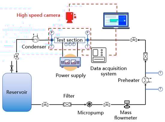
Figure 1.
Experimental system schematic.
2.2. Test Section
Figure 2 schematically depicts the test section. It was made up of two aluminum plates, a copper heating block, a polyphenylene ether (PPE) cover plate, a silica gel gasket, and a Teflon insulating layer. The copper block was encased in Teflon insulation for thermal insulation and then placed between two aluminum plates. The copper block with microchannels was covered by a transparent PPE plate to visualize the flow. A silicone gasket was placed in the middle of the cover plate and the copper block for sealing. Three groups of small holes were drilled 1.3 mm below the microchannel and thermocouples were installed to gauge the temperature distribution of microchannels. To diminish heat loss to the ambient, the insulation blanket was draped around the test section. The micro-milling cutter was used to machine 25 parallel microchannels on the copper block’s top surface. The size of the microchannel was 0.2 mm wide, 0.2 mm high, and 20 mm long. As shown in Figure 3, an expanding slit was set between the cover plate and the microchannel to provide an open space with gradual expansion from the inlet to the outlet. CuO nanostructures were fabricated on the entire microchannel surface to improve the surface wettability.
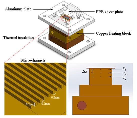
Figure 2.
Test section schematic.
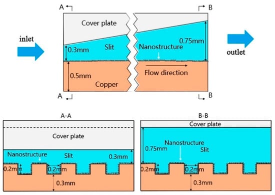
Figure 3.
Schematic diagram of the open microchannel flow passage.
2.3. Experimental Conditions and Surface Structure
The flow boiling experiment was carried out under atmospheric pressure. The mass flow rates ranged from 177 to 438 mL/min, while the liquid inlet temperature was kept at Tin = 90 °C. According to the method described by Huang et al. [29], the surface of the microchannels was treated with chemical etching to create a coating of blade-like nanostructures. At first, the copper microchannels were submerged into KOH (2.5 mol/L) and K2S2O8 (0.065 mol/L) mixture solution. The solution was warmed for 30 min in a water bath at 70 °C. After that, the copper microchannels were washed twice or thrice with DI water and dried in a 105 °C oven for 30 min. Finally, a layer of blade-like nanostructures was generated on the channel surface. Figure 4 shows an image of the nanostructures produced by scanning electron microscopy. A video contact angle measurement instrument (Model: SDC-350) was utilized to evaluate the wetting characteristics of DI water on the smooth surface and the nanostructured surface, respectively. It was obtained that the DI water contact angle on the smooth surface was 101°, but it was nearly 0° on the nanostructured surface, showing super-hydrophilicity.
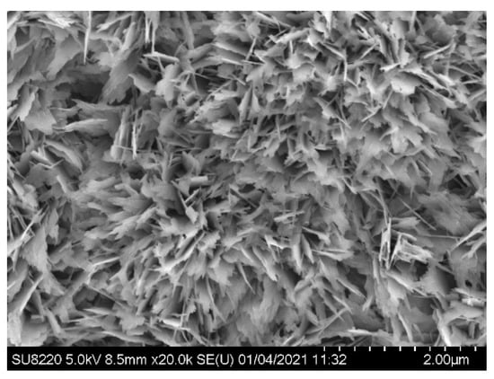
Figure 4.
SEM image of the blade-like CuO nanostructures.
2.4. Data Reduction and Uncertainty Analysis
The data reduction followed the method described by Kandlikar et al. [7]. Fourier’s heat conduction law was used to calculate the heat flux q:
where kCu is copper thermal conductivity and dT/dx is temperature gradient of copper in height direction, which was computed by:
where T1, T2, and T3 are temperatures measured by thermocouples aligned vertically from top to bottom. Δx = 4 mm is the interval between two adjacent measuring points.
Fourier’s law of heat conduction was used to calculate the microchannel’s wall temperature:
where x1 = 1.3 mm is the interval between the top thermocouple and the channel bottom wall.
Newton’s cooling formula was used to compute HTC:
The measured parameter uncertainties were approximated according to the accuracies of measuring devices, while the computed parameter uncertainties were estimated using Moffat’s method [30]. Table 1 lists the uncertainty analysis results.

Table 1.
Uncertainties of parameters.
3. Results and Discussion
3.1. Flow Pattern Characteristics
Four main flow patterns successively dominated the flow boiling in NMC and SMC: bubbly flow, slug flow, and two kinds of stratified flow. Figure 5 shows typical flow patterns in NMC. As displayed in Figure 5a, the two-phase flow was dominated by the isolated bubbles after the boiling inception. Bubbles nucleated and grew at the nucleation site and then departed from the surface of the channel or the top of the rib. With increasing heat flux, more nucleation sites were activated and the bubble nucleation rate increased. Moreover, the bubble’s growth accelerated and began to be confined by channels or the open slit. The confined bubbles expanded rapidly and merged with the adjacent ones in the open space to form the vapor slug, indicating the inception of the slug flow, as depicted in Figure 5b. Vapor slugs developed into vapor clots with the continuous heat flux increase, because of the sustained bubble expansion and coalescence, forming Type-I stratified flow, as shown in Figure 5c. Vapor mainly flowed in the open space over the channels during Type-I stratified flow, so the top surface of the ribs was covered by vapor blankets, while liquid mainly flowed in the channels and bubbles continued to nucleate and grow in them. With a further heat flux increase, the vapor clots connected with the bubbles in the channel to occupy the whole cross section of the flow passage, while liquid flowed as a thin layer adhering to the cover plate, forming Type-II stratified flow, as shown in Figure 5d. It can be seen that the two kinds of stratified flow alternately appeared and local dryout may happen on the wall surface during Type-II stratified flow.
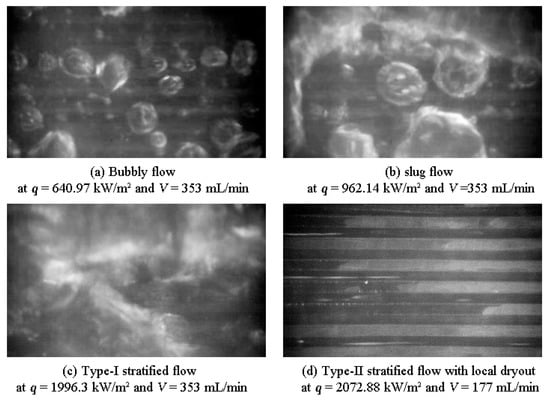
Figure 5.
Flow patterns in NMC.
Since the boiling flow patterns greatly depend on the heat flux q and the flow rate V, Figure 6 shows the flow operational map in NMC as a function of heat flux and flow rate. It was noted that the bubbly flow and the slug flow both appeared under low and medium heat-flux conditions, while the stratified flow happened under high heat fluxes for various flow rates. In addition, with increasing flow rate, the flow pattern transition boundary moved towards the higher heat flux, induced by the decreased bubble nucleation-site density and the reduced bubble growth rate at higher liquid flow rate. It needs to be stressed that Type-II stratified flow was only observed under small flow rate conditions in this study, which did not mean that it would not occur at a large flow rate. The flow pattern transition boundary moved to higher heat flux with the increment in flow rate, which indicated that Type-II stratified flow would also occur under large flow rate conditions if the heat flux became continually larger.
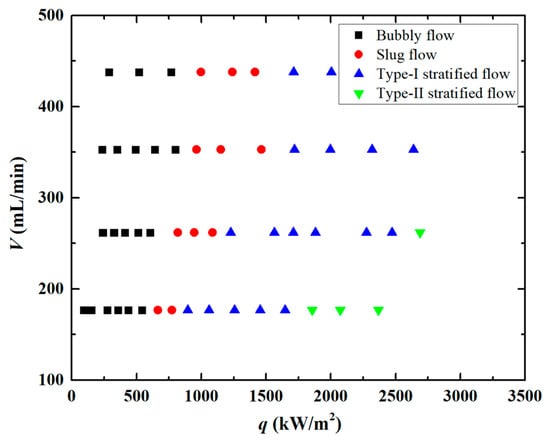
Figure 6.
Flow operational map during flow boiling in NMC.
3.2. Boiling Curves
Figure 7 depicts the boiling curves of NMC and SMC at four different flow rates. For the boiling curves of NMC, it was noted that the wall superheat decreased with a flow rate increase for a given heat flux. It is well known that the nucleate boiling mechanism and the convective evaporation mechanism coexist during flow boiling in microchannels, so the heat transfer can be considered as the net effect of both heat dissipation modes. The large flow rate increased the bubble departure frequency, resulting in the improved nucleate boiling heat transfer. Moreover, convective evaporation is related to heat conduction and heat convection through a thin liquid film with evaporation at the liquid–vapor interface (L–V interface). A flow-rate increase strengthened the interfacial disturbance, which induced the secondary recirculating flows and enhanced the turbulence strength in the liquid film, hence, raising heat transfer effectiveness through the liquid film (i.e., decreasing the thermal resistance of the liquid film) and improving evaporation. The improved performance of both heat dissipation modes with the increased flow rate reduced the wall temperature under conditions of constant heat flux. However, for SMC, the increase in flow rate did not always reduce the wall superheat. Figure 7b reveals that in SMC, the wall superheat for V = 438 mL/min was slightly higher than that for V = 353 mL/min at the same heat fluxes. Due to the condensation of the nucleate bubbles and the instability of the L–V interface contacting with the subcooled liquid, the nucleation-site density in the SMC may significantly decrease as the flow rate increases, reducing the heat dissipation capacity and increasing the wall superheat for a given heat flux.
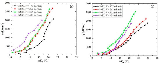
Figure 7.
Boiling curves for (a) NMC and (b) SMC.
Figure 7 reveals that the boiling curves of NMC moved to the left compared to those of SMC, implying that the open microchannels with nanostructures had superior heat transfer performance. It is well known that nanostructures could greatly increase the nucleation-site density and decrease the boiling inception heat flux, resulting in more vigorous nucleation boiling and reduced wall superheat in NMC than in SMC under the same operating conditions. In addition, the reduced bubble departure diameter and the increased bubble departure frequency caused by the nanostructures also contribute to enhancing the heat transfer of nucleation boiling. When the flow pattern transformed from bubbly/slug flow to a stratified one with a heat-flux increase, the enhanced effect of nanostructures on the heat transfer became more prominent. During bubbly/slug flow, the dominant heat transfer mechanism was nucleate boiling; the enhanced effect of nanostructures on the heat transfer functioned only through enhanced nucleation boiling. However, with increasing heat flux, the flow pattern changed to stratified flow, during which the heat transfer was together determined by a nucleation boiling mechanism and convective evaporation mechanism. The increased heat flux triggered more nucleation sites. In addition, the nanostructures enlarged the L–V interface and improved the liquid rewetting capability. This meant that during stratified flow, the enhanced effect of nanostructures on the heat transfer worked not only by enhancing the nucleation boiling, but also by enhancing convective evaporation. Moreover, nanostructures with a strong capillary suction capability and rapid liquid rewetting could inhibit local dryout and improve CHF, as reported in numerous publications. As displayed in Figure 7, the SMC wall superheat increased to 30 °C and the heat transfer began to degrade as the heat flux reached 1875.37 kW/m2 at 177 mL/min flow rate, whereas the NMC wall superheat was only 22.7 °C even at 2072.87 kW/m2 heat flux and the heat transfer did not deteriorate at this time under the same flow rate condition.
3.3. Heat Transfer Coefficient
Figure 8 displays HTC versus heat flux for NMC and SMC to demonstrate the enhanced effect of nanostructures on heat transfer. The HTC of two kinds of microchannels rose with increasing heat flux under all flow rates, demonstrating the significance of the nucleate boiling mechanism within the studied heat-flux range. It could be noted that the flow rates hardly affect HTC under low heat fluxes (q < 600 kW/m2), which was determined by the dominated bubbly flow. The dependence of HTC on flow rate became more apparent with increasing heat flux. At medium and high heat fluxes, the slug or stratified flow dominated, during which HTC was jointly affected by nucleation boiling and convective evaporation, leading to the increased HTC with increasing liquid flow rate.
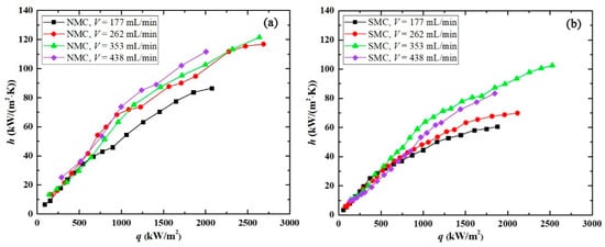
Figure 8.
HTC for (a) NMC and (b) SMC.
The comparison of HTC in NMC and SMC at four different flow rates can also be noted in Figure 8. HTC of the nanostructured open microchannels was always greater than that of the smooth-surface open microchannels. Moreover, the disparity between them grew as the heat flux rose. The nanoscale cavities provided by the nanostructures served as the potential nucleation sites and required a substantially larger superheat or heat flux to be activated according to Hsu’s classic nucleation theory [31]. Therefore, although there were more potential nucleation sites for bubble generation in NMC, they were not fully activated during the early boiling stage due to the comparatively low heat flux. The potential nucleation sites began to be fully activated with increasing heat flux, leading to the escalating enhancement effect of nanostructures on the nucleation boiling. In medium and high heat-flux ranges, the stratified flow dominated two-phase flow. For Type-I stratified flow, nucleation boiling and convective evaporation together controlled the heat transfer. In NMC, nucleation boiling in the liquid layer was enhanced because of the increased nucleation-site density and bubble departure frequency; meanwhile, the convective evaporation at the L–V interface was improved due to the enlarged heat exchange surface, resulting in a larger HTC in NMC than SMC. Although the flow pattern would change to Type-II stratified flow in both NMC and SMC as the heat flux rose under conditions of small flow rate, the characteristics of heat transfer were distinct. The greatly improved surface hydrophilicity in NMC by the blade-like nanostructures contributed to the liquid rewetting and the suppression of the local dryout under high heat fluxes, causing a higher HTC in NMC than in SMC. It can be found from Figure 8 that the HTC in NMC was about 1.5-times greater than that in SMC at q = 2115.04 kW/m2 and V = 262 mL/min. Overall, the flow boiling heat dissipation capability of the open microchannels was greatly improved by nanostructures under medium and high heat fluxes.
4. Conclusions
Water flow boiling was experimentally investigated in open microchannels with blade-like nanostructures. The following findings were obtained:
- As the heat flux increased, the bubbly flow, slug flow, and stratified flow were seen successively in NMC and SMC. The flow pattern transition boundary shifted to a larger heat flux with increasing flow rate, which could be attributed to the decreased bubble nucleation-site density and the reduced bubble growth rate at a larger liquid flow rate.
- The enhanced effect of nanostructures on the NMC’s flow boiling heat dissipation mainly functioned at higher heat flux conditions. The HTC of NMC was slightly higher than that of SMC under low heat fluxes (q < 600 kW/m2) and was unaffected by liquid flow rate. However, under high heat fluxes, the HTC of NMC was about 1.5-times larger than that of SMC, and it increased with an increment in liquid flow rate.
- The heat transfer was controlled by nucleation boiling in bubbly flow and the initial stage of slug flow. During these flow patterns, the nanostructures’ effect on HTC was unnoticeable because of the relatively low heat flux, since the nanoscale cavities provided by the nanostructures required a relatively larger heat flux/wall superheat to be activated as the bubble nucleation sites.
- The nucleation boiling mechanism and convective evaporation mechanism together determined the heat transfer during the later stage of slug flow and stratified flow. The blade-like nanostructures enhanced nucleation boiling via increasing bubble nucleation-site density and bubble departure frequency, improved convective evaporation via enlarging the L–V interface, and suppressing local dryout, jointly resulting in the better heat dissipation performance of NMC under higher heat fluxes.
Using blade-like nanostructures to optimize the flow boiling heat transfer performance of an open microchannel heat sink is promising in real engineering applications because the cost of producing the nanostructures is relatively low. In this study, however, neither the fouling nor the deterioration of nanostructures was investigated. Further research on the aforementioned problems and a comparison study with other nanostructures are planned.
Author Contributions
Conceptualization, L.Y.; validation, Z.Y., Y.X. and K.Z.; investigation, L.Y., Y.X. and C.D.; data curation, Y.X. and Z.Y.; writing—original draft preparation, L.Y. and Y.X.; writing—review and editing, L.Y.; visualization, Y.X. and Z.Y.; supervision, L.Y. All authors have read and agreed to the published version of the manuscript.
Funding
This research was funded by the Fundamental Research Funds for the Central Universities (2022JBZY037) and the National Natural Science Foundation of China (No. 52276047).
Institutional Review Board Statement
Not applicable.
Informed Consent Statement
Not applicable.
Conflicts of Interest
The authors declare no conflict of interest.
References
- Liu, R.; Zhang, L.; Zhang, X. Applications of Spray Cooling Technology in Aerospace Field; IOP Conference Series: Materials Science and Engineering, 2019; IOP Publishing: Bristol, UK, 2019; p. 12020. [Google Scholar]
- Li, B.; Huang, K.; Yan, Y.; Li, Y.; Twaha, S.; Zhu, J. Heat transfer enhancement of a modularised thermoelectric power generator for passenger vehicles. Appl. Energy 2017, 205, 868–879. [Google Scholar] [CrossRef]
- Piasecka, M.; Strąk, K. Boiling Heat Transfer during Flow in Vertical Mini-Channels with a Modified Heated Surface. Energies 2022, 15, 7050. [Google Scholar] [CrossRef]
- Moreira, D.; Nascimento, V.; Ribatski, G.; Kandlikar, S. Combining liquid inertia and evaporation momentum forces to achieve flow boiling inversion and performance enhancement in asymmetric Dual V-groove microchannels. Int. J. Heat Mass Transf. 2022, 194, 123009. [Google Scholar] [CrossRef]
- Al Siyabi, I.; Khanna, S.; Sundaram, S.; Mallick, T. Experimental and numerical thermal analysis of multi-layered microchannel heat sink for concentrating photovoltaic application. Energies 2018, 12, 122. [Google Scholar] [CrossRef]
- Kalani, A.; Kandlikar, S.G. Flow patterns and heat transfer mechanisms during flow boiling over open microchannels in tapered manifold (OMM). Int. J. Heat Mass Transf. 2015, 89, 494–504. [Google Scholar] [CrossRef]
- Kandlikar, S.G.; Widger, T.; Kalani, A.; Mejia, V. Enhanced flow boiling over open microchannels with uniform and tapered gap manifolds. J. Heat Transf. 2013, 135, 61401. [Google Scholar] [CrossRef]
- Balasubramanian, K.R.; Krishnan, R.A.; Suresh, S. Spatial orientation effects on flow boiling performances in open microchannels heat sink configuration under a wide range of mass fluxes. Exp. Therm. Fluid Sci. 2018, 99, 392–406. [Google Scholar] [CrossRef]
- Qiu, J.; Zhao, Q.; Lu, M.; Zhou, J.; Hu, D.; Qin, H.; Chen, X. Experimental study of flow boiling heat transfer and pressure drop in stepped oblique-finned microchannel heat sink. Case Stud. Therm. Eng. 2022, 30, 101745. [Google Scholar] [CrossRef]
- Zhao, Q.; Zhang, D.; Qiu, J.; Lu, M.; Zhou, J.; Chen, X. Bubble behaviors and flow boiling characteristics in open microchannels with large aspect ratio. Appl. Therm. Eng. 2022, 213, 118768. [Google Scholar] [CrossRef]
- Fattahi, R.; Saidi, M. Numerical investigation of curved shape fins height effect on heat transfer and flow characteristics in open microchannel heat sink. Int. J. Therm. Sci. 2023, 185, 108060. [Google Scholar] [CrossRef]
- Bhandari, P.; Prajapati, Y.K. Influences of tip clearance on flow and heat transfer characterstics of open type micro pin fin heat sink. Int. J. Therm. Sci. 2022, 179, 107714. [Google Scholar] [CrossRef]
- Suk, L.; Petrosyan, T.; Stevanka, K.; Vlcek, D.; Gejdos, P. Experimental investigation of critical heat flux on different surfaces at low pressure and low flow. Energies 2020, 13, 5205. [Google Scholar] [CrossRef]
- Zhang, D.; Xu, H.; Chen, Y.; Wang, L.; Qu, J.; Wu, M.; Zhou, Z. Boiling heat transfer performance of parallel porous microchannels. Energies 2020, 13, 2970. [Google Scholar] [CrossRef]
- Lin, Y.; Li, J.; Sun, J.; Li, W.; Cao, Y. Onset of Boiling, Heat Transfer, and Flow Patterns of Flow Boiling on the Superhydrophobic Porous Copper Surface in a Microchannel. J. Heat Transf. 2021, 143, 81602. [Google Scholar] [CrossRef]
- Markal, B.; Kul, B.; Avci, M.; Varol, R. Effect of gradually expanding flow passages on flow boiling of micro pin fin heat sinks. Int. J. Heat Mass Transf. 2022, 197, 123355. [Google Scholar] [CrossRef]
- Cho, H.R.; Park, S.C.; Kim, D.; Joo, H.-m.; Yu, D.I. Experimental Study on Pool Boiling on Hydrophilic Micro/Nanotextured Surfaces with Hydrophobic Patterns. Energies 2021, 14, 7543. [Google Scholar] [CrossRef]
- Huang, S.; Wang, L.; Pan, Z.; Zhou, Z. Experimental investigation of a new hybrid structured surface for subcooled flow boiling heat transfer enhancement. Appl. Therm. Eng. 2021, 192, 116929. [Google Scholar] [CrossRef]
- Yang, F.; Dai, X.; Peles, Y.; Cheng, P.; Khan, J.; Li, C. Flow boiling phenomena in a single annular flow regime in microchannels (I): Characterization of flow boiling heat transfer. Int. J. Heat Mass Transf. 2014, 68, 703–715. [Google Scholar] [CrossRef]
- Morshed, A.; Paul, T.C.; Khan, J. Effect of Cu–Al2O3 nanocomposite coating on flow boiling performance of a microchannel. Appl. Therm. Eng. 2013, 51, 1135–1143. [Google Scholar] [CrossRef]
- Wang, S.; Chen, H.-H.; Chen, C.-L. Enhanced flow boiling in silicon nanowire-coated manifold microchannels. Appl. Therm. Eng. 2019, 148, 1043–1057. [Google Scholar] [CrossRef]
- Sharma, D.; Ghosh, D.P.; Saha, S.K.; Raj, R. Thermohydraulic characterization of flow boiling in a nanostructured microchannel heat sink with vapor venting manifold. Int. J. Heat Mass Transf. 2019, 130, 1249–1259. [Google Scholar] [CrossRef]
- Ghosh, D.P.; Sharma, D.; Mohanty, D.; Saha, S.K.; Raj, R. Facile Fabrication of Nanostructured Microchannels for Flow Boiling Heat Transfer Enhancement. Heat Transf. Eng. 2018, 40, 537–548. [Google Scholar] [CrossRef]
- Alam, T.; Li, W.; Chang, W.; Yang, F.; Khan, J.; Li, C. A comparative study of flow boiling HFE-7100 in silicon nanowire and plainwall microchannels. Int. J. Heat Mass Transf. 2018, 124, 829–840. [Google Scholar] [CrossRef]
- Lim, K.; Lee, K.; Ki, H.; Lee, J. Enhancement of flow boiling heat transfer by laser-induced periodic surface structures using femtosecond laser. Int. J. Heat Mass Transf. 2022, 196, 123229. [Google Scholar] [CrossRef]
- Di Sia, G.; Tan, M.K.; Chen, G.M.; Hung, Y.M. Performance enhancement of subcooled flow boiling on graphene nanostructured surfaces with tunable wettability. Case Stud. Therm. Eng. 2021, 27, 101283. [Google Scholar] [CrossRef]
- Yin, L.; Jiang, P.; Xu, R.; Wang, W.; Jia, L. Visualization of flow patterns and bubble behavior during flow boiling in open microchannels. Int. Commun. Heat Mass Transf. 2017, 85, 131–138. [Google Scholar] [CrossRef]
- Yin, L.; Jiang, P.; Xu, R.; Hu, H.; Jia, L. Heat transfer and pressure drop characteristics of water flow boiling in open microchannels. Int. J. Heat Mass Transf. 2019, 137, 204–215. [Google Scholar] [CrossRef]
- Huang, J.; Zhou, W.; Xiang, J.; Liu, C.; Gao, Y.; Li, S.; Ling, W. Development of novel flexible heat pipe with multistage design inspired by structure of human spine. Appl. Therm. Eng. 2020, 175, 115392. [Google Scholar] [CrossRef]
- Moffat, R.J. Describing the uncertainties in experimental results. Exp. Therm. Fluid Sci. 1988, 1, 3–17. [Google Scholar] [CrossRef]
- Hsu, Y.Y. On the size range of active nucleation cavities on a heating surface. J. Heat Transf. 1962, 84, 207–213. [Google Scholar] [CrossRef]


Disclaimer/Publisher’s Note: The statements, opinions and data contained in all publications are solely those of the individual author(s) and contributor(s) and not of MDPI and/or the editor(s). MDPI and/or the editor(s) disclaim responsibility for any injury to people or property resulting from any ideas, methods, instructions or products referred to in the content. |
© 2023 by the authors. Licensee MDPI, Basel, Switzerland. This article is an open access article distributed under the terms and conditions of the Creative Commons Attribution (CC BY) license (https://creativecommons.org/licenses/by/4.0/).