Article

Study on Source Identification of Mixed Gas Emission and Law of Gas Emission Based on Isotope Method

College of Safety Science and Engineering, Xi’an University of Science and Technology, Xi’an 710054, China
*
Author to whom correspondence should be addressed.
Energies 2023, 16(3), 1225; https://doi.org/10.3390/en16031225
Submission received: 9 January 2023 / Revised: 19 January 2023 / Accepted: 20 January 2023 / Published: 23 January 2023
(This article belongs to the Special Issue Method and Technology of Green Coal Mining)

Abstract

:
It is of great significance to obtain the source of mixed gas emission from the working face and the law of gas emission from each coal seam for the targeted implementation of gas control measures. Based on the principle that the hydrocarbon isotope values of gas in different coal seams have significant variability, a hydrocarbon isotope method for identifying the source of gas emission is proposed. Taking Pingmei No. 6 Coal Mine as the study area, the distribution characteristics of each value were obtained by testing the values of carbon and hydrogen isotopes in the gas of mined coal seams and adjacent coal seams; by testing the hydrocarbon isotope value of CH4 in the mixed gas of coal seam, the proportion of gas emission in each coal seam is determined and the law of gas emission in each coal seam is studied. The results show that the variation law of the proportion of gas emission in each coal seam can be divided into three stages: the dominant stage of gas emission in the mining layer (stage I), the stage of gas emission in the long-distance adjacent coal seam (stage II), and the dynamic equilibrium stage of gas emission in each coal seam (stage III). In the process of working face mining, the amount of gas emission in the mining layer remains in a small fluctuation state, and the proportion of gas emission decreases rapidly in stage I and stage II, and remains stable in stage III; the amount of gas emission and the proportion of gas emission in adjacent coal seams increase rapidly in stage I and stage II, and remain stable in stage III; the mixed gas emission of the working face increases rapidly in stage I and stage II, and remains stable in stage III. The calculation formula of the gas emission rate of the adjacent coal seam is established; during the development of the height of the mining fractured zone, the gas emission rate of the adjacent coal seam increases exponentially, and the gas emission ratio and gas emission amount of the adjacent coal seam increase; after the height of mining fracture zone tends to be stable, the gas emission rate, the proportion of gas emission, and the amount of gas emission remain of adjacent coal seams remain in a small fluctuation state.

1. Introduction

Gas emission in the working face has the characteristics of high prediction difficulty, large damage range, and serious consequences, so it has always been the focus of mine disaster prevention and control. In particular, under the condition of multi-coal seam mining, when the layer spacing of each coal seam is small, the gas of the adjacent coal seam will pour into the mining coal seam, resulting in a relatively high gas emission of the mining coal seam, which increases the risk of the working face and the difficulty of gas control [1,2]. Gas extraction is the fundamental measure of gas control in order to reasonably and efficiently formulate the gas extraction measures of the working face, identify the source of gas emission from the working face, and analyze the law of gas emission from the working face [3,4].
The traditional prediction methods of gas emission mainly include the source prediction method [5] and the statistical analysis method [6]. The gas geology research group of Jiaozuo Mining Institute uses the statistical analysis method to analyze the geological factors affecting gas emission and predict the amount of gas emission, the influence of geological factors on gas emission is deeply studied from qualitative analysis to quantitative research [7]. However, the mathematical model established by this method fails to consider the influence of mine pressure and adjacent coal seam on gas emission during mining. Lunarzewski [8] used the geomechanics of “Floor gas” and “Roof gas” and the gas emission model to calculate the contribution ratio of different gas sources to the total gas content, but this method cannot realize the dynamic prediction of gas emission in the working face. Zhang et al. [9] used statistical analysis and source prediction methods to predict the gas emission of mining faces and analyzed the influencing factors and sources of gas emission in mining faces; however, this study failed to obtain the dynamic change characteristics of gas emission during mining. Whittles et al. [10] studied the influence of geological factors on the gas flow in the goaf of the longwall coal mining face in the United Kingdom by numerical simulation; however, this method failed to obtain the influence of working face mining on gas emission and the source of gas emission in the working face.
With the development of artificial intelligence technology, some mathematical models and methods have also been introduced into the prediction of gas emission. Gu and Zhang et al. [11,12] established a new prediction model of gas emission by combining gray theory and a wavelet neural network. According to the measured data of gas emission and related geological factors in the mining area of the mine, Zhang et al. [13] established a multi-factor mathematical geological model for predicting gas emission by using quantitative theory [14], considering various influencing factors including mining depth. Xiao and Zhu et al. [15,16] established a BP neural network source prediction model by combining the source prediction method with the neural network prediction technology. The above gas emission prediction method can obtain higher accuracy for short-term prediction in the case of existing gas emission data, but there is a large error for long-term prediction, and it is also difficult to obtain the source of gas emission in the working face.
The research on the law of gas emission in the process of working face mining has also achieved more results. Xu and Li et al. [17,18] studied the gas emission characteristics and gas distribution law of fully mechanized mining face through theoretical analysis and field measurement. Gao et al. [19] believed that when the mine pressure appeared, the absolute gas emission of the working face increased obviously, and the mining intensity was consistent with the change trend of gas concentration in the upper corner of the working face. Zhang et al. [20] believed that in the early stage of mining, the absolute amount of gas emission increased continuously, reached the peak when the initial pressure came, and then showed a wave-like downward trend. Cui et al. [21] considered that the absolute gas emission of the working face was positively correlated with daily output, and the relative gas emission was negatively correlated with output. Yuan and Dai et al. [22,23] mainly used the source prediction method to study the gas emission law of the protective layer working face and then took the corresponding gas control measures.
From the above, researchers have carried out a lot of research on gas emission prediction methods and emission laws, but mainly based on the constructed model to predict gas emission. The disadvantage of this method is that the applicability of the model is poor, and it is difficult to reflect the change in geological conditions over time. In addition, the research on the law of gas emission under the condition of multi-coal seam mining mainly adopts the source prediction method, which cannot realize the dynamic prediction of the proportion of gas emission and the amount of gas emission in each coal seam at the initial stage of mining. In view of the above problems, the hydrocarbon isotope method is used to dynamically predict the mixed gas in the working face, and the proportion of gas emission in each coal seam is quantitatively obtained. Then, the gas emission rate of adjacent coal seams and the variation law of gas emission in each coal seam during the mining process of the working face are studied, and the calculation formula of gas emission rate in adjacent layers is proposed, which provides a theoretical basis for formulating gas control measures in the working face under multi-coal seam mining conditions.

2. Materials and Methods

2.1. Determination Method of Mixed Gas Emission Source in the Working Face

2.1.1. Theoretical Foundation

Coal seam gas is generated with the formation of coal, the main gas component of coal seam gas is CH4. During the peatification phase, i.e., the biochemical gas generation period, anaerobic microorganisms decompose organic matter to produce a large amount of CH4; in the period of coalification metamorphism, under the action of high temperature and pressure, the volatile of organic matter decreases and the fixed carbon increases, and a large amount of CH4 will be generated. Due to the different strengths of biodegradation or pyrolysis during the generation of CH4, the effect of isotope fractionation is also different, resulting in obvious differences in the carbon and hydrogen isotope values of CH4 in each coal seam gas, the difference in carbon and hydrogen isotope values is the theoretical basis for studying the source of mixed gas emission in the working face [24,25].

2.1.2. Calculation Model of Mixed Gas Emission Source in the Working Face

The mixed gas emission from the working face during multi-coal seam mining comes from different coal seams. The gas is only a simple physical mixture, and its chemical properties have not changed, but the carbon and hydrogen isotopes of the gas from different coal seams in the mixed gas are different, which provides the possibility for calculating the composition of gas emission from the working face. Based on this, the calculation formula of hydrocarbon isotope value in the mixed gas is derived according to the principle of mass conservation [26,27]:
δ m i x = V A δ A + V B δ B V A + V B
Among them, δmix is the measured value of CH4 hydrocarbon isotope in mixed gas, ‰; δA is the hydrocarbon isotope value of CH4 in the first coal seam, ‰; VA is the volume of CH4 in the first coal seam, m3; δB is the hydrocarbon isotope value of CH4 in the second coal seam, ‰; VB is the volume of CH4 in the second coal seam, m3; δmix, δA, and δB can be directly measured by an isotope mass spectrometer.
For the unit volume of mixed gas, VA = aZA, VB = bZB, where a is the gas emission proportion of the first coal seam in the mixed gas, %; b is the gas emission proportion of the second coal seam in the mixed gas, %, a + b = 1; ZA is the gas component of CH4 in the first coal seam, %; ZB is the gas component of CH4 in the second coal seam, %; ZA and ZB can be tested by a gas chromatograph for the gas composition of each coal seam.
Similarly, when the composition source of mixed gas has n endmembers, the calculation formula of hydrocarbon isotope value in mixed gas can be expressed as:
δ m i x = a Z A δ A + b Z B δ B + + n Z N δ N a + b + + n = 1
The gas emission ratio a and b · · · n of each coal seam in Equation (2) can be solved by the software MATLAB.

2.2. Test Method for Hydrocarbon Isotope Value

2.2.1. Field Test Background and Conditions

Pingdingshan Tian’an Coal Co., Ltd.’s sixth mine is affiliated with China Pingdingshan Shenma Group, the administrative division is under the jurisdiction of Pingdingshan City and Baofeng County, Henan Province. The approved production capacity of the mine is 3.2 million t/a, the mine adopts the multi-level development mode of vertical shaft and inclined shaft, adopts the long wall retreating mining technology, and manages the roof by all caving methods. It is a coal and gas outburst mine [28].
The main mining method of the Ding5−6 coal seam, the Wu8 coal seam, and the Wu9−10 coal seam in the minefield is multi-coal seam mining. The Ding5−6 coal seam belongs to the most unstable minable coal seam, the Ding5−6 coal seam is divided into two layers: Ding5 and Ding6, the direct roof of the coal seam is sandstone and sandy mudstone, the main roof is sandy mudstone, and the floor is sandy mudstone or mudstone. The coefficient of variation of coal thickness of the Wu8 coal seam is 39.88%, the mining index is 0.91, the elevation of the coal seam is 60 to −1000 m, the burial depth is 150 to 1100 m, and the coal-bearing area is 36.3 km2. In terms of the characteristics of the roof and floor, the direct roof is sandy mudstone and mudstone, and the main roof is fine-grained sandstone; the floor is dark gray mudstone and sandy mudstone, and the old bottom is medium-grained sandstone, which belongs to the more stable roof and floor. The coefficient of variation of coal thickness of the Wu9−10 coal seam is 38.37%, the recoverability index is 0.95, the elevation of the coal seam is 60 to −1000 m, the burial depth is 150 to 1100 m, and the coal-bearing area is 31.3 km2. It is a more stable area-wide recoverable coal seam, the characteristics of the top and bottom plate are: the direct top plate is mainly medium-grained sandstone or sandy mudstone, the old top is sandy mudstone, and the sandy mudstone pseudo-top can be seen locally. The direct bottom plate is mudstone, and the old bottom is sandy mudstone, which is a more stable top and bottom plate. The Wu8 −32010 working face is located in the third-level second mining area, and the working face elevation is −570 to −660 m. The strike length of the working face is 2300 m, the dip length is 220 m, and the mining height of the working face is 3.7 m. The long wall retreating mining technology is adopted, and the roof is managed by all caving methods, the working face strike section is shown in Figure 1. In order to reduce the impact of the risk of coal and gas outbursts, they first mine the Wu8 coal seam as a protective layer and then mine the Ding5−6 coal seam and the Wu9−10 coal seam. However, the average distance between the Wu8 coal seam and the upper Ding5−6 coal seam is 71 m, and the average distance between the Wu8 coal seam and the lower Wu9−10 coal seam is 13 m. During the mining process of the Wu8 coal seam, a large amount of gas from adjacent coal seams will enter the working face, which will bring potential safety hazards to the mining of the Wu8 coal seam. Therefore, it is of great practical significance to obtain the proportion of gas emission and the law of gas emission in each coal seam during the mining process of the Wu8 coal seam to ensure the safe and efficient mining of the working face.

2.2.2. Testing of Hydrocarbon Isotope Value of Gas in Each Coal Seam

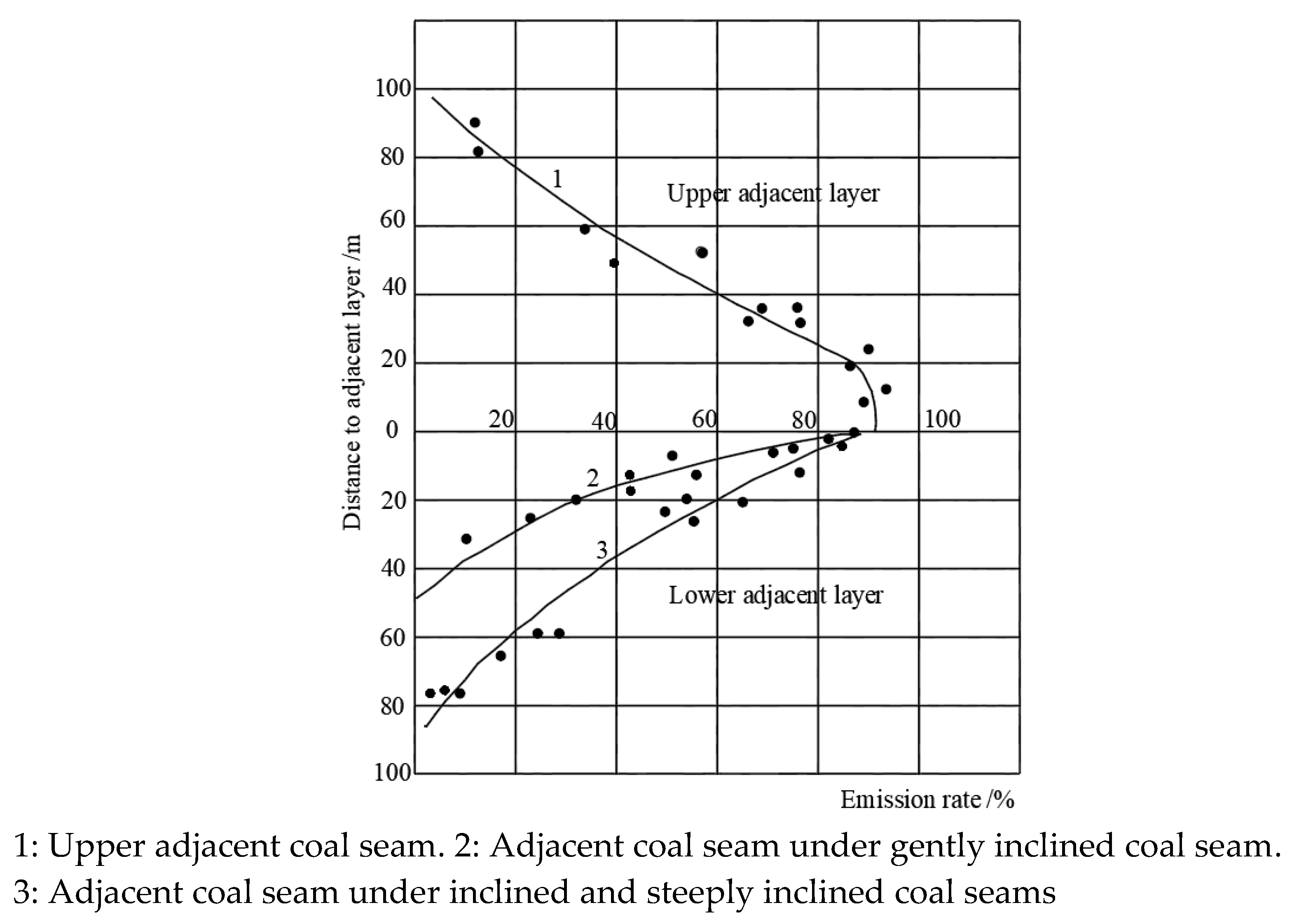
According to the standard AQ1018−2006 “mine gas emission prediction method” middle spacing and adjacent coal seam emission rate relationship curve [29], the Ding5−6 coal seam and Wu9−10 coal seam gas will pour into the Wu8 coal seam, other coal seam gas will not pour into the Wu8 coal seam. Therefore, desorption gas is collected in the Ding5−6 coal seam, the Wu8 coal seam, and the Wu9−10 coal seam, respectively, to determine the gas composition and hydrocarbon isotope values, including 13C (CH4), 13C (CO2), 13C (C2H6), and 2H (CH4). Four samples are collected from each coal seam, and a total of twelve samples are collected.
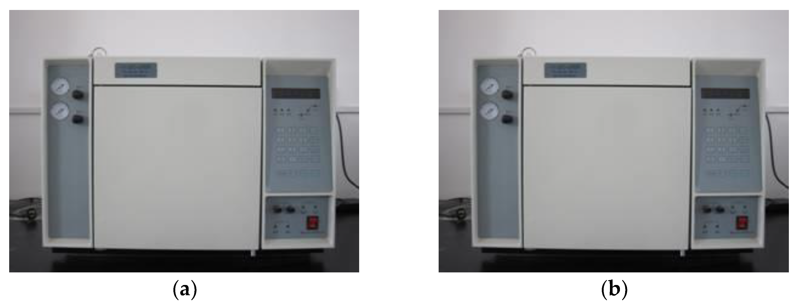
The specific test method is as follows: first, six sealed tanks with a capacity of 1 L should be prepared, the sealed tank should be washed and dried before use, and the air tightness of the sealed tank should be ensured to be intact, so there is no air leakage at 300 to 400 kPa; then the coal sample containing gas is drilled by the special drilling rig for coal core in the selected place of the coal mine, and the coal sample is put into the prepared sealed tank; after leaving the well, the sealed tank is connected with the experimental equipment for gas component test and hydrocarbon isotope value test. The instrument used for the gas component test is the GC−2000 TCD gas chromatograph, and the instrument used for the hydrocarbon isotope value test is the Delta V stable isotope mass spectrometer. The experimental instruments are shown in Figure 2.

2.2.3. Testing of CH4 Hydrocarbon Isotope Value of Mixed Gas in the Working Face

(1)
Working face mixed gas CH4 hydrocarbon isotope value determination scheme
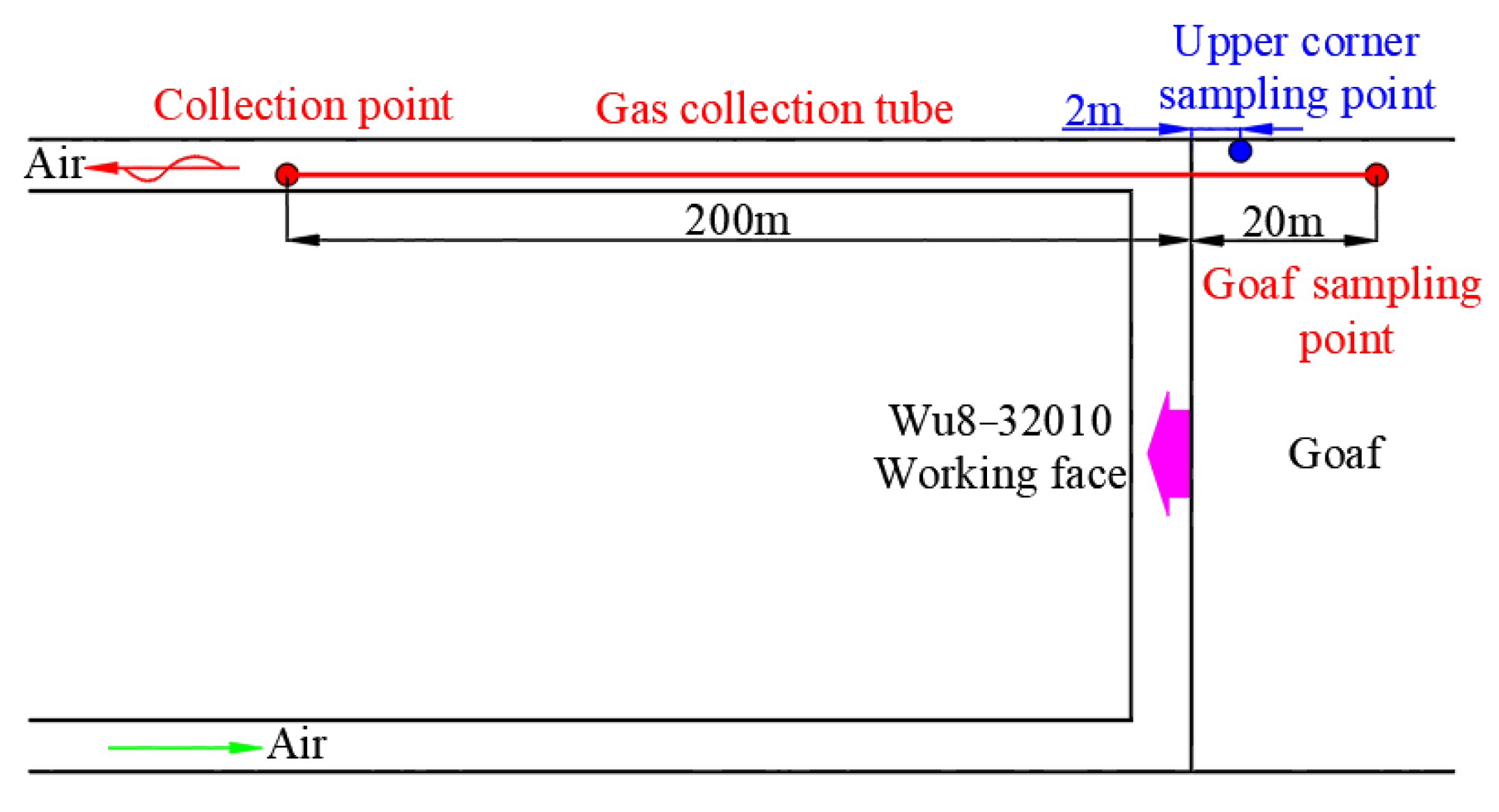
The two areas of the upper corner and goaf of the Wu8−32010 working face are selected as the sampling sites of mixed gas samples, in which the sampling point of the goaf is 20 m deep into the goaf. The specific sampling site is shown in Figure 3. The sampling time is calculated from the beginning of the working face, and the sampling time is one month, that is, from 7 June 2018 to 6 July 2018. The samples are collected once a day after the samples are collected, and the samples are sent to the laboratory for mixed gas component test and CH4 hydrocarbon isotope value test. During this period, a total of 30 groups of mixed gas samples are collected.
(2)
Sample collection method of mixed gas
The collection method of mixed gas samples in the upper corner of the working face is as follows: the sampling personnel stands on the footplate of the end support of the return air side and extends the expansion rod to a distance of 1.5 to 2 m from the support and a distance of 300 mm from the top side; the other end of the telescopic rod is connected with a high negative pressure suction tube, the gas in the sampling tube and the airbag is discharged, and the sampling bag is connected to start sampling. It is strictly prohibited to extend the head into the windshield during sampling.
The collection method of mixed gas samples in goaf is as follows: the sampling tube with a diameter of 20 mm is arranged in the return airway; one end of the sampling tube is 20 m deep into the goaf and a sampling device is arranged; the other end is connected to the extraction system in the return air trough, and the valve is set when connected to facilitate sampling.

3. Results

3.1. Test Results of Hydrocarbon Isotope Value of Gas in Each Coal Seam

The test results of gas composition and hydrocarbon isotope value of each coal seam are shown in Table 1. From Table 1, it can be seen that CH4 is the main gas component of each coal seam, among which the average proportion of CH4 gas component in the Ding5−6 coal seam is 71.563%, the average proportion of CH4 gas component in Wu8 coal seam is 87.340%, and the average proportion of CH4 gas component in the Wu9−10 coal seam is 88.642%, which indicates that there are some differences in CH4 gas components in each coal seam. In addition to CH4, the gas composition of each coal seam also includes N2, CO2, and C2H6.
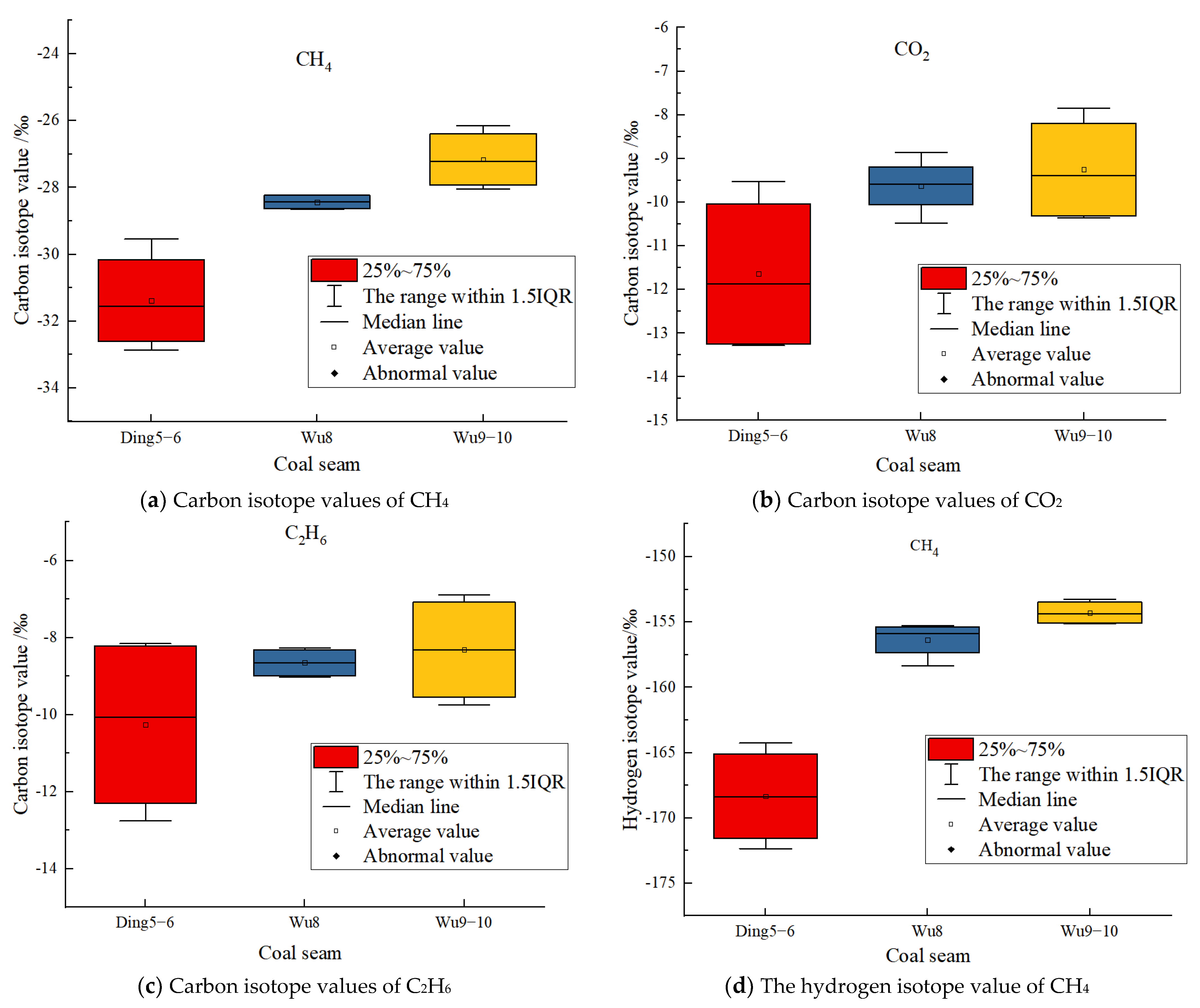
In order to more intuitively show the distribution characteristics of hydrocarbon isotope values of gas in each coal seam, the tested hydrocarbon isotope values are presented in a box diagram (Figure 4), the upper and lower bounds of the box represent 75% and 25% quantiles of the data, respectively, and the hollow point in the middle of the box represents the average value of the data, while the upper and lower bounds of the vertical lines represent the maximum and minimum values of the data, respectively.
It can be seen from Figure 4a that the distribution range (25% to 75%) of the carbon isotope values of CH4 gas in each coal seam does not overlap, so the carbon isotope value of CH4 gas has the condition to identify the source of mixed gas emission. It can be seen from Figure 4b that the distribution range (25% to 75%) of the carbon isotope values of CO2 gas in the Wu8 coal seam and the Wu9−10 coal seam overlaps, so the carbon isotope value of CO2 gas does not have the condition to identify the source of mixed gas emission. It can be seen from Figure 4c that the distribution range (25% to 75%) of carbon isotope values of C2H6 gas in the Ding5−6 coal seam, the Wu8 coal seam, and the Wu9−10 coal seam overlaps, so the carbon isotope values of C2H6 gas does not have the condition to identify the source of mixed gas emission. It can be seen from Figure 4d that the distribution range (25% to 75%) of hydrogen isotope values of CH4 gas in each coal seam does not overlap, so the hydrogen isotope value of CH4 gas has the condition to identify the source of mixed gas emission. Based on the above analysis, the hydrocarbon isotope value of CH4 gas can be selected to identify the source of mixed gas emission.

3.2. Test Results of Mixed Gas Emission Source in the Working Face

The working face mixed gas CH4 hydrocarbon isotope value test results are shown in Table 2.
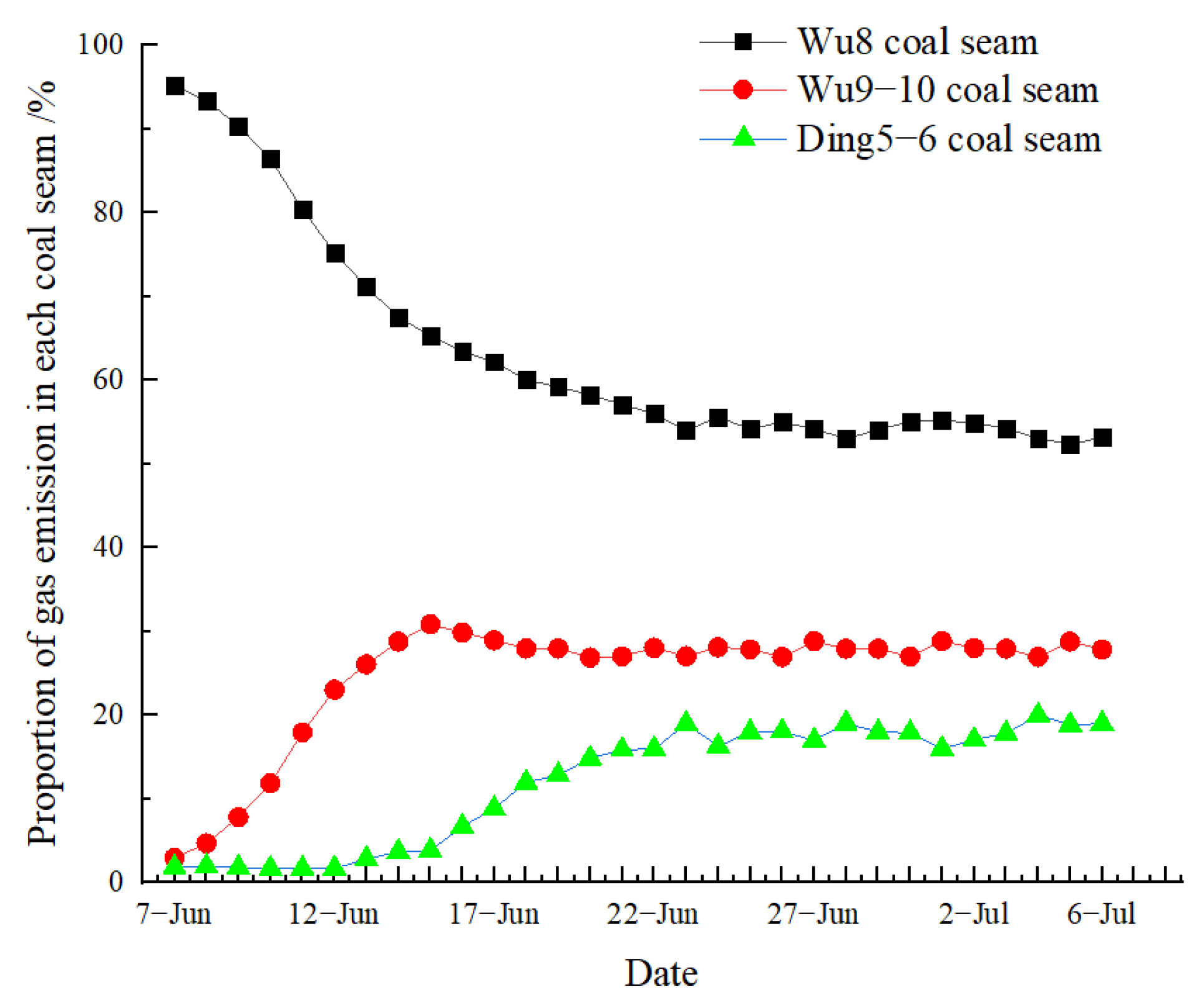
We substitute the test results of CH4 hydrocarbon isotope values in Table 1 and Table 2 into Equation (2), and use MATLAB software to obtain the proportion of gas emission from each coal seam in the upper corner and goaf during the mining process of the working face (Figure 5 and Figure 6). From Figure 5 and Figure 6, it can be seen that the change trend of gas emission proportion of each coal seam in the upper corner and goaf during the mining process of the working face is basically the same. The gas emission proportion of the Wu8 coal seam shows a change rule of decreasing first and then stabilizing, and the gas emission proportion of the Wu9−10 coal seam and the Ding5−6 coal seam shows a change rule of increasing first and then stabilizing.
Further analysis of Figure 5 and Figure 6 shows that the change law of the proportion of gas emission in each coal seam can be divided into three stages: the dominant stage of gas emission in the mining layer (stage I), the stage of gas emission in long-distance adjacent coal seams (stage II), and the dynamic equilibrium stage of gas emission in each coal seam (stage III).
The mining time of the stage I working face is from 7 June to 15 June, and the advancing distance of the working face is 54 m. The proportion of gas emission in the Wu8 coal seam shows a trend of rapid decline, and the proportion of gas emission decreases from 95% at the beginning of mining to 60%; the proportion of gas emission in the Wu9−10 coal seam shows a trend of rapid increase, and the proportion of gas emission increases from 3% at the beginning of mining to 30%; the proportion of gas emission in the Ding5−6 coal seam shows a trend of slow increase, and the proportion of gas emission increases from 1% at the beginning of mining to 5%.
The mining time of the stage II working face is from 16 June to 22 June, and the advancing distance of the working face is 42 m. The proportion of gas emission in the Wu8 coal seam shows a trend of slow decline, and the proportion of gas emission decreases from 60% to 53%; the proportion of gas emission in the Wu9−10 coal seam shows a slow downward trend, and the proportion of gas emission decreases from 30% to 27%; the proportion of gas emission in the Ding5−6 coal seam increases rapidly from 5% to 18%.
The mining time of the stage III working face is from 23 June to 6 July, and the advance distance of the working face is 84 m. The proportion of gas emission in each coal seam enters the dynamic equilibrium stage. The proportion of gas emission in the Wu8 coal seam is stable at about 54%, the proportion of gas emission in the Wu9−10 coal seam is stable at about 28%, and the proportion of gas emission in the Ding5−6 coal seam is stable at about 18%.

4. Discussion

4.1. Gas Emission Law of the Working Face and Each Coal Seam

While testing the CH4 hydrocarbon isotope value of the working face, the gas concentration value in the return airflow of the working face is recorded. Combining this with the test results of the air volume of the working face and the gas emission ratio of each coal seam in the upper corner, the gas emission of each coal seam can be obtained (Table 3).
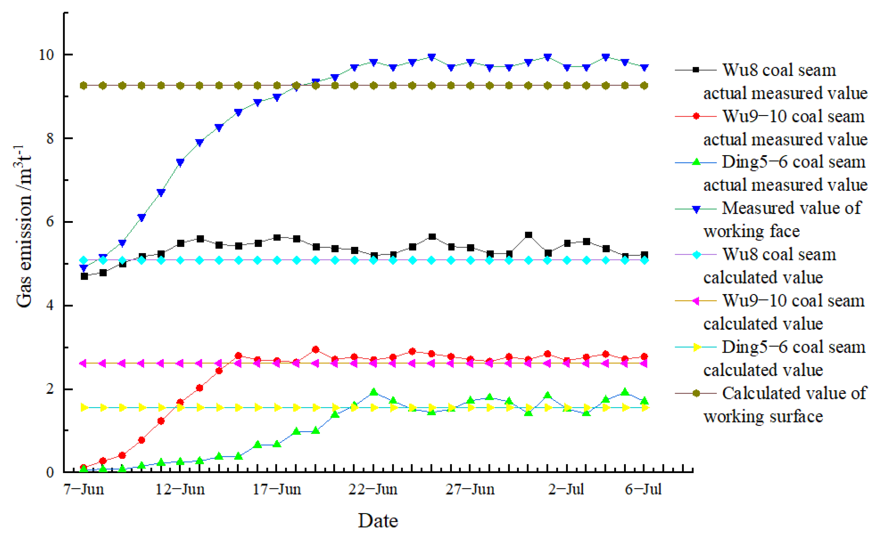
Based on the basic parameters of the working face, the “mine gas emission prediction method” (AQ1018−2006) is used to calculate the gas emission of the working face. Combining this with the gas emission test results of each coal seam in Table 3, the change trend of the measured value and the calculated value of the gas emission can be obtained (Figure 7).
The measured value in Figure 7 is the test result using the method in this paper, and the calculated value is the calculated result using the “mine gas emission prediction method” (AQ1018−2006). It can be seen from Figure 7 that the gas emission of each coal seam and working face has different variation rules. During the mining process of the working face, the gas emission of the Wu8 coal seam is maintained in a small fluctuation state, and the difference between the measured value and the calculated value is small. From the beginning of mining to 15 June, the gas emission of the Wu9−10 coal seam increases rapidly, after 15 June, the gas emission of the Wu9−10 coal seam remains in a small fluctuation state when it reaches the calculated value. From the beginning of mining to 15 June, the gas emission of the Ding5−6 coal seam increases slowly, from 15 June to 22 June, the gas emission of the Ding5−6 coal seam increases rapidly, and remains in a slight fluctuation state after reaching the calculated value. The mixed gas emission of the working face increases rapidly before 22 June and remains in a small fluctuation state after reaching the calculated value.
In summary, it can be seen that the gas emission amount of the working face and the measured value of the gas emission amount of each coal seam show an increasing trend in the early stage of the working face mining. The change range and change time of the gas emission amount are related to the geological conditions of the working face mining. The existing gas emission prediction method [30,31] makes it difficult to dynamically display and describe this change law; when the working face advances for a certain distance, the measured values of the gas emission amount of the working face and the gas emission amount of each coal seam will remain in a small fluctuation state. This small fluctuation state actually reflects the dynamic changes in coal seam mining conditions and geological conditions. The existing gas emission prediction method [32,33] usually cannot show this small fluctuation state. From the test results, it can be seen that the measured gas emission in this paper shows a small fluctuation state, which indicates that the mining conditions and geological conditions of the working face in this paper change little; however, in some cases, the changes of coal seam mining conditions and geological conditions are more intense, at this time, the gas emission will also fluctuate greatly, which will bring serious hidden dangers to the safe production of coal mines. Through the test method in this paper, the dynamic change law of gas emission in each coal seam can be obtained, so as to formulate and implement gas control measures in a targeted manner and avoid the occurrence of coal mine safety production accidents.

4.2. Analysis of Influencing Factors of Gas Emission

4.2.1. Analysis of Influencing Factors of Gas Emission in the Mining Layer

According to the standard “mine gas emission prediction method” (AQ1018 –2006), the calculation method of the mining layer gas emission is as follows:
Q 1 = K 1 K 2 K 3 m M ( W 0 W c )
where Q1 is the relative gas emission of the mining coal seam (including surrounding rock), m3/t; K1 is the gas emission coefficient of the surrounding rock, and the value range is 1.1 to 1.3. When the roof is managed by all caving methods, 1.3 is taken; K2 is the coal loss coefficient of the working face, which is the reciprocal of the recovery rate of the working face; K3 is the influence coefficient of roadway pre-drainage gas on gas emission in mining layer; m is the thickness of mining layer, m; M is the mining height of the working face, m; W0 is the original gas content of coal seam, m3/t; Wc is the residual gas content of coal seam, m3/t.
The calculation method of K3 is as follows:
K 3 = L 2 h L
where L is the length of the mining face, m; h is the width of the coal seam gas emission zone in the roadway, m, which is considered according to the average exposure time of 200 days in the roadway.
It can be seen from Equation (3) that the gas emission of the mining layer is related to the gas emission coefficient of the surrounding rock, the coal loss coefficient of the working face, the influence coefficient of the pre −drainage gas of the preparation roadway, and the original gas content of the coal seam. In the test of this paper, the basic parameters such as the gas emission coefficient of surrounding rock, the coal loss coefficient of the working face, the influence coefficient of pre-discharge gas in preparation roadway, and the original gas content of coal seam do not change, so the gas emission of mining layer remains in a small fluctuation state and the difference between the measured value and the calculated value is small (Figure 7).

4.2.2. Analysis of Influencing Factors of Gas Emission in Adjacent Coal Seam

The standard “mine gas emission prediction method” (AQ1018 –2006) also gives the adjacent coal seam gas emission calculation method as follows:
Q 2 = i = 1 n ( W 0 i W c i ) m i M η i
where Q2 is the relative gas emission of the adjacent coal seam, m3/t; mi is the thickness of the ith adjacent coal seam, m; M is the mining thickness of the mining layer, m; W0i is the original gas content of the ith adjacent coal seam, m3/t; Wci is the residual gas content of the ith adjacent coal seam, m3/t; η i is the ith adjacent coal seam gas emission rate, %, which can be seen in Figure 8.
Equation (5) is a common method for calculating the gas emission of adjacent coal seams [34]. According to Equation (5), the gas emission of adjacent coal seams is positively correlated with the original gas content of adjacent coal seams, the thickness of adjacent coal seams, and the gas emission rate of adjacent coal seams. In the process of working face mining, the original gas content of the adjacent coal seam, the thickness of the adjacent coal seam, and other parameters remain unchanged, they have no effect on the change of gas emission of the adjacent coal seam, so the gas emission rate of the adjacent coal seam is the main parameter affecting the change of gas emission of the adjacent coal seam. When using Equation (5) to calculate the gas emission of adjacent coal seams, the gas emission rate of adjacent coal seams is usually selected from Figure 8; however, the gas emission rate of adjacent coal seams in Figure 8 is the gas emission rate when the dynamic equilibrium stage is reached after the full mining of the working face. Before the dynamic equilibrium stage is reached, the calculation of the gas emission rate of adjacent coal seams in Figure 8 will inevitably produce large errors, which is the problem with using Equation (5) to calculate the gas emission of adjacent coal seams.
The gas emission rate of adjacent coal seams is related to the gas flow characteristics of adjacent coal seams. The principle of adjacent coal seam gas flowing to the working face is (Figure 9): after the mining of the mining layer, a certain mining space will be formed, the coal rock layer around the coal seam will move to the mining space, and the original equilibrium relationship of the coal rock mass will be disturbed and destroyed, so that the original stress–strain state of the coal rock mass will change. The results of the change will lead to the release of pressure and elastic potential energy in the coal rock around the coal seam, thus forming mining fractures in the coal rock around the coal seam. As an associated gas of the coal seam, the gas itself has fluidity, and the generation of mining cracks will provide a channel for the seepage movement of gas in the coal seam. During the mining process of the mining layer, the pressure-relief gas of the adjacent coal seam flows into the mining face through the mining-induced cracks, which increases the gas emission of the mining face [35].
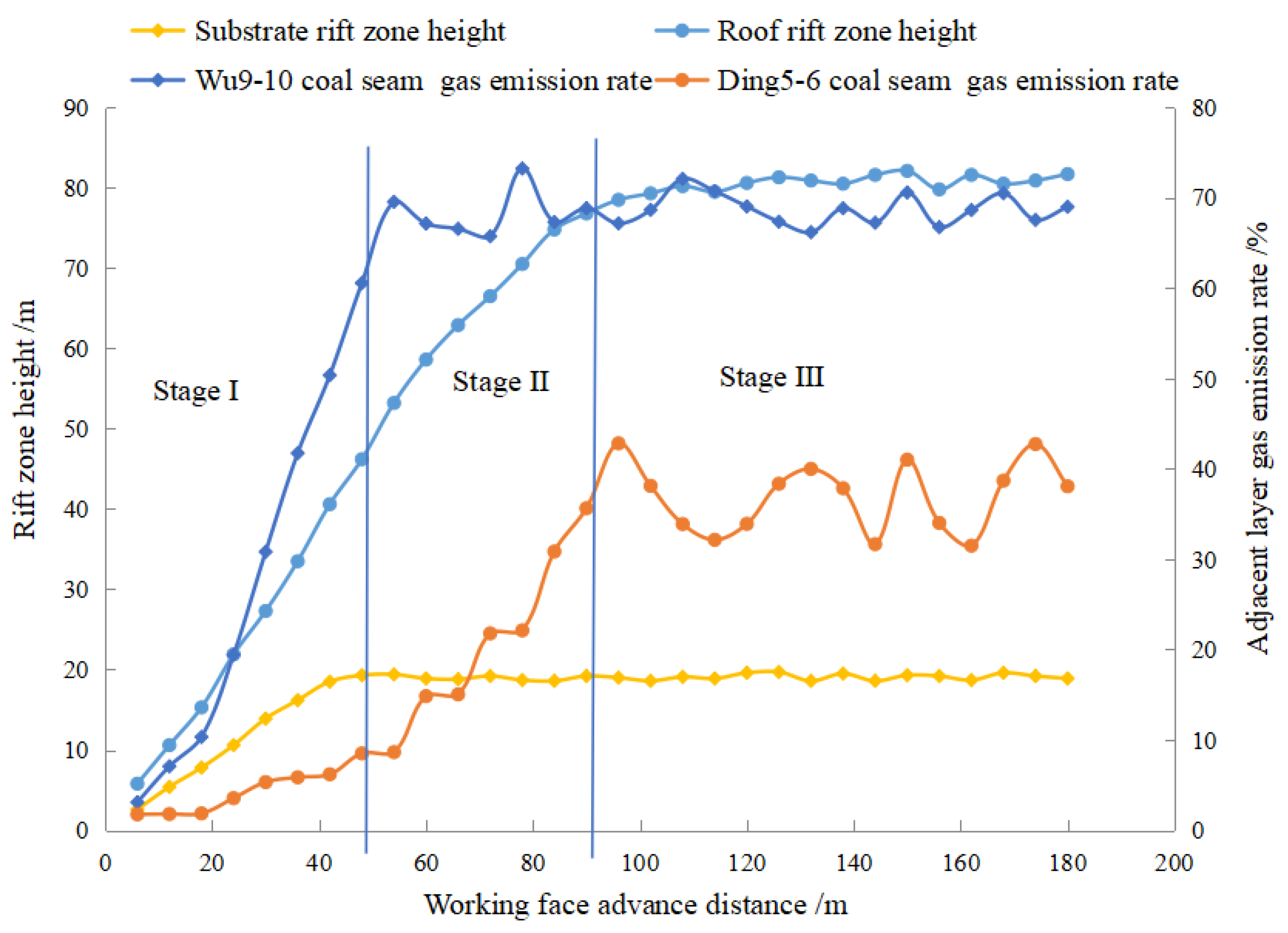
In order to further analyze the influence of the gas emission rate of the adjacent coal seam on the gas emission of the adjacent coal seam, based on the geological conditions of this paper, FLAC3D software is used to simulate the development characteristics of the fracture zone in the process of the working face advancing. According to the numerical simulation results, the change trend of the development height of the mining fracture zone with the advancing distance of the working face can be obtained. Then the adjacent coal seam gas emission rate is calculated according to Equation (5) by using the measured data of the adjacent coal seam gas emission (Figure 10).
It can be seen from Figure 10 that the height of the mining fracture zone increases with the advance of the working face. The height of the fracture zone increases rapidly in the early stage of mining, and the growth rate slows down after full mining; when the working face advances to a certain distance, the height of fracture zone does not increase anymore. It can also be seen in Figure 10 that the adjacent coal seam gas emission rate is a dynamic change parameter in the working face mining process.
Based on the test results of this paper, combined with Figure 9 and Figure 10, the influence of the gas emission rate of adjacent coal seams on gas emission of adjacent coal seams can be analyzed as follows:
(1)
In the process of advancing the working face, the height of the mining-induced fracture zone of the coal seam roof and the coal seam floor in stage I shows an increasing trend. Due to the small interlayer spacing between the Wu8 coal seam and the Wu9 –10 coal seam, the Wu9−10 coal seam quickly enters the mining-induced fracture zone of the coal seam floor, so that a large amount of gas in the Wu9−10 coal seam enters the working face through the mining-induced fracture zone of the coal seam floor, resulting in a rapid increase in the gas emission rate of the Wu9−10 coal seam. Although the height of the mining fracture zone of the coal seam roof increases rapidly, due to the large interlayer spacing between the Wu8 coal seam and the Ding5−6 coal seam, the Ding5−6 coal seam has not yet entered the mining fracture zone of the coal seam roof, so that only a small amount of the Ding5−6 coal seam gas enters the working face, so the gas emission rate of the Ding5−6 coal seam increases slowly.
(2)
In the process of advancing the working face, the height of the mining-induced fracture zone of the coal seam floor in stage II tends to be stable. Because the coal seam of Wu9−10 has entered the mining-induced fracture zone of the coal seam floor in stage I, the gas of the Wu9−10 coal seam entering the working face in stage II will remain in a small fluctuation state, resulting in the gas emission rate of the Wu9−10 coal seam also remaining in a small fluctuation state. In stage II, the height of the mining fracture zone of the coal seam roof is still increasing. With the increase of the height of the mining fracture zone of the coal seam roof, the Ding5−6 coal seam will enter the mining fracture zone of the coal seam roof, so that the gas of the Ding5−6 coal seam enters the working face through the mining fracture zone of the coal seam roof, resulting in the rapid increase of the gas emission rate of the Ding5−6 coal seam in stage II.
(3)
With the advance of the working face, in stage III, the mining-induced fracture zone height of the coal seam roof and floor tends to be stable. The Ding5−6 coal seam and the Wu9−10 coal seam also enter into the mining-induced fracture zone of the coal seam roof and floor, respectively, the gas emission rate of adjacent coal seams and the gas emission of adjacent coal seams will remain in a small fluctuation state until the end of working face mining.
According to the above analysis, the gas emission rate of adjacent coal seams in the process of the working face shows a phased change characteristic, which is the result of the combined effect of the working face mining method and geological conditions. Therefore, the gas emission of adjacent coal seams is the result of a combination of multiple factors, it is difficult to predict the gas emission of adjacent coal seams only by establishing a mathematical model or calculation formula [36,37,38], and there will be obvious defects in accuracy and timeliness.

4.3. Gas Emission Rate of Adjacent Coal Seams

In Section 4.2., the influencing factors and changing trends of the gas emission rate of adjacent coal seams have been analyzed. Because the gas emission rate of adjacent coal seams shows a phased change during the mining process of the working face, the calculation formula for the gas emission rate of adjacent coal seams will also be established in stages.
Firstly, according to Figure 11, the calculation formula of the height of the fracture zone of the coal seam roof with the advancing distance of the working face is obtained by fitting:
h 1 = 0.004 l 2 + 1.337 l 5.884 ( R 2 = 0.994 ) l l 1
where l is the advancing distance of the working face, m; h1 is the height of the coal seam roof fracture zone, m; l1 is the advancing distance of the working face when the height of the fracture zone of the coal seam roof reaches the upper adjacent coal seam, m.
Similarly, according to Figure 11, the calculation formula of the height of the fracture zone in the coal seam floor with the advancing distance of the working face is obtained by fitting:
h 2 = 0.002 l 2 + 0.572 l 1.055 ( R 2 = 0.994 ) l l 2
where l is the advancing distance of the working face, m; h2 is the height of the coal seam floor fracture zone, m; l2 is the advancing distance of the working face when the height of the fracture zone of the coal seam floor reaches the lower adjacent coal seam, m.
Then, according to Figure 11, the calculation formula of the gas emission rate of the upper adjacent coal seam with the height of the coal seam roof fracture zone is obtained by fitting:
P 1 = 1.236 e 0.042 h 1 ( R 2 = 0.98 ) l l 1
where P1 is the upper adjacent coal seam gas emission rate, %.
Similarly, according to Figure 11, the calculation formula of the gas emission rate of the lower adjacent coal seam with the height of the fracture zone of the coal seam floor is obtained by fitting:
P 2 = 2.609 e 0.168 h 2 ( R 2 = 0.976 ) l l 2
where P2 is the gas emission rate of the lower adjacent coal seam, %.
According to the gas flow characteristics of the adjacent coal seam during the advancing process of the working face, the higher the height of the mining fracture zone, the higher the gas emission rate of the adjacent coal seam, and the gas emission rate of the adjacent coal seam and the height of the mining fracture zone are exponentially related. From the layer spacing of adjacent coal seams, the smaller the layer spacing of adjacent coal seams, the higher the gas emission rate of adjacent coal seams, and the layer spacing of adjacent coal seams is inversely proportional to the gas emission rate of adjacent coal seams. In addition, it can be seen from Equations (8) and (9) that the gas emission rates of upper adjacent coal seams and lower adjacent coal seams have similar variation trends with the height of the fracture zone, and the gas emission rates of upper adjacent coal seams and lower adjacent coal seams can be combined for study.
Based on the above analysis, combined with Equation (6)–(9) and Figure 8, the calculation formula of the gas emission rate of the upper adjacent coal seam with the advancing distance of the working face can be obtained by introducing the interlayer spacing H1 of the upper adjacent coal seam and the interlayer spacing H2 of the lower adjacent coal seam:
h 1 = 0.004 l 2 + 1.337 l 5.884 ( R 2 = 0.994 ) l l 1 P 1 = ( - 0.024 ) H 1 - 16 ( + 2.609 ) e ( 0.00218 ( H 1 - 16 ) + 0.168 ) h 1 l l 1 P 1 = ( 115 H 1 ) / 115 l > l 1
where H1 is the distance between the upper adjacent coal seam and the mining layer, m.
Similarly, the calculation formula of the gas emission rate of the lower adjacent coal seam with the advancing distance of the working face can be obtained:
h 2 = 0.002 l 2 + 0.572 l 1.055 ( R 2 = 0.994 ) l l 2 P 2 = ( - 0.024 ) H 2 - 16 ( + 2.609 ) e ( 0.00218 ( H 2 - 16 ) + 0.168 ) h 2 l l 2 P 2 = ( 50 H 2 ) / 50 l > l 2
where H2 is the distance between the lower adjacent coal seam and the mining layer, m.
According to Equations (10) and (11), the variation trend of the gas emission rate of adjacent coal seams with the advancing distance of the working face can be drawn under different interlayer spacings (Figure 11 and Figure 12). From Figure 11 and Figure 12 it can be seen that as the working face advances, the gas emission rate of the upper adjacent coal seam and the lower adjacent coal seam has the same change trend. In the early stage of working face mining, the gas emission rate of adjacent coal seams increases exponentially with the advancing distance of the working face. After the working face is fully mined, the gas emission rate of adjacent coal seams remains stable; the larger the layer spacing with the mining coal seam is, the smaller the gas emission rate of the adjacent coal seam is and the longer the distance for the working face to reach the dynamic equilibrium state. In Figure 11 and Figure 12, the curve of seam gas emission rate of adjacent coal seam with an interlayer spacing of 74 m and the curve of seam gas emission rate of adjacent coal seam of the Ding5 –6 coal seam basically coincide, and the curve of seam gas emission rate of adjacent coal seam with an interlayer spacing of 16 m and the curve of seam gas emission rate of adjacent coal seam of Wu9−10 coal seam basically coincide. This shows that the error between the calculated value and the test result is small, and the accuracy of the gas emission rate of adjacent coal seam calculated by Equations (10) and (11) is high, which can meet the needs of gas emission prediction of the adjacent coal seam in production practice.
The test method of gas emission in adjacent coal seams and the calculation formula of the gas emission rate in adjacent coal seams proposed in this paper can make up for the shortcomings of the existing methods, and have good applicability under complex geological conditions. Its popularization and application under the complex geological conditions of multiple coal seams can obtain considerable safety and economic benefits.

5. Conclusions

  • The CH4 hydrocarbon isotope values in the gas of the Wu8 coal seam, the Wu9−10 coal seam, and the Ding5−6 coal seam are obviously different, which has the conditions to identify the source of gas emission in the working face by using the hydrocarbon isotope method.
  • The variation law of the proportion of gas emission in each coal seam during the mining process of the working face can be divided into the dominant stage of gas emission in the mining layer (stage I), the stage of gas emission in the long-distance adjacent coal seam (stage II), and the dynamic equilibrium stage of gas emission in each coal seam (stage III). The proportion of gas emission in the Wu8 coal seam decreases from 95% to 60% in stage I, from 60% to 53% in stage II, and stabilizes at about 54% in stage III. The proportion of gas emission in the Wu9−10 coal seam increases from 3% to 30% in stage I, decreases from 30% to 27% in stage II, and stabilizes at about 28% in stage III. The proportion of gas emission in the Ding5−6 coal seam increases from 1% to 5% in stage I, from 5% to 18% in stage II, and stabilizes at about 18% in stage III.
  • During the mining process of the working face, the gas emission amount of the Wu8 coal seam remains in a stable state. The gas emission amount of the Wu9−10 coal seam increases rapidly in stage I and remains stable in stage II and stage III. The gas emission amount of the Ding5−6 coal seam increases slowly in stage I, increases rapidly in stage II, and remains stable in stage III. The mixed gas emission of the working face increases rapidly in stage I and stage II and remains stable in stage III.
  • The adjacent coal seam gas emission rate is the main influencing factor of the adjacent coal seam gas emission, and the adjacent coal seam gas emission rate is related to the development process of the mining fracture zone. When the height of the mining fracture zone increases, the gas emission rate of the adjacent coal seam increases exponentially, and the gas emission of the working face increases. After the height of the mining fracture zone tends to be stable, the gas emission rate of adjacent coal seams and the gas emission amount of each coal seam remain in a small fluctuation state.
  • The calculation formula of the gas emission rate of the adjacent coal seam is established. Compared with the test results, the error of the calculated value is small, which can meet the needs of gas emission prediction of adjacent coal seams in production practice.

Author Contributions

Conceptualization, G.X. and Y.H.; Data curation, G.X., Y.H. and Z.W.; Formal analysis, G.X., Y.H. and H.J.; Funding acquisition, G.X., Z.W. and H.J.; Methodology, G.X. and Y.H.; Project administration, H.J.; Software, G.X., Y.H. and Z.W.; Supervision, H.J.; Writing—original draft, G.X. and Y.H.; Writing—review and editing, G.X., H.J., Y.H. and Z.W. All authors have read and agreed to the published version of the manuscript.

Funding

All of these are gratefully acknowledged. This work was financially supported by the Natural Science Foundation of China (51904231), the National Key Research and Development Program (2018YFC0807805), and the Natural Science Basic Research Program of Shaanxi (2019JM-072).

Institutional Review Board Statement

Not applicable.

Informed Consent Statement

Not applicable.

Data Availability Statement

Not applicable.

Acknowledgments

Many thanks to all the contributions and support given by the authors in preparing the writing of this article. Moreover, thanks to the Sixth Mine of Pingdingshan Tian’an Coal Co., Ltd. for providing the field test for this study.

Conflicts of Interest

The authors declare no conflict of interest.

References

  1. Kurnia, J.C.; Xu, P.; Sasmito, A.P. A novel concept of enhanced gas recovery strategy from ventilation air methane in underground coal mines –A computational investigation. J. Nat. Gas Sci. Eng. 2016, 35, 661–672. [Google Scholar] [CrossRef]
  2. Mishra, D.P.; Panigrahi, D.D.; Kumar, P. Computational investigation on effects of geo-mining parameters on layering and dispersion of methane in underground coal mines –A case study of Moonidih Colliery. J. Nat. Gas Sci. Eng. 2018, 56, 110–124. [Google Scholar] [CrossRef]
  3. Karacan, C.Ö.; Diamond, W.P.; Schatzel, S.J. Numerical analysis of the influence of in-seam horizontal methane drainage boreholes on longwall face emission rates. Int. J. Coal Geol. 2007, 72, 15–32. [Google Scholar] [CrossRef]
  4. Sander, R.; Connell, L.D. A probabilistic assessment of enhanced coal mine methane drainage (ECMM) as a fugitive emission reduction strategy for open cut coal mines. Int. J. Coal Geol. 2014, 131, 288–303. [Google Scholar] [CrossRef]
  5. Qi, Q.J.; Xia, S.Y. Construction of sharing platform for the gas emission rate prediction based on source prediction. Min. Saf. Environ. Prot. 2018, 45, 59–64. [Google Scholar]
  6. Cang, Y.X.; Li, W.G.; Shu, Z.C.; Yan, C.Y. Statistical analysis on coal mine gas explosion and optimization of safety input. Adv. Mater. Resea. 2011, 1043, 1316–1321. [Google Scholar]
  7. Gas Geology Group of Jiaozuo Mining Institute. Attempt of statistical analysis in prediction of gas outburst. Coalfield Geol. Explo. 1983, 26–30+8. [Google Scholar]
  8. Lunarzewski, W.L. Gas emission prediction and recovery in underground coal mines. Int. J. Coal Geol. 1998, 35, 117–145. [Google Scholar] [CrossRef]
  9. Zhang, Y.P.; Ye, Q.; Jia, Z.Z.; Jiang, W.W. The analysis and forecast of gas emission in workface. China Min. J. 2007, 123, 46–49+52. [Google Scholar]
  10. Whittles, D.N.; Lowndes, I.S.; Kingman, S.W.; Yates, C.; Jobling, S. Influence of geotechnical factors on gas flow experienced in a UK longwall coal mine panel. Int. J. Rock Mech. Min. 2006, 43, 369–387. [Google Scholar] [CrossRef]
  11. Gu, S.; Cui, H.Q.; Feng, W.L. Mine gas gushing forecasting based on grey model and wavelet neural network. J. China Coal Soc. 2007, 156, 964–966. [Google Scholar]
  12. Zhang, S.R.; Wang, B.T.; Li, X.E.; Chen, H. Research and application of improved gas concentration prediction model based on grey theory and BP neural network in digital mine. Procedia CIRP 2016, 56, 471–475. [Google Scholar] [CrossRef] [Green Version]
  13. Zhang, X.L.; Shan, J.P.; Peng, S.P. Mathematical geology technique and method for prediction of gas content and emission. J. China Coal Soc. 2009, 34, 350–354. [Google Scholar]
  14. Ock, J.H. Activity duration quantification under uncertainty: Fuzzy set theory application. Cost Eng. 1996, 38, 26. [Google Scholar]
  15. Xiao, J.P.; Dai, G.L. Study on different-source prediction of gas emission in fully mechanized coal face based on BP neural network. J. Anhui Univ. Sci. and Techno. 2011, 31, 51–55. [Google Scholar]
  16. Zhu, H.Q.; Chang, W.J.; Zhang, B. Different-source gas emission prediction model of working face based on BP artificial neural network and its application. J. China Coal Soc. 2007, 152, 504–508. [Google Scholar]
  17. Xu, Q.Y.; Zhang, L.; Li, Y.M. Fully mechanized working face gas distribution law and constitution characteristics in BU Ertai coal mine. J. Liaoning Techni. Univ. 2014, 33, 887–891. [Google Scholar]
  18. Li, S.G.; Ding, Y.; An, Z.F.; Wei, W.B. Research on gas emission and distribution characteristics of fully Mechanized Coal Face in High Methane and Thick Seam. Coal Techno. 2015, 34, 113–116. [Google Scholar]
  19. Gao, L.; Li, X.J.; Pan, J.C. Main controlling factors and control measures of gas emission in mining face of Buertai mine. J. Saf. Sci. Techno. 2019, 15, 130–135. [Google Scholar]
  20. Zhang, P.; Wang, W.C. Research on gas emission and distribution of the first face in high gas and thick seam. Sci. Techno. Eng. 2017, 17, 176–180. [Google Scholar]
  21. Cui, H.L.; Wang, Y.; Zhao, H.B.; Zou, D.L. Distribution of gas emission at fully mechanized top coal caving face in high gas and super thick coal seam in xiagou mine. Saf. Coal Min. 2016, 47, 178–181. [Google Scholar]
  22. Yuan, L. Gas distribution of the mined-outside and extraction technology of first mined key seam relief-mining in gassy multi-seams of low permeability. J. China Coal Soc. 2008, 33, 1362–1367. [Google Scholar]
  23. Dai, G.L.; Wang, Y.Q.; Zhang, C.R.; Li, Q.M.; Shao, G.Y. Forecast of the gas effused form the face in protective seam. J. China Coal Soc. 2007, 32, 382–385. [Google Scholar]
  24. Wu, R.X.; Xiao, Y.L.; Fang, L.C. Geophysical and geochemical prospecting for hard heading gas abnormal places between high gas coal seams. Coal Geol. China. 2014, 26, 74–77. [Google Scholar]
  25. Huang, H.; Jiang, F.W.; Han, B.W.; Zhang, P.S. Comprehensive detection analysis on the reason of abnormal gas blow-out from the drilling hole through the floor limestone of A group coal seam in Huainan mining area. J. China Coal Soc. 2013, 38, 1988–1992. [Google Scholar]
  26. Liang, W.X.; Li, J.T.; Fu, W.; Zhang, Y. Research and application of mixed gas source identification technology based on stable isotope. Min. Saf. Environ. Prot. 2022, 49, 56–61. [Google Scholar]
  27. Zhou, W.; Yuan, L.; Zhang, G.L.; Dou, H.L.; Xue, S.; He, G.H.; Han, Y.C. A new method for determining the individual sources of goaf gas emissions: A case study in Sihe Coal Mine. J. China Coal Soc. 2018, 43, 1016–1023. [Google Scholar]
  28. Yang, W.; Lin, B.Q.; Gao, Y.B.; Lv, Y.; Wang, Y.; Mao, X.; Wang, N.; Wang, D.; Wang, Y. Optimal coal discharge of hydraulic cutting inside coal seams for stimulating gas production: A case study in Pingmei coalfield. J. Nat. Gas Sci. Eng. 2016, 28, 379–388. [Google Scholar] [CrossRef]
  29. AQ1018 –2006. Prediction method of mine gas emission. Syst. Sci. Control. Eng. 2006, 6, 85–91. [Google Scholar]
  30. Qin, Y.J.; Su, W.W.; Jiang, W.Z.; Chen, Y.P. Research progress and development direction of mine gas emission forecast technology in china. Saf. Coal Min. 2020, 51, 52–59. [Google Scholar]
  31. Wang, L.; Li, J.H.; Zhang, W.B.; Li, Y. Research on the gas emission quantity prediction model of improved artificial bee colony algorithm and weighted least squares support vector machine (IABC-WLSSVM). Appl. Bionics Biomech. 2022, 2022, 4792988. [Google Scholar] [CrossRef]
  32. Xu, G.; Wang, L.; Jin, H.W.; Liu, P.D. Gas emission prediction in mining face by Factor Analysis and BP neural network coupling model. J. Xi’an Univ. Sci. Techno. 2019, 39, 965–971. [Google Scholar]
  33. Liu, C.; Li, S.; Yang, S. Gas emission quantity prediction and drainage technology of steeply inclined and extremely thick coal seams. Int. J. Min. Sci. Techno. 2018, 28, 415–422. [Google Scholar]
  34. Li, D.Y. Discussion on gas emission prediction method in adjacent layer of fully mechanized caving face. Coal Min. Saf. 2014, 45, 169–171. [Google Scholar]
  35. Wang, H.F.; Fang, L.; Cheng, Y.P.; Zhou, H.R. Pressure-relief gas extraction of lower adjacent coal seam based on strata movement and its application. J. Min. Saf. Eng. 2013, 30, 128–131. [Google Scholar]
  36. Liu, G.F.; Wang, H.X.; Song, Z.M. Numerical simulation study on gas emission rate owing to mining influence of adjacent coal seam. J. Heinan Polytechnic Univ. 2015, 34, 445–450. [Google Scholar]
  37. Wang, W.; Peng, L.; Wang, X. Prediction of coal mine gas emission quantity based on grey-gas geologic method. Math. Ppobl. Eng. 2018, 2018 Pt 17, 4397237. [Google Scholar]
  38. Qu, Q.D.; Balusu, R.; Belle, B. Specific gas emissions in Bowen Basin longwall mines, Australia. Int. J. Coal Geol. 2022, 261, 104076. [Google Scholar] [CrossRef]
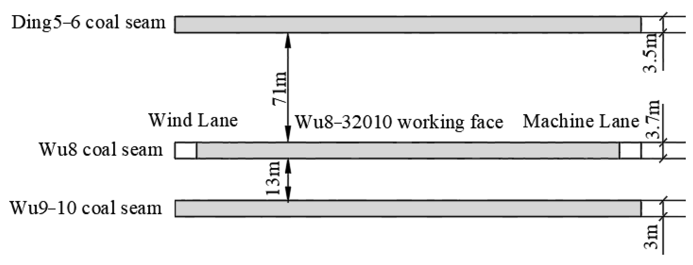
Figure 1. Wu8 −32010 working face strike section.
Energies 16 01225 g001
Figure 2. Experimental instrument diagram. (a) GC−2000TCD gas chromatograph. (b) Delta V stable isotope mass spectrometer.
Energies 16 01225 g002
Figure 3. Mixed gas sample collection location diagram.
Energies 16 01225 g003
Figure 4. Box diagram of hydrocarbon isotope value distribution of gas in each coal seam.
Energies 16 01225 g004
Figure 5. Gas emission proportion of each coal seam in the upper corner.
Energies 16 01225 g005
Figure 6. Gas emission proportion of each coal seam in goaf.
Energies 16 01225 g006
Figure 7. Variation trend of measured and calculated values of gas emission.
Energies 16 01225 g007
Figure 8. Relationship curve between gas emission rate of adjacent coal seam and layer spacing.
Energies 16 01225 g008
Figure 9. Gas flow characteristics of adjacent coal seams during advancing of the working face. (a) Unmined coal seams. (b) Stage I. (c) Stage II.
Energies 16 01225 g009
Figure 10. Variation of mining fracture zone height and gas emission rate of adjacent coal seams with the advancing distance of the working face.
Energies 16 01225 g010
Figure 11. Variation of the gas emission rate of lower adjacent coal seams with the advancing distance of the working face.
Energies 16 01225 g011
Figure 12. Variation of the gas emission rate of upper adjacent coal seams with the advancing distance of the working face.
Energies 16 01225 g012
Table 1. Test results of gas components and hydrocarbon isotope values of each coal seam.
Coal SeamSample NumberGas Component/%Carbon Isotope Values/‰Hydrogen Isotope Values/‰
CH4C2H6N2CO213C (CH4)13C (CO2)13C (C2H6)2H (CH4)
Ding5−6 coal seam173.2690.01517.269.456−32.335−13.210−8.152−164.257
270.4560.0120.4939.041−32.864−10.548−12.754−165.952
374.3870.01418.0317.568−29.543−9.526−11.853−172.346
468.140.00921.75210.099−30.790−13.284−8.265−170.765
Average value71.5630.01219.3849.041−31.383−11.642−10.256−168.33
Wu8 coal seam185.5620.02112.062.357−28.250−9.518−8.265−158.359
289.8430.0248.5411.592−28.652−10.475−8.351−155.458
389.4250.0168.6951.864−28.225−8.865−9.026−155.269
484.530.01113.4442.015−28.613−9.642−8.938−156.314
Average value87.3400.018.10.6851.957−28.435−9.625−8.645−156.35
Wu9−10 coal seam190.3650.028.2681.347−26.158−7.854−6.892−155.128
286.5250.0248.4694.982−28.045−8.526−7.264−153.284
388.9420.0289.2511.779−27.816−10.365−9.350−153.649
488.7360.029.2961.948−26.629−10.263−9.742−155.059
Average value88.6420.0238.8212.514−27.162−9.252−8.312−154.28
Table 2. Test results of CH4 hydrocarbon isotope value in the mixed gas of the working face.
Measurement LocationsIsotope Category7 June8 June9 June10 June11 June12 June13 June14 June15 June16 June
Upper corner13 C(CH4)/‰−24.778−24.756−24.742−24.676−24.610−24.579−24.557−24.502−24.482−24.425
2H(CH4)/‰−136.302−136.315−136.326−136.162−136.019−136.031−136.041−135.872−135.896−135.407
Goaf13C (CH4)/‰−24.769−24.753−24.733−24.705−24.659−24.620−24.570−24.529−24.509−24.449
2H(CH4)/‰−136.263−136.253−136.282−136.306−136.321−136.328−136.152−136.021−135.996−135.537
Measurement locationsIsotope category17 June18 June19 June20 June21 June22 June23 June24 June25 June26 June
Upper corner13C (CH4)/‰−24.430−24.366−24.343−24.270−24.227−24.161−24.200−24.243−24.273−24.245
2H(CH4)/‰−135.405−134.906−134.908−134.257−133.958−133.460−133.773−134.121−134.276−134.087
Goaf13C (CH4)/‰−24.405−24.339−24.318−24.278−24.253−24.243−24.179−24.235−24.197−24.202
2H(CH4)/‰−135.187−134.688−134.543−134.219−134.057−134.042−133.557−133.989−133.718−133.706
Measurement locationsIsotope category27 June28 June29 June30 June1 July2 July3 July4 July5 July6 July
Upper corner13C (CH4)/‰−24.209−24.187−24.202−24.282−24.178−24.251−24.273−24.203−24.161−24.199
2H(CH4)/‰−133.788−133.631−133.793−134.281−133.631−134.077−134.266−133.800−133.466−133.777
Goaf13C (CH4)/‰−24.213−24.171−24.196−24.205−24.237−24.217−24.200−24.156−24.168−24.173
2H(CH4)/‰−133.881−133.548−133.718−133.728−134.042−133.867−133.744−133.394−133.575−133.557
Table 3. Gas emission test results of each coal seam.
Date7 June8 June9 June10 June11 June12 June13 June14 June15 June16 June
Category
Gas concentration/%0.410.430.460.510.560.620.660.690.720.74
Wu8 coal seam gas emission/m3t−14.724.795.025.185.245.495.615.465.455.51
Wu9−10 coal seam gas emission/m3t−10.120.290.420.781.241.682.032.442.802.71
Ding5−6 coal seam gas emission/m3t−10.080.080.080.160.240.260.280.380.390.67
Working face gas emission/m3t−14.925.165.526.126.727.447.928.288.648.88
Date17 June18 June19 June20 June21 June22 June23 June24 June25 June26 June
Category
Gas concentration/%0.750.770.780.790.810.820.810.820.830.81
Wu8 coal seam gas emission/m3t−15.645.615.415.385.345.215.245.415.665.41
Wu9−10 coal seam gas emission/m3t−12.682.652.952.712.772.712.772.912.852.78
Ding5−6 coal seam gas emission/m3t−10.680.981.001.391.601.931.721.531.451.53
Working face gas emission/m3t−19.009.249.369.489.729.849.729.849.969.72
Date27 June28 June29 June30 June1 July2 July3 July4 July5 July6 July
Category
Gas concentration/%0.820.810.810.820.830.810.810.830.820.81
Wu8 coal seam gas emission/m3t−15.405.255.245.715.275.505.545.385.195.23
Wu9−10 coal seam gas emission/m3t−12.712.672.772.712.842.692.772.842.722.78
Ding5−6 coal seam gas emission/m3t−11.731.801.701.431.851.531.421.741.921.71
Working face gas emission/m3t−19.849.729.729.849.969.729.729.969.849.72
Disclaimer/Publisher’s Note: The statements, opinions and data contained in all publications are solely those of the individual author(s) and contributor(s) and not of MDPI and/or the editor(s). MDPI and/or the editor(s) disclaim responsibility for any injury to people or property resulting from any ideas, methods, instructions or products referred to in the content.