Abstract
A new pumpless liquid cooling system for a single-stage two-cylinder reciprocating compressor has been developed from the analysis of work processes and cooling systems of reciprocating compressors, where one piston compresses and moves gas and coolant in the cooling system. The intensification of the coolant movement increases in the machine, which can reduce the temperature of the cylinder–piston group and increase the indicator efficiency and the compressor feed rate. A mathematical model of working processes in a reciprocating compressor and its cooling system has been developed on the basic fundamental laws of conservation of energy, mass and motion. A prototype was developed and tested to obtain new knowledge about the processes in the machine and confirm the assumptions made while developing the mathematical model. After a series of experiments, the influence of cooling on the working processes in a reciprocating compressor, the technical work carried out in each working process, the energy and consumption characteristics of a reciprocating compressor with a developed cooling system were established. There was a validation performed of the developed mathematical model of work processes in the machine and the assumptions made. According to the developed mathematical model of work processes, a numerical experiment was carried out, which established: the coolant flow rate decreases with an increase in discharge pressure and increases with an increase in the crankshaft speed when the discharge pressure changes from 0.4 MPa to 0.8 MPa, a decrease in the indicator isothermal efficiency due to the leakage and non-isothermal nature of the compression process, as well as a decrease in the return work in the process of reverse expansion, leading to a decrease in the indicator isothermal efficiency of more than 15%; due to the equalization of pressures in the gas cavities with an increase in discharge pressure, the coolant consumption is reduced by (15 ± 17)%; with an increase in the angular speed of the crankshaft from 800 rpm to 1500 rpm, the coolant flow rate increases by more than 2.5 times, this increase in coolant flow rate is due to an increase in hydraulic resistance due to an increase in gas velocity; in the range from 1000 to 1200 rpm, a maximum of the indicator isothermal efficiency and compressor feed rate is observed; maximum indicator isothermal efficiency and the supply ratio is observed at a coolant flow rate in the range from 800 mL/min to 900 mL/min.
1. Introduction
Currently, the world is facing a climate crisis due to greenhouse gas emissions. This process will be exacerbated as energy consumption increases along with the population growth. To solve the problems of the climate crisis it is required to reduce the supply of hydrocarbon based energy, to use “green” energy, to increase energy efficiency, that is, to reduce the level of energy consumption. Today, the importance of efficient energy consumption comes first [1]. The production of various goods requires a lot of energy, depending on the quality and complexity of production so many countries are conducting research in the field of energy efficiency of energy-intensive machines [2].
Compressed air energy ranks fourth after electricity, natural gas and pressurized liquids in terms of the importance of energy sources [3]. Compressed air is a safe and reliable source of energy due to its high energy potential without the risk of ignition. Many industrial enterprises and manufacturers prefer to use compressed air because it is clean, reliable and easy-to-use [4]. Various designs of compressor machines are used to obtain compressed gas energy, therefore increasing their energy efficiency is an urgent task.
There are various studies to increase the energy efficiency of compressor machines, to reduce energy consumption by 20–60% [5]. In most cases, reciprocating compressors are used to produce compressed air, so energy efficiency is one of the main factors in the design of these machines. Compressor energy losses can be divided into three main parts [6,7]: mechanical losses caused by friction in the drive mechanisms, thermodynamic losses due to the defects in the compressor duty cycle, and electrical losses caused mainly by ohmic resistance in the drive motor.
Many studies have been published concerning simulation models and experimental methods for analyzing the effect of energy loss on the operation of a reciprocating compressor [8,9]. Santos et al. [10] evaluated the efficiency related with leaks and viscous friction in the piston-cylinder clearance of an oil-free linear compressor, using the CFD model. Silva et al. [11] proposed a simulation model for determining gas leaks through the valves of a small piston compressor. Rezende et al. [12] conducted experimental measurements of leaks in the suction and discharge valves of compressors. A three-dimensional numerical simulation model for calculating energy losses in the flow of fluid through the valves of the reciprocating compressor was implemented by Zhao et al. [13]. Some works are devoted to the development of mathematical models for determining the temperature of the compressor working chamber [14,15]. Overheating of the suction gas inside the working chamber during suction is investigated by Tuhovcak et al. [16]. Studies of Pont et al. [17] are devoted to friction losses in the compressor bearing system and losses in the electric motor, Dutra et al. [18].
A huge number of articles are devoted to the analysis of the influence of various factors on the energy efficiency of the piston compressor, but there is little information about specific design solutions aimed at improving the performance and energy efficiency of reciprocating compressors. According to [8], the thermodynamic efficiency of a small reciprocating compressor operating under normal conditions is about 82–83%, while the mechanical efficiency is almost 91–92%. Consequently, there are opportunities to further improve the efficiency of compressors by increasing thermodynamic performance. The increase in thermodynamic parameters is carried out by increasing the supply coefficient and isothermal efficiency, so various design solutions are used aimed at intensive cooling of the compressed gas and the working chamber of the compressor, elimination of leaks of compressed gas, reduction in pressure losses in the processes of suction and discharge, and reduction in dead space.
One of the main tasks is to improve the cooling of the compressed gas. Currently, reciprocating compressors use three main cooling systems: air, water and coolant injection [19]. The air-cooling system is the simplest, but it does not allow for intensive cooling of the compressed gas, which, in addition to low values of the indicator efficiency and feed coefficient, does not increase the degree of increase in pressure in the stage and, accordingly, reduces the number of stages during multistage compression [20]. Coolant injection, due to the developed heat exchange surface and significant temperature head, is highly efficient and provides a high indicator efficiency and feed coefficient [21], however, due to significant operational difficulties and energy costs for spraying and separating the liquid, this method has not been widely used.
Liquid cooling has an intermediate position in terms of the intensity of heat removal of the compressed gas between air and coolant injection and has become widespread in medium- and high-pressure reciprocating compressors, as well as medium and high performance ones [22,23]. However, it also has a number of disadvantages, the main one is the need to use a liquid pump, which increases the size of the compressor installation, reduces its efficiency and reliability.
As a result, the idea of creating new liquid cooling systems that do not use a liquid pump has been widely developed.
All existing pump-free liquid cooling systems can be divided into two groups. The first group is based on the pressure surge during the injection process spreading in the connecting communication of the compressor. This idea is patented [24] and implemented in [25,26].
The second group is based on using a compressor piston to compress and move the gas and to move the liquid in the cooling jacket.
By comparing two groups of pumpless liquid cooling systems, we made the following conclusions:
- The first group of pumpless liquid cooling systems, using a pressure surge on the discharge, is more efficient, because two goals are achieved at once. The first goal is to eliminate the pressure surge and, accordingly, reduce the loss of work in the discharge process, which leads to an increase in indicator efficiency. The second goal is the movement of the coolant, i.e., movement of the coolant due to an unnecessary pressure surge in the discharge line;
- However, it should be noted that with a properly designed discharge line in a reciprocating compressor, the pressure surge is small and there is no large flow rate of liquid in the compressor cooling system;
- The second pumpless liquid cooling system increases the coolant flow rate due to the suction pressure drop, which is very important when the compressor operates at high crankshaft speed and pressure ratios.
As a result, despite the fact that the two pumpless systems are promising and interesting, it is necessary to focus on the development and research of the second group of pumpless liquid cooling systems.
The first studies were made by Shcherba et al. [27,28,29]. The movement of the liquid upwards is carried out due to the vacuum in the suction cavity (due to surface forces), and downward—due to volumetric forces. The disadvantages of this cooling system include the low speed of movement of the coolant due to the magnitude of the volumetric forces being significantly less than the surface forces.
In the present study, a new cooling system is proposed and investigated to eliminate this drawback; in the system the liquid has a high speed of movement and a high heat removal of the compressed gas due to the movement of surface forces.
2. Conceptual Model of Work Processes
Figure 1 shows a new schematic diagram of a two-cylinder single-stage reciprocating compressor in a pumpless design, the liquid movement is carried out due to surface forces [30].
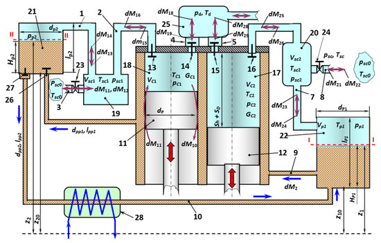
Figure 1.
Schematic diagram of a two-cylinder single-stage piston hybrid power machine with liquid movement due to vacuum suction.
The schematic diagram shows the main thermodynamic parameters in the cavities: pressure, temperature, volume and mass; mass flows of gas and liquid are indicated; the basic geometric dimensions necessary for the development of a mathematical model of work processes; basic schema elements; pistons, cavities, pipes, valves and control valves.
The schematic diagram of a two-cylinder single-stage reciprocating compressor in a pumpless version shown in Figure 1 works as follows. Piston 11 is supposed to be at the upper dead center (UDC), and piston 12, respectively, at the bottom dead center (BDC), the angle of camber is π. When piston 11 moves down, the gas in working cavity 18 expands to the suction pressure. After the pressure drops below the suction pressure, suction valve 13 opens and gas from cavity 19 flows through pipe 2 through valve 13 into working cavity 18.
The pressure in cavity 19 decreases and the gas from the atmosphere through pipe 3 through control valve 23 flows into cavity 19. In addition, gas through pipeline 1 also flows into cavity 19 from cavity 21. The pressure of the gas and the liquid decreases. Thus, at the angle of rotation φsc1 < φ ≤ π we observe a drop in pressure in cavity 21 (where φsc1 is the beginning of the suction process in cavity 19). At the same time, piston 12 moves from the BDC to the UDC.
The gas is compressed in working cavity 17 and discharged through discharge valve 15 into cavity 25, and then from there to the consumer.
Since suction valve 16 remains closed during gas compression and discharge, the pressure in cavities 20 and 22 remains constant and equal to the atmospheric value.
Thus, there is a pressure difference between cavities 22 and 21. Under the influence of this pressure drop, the liquid from cavity 22 enters the jacket of the compressor through pipe 9, and then, through non-return valve 26, into cavity 21.
With further rotation of the crankshaft from π to 2π, piston 11 of the BDC moves upwards, and in working cavity 18 compresses and discharges the gas through valve 14 and pipe 4 into cavity 25. When the pressure increases, valve 13 closes and the pressure in cavities 19 and 21 approaches atmospheric pressure. When piston 12 moves downwards from the BDC, the gas in cavity 17 expands to atmospheric and less. In this case, valve 16 opens and gas from cavity 20 flows into working cavity 17. The pressure drop in cavity 20 causes air to enter the atmosphere through pipe 8 and control valve 24, as well as from cavity 22 through pipe 7. The pressure in cavity 22 drops and the liquid, under the pressure drop, flows from cavity 21 through non-return valve 27 through pipe 10 to cavity 22. The coolant is heated in the jacket space and cooled in heat exchanger 28.
The coolant movement is affected by the height difference Δz = z2 − z1.
3. Materials and Methods
The following groups of elements can be distinguished in the conceptual diagram presented above (Figure 1):
- Cavities of alternating and constant volume without liquid (19, 18, 17, 25, 20);
- Cavities of constant volume, partially filled with fluid (21, 22);
- Gas pipes (1, 2, 3, 4, 5, 6, 7, 8), connecting cavities;
- Liquid pipes (9, 10).
We will conduct mathematical modeling of work processes in the abovementioned main elements of a piston single-stage two-cylinder compressor with a pumpless cooling system. When developing the motion of gas and liquid, we will use the principle of hierarchy, and mathematical models will be developed at two levels.
3.1. Mathematical Model of Compressor Section Work Processes
Currently, mathematical models are used when modeling the work processes of reciprocating compressors. They can be attributed to the symbolic mental models. The following types of mathematical models are used in the study of compressor work processes now: a mathematical model based on the polytropic approximation in compression and expansion processes, mathematical models with concentrated parameters and mathematical models with distributed parameters.
Taking into account that mathematical models with concentrated parameters are quite simple to implement and show good accuracy in determining thermodynamic parameters, we recommend their use.
The mathematical model is based on the following equations, written under the assumptions typical for these models [21]:
- Equation of conservation of energy in the form of the first law of thermodynamics of a body of variable mass;
- Equation of conservation of mass;
- Equation of change in the volume of the working cavity;
- Specific gas equation;
- Equation of dynamics of movement of the blocking element of a self-acting valve.
The determination of external heat transfer in the working cavities of the compressor section is carried out according to the Newton–Richman hypothesis. The elemental amount of heat discharged (supplied) from the compressed gas with temperature T of the surface of the walls of the working chamber during time dτ, can be determined as:
The average temperature of the walls of the surface of the working chamber, considering the function of temperature distribution on the surface of the walls, will be determined as:
After averaging on the surface, we obtain:
In general, the experiments carried out established that the temperature of the cylinder walls depends on the temperature of the intake gas, the initial temperature of the coolant, the degree of increase in pressure, the crankshaft speed, etc.
While studying the reciprocating two-cylinder compressor, the following experimental dependencies were obtained to determine the average surface temperature of the working chamber when using various coolants:
- water
- oil
- antifreeze
Coolant flow rate Qw should be substituted in ml/min in these equations.
It should be noted that the dependencies are obtained from the most significant factors: the degree of increase in pressure ε and the coolant flow rate Qw.
The heat transfer coefficient is a variable value at each point on the surface of the working cavity. When calculating, the surface-averaged values of the heat transfer coefficient are taken, its value is determined experimentally [21].
3.2. Mathematical Model of Fluid Flow in a Gas Pipe
The gas flow in connecting pipes is generally non-stationary, multidimensional, flowing with friction and heat exchange. Whereas a significant change in gas-dynamic parameters is observed only along the axis of the pipe. As a result, the problem of multidimensional gas flow is reduced to one-dimension (along the axis of the pipe).
A system of differential equations describing the non-stationary, one-dimensional flow of a compressible gas and including the equation of continuity, motion, conservation of energy and state will be written as [31,32]:
An analytical solution to the system of Equation (8) is impossible. As a result, we recommend solving it by one of the numerical methods.
One of the most effective numerical methods for solving the basic gas-dynamic equations is the large particles method [33].
Setting boundary conditions for the pipe connecting the two cavities is a complex physical task, its solution is presented in [34] etc. In accordance with [34]:
- for the left border, x = 0
If
If
- for the right border, x = lpp
If
If
And m is a number of breakdown nodes along the length of the pipe, n is current time increment.
The speed of sound is determined as:
In order to expedite the calculations, we simplify the calculations by assuming that:
- gas flow is isothermal and quasi-stationary;
- inertial forces are negligible.
After integrating the Bernoulli equation for gas and solving it with respect to the velocity of the gas leaving the pipe, we obtain:
It should be noted that the coefficient of friction along the length λpp is a function of the Reynolds number and therefore the velocity . Thus, Equation (18) must be solved by successive approximations.
Having determined we can easily determine the elemental mass, as .
3.3. Mathematical Model of Work Processes in a Constant Pressure Cavity Partially Filled with Liquid
The design scheme of the cavity is shown in Figure 2.
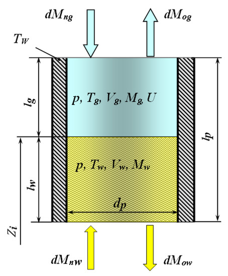
Figure 2.
Design scheme of a cavity of constant volume, partially filled with liquid.
The system of differential equations describing the change in the thermodynamic parameters of the gas will be written as:
The average value of the heat transfer coefficient is determined on the criterion equation [21], while the determining velocity will be determined as:
The heat exchange surface will be determined as .
The average temperature of the walls of the cavity will be determined as the average integrated value .
The system of equations describing the change in the thermodynamic parameters of the fluid will be written as:
Equation (21) is the first law of thermodynamics of a body of variable mass, written for an incompressible fluid.
Equation (21) is the equality of pressures at the gas–liquid phase interface.
The heat transfer coefficient can be determined from the criterion equation for laminar flow in pipes without taking into account natural convection [35]:
where Prw is the Prandtl number; Rew is the Reynolds number.
When calculating Rew the surface velocity of the liquid piston is the determining velocity.
It should be noted that during the operation of the hybrid machine, values and zp will change which should be taken into account when calculating the flow of liquid in pipes 9 and 10.
3.4. Mathematical Model of Fluid Flow in Connecting Pipes
The system of differential equations for describing the non-stationary one-dimensional flow of a viscous incompressible fluid will be written as a system of equations of motion and continuity [36,37,38]:
We recommend solving the recorded system by the method of characteristics.
The system of differential Equations (23) and (24), using a finite difference approximation, will be written as:
where is pipe wave resistance; is a coefficient that takes into account the hydraulic losses on the pipe segment; lpp is the total length of the pipe; N is the number of breakdown nodes by coordinate x; and is the liquid pressure in the pipe at the i-th node at time τ0 and τ0 +Δτ; , is the flow rate of the liquid at the i-th node of the pipe at time and .
The resulting system of algebraic equations is nonlinear (quadratic) with respect to and . As a result, it is recommended to solve it at each step in time and in each node by the method of successive approximations. The calculation is repeated until the relative absolute difference between the two approximations becomes an acceptable error.
The setting of boundary conditions on the left and right borders of the pipe was carried out based on the known values of the pressures on the left and right boundaries at each time.
Then, at :
Then, at :
At the second level of modeling, after integrating the Bernoulli equation into a quasi-stationary formulation written for liquid pipes, the following velocity values in the connecting pipe can be obtained:
The coefficient of friction in length is the function of the Reynolds number [39] and, accordingly, the velocity of the liquid in . As a result, Equation (31) is solved by the method of successive approximations.
The developed mathematical model of the working processes of the machine was developed and implemented in the FORTRAN programming environment for Windows. When developing the calculation program, the block-modular principle was used, as there were a lot of the same modeling objects.
It should be noted that when implementing the developed model, an iterative method was used, which is as follows. The calculation began with the angle of rotation in the left cylinder φl = π, and for the right cylinder the beginning of the calculation coincided with the upper dead point (UDP) φr = 2π = 0. At the beginning of the calculation, the values of thermodynamic parameters for the cavities, as well as the values of the initial levels of fluid in cavities 21 and 22 were set. After simulating the full cycle of the hybrid machine, the initial values of P and T and the final values are compared. Convergence is considered to be achieved if the discrepancy in the determination of pressure at the beginning and end of the cycle, in working cavity 18, in suction cavity 9 and in discharge cavity 25 was 300 Pa, and the temperature discrepancy in cavity 18 was 0.02 K.
It should be noted that, for comparison we can take the initial and final values of the levels of fluids in cavities 21 and 22, as well as the amount of fluid flowing per cycle from cavity 22 to cavity 21 in the forward direction through pipe 9 and in the opposite direction through pipe 10.
The implementation of the model, taking into account the calculation of non-stationary flows of gas and liquid in the connecting pipes, requires considerable time and does not have a significant impact on the integral parameters of the compressor, as a result, the priority was the calculation of the gas and liquid flow in the connecting pipes in the quasi-stationary setting.
The number of iterations in the simulation of the work cycle was limited: no more than 50. Iteration of differential equations was carried out in increments of 0.005° (number of breakdown nodes is 72,000). The increased number of breakdown nodes is due to computational instability in the calculation of cavities 21 and 22.
4. Experimental Studies
In order to gain new knowledge about the working processes of PHPMs (piston hybrid power machines) and validate the developed mathematical model of work processes, a PHPM prototype was developed in accordance with the patent [30] and a stand for its study was created.
4.1. Description of the Experimental Stand for Its Research
The PHPM prototype was created based on a serially produced piston compressor 130-3509009-11, which has the following main characteristics: compressor type-piston, oil; drive type-electric motor with belt transmission of torque to the crankshaft; number of cylinders-2; cylinder arrangement: in-line, vertical, with a stroke displacement of 180°; process pressure—(8–10) · 105 Pa; piston diameter—60 mm; piston stroke—38 mm; crankshaft speed—1100 rpm. The prototype is presented in Figure 3.
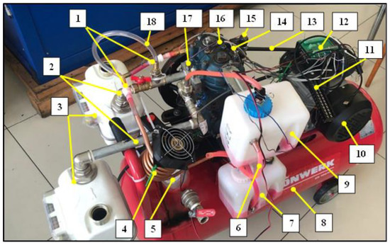
Figure 3.
General view of the experimental stand: 1—Check valves of the cooling system; 2—Suction lines; 3—Gas flow meters in the suction line; 4—Heat exchanger; 5—Flowmeter on discharge; 6—Pipe connecting the main and measuring tanks; 7—Main tank with coolant; 8—Receiver; 9—Measuring tank; 10—Electric motor; 11—Temperature sensor connection unit; 12—ADC; 13—Belt transmission; 14—Discharge line; 15—Temperature sensor; 16—Compressor; 17—Pressure sensor; 18—Pipe connecting the measuring tank to the suction line of the 2nd cylinder.
A schematic diagram of the machine is shown in Figure 4.
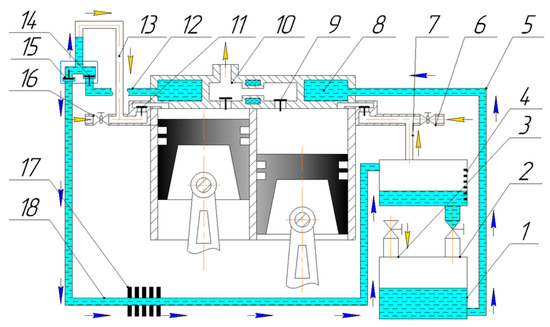
Figure 4.
Schematic diagram of the machine: 1—Tank with coolant; 2—Branch pipe with a valve connecting the measuring tank to the liquid container; 3—Branch pipe with a valve connecting the tank to the atmosphere; 4—Volume-calibrated scale of liquid level in a measuring container; 5—Coolant supply pipe; 6—Throttle gas suction line; 7—Pipe connecting the measuring tank to suction line 6; 8—Cooling jacket; 9—Pressure valve; 10—Gas discharge line; 11—Suction valve; 12—Pipe connecting the cooling jacket to the valve box; 13—Pipe connecting the measuring tank to the suction line of the first (left in the Figure) cylinder; 14—Suction valve; 15—Pressure valve; 16—Suction line with adjustable throttle; 17—Heat exchanger; 18—Coolant drain pipe.
During the experiments, the following parameters were measured: fluid and gas flow rate (pump and compressor section capacity); temperature of the cylinder walls, valve plate and coolant in the cooling system; gas pressure in the discharge line; instantaneous values of gas pressure in the working cavities of the compressor and in the suction lines; the crankshaft speed and the dead center moment.
In order to select instruments for recording these values, we analyzed instruments for measuring on the market. Instantaneous pressure measurement was carried out by a SMC Corporation-PSE 530-M5 PSE sensor. This sensor is compact, highly accurate and sufficient for the experiment measurement limits; the error of pressure measurement was about 1%. The flow rate of the liquid was carried out by measuring as one of the most reliable and accurate ways, the gas flow rate was measured by a membrane-type flow meter with a measurement error from 1.5% to 3%. Measurement of the temperature of the liquid and gas cylinder–piston group was carried out using temperature sensors-thermistors B57045-K 472-K, 4.7 kOhm; B57861-S 103-F40, 10 kOhm and B57869-S 302-F140, 3 kOhm. To measure the rotational speed, a constant magnetic field source was used, which was processed using the ZETLAB 230 ADC and the Oscilloscope program.
To conduct experimental research, a classical plan with fractional replication was developed [40]. During experiments, the compressor volumetric efficiency and the indicator isothermal efficiency were considered as the main operational functions.
4.2. Main Results of Experiments
The main objectives of experiments are: analysis of the influence of coolant flow on the temperature of parts of the cylinder–piston group, consumption and energy parameters.
Temperature of parts of the cylinder–piston group. The temperature of the parts of the cylinder–piston group is generally a function of the degree of pressure increase, the initial coolant temperature, the coolant flow rate, the ambient temperature, the angular velocity of rotation of the crankshaft, the type of compressible gas, etc.
Among this variety of factors that affect the temperature of the walls of the cylinder–piston group, we highlight the flow rate of coolant and the degree of pressure increase (discharge pressure at constant suction pressure) as the most significant independent parameters.
As the coolant flow rate increases, both the average valve plate temperature and the average cylinder wall temperature decrease (Figure 5 and Figure 6). Thus, with an increase in fluid flow from 0.2 L/min to 0.6 L/min, there is a decrease in the average temperature of the cylinder walls by (7–8) K at pd = 0.7 MPa, and a decrease in the average temperature of the valve plate by (10–12) K.
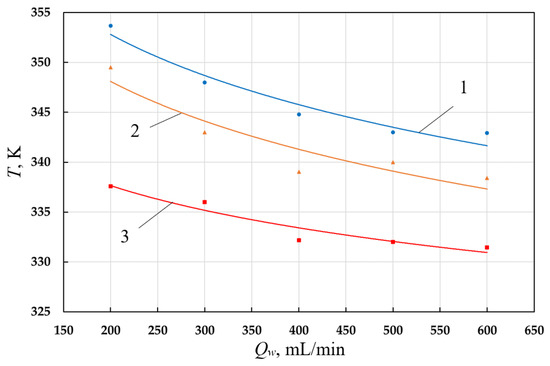
Figure 5.
Dependence of the valve plate temperature on the coolant flow rate (1—pd = 0.7 MPa; 2—pd = 0.5 MPa; 3—pd = 0.3 MPa).
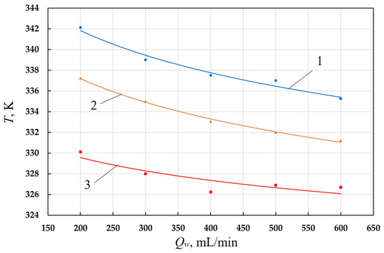
Figure 6.
Dependence of cylinder wall temperature on coolant flow (1—pd = 0.7 MPa; 2—pd = 0.5 MPa; 3—pd = 0.3 MPa).
In order to remove heat from the coolant, an air-cooled heat exchanger is installed on pipe 10, which reduces the temperature of the coolant by (30–40) K. Assuming that the temperature of the bottom of the piston is equal to the temperature of the cover, the temperature was averaged over the surface of the working chamber in accordance with [21].
Experimental studies of the operation of a two-cylinder hybrid power machine were carried out with various coolants: water, oil and antifreeze. The results of the studies carried out on the average temperature of the walls of the working chamber are processed and presented in the form of polynomials from the degree of increase in pressure ε and coolant flow Qw (Equations (5)–(7)).
Feed factor. The analysis of the effect of cooling on the components of the volumetric efficiency [21] established that cooling affected the volumetric efficiency: reducing the volume coefficient and increasing the temperature coefficient.
Using the results obtained, we conclude that in the range of coolant flow from 0.2 to 0.4 L/min there is an increase in the supply coefficient at higher discharge pressures (pd > 0.5 MPa). With a further increase in the coolant flow rate, there is a decrease in the supply coefficient by (10–12)%.
With an increase in the discharge pressure, in accordance with the theory of the work processes of reciprocating compressors, there is a decrease in the volumetric efficiency, which is primarily due to a decrease in the volume coefficient.
It should be noted that the intensity of the reduction in the volumetric efficiency does not depend on the coolant flow rate.
Thus, the experiments carried out made it possible to establish that the maximum value of the volumetric efficiency is observed in the range of coolant flow rates from 0.2 to 0.4 L/min.
Operation of the piston compressor cycle processes and indicator efficiency. To understand the physical nature of the effect of cooling on work supplied in the compressor and indicator efficiency, it is advisable to analyze the impact on the operation of each process in the cycle, using the resulting indicator diagrams at different coolant flows (see Figure 7).
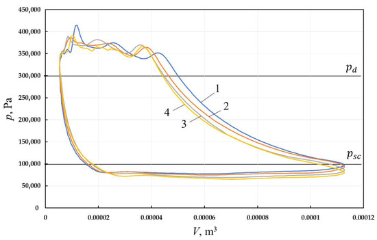
Figure 7.
Indicator diagrams of the working cavity of a two-cylinder single-stage piston power machine with fluid movement due to vacuum at gas suction, obtained at different coolant flows (1—coolant flow rate is 200 mL/min; 2—coolant flow rate is 300 mL/min; 3—coolant flow rate is 400 mL/min; 4—coolant flow rate is 500 mL/min).
The presented indicator diagrams show that with an increase in the flow rate of coolant, the amount of input work in the compression process decreases, the loss of work in the discharge process decreases, the technical work allocated during the expansion process increases, and the loss of work in the suction process associated with pumping the liquid increases. Figure 8 shows the dependence of the indicator isothermal efficiency of the compressor on coolant flow.
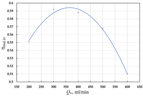
Figure 8.
Dependence of the indicator isothermal efficiency of the compressor on the coolant flow rate.
An increase in the indicator isothermal efficiency in the range from 6% to 8% is observed at a coolant flow rate of (0.3–0.4) L/min.
4.3. Validation of the Mathematical Model of Work Processes
The mathematical model of work processes was validated on a prototype with the following parameters (see Table 1).

Table 1.
Main parameters of the experimental sample.
In determining the length of liquid pipeline 9, an equivalent length of the section of the pipe equal to the jacket space in hydraulic resistance was determined. We established that at the coolant flow rate Qw = 0.8 L/min the hydraulic resistance of the jacket space is Δhw = 7×10⁻² m. Taking the laminar flow mode and the diameter of the pipe dpp9 = 0.008 m we obtain an equivalent length of 5.93 m. Taking into account the discharge and supply pipes, we assume that lpp9 = 6.0 m.
Length and diameter of pipe 10: a heat exchanger is installed on pipe 10 to cool the liquid coming from the jacket space. The heat exchanger was replaced by a section of the pipe with an equivalent length, which was determined by the previously described method. Taking into account the above, the length of the pipe is 6.5 m at dpp10 = 0.008 m.
The developed model of work processes, according to [21], is considered validated to a physical object if it describes its behavior qualitatively and quantitatively. The mathematical model of work processes was validated at different discharge pressures and coolant flows according to instantaneous and integral parameters.
As instantaneous parameters, we compare the indicator charts in the left and right cylinders with the indicator diagram obtained experimentally in the left cylinder.
The comparison showed that the greatest discrepancy in the determination of instantaneous pressure is observed at the beginning of the compression and at the end of the opposite expansion (10–15%). This is due to the delay in the recorded signal due to the connecting gas channel between the working cavity and the instantaneous pressure sensor.
We choose the main energy and consumption characteristics as integral parameters: the compressor volumetric efficiency and the indicator isothermal efficiency.
Table 2 presents comparisons of the main integral and consumption parameters of the machine under study at different gas discharge pressures.

Table 2.
Comparison of the main integral and consumption parameters of the machine under study at different gas discharge pressures.
The Table includes —volumetric efficiency of the left cylinder; —volumetric efficiency of the right cylinder; —average volumetric efficiency of the compressor section; —indicator isothermal efficiency of the left cylinder; —indicator isothermal efficiency of the right cylinder; —average indicator isothermal efficiency of compressor section; —indicator isothermal efficiency of the left cylinder, obtained experimentally; —indicator isothermal efficiency of the right cylinder, obtained experimentally.
From the results presented in the Table, we concluded that the average error in determining the volumetric efficiency and the total indicator isothermal efficiency is within (2–3)%, with the exception of the definition of the indicator isothermal efficiency at a discharge pressure 0.8 MPa.
Thus, the presented results allow us to conclude that the developed mathematical model validates the ongoing physical processes and can be used for parametric analysis.
5. Results of the Numerical Experiment and Discussion
We choose a two-cylinder single-stage reciprocating compressor as an object of research, the developed cooling system was implemented with it. Table 3, Table 4 and Table 5 show the main parameters of the reciprocating compressor and cooling system (see Figure 1):

Table 3.
Lengths and diameters of connecting gas pipes, and local resistances.

Table 4.
Lengths, diameters and local resistances of liquid pipes.

Table 5.
Compressor and cooling system parameters.
We select the main integral parameters of the compressor as functions, recorded for the left and right cylinders, the average values of thermodynamic parameters in the cavities and the coolant flow rate.
As a result of the analysis of the influence of operational and design parameters on the work processes of the machine under study, as well as taking into account the analysis of the working reciprocating compressors, the following operational and design independent parameters were selected, and the range of their change was determined:
- Discharge pressure pd at constant suction pressure is (0.4–0.8) MPa;
- Crankshaft speed is nrev = (800–1500) rpm.
Analysis of the effect of discharge pressure on work processes and integral parameters of the machine. With an increase in the discharge pressure, according to the general theory of compressor construction, the deviation of the compression process from the isothermal increases and the loss of work during the discharge process decreases, which causes the presence of an optimum in the indicator efficiency.
With an increase in pd the amount of heat removed during the compression process increases, which leads to a decrease in the polytrope ncmp (see Figure 9).
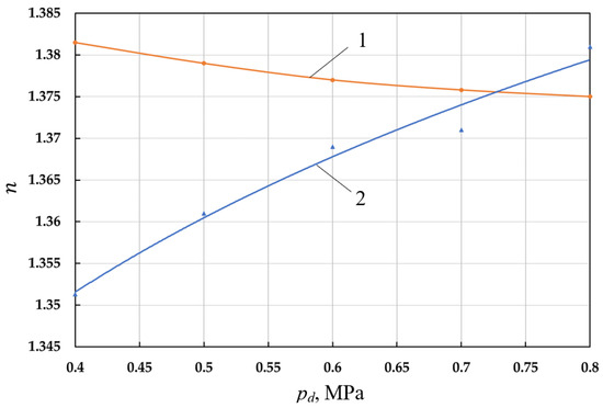
Figure 9.
Dependence of the polytrope index of the final parameters of the compression process (1—ncmp) and the polytrope index of the final expansion parameters (2—nexp) on the discharge pressure.
An increase in the amount of heat dissipated in the process of opposite expansion increases the opposite expansion polytrope nexp, resulting in a decrease in the returned work of the compression process and to a decrease in the indicator efficiency of the compression.
With an increase in pd the relative loss of work in the suction and discharge processes, the relative pressure losses in these processes decrease.
The relative pressure loss during the discharge process decreases slightly, while the discharge pressure doubles. This proves that the absolute values Δpd increase with increasing pd. Relative pressure losses during suction are increased. Since the suction pressure is constant, the decrease in relative losses allows us to suppose a decrease in the absolute values Δpsc. The decrease in Δpsc is due to a decrease in efficiency due to an increase in the process of opposite expansion and a decrease in the volume coefficient.
Increasing the loss of work in the processes of suction and discharge with an increase in Δpd does not compensate for the additional loss of work in the compression process from leaks and non-isothermal compression, as well as a decrease in the return work in the process of opposite expansion, results in a decrease in the indicator isothermal efficiency (Figure 10).
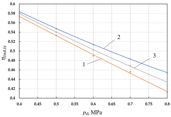
Figure 10.
Dependence of the indicator isothermal efficiency of the left (1—, right (2— cylinders and their average value (3— on the discharge pressure.
The decrease in the indicator isothermal efficiency is very significant and is 0.150 with an increase in pressure Δpd from 0.4 MPa to 0.8 MPa.
It should be noted that in this range of pressure changes, the maximum value of the indicator efficiency is not observed, and it is located in the area of lower values of pd. Usually, the maximum of the indicator isothermal efficiency is at equals 4.
With increasing pd there is an increase in pp1av and pp2av, and the difference between them decreases (see Figure 11).
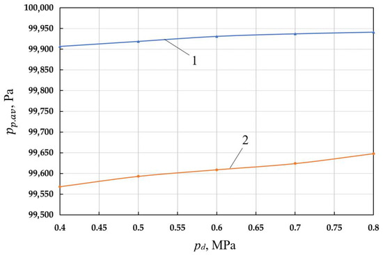
Figure 11.
Dependence of average pressures per cycle in cavities 21 (1—pp2.av) and 22 (2—pp1.av) on the discharge pressure.
Reducing the pressure difference in cavities 21 and 22 results in a reduction in coolant flow. The value Qw1 decreases from 285.3 L/min to 243.6 L/min, i.e., about (15–17)% (Figure 12).
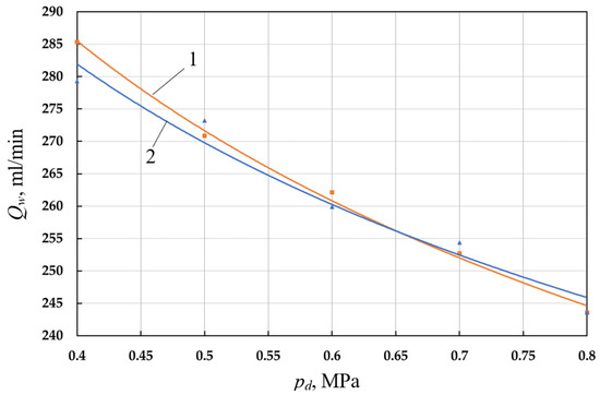
Figure 12.
Dependence of the volume flow rate of the coolant of the left (1—Qw1) and right (2—Qw2) cylinders on the discharge pressure.
The pressure in the suction cavity of the right cylinder is lower than the pressure in the suction cavity of the left cylinder. This causes the suction valve of the right cylinder to open earlier and the mass of the suction gas to be increased, and the values of pressure and work losses have a higher value. A higher value of the mass of the suction gas results in an increase in the relative loss of work and pressure in the right cylinder and to an increase in the indicator isothermal efficiency.
Analysis of the effect of the angular speed of rotation of the crankshaft on the work processes and integral parameters of the machine. With an increase in the crankshaft speed nrev the amount of heat removed decreases due to a decrease in the interaction time of the compressed gas with the surface of the working chamber. This results in the polytrope index of the final parameters increasing.
With an increase in nrev the value np, increases, resulting in a decrease in the technical work returned during the expansion process. It should be noted that the relative loss of work in the processes of suction and discharge begins to decrease with an increase in the number of revolutions higher than 1200 rpm. This is due to a decrease in the amount of suction gas with an increase in nrev.
Thus, all the conditions of the extremum of function are presented: indicator isothermal efficiency (see Figure 13). The extremum of the function is achieved at the crankshaft speed nrev = 1000 rpm and is 0.5403.
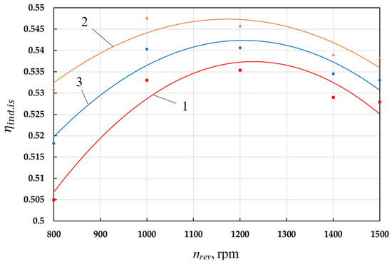
Figure 13.
Dependence of the indicator isothermal efficiency of the left (1—) and right (2—) cylinders and the average value (3—) on the crankshaft speed.
With an increase in the crankshaft speed, the value of the volumetric coefficient increases (np increases). At the same time, the leakage of the compressed gas decreases. The factors listed above result in the existence of an optimal value for the feed coefficient (see Figure 14). The optimal value of the feed coefficient is achieved in the same way as in the case of the indicator isothermal efficiency at nrev = 1000 rpm and is . When the number of revolutions increases to 1500 rpm, drops to 0.621.
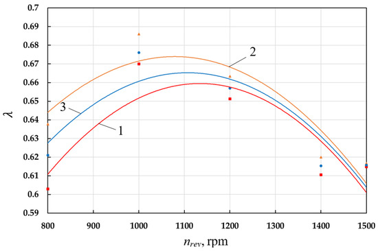
Figure 14.
Dependence of the supply coefficient of the left (1—) and right (2—) cylinders and the average value (3—) on the crankshaft speed.
With an increase in nrev the average pressure in cavities 21 and 22 decreases, which leads to an increase in the coolant flow rate (see Figure 15). The decrease in pressure in cavities 21 and 22 is due to an increase in hydraulic resistances, gas pipes with an increase in the speed of gas movement in them. With an increase in the flow rate of coolant with an increase in the number of revolutions, there is an increase in the level of liquid z1av and decrease in z2av. The flow rate of coolant with an increase in the number of revolutions from 800 rpm to 1500 rpm increases significantly, almost three times.
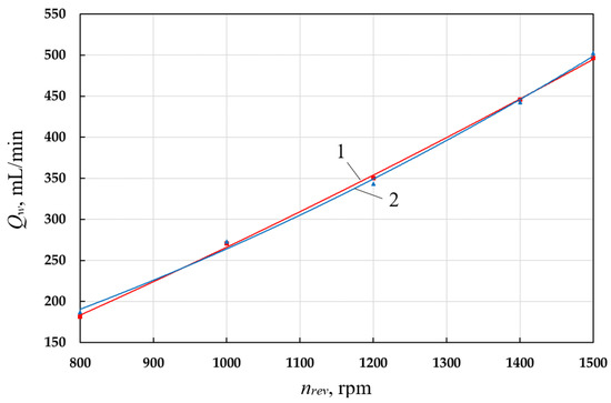
Figure 15.
Dependence of the volumetric flow rate of the coolant of the left (1—Qw1) and right (2—Qw2) cylinders on the crankshaft speed.
With an increase in the crankshaft speed, the pressure in the suction cavities of the left and right cylinders also decreases, which is due to an increase in hydraulic resistances.
6. Conclusions
A new schematic diagram of a pumpless liquid cooling system for a single-stage two-cylinder reciprocating compressor with liquid movement due to surface forces generated due to rarefaction in the suction cavities has been developed on the analysis of working processes and the existing shortcomings of the cooling systems of reciprocating compressors. Due to the effect of surface forces on the moving liquid, we increased the flow rate of the coolant, which leads to improvement in the cooling of the compressed gas and, as a result, to an increase in the indicator efficiency and feed rate.
A mathematical model of the working processes of a single-stage two-cylinder reciprocating compressor with the movement of a droplet liquid due to rarefaction at the gas suction has been developed based on the fundamental laws of conservation of energy and mass, as well as the equation of motion and state, including: calculation of thermodynamic parameters of gas in cavities of variable and constant volumes in the compressor section; calculation of gas flow in connecting pipelines; calculation of fluid flow in connecting pipelines; calculation of thermodynamic parameters of gas and coolant in constant volume cavities partially filled with liquid in the pump section.
Using a new schematic diagram, a prototype of a single-stage two-cylinder reciprocating compressor was developed with the movement of a coolant due to suction vacuum and experiments were carried out for a better understanding of the ongoing work processes in the cavities and pipelines of the machine and the validation of the developed mathematical model of work processes was performed.
A parametric analysis of the influence of the main operational (discharge pressure and crankshaft speed) parameters on the working processes and integral characteristics of the machine was carried out on the developed mathematical model to obtain the information necessary for the rational design and operation of this class of machines. Following the results, it was established:
- the coolant flow rate decreases with an increase in discharge pressure and increases with an increase in the crankshaft speed;
- in the range from 1000 to 1200 rpm, a maximum of indicator isothermal efficiency and compressor feed rate has been observed;
- maximum indicator isothermal efficiency and feed rate is observed at coolant flow rate in the range from 800 mL/min to 900 mL/min.
In accordance with the results of the research, the developed and studied pumpless liquid cooling system can be recommended for designing high-speed reciprocating compressors of low and medium pressure.
The developed and studied system cannot be used in single-stage single-cylinder reciprocating compressors due to its design features. It would be useful to increase the efficiency of this system in single-stage single-cylinder reciprocating compressors to use part of the compressed gas to organize a more intense movement of the liquid.
Author Contributions
Conceptualization, V.E.S.; methodology, V.E.S. and E.A.P.; software, E.A.P. and A.K.; validation, V.E.S., E.A.P. and A.K.; formal analysis, I.Y.B.; writing—original draft preparation, V.E.S. and E.A.P.; writing—review and editing, E.A.P.; visualization, A.K.; supervision, V.E.S.; project administration, V.E.S.; funding acquisition, V.E.S. All authors have read and agreed to the published version of the manuscript.
Funding
This research received no external funding.
Conflicts of Interest
The authors declare no conflict of interest.
Abbreviations
The nomenclature of the paper is shown below:
| specific isobaric heat capacity of a liquid, J/(kg*K); | |
| total internal energy, J; | |
| dp | diameter of a constant volume cavity partially filled with liquid, m; |
| dpp | inner diameter of the gas pipe, m; |
| elementary deformation work, J; | |
| elementary mass change, kg; | |
| elementary amount of fluid entering a constant-volume cavity partially filled with fluid, kg; | |
| i-th | inlet mass flow, kg; |
| i-th | outlet mass flow, kg; |
| elementary amount of fluid separated from a cavity of constant volume partially filled with fluid, kg; | |
| elementary amount of gas entering a constant-volume cavity partially filled with fluid, kg; | |
| elementary amount of gas separated from a constant volume cavity partially filled with fluid, kg; | |
| elementary external heat exchange between the compressed gas and the surface of the working chamber, J; | |
| elementary external heat transfer between the liquid and the walls of the cavity, J; | |
| heat exchange surface, m2; | |
| gas force acting on the valve plate, N; | |
| elastic force of the self-acting valve spring, N; | |
| force of friction when self-acting valve plate moving, N; | |
| side of the cylinder surface, m2; | |
| heat exchange surface of the valve body, m2; | |
| heat exchange surface of the piston head, m2; | |
| free surface area of a liquid in a constant-volume cavity partially filled with liquid, m2; | |
| the heat exchange surface in the gas part of the constant volume cavity partially filled with liquid, m2; | |
| side surface area of the constant volume cavity partially filled with liquid, m2; | |
| the area of the cover of the cavity partially filled with liquid, m2; | |
| self-acting valve weight force, N; | |
| acceleration of gravity, m/s2; | |
| the mass of gas in the working chamber of the left compressor, kg; | |
| the mass of gas in the working chamber of the right compressor, kg; | |
| current lift height of the valve, m; | |
| height of the liquid column in the cavity 22, m; | |
| height of the liquid column in the cavity 21, m; | |
| io | specific enthalpy of the detachable mass of the working fluid, H; |
| in | specific enthalpy of the attached mass of the working fluid, H; |
| specific enthalpies of the added gas masses, H; | |
| specific enthalpies of the separated gas masses, H; | |
| adiabatic exponent of a compressible gas; | |
| the height of the fluid in the cavity, m; | |
| lpp, | length of the gas pipe, m; |
| cavity height 21, m; | |
| lg | height of gas in a constant volume cavity partially filled with liquid, m; |
| M | mass of compressed gas, kg; |
| reduced mass of the valve plate, kg; | |
| mass of a gas in a constant-volume cavity partially filled with liquid, kg; | |
| number of local resistances in the connecting liquid pipe; | |
| number of in-flows; | |
| number of out-flows; | |
| P | pressure of compressed gas, Pa; |
| gas pressure in the working chamber of the left compressor, Pa; | |
| gas pressure in the working chamber of the right compressor, Pa; | |
| pressure in the cavity 25, Pa; | |
| pressure in a liquid at the gas–liquid interface, Pa; | |
| pressure in sections I-I, Pa; | |
| pressure in sections II-II, Pa; | |
| atmospheric pressure, Pa; | |
| pressure in the cavity 19, Pa; | |
| pressure in the cavity 20, Pa; | |
| P1 | pressure values in sections I-I, Pa; |
| P2 | pressure values in sections II-II, Pa; |
| current flow rate in the connecting pipe, m3/s. | |
| gas constant, J/(kg*K); | |
| T | temperature of compressed gas, K; |
| gas temperature in the working chamber of the left compressor, K; | |
| gas temperature in the working chamber of the right compressor, K; | |
| gas temperature in the cavity 25, K; | |
| temperature of a gas in a constant-volume cavity, K; | |
| gas temperature in the cavity 22, K; | |
| average temperature of working chamber walls surface, K; | |
| atmospheric gas temperature, K; | |
| gas temperature in the cavity 19, K; | |
| gas temperature in the cavity 20, K; | |
| function of cylinder surface temperature distribution; | |
| function of valve temperature distribution; | |
| function of the valve body temperature distribution; | |
| average temperature of the walls of the sides of the cavity partially filled with liquid, K; | |
| average temperature of the surface of the cover of the cavity partially filled with liquid, K; | |
| temperature of the fluid entering the cavity, K; | |
| ux | gas velocity along the pipe axis, m/s; |
| total internal energy of the compressible gas, J; | |
| V | volume of compressed gas, m3; |
| gas velocities in sections II-II, m/s; | |
| the current volume of the working chamber of the left compressor, m3; | |
| the current volume of the working chamber of the right compressor, m3; | |
| dead volume in the working cavity, m3; | |
| cylinder displacement, m3; | |
| volume of a gas in a constant-volume cavity, m3; | |
| fluid velocity in a constant volume cavity partially filled with fluid, m/s; | |
| the current volume of gas in the cavity 22, m3; | |
| velocity of the liquid in the connecting liquid pipe, m/s; | |
| cavity volume 19, m3; | |
| cavity volume 20, m3; | |
| geometric height in sections I-I, m; | |
| geometric height in sections II-II, m; | |
| geometric height of sections I-I in cavities 22, m; | |
| geometric height of sections II-II in cavities 21, m; | |
| angle of rotation of the crankshaft; | |
| Coriolis coefficients in selected sections I-I; | |
| Coriolis coefficients in selected sections II-II; | |
| heat transfer coefficient averaged over the surface of the working chamber, W/(m2*K); | |
| head losses along the length due to local resistances and inertial losses in cavities of constant volume, m; | |
| head losses along the length due to local resistances and inertial losses in cavities of constant volume, m; | |
| head loss along the length due to local resistances and inertial losses in the connecting liquid pipe, m; | |
| head loss along the length due to local resistances and inertial losses in the connecting liquid pipe, m; | |
| head loss along the length due to local resistances and inertial losses in the connecting liquid pipe, m; | |
| head loss along the length, m; | |
| loss of pressure on local resistance, m; | |
| Δx | elementary increment along pipe coordinate, m; |
| Δτ | elementary time interval, s; |
| ratio of piston stroke to twice the connecting rod length; | |
| λpp | friction ration along gas pipe; |
| values of local resistance coefficients at the inlet of the pipeline; | |
| values of local resistance coefficients at the outlet of the pipeline; | |
| i-th | local resistance in the connecting liquid pipe; |
| gas density, kg/m3; | |
| liquid density, kg/m3; | |
| τ | current time, s. |
References
- Kiliç, G.A.; Al, K.; Dağtekin, E.; Unver, U. Technical, economic and environmental investigation of grid-independent hybrid energy systems applicability: A case study. Energy Sources Part A Recovery Util. Environ. Eff. 2020, 1–16. [Google Scholar] [CrossRef]
- Unver, U.; Kara, O. Energy efficiency by determining the production process with the lowest energy consumption in a steel forging facility. J. Clean. Prod. 2019, 215, 1362–1370. [Google Scholar] [CrossRef]
- Talbott, E.M. Compressed Air Systems: A Guidebook on Energy and Cost; Savings Fairmont Press: Atlanta, GA, USA, 1993. [Google Scholar]
- Sapmaz, S.; Kaya, D. Investigation of energy efficiency and emission reduction opportunities in compressed air systems. Eng. Mach. 2017, 58, 23–36. [Google Scholar]
- Çağman, S.; Soylu, E.; Ünver, Ü. A research on the easy-to-use energy efficiency performance indicators for energy audit and energy monitoring of industrial compressed air systems. J. Clean. Prod. 2022, 365, 132698. [Google Scholar] [CrossRef]
- Pérez-Segarra, C.; Rigola, J.; Sòria, M.; Oliva, A. Detailed thermodynamic characterization of hermetic reciprocating compressors. Int. J. Refrig. 2005, 28, 579–593. [Google Scholar] [CrossRef]
- Pavlyuchenko, E.A. Analysis of the Primary Means for Increasing the Efficiency of Positive Displacement Compressors. Chem. Pet. Eng. 2022, 58, 309–314. [Google Scholar] [CrossRef]
- Diniz, M.C.; Melo, C.; Deschamps, C.J. Experimental performance assessment of a hermetic reciprocating compressor operating in a household refrigerator under on–off cycling conditions. Int. J. Refrig. 2018, 88, 587–598. [Google Scholar] [CrossRef]
- Posch, S.; Hopfgartner, J.; Dür, L.; Eichinger, M.; Stangl, S.; Almbauer, R. Thermal loss analysis of hermetic compressors using numerical simulation. Appl. Therm. Eng. 2018, 130, 1580–1589. [Google Scholar] [CrossRef]
- Santos, C.J.; Dutra, T.; Deschamps, C.J. Scrutinizing the sources of inefficiencies in the piston-cylinder clearance of an oil-free linear compressor. Int. J. Refrig. 2019, 104, 513–520. [Google Scholar] [CrossRef]
- Silva, L.R.; Deschamps, C.J. Modeling of gas leakage through compressor valves. Int. J. Refrig. 2015, 53, 195–205. [Google Scholar] [CrossRef]
- Rezende, G.C.; Silva, E.; Deschamps, C.J. Edge gap as a geometric parameter to characterize the sealing performance of compressor valves. Int. J. Refrig. 2018, 90, 257–263. [Google Scholar] [CrossRef]
- Zhao, B.; Xiaohan, J.; Shukai, S.; Wen, J.; Peng, X. FSI model of valve motion and pressure pulsation for investigating thermodynamic process and internal flow inside a reciprocating compressor. Appl. Therm. Eng. 2018, 131, 998–1007. [Google Scholar] [CrossRef]
- Ooi, K.T. Heat transfer study of a hermetic refrigeration compressor. Appl. Therm. Eng. 2003, 23, 1931–1945. [Google Scholar] [CrossRef]
- Oliveira, M.; Diniz, M.; Deschamps, C. Predicting the temperature distribution and suction gas superheating of an oil-free linear compressor. Proc. Inst. Mech. Eng. Part E J. Process Mech. Eng. 2017, 231, 47–56. [Google Scholar] [CrossRef]
- Tuhovcak, J.; Hejcik, J.; Jicha, M. Comparison of heat transfer models for reciprocating compressor. Appl. Therm. Eng. 2016, 103, 607–615. [Google Scholar] [CrossRef]
- Pont, A.; López, J.; Rigola, J.; Pérez-Segarra, C. Numerical dynamic analysis of reciprocating compressor mechanism. Parametric studies for optimization purposes. Tribol. Int. 2017, 105, 1–14. [Google Scholar] [CrossRef]
- Dutra, T.; Deschamps, C.J. A simulation approach for hermetic reciprocating compressors including electrical motor modeling. Int. J. Refrig. 2015, 59, 168–181. [Google Scholar] [CrossRef]
- Berman, Y.A.; Mankovsky, O.N.; Marr, Y.N.; Rafalovich, A.P. Cooling Systems for Compressor Units. L.; Mechanical Engineering, Leningrad Department: Leningrad, Russia, 1984; 228p. [Google Scholar]
- Frenkel, M.I. Piston Compressors. L.; Mechanical Engineering: Moscow, Russia, 1969; 744p. [Google Scholar]
- Plastinin, P.I. Reciprocating Compressors; Tom 1: Moscow, Russia, 2006; 456p. [Google Scholar]
- Van de Ven, J.; Li, P. Liquid piston gas compression. Appl. Energy 2009, 86, 2183–2191. [Google Scholar] [CrossRef]
- Qin, C.; Loth, E. Liquid piston compression efficiency with droplet heat transfer. Appl. Energy 2014, 114, 539–550. [Google Scholar] [CrossRef]
- Shcherba, V.E.; Bolshtyansky, A.P.; Lobov, I.E.; Grigoriev, A.V. Russian Federation, IPC F 04 B 39/06 (2006.01), Piston hybrid stage: No. 2015116962/06. Patent No. 2600212, 20 October 2016. [Google Scholar]
- Lobov, I.E.; Shcherba, V.E. Development and calculation of a liquid cooling system for a piston compressor using pressure fluctuations during gas discharge. Chem. Pet. Eng. 2016, 52, 251–259. [Google Scholar] [CrossRef]
- Lobov, I.; Shcherba, V.; Grigoriev, A. Analysis of the work processes in a piston hybrid power machine using fluctuations in gas pressure in the injection line. Omsk. Sci. Bull. 2016, 146, 40–44. [Google Scholar]
- Shcherba, V.E.; Bolshtyansky, A.P.; Kuzeeva (Trukhanova), D.A.; Nosov, E.Y.; Kaygorodov, S.Y. Russian Federation, IPC F 04 B 39/06, The Method of Operation of a Volumetric Machine and a Device for Its Implementation: No. 2015112262/06. Patent No. 2578776, 27 March 2016. [Google Scholar]
- Shcherba, V.; Kuzeeva (Trukhanova), D.A.; Nosov, E.Y. Mathematical modeling of working processes of a piston pump-compressor with a gas volume on suction. Vestn. Mashinostroeniya 2016, 4, 3–8. [Google Scholar]
- Shcherba, V.; Nosov, E.; Pavlyuchenko, E.; Kuzeeva, D.; Lobov, I. Analysis of the motion dynamics of liquid in a hybrid energy-converting piston machine with gas plenum in the intake. Chem. Pet. Eng. 2016, 52, 244–250. [Google Scholar] [CrossRef]
- Shcherba, V.E.; Ovsyannikov, A.Y.; Bolshtyansky, A.P.; Nosov, E.Y.; Tegzhanov, A.S. Russian Federation, IPC F04B 39/06 (2006.01), F04B 39/064 (2021/05), Two-Cylinder Reciprocating Compressor with Independent Liquid Cooling: No. 2020138070. Patent No. 2755967, 23 September 2021. [Google Scholar]
- Shcherba, V.E. Working Processes of Volumetric Compressors; M. Science: Moscow, Russia, 2008; 319p. [Google Scholar]
- Kotkas, L.; Zhurkin, N.; Donskoy, A.; Zharkovskij, A. Design and Mathematical Modeling of a Pneumatic Artificial Muscle-Actuated System for Industrial Manipulators. Machines 2022, 10, 885. [Google Scholar] [CrossRef]
- Belotserkovsky, O.M.; Davydov, Y.M. Method of Large Particles in Gas Dynamics; Main edition of physical and mathematical literature; M. Science: Moscow, Russia, 1982; 392p. [Google Scholar]
- Voronkov, S.S.; Prilutsky, M.K.; Fotin, B.S. Mathematical Model of a High-Speed Piston Two-Stage Compressor; Tr.VNIIKholodmash: Moscow, Russia, 1982; pp. 42–53. [Google Scholar]
- Isachenko, V.P.; Osipova, V.A.; Sukomel, A.S. Heat Transfer/Textbook for Universities, 3rd ed.; M. “Energy”: Moscow, Russia, 1975; 488p. [Google Scholar]
- Gimadiev, A.G.; Bystrov, N.D. Dynamics and Regulation of Hydraulic and Pneumatic Systems, Samara, Russia, 2010; 178p.
- Gavrilov, V.S.; Denisova, N.A. Method of Characteristics for One-Dimensional Wave Control, Nizhny Novgorod, Russia, 2014; 72p.
- Alam, M.K.; Bibi, K.; Khan, A.; Fernandez-Gamiz, U.; Noeiaghdam, S. The Effect of Variable Magnetic Field on Viscous Fluid between 3-D Rotatory Vertical Squeezing Plates: A Computational Investigation. Energies 2022, 15, 2473. [Google Scholar] [CrossRef]
- Basok, B.; Kremnev, V.; Pavlenko, A.; Timoshchenko, A. Aerodynamics and Complicated Heat Transfer with the Mixed Motion of Air in the Flat Duct of a High-Temperature Heat Exchanger. Energies 2022, 15, 865. [Google Scholar] [CrossRef]
- Shenk, H. Theory of Engineering Experiment; Mir M.: Moscow, Russia, 1972; 381p. [Google Scholar]
Disclaimer/Publisher’s Note: The statements, opinions and data contained in all publications are solely those of the individual author(s) and contributor(s) and not of MDPI and/or the editor(s). MDPI and/or the editor(s) disclaim responsibility for any injury to people or property resulting from any ideas, methods, instructions or products referred to in the content. |
© 2023 by the authors. Licensee MDPI, Basel, Switzerland. This article is an open access article distributed under the terms and conditions of the Creative Commons Attribution (CC BY) license (https://creativecommons.org/licenses/by/4.0/).