Article

A Virtual Impedance-Based Flying Start Considering Transient Characteristics for Permanent Magnet Synchronous Machine Drive Systems

1
Department of Electrical and Computer Engineering, College of Information and Communication Engineering, Sungkyunkwan University, Suwon 16419, Republic of Korea
2
Electric Propulsion Research Center, Korea Electrotechnology Research Institute (KERI), Changwon 51541, Republic of Korea
3
Dawonsys Co., Ltd., Anyang 15655, Republic of Korea
*
Author to whom correspondence should be addressed.
Energies 2023, 16(3), 1172; https://doi.org/10.3390/en16031172
Submission received: 6 January 2023 / Revised: 17 January 2023 / Accepted: 19 January 2023 / Published: 20 January 2023
(This article belongs to the Special Issue Control Technologies for Permanent Magnet Motor)

Abstract

:
A virtual impedance-based flying start considering transient characteristics for permanent magnet synchronous machine drive systems is proposed. The conventional flying start based on virtual resistance (VR) assumes that the load of the system is resistive. However, the maximum value of VR, which is determined by the machine parameter and sampling frequency, is sometimes small. In this case, the load of the system is non-resistive. This assumption error causes an estimated position error and degrades transient characteristics. In the proposed method, algebraic-type virtual inductance (VI) is added to the estimation current regulator of the flying start based on VR. This change improves the accuracy of the estimated rotor position and the transient characteristics. In addition, the discrete-time system model of the proposed flying start method is given, the stability was analyzed considering the change in VR caused by the proposed method, and the improvements were verified by PSIM simulations and experimental results.

1. Introduction

Permanent magnet synchronous machines (PMSMs) have been used in industrial applications owing to such advantages as higher power density, higher torque density, and higher efficiency [1,2,3,4,5,6,7,8]. Field-oriented control (FOC) has been widely used for high-performance control of PMSMs. In FOC, the position of the rotor flux is necessary and obtained with position sensors, such as encoders or resolvers [9,10,11,12]. However, using position sensors results in hardware complexity, increased cost, low reliability, and increased noise. Therefore, sensorless control methods have been studied during the past few decades [13,14,15].
The back electromotive force (EMF) induced by the rotation of a machine is completely canceled by feed-forward compensation in the sensor inverter using position and speed information [16]. However, the position and speed information cannot be known prior to the start of pulse width modulation (PWM), as the sensorless controlled PMSM drive system uses electrical responses to estimate position and speed from the observer. In this case, beginning FOC without position and speed information means incomplete canceling of the back EMF, which causes a large inrush current. Because the transient state caused by the inrush current cannot be predicted and there is a risk of inverter destruction, appropriate control methods are needed to estimate position and speed. Therefore, the initial position/speed estimation method, which is called “flying start”, of a rotating machine before FOC has been studied recently [17,18,19,20,21,22,23,24,25,26,27,28].
One method is to measure the voltage at the rotating stator terminals [17,18]. Position and speed can be determined by measuring the back EMF induced by the rotation of the machine; however, additional voltage sensors are required for this method. This leads to reliability and cost issues.
Another approach is the high-frequency (HF) signal injection method [19,20,21,22,23]. In this approach, the HF component is injected to estimate the position. This method can detect the position not only in a low-speed range but also at zero speed; however, its performance depends on the magnetic saliency or geometry of the rotor, and the range of application is limited. Furthermore, an additional demodulation procedure and an observer or state filter are required to estimate position, so it is difficult to implement.
In the zero-voltage injection method [24,25,26] for the flying start, the inverter intentionally injects several zero-voltage pulses causing short circuits and changing the current. The speed and position of the machine are estimated based on the current reaction. The disadvantage of this method is its high dependency on machine parameters.
To avoid parameter dependency, a repeated zero-voltage vector injection method has been proposed [20]. In this method, all the top insulated-gate bipolar transistors (IGBTs) of the inverter are turned off, while the bottom IGBTs operate with a very short duty cycle. The method that uses current spikes induced by a short duty cycle is relatively robust to motor speed changes and parameter variations. However, a proper duty cycle controller requires a long convergence time depending on the duty cycle rate and the design of the dead zone; therefore, the return to sensorless control is delayed and difficult to apply in applications requiring high reliability.
Recently, a novel flying start approach based on virtual resistance (VR) was proposed [28]. In this method, the initial value of the inner VR is set to a high value, and the inrush current is regulated because it is implemented in the control loop. Through the use of the estimation current regulator, the VR is adjusted to obtain a current of the desired magnitude. Compared with other flying start methods, this method can be applied without being affected by parameters, and position estimation is possible without burdening the mechanical system.
The conventional flying start based on VR [28] assumes that the load of the system is highly resistive by a relatively higher value of VR than stator impedance. Therefore, the position of the rotor can be determined using the phase-locked loop (PLL) of the current. However, the discrete stable range of VR is parameter dependent, and some applications have a low maximum value of VR. Therefore, when this assumption is applied to other applications, the error caused by the stator inductance cannot be neglected in the speed estimation system.
In this article, a flying start method based on virtual impedance for PMSM drives considering the transient characteristics is proposed to eliminate the estimation error caused by neglecting the stator inductance in position estimation. The VR is adjusted by the conventional method [28]. Additionally, virtual inductance (VI) is implemented based on algebraic approximation, and a VI controller is added to the conventional estimation current regulator. This controller adds negative inductance to the system, making the load of the system completely resistive. Therefore, the proposed method estimates the position of the rotor more accurately and improves the transient characteristics when making the transition.
The remainder of this article is organized as follows. In Section 2, the conventional flying start method based on VR and its assumption error are reviewed. In Section 3, the algebraic type of VI, implementation of VI, modified estimation current regulator, and the discrete-time system model of the proposed method are described. The simulation results, showing the decreased position estimation error and the discrete-time stability analysis of the proposed method, are given in Section 4. The proposed method was experimentally verified on interior PMSM (IPMSM), as described in Section 5. Finally, Section 6 presents the conclusions of this study.

2. Review of Conventional Flying Start Based on VR

2.1. Concept and Implementaion of VR

When the PWM starts in a sensorless PMSM drive system, the back EMF is not completely canceled out because the rotation position and speed are undetermined. In this case, the incomplete cancelation causes the inrush current in the flying start. Therefore, suppressing excessive inrush current is a major task in a flying start. In this method, the limited inrush current is obtained by setting the initial value of the VR high. The regulated current is used to estimate the rotor position and speed by PLL.
The PMSM side is equivalent to the back EMF Ek (k = a, b, and c) and the stator inductance Ls, and stator resistance Rs. The machine parameters assume that the phase inductances are identical. An inverter side can be expressed as a variable resistance Rv. An equivalent circuit with VR can be expressed as:
E k = R s + R v i k + L s d i k d t   k = a , b , c .
When Rv is much greater than Rs and Ls, Rs and Ls are negligible. Therefore, (1) can be approximated as:
E k R v i k .

2.2. Design of the Position/Speed Estimator

The estimated back EMF can be expressed as using the actual back EMF:
E γ E δ = cos θ ˜ sin θ ˜ sin θ ˜ cos θ ˜ E d E q E q sin θ ˜ E q cos θ ˜
where E γ and E δ are the γ-δ axes of the estimated reference frame, E d and E q are the d-q axes of the actual synchronous reference frame, and θ ˜ is the position error between the estimated and actual angles. In this case, E d is negligible.
Because the stator impedance is resistive owing to the high VR, the γ-δ axes’ estimated current can be expressed by dividing (3) by the VR. Since the stator resistance component is extremely small, it can be neglected. The estimated γ-axis current i γ can be expressed as:
i γ = i d cos θ ˜ + i q sin θ ˜ i q sin θ ˜ s i g n [ i q ] I s sin θ ˜
where i d and i q are the d-q axis currents of the actual synchronous reference frame, I s is the magnitude of the stator current, and s i g n is the signum function that outputs 1 or −1.
In the steady state, using the estimation current reference I e s t * , the position error can be expressed as:
s i g n [ i q ] i γ I e s t * sin θ ˜ θ ˜ .
Using (5) as the input and basic structure of a PLL, the position and speed estimator is implemented. In (5), sign[iq] can be replaced with sign[Eq] and sign[ ω r ] because they are the same under a load made resistive by VR.
Figure 1 shows the structure of the position and speed estimation system. Figure 1a is the actual block diagram of the estimator using (5). The actual estimator in this study was implemented to be the same as the basic structure of the PLL by linearization. The output of the proportional–integral (PI) controller with θ ˜ as input is the estimated speed ω ^ r . Assuming that this value is constant, the estimated position θ ^ r can be obtained as a ramp function by adding an integrator to the actual estimator.
Figure 1b shows the equivalent block diagram of the actual estimator. The open-loop and closed-loop transfer functions can be expressed as:
G o , p l l s = k p , p l l s + k i , p l l s 2
G c , p l l s = G o , p l l 1 + G o , p l l = k p , p l l s + k i , p l l s 2 + k p , p l l s + k i , p l l
In (6) and (7), kp,pll and ki,pll are proportional and integral gains of the PLL. Because (7) is a transfer function of the second-order low-pass filter, estimation performance can be designed by determining the PI gains. Depending on the damping ratio ζ and natural frequency ω n , the PI gains can be determined as:
k p , p l l = 2 ζ ω n k i , p l l = ω n 2 .
In this study, the ζ was set to 0.707 to obtain a stable response. The natural frequency was unified and the effect of eliminating the position error of the proposed method was compared in Section 4 and Section 5.

2.3. The Range of VR Considering the Stability and Estimation Control System

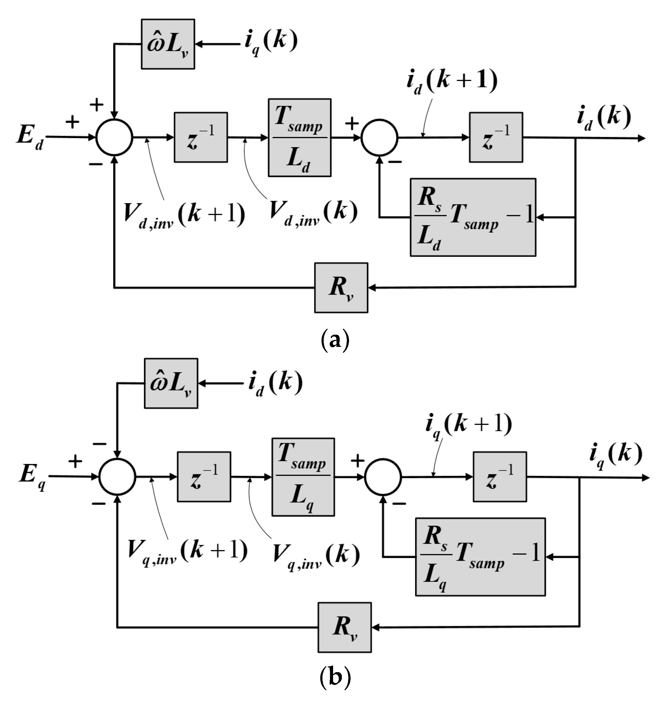
In this approach, the higher the VR, the smaller the inrush current. However, if the VR is too high, it causes instability in the electrical system. Conversely, a low VR causes an inrush current, and the range should be defined based on stability analysis. In this study, the range of VR is set based on the discrete-time stability analysis of Ref. [28]. Figure 2 shows the d-q axis block diagram of the VR implementation based on the discrete inverter model [29]. Because the back EMF is a function of speed, it can be considered almost constant relative to the electrical system. Therefore, Figure 2a can be modified as Figure 2b. The transfer function of the simplified model is calculated as:
T ( z ) = 1 R s ( 1 e R s L s T s a m p ) z 2 e R s L s T s a m p z + R v R s ( 1 e R s L s T s a m p )
where Tsamp is the sampling period. The stable range for VR can be defined using the characteristic of Equation (9). Assume that in the short sampling period, the stable range of the VR can be simplified as:
0 < R v < η L s T s a m p R s .
The machine parameter varies according to the stator current, temperature, etc. Therefore, η has a value between 0 and 1 as a margin for parameter variation.

2.4. Assumption Error of the Conventional Flying Start Based on VR

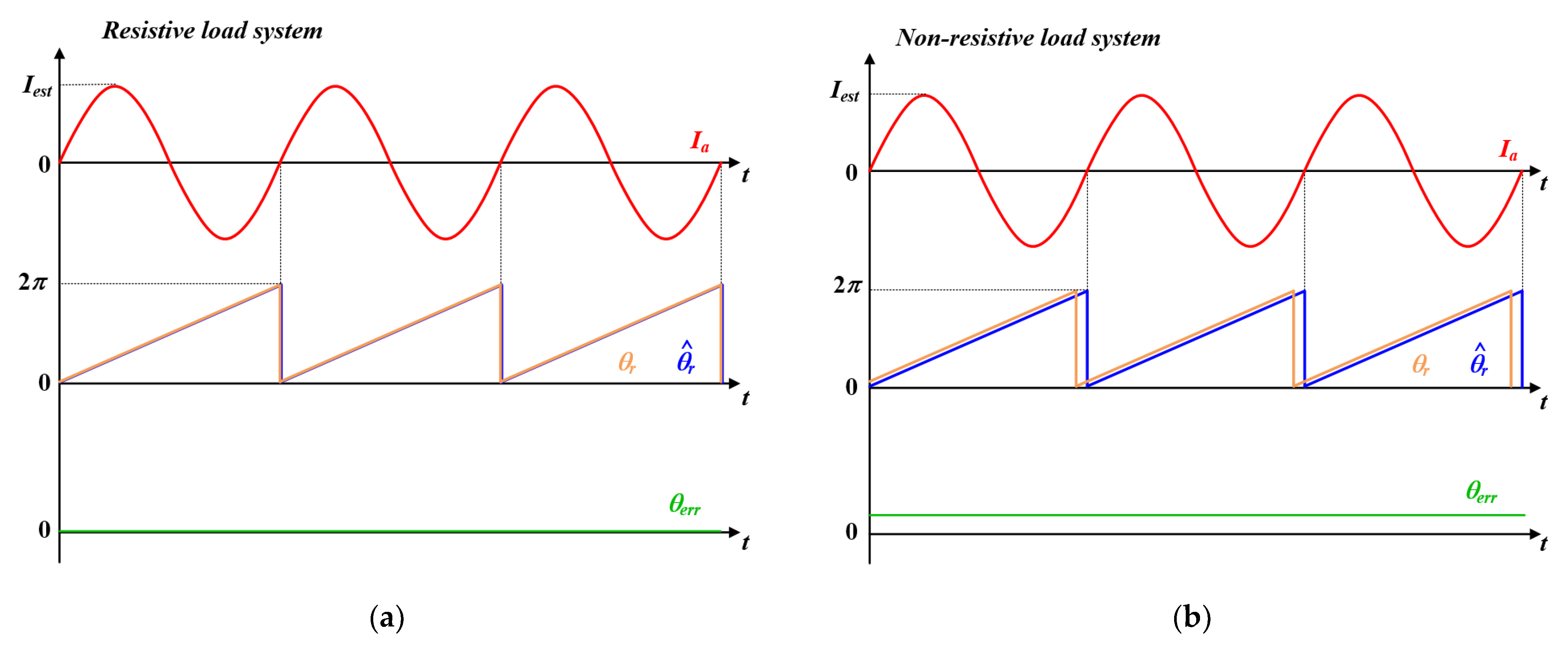
In a previous study [28], the load of the system was considered resistive. The rotor position is estimated by PLL using stator current. However, as shown in (10), when the sampling frequency is low or the stator inductance is small, the maximum value of the VR in the stable region decreases. In these cases, the VR may not be sufficient to neglect the stator inductance. Therefore, the load of the system is non-resistive. In the case that Rv is not sufficiently greater than Rs and Ls, the Rs and Ls are not negligible and the error between the actual rotor position and estimated rotor position increases. Figure 3 shows the waveforms of resistive and non-resistive load systems, showing the errors of the conventional assumptions.

3. Proposed Flying Start Method Based on Virtual Impedance

The proposed flying start method based on virtual impedance is described in this section. The implementation of virtual impedance, the proposed estimation regulator with virtual impedance, the discrete-time system model implementing the proposed method for stability analysis, and the control block diagram of the proposed method are described.

3.1. Implementation of Virtual Impedance

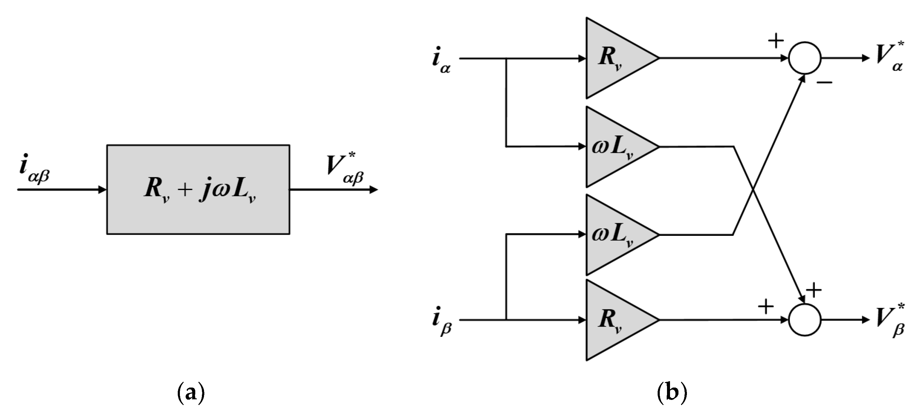
Figure 4 shows the general form of implementation of the virtual impedance. There are two types of virtual impedance: implemented in the outer loop and inner loop. The inner virtual impedance has a faster response than the outer VR and does not need position information. However, the outer virtual impedance method requires the speed and position of the machine. Therefore, the inner virtual impedance is more suitable for a sensorless system. The virtual impedance transfer function can be expressed as follows:
G v ( s ) = R v + s L v .
Using (11), the virtual impedance can be modified and implemented for various purposes. As shown in (11), derivative control is involved in realizing the VI. However, owing to its disadvantage, such as noise sensitivity, it is rarely used in practice. Several alternatives have been reported instead of using derivative control.
A representative alternative is an algebraic type depicted in Figure 5. This type replaces the derivative term s with j ω and it is easy to implement for a three-phase system, such as a grid-tied inverter and a motor drive [30,31,32]. The phase shift resulting from the inductance can be easily obtained using the cross-coupling feedback of the current vector, and ω   used for cross-coupling feedback can be obtained from the position/speed estimator.

3.2. Proposed Estimation Current Regulator with Virtual Impedance

Figure 6 shows a control block diagram of the VI controller. The VR is adjusted to regulate the magnitude of the stator current Is. The VR controller is implemented in the same manner as in a previous study [28].
To make the load of the system resistive, the VI controller uses a negative inductance equal to the d-axis stator inductance as a reference value. When the estimation current regulator for the VI is designed as (12), the total transfer function of the VI controller can be expressed as a first-order low-pass filter:
C e c , L ( s ) = ω e c , L
The bandwidth of the virtual impedance controller can be designed by adjusting Cec,R (s) or Cec,L (s), but it can affect the stability of the control system, which is maintained at less than one-tenth of the electrical bandwidth of the actual R-L load. In the proposed estimation current control system, the decrease in the VI increases the VR. If the VI regulator is designed with excessively high bandwidth, the VR may exceed the stable region boundary. Therefore, the bandwidth of the VI is designed to be less than one-fifth of the VR bandwidth.

3.3. Discrete-Time System Model of the Proposed Flying Start

The state vector is selected x k = V d , i n v k   V q , i n v k   i d k   i q k T , where V d , i n v k and V q , i n v k are the kth d, q axis inverter output voltage, and i d k and i q k are the kth d, q axis current. Figure 7 shows the d, q axis system block diagrams of the proposed flying start based on the discrete inverter model [29]. Based on Figure 7, the discrete-time state-space model can be expressed as:
x k + 1 = A x k + u k
where system matrices are defined as:
A = 0 0 R v ω L v 0 0 ω L v R v T s a m p L d 0 0 T s a m p L q a 33 0 0 a 44 ,   a 33 = R s L d T s a m p 1 ,     a 44 = R s L q T s a m p 1 , u k = E d k     E q k     0     0 T .

3.4. Implementation of the Virtual Impedance-Based Flying Start Method

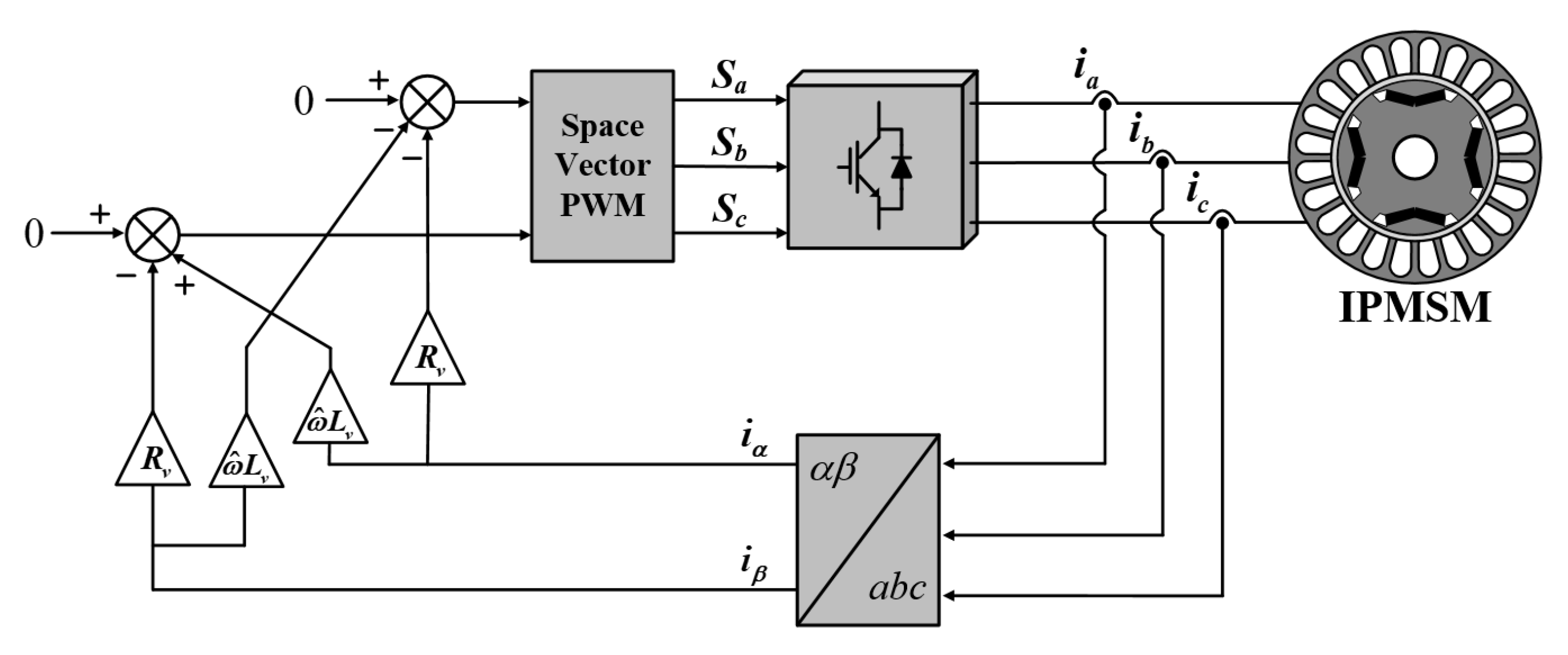
The implementation of the proposed virtual impedance method is shown in Figure 8. The VR and VI are determined, as shown in [28] and Figure 6, respectively.
For the flying start, the initial value of the VR that suppresses the inrush current uses the maximum value in the stable region. In addition, to estimate the position of the rotating rotor more accurately, the estimated position is compensated for using the VI. When the position estimation is completed through the proposed method, sensorless torque control is performed. In this study, a sensorless method based on the extended EMF model was used [34].

4. Simulation Results

In this section, the discrete-time stability was analyzed, and the proposed virtual impedance-based flying start method was simulated using Powersim software (PSIM version 9.1). Table 1 shows the parameters of the IPMSM drive system used in the simulation. The bandwidths of the position/speed estimator and estimation current regulator were determined in Section 2 and Section 3.
In the proposed flying start method, the VR value is affected by VI. Therefore, in the discrete-time stability analysis in this article, the VR was approximated to a quadratic equation related to the VI. The data used for approximation are obtained through simulation. The approximate quadratic equation is:
R v = 162 , 500 L v 2 757.5 L v + 1.283
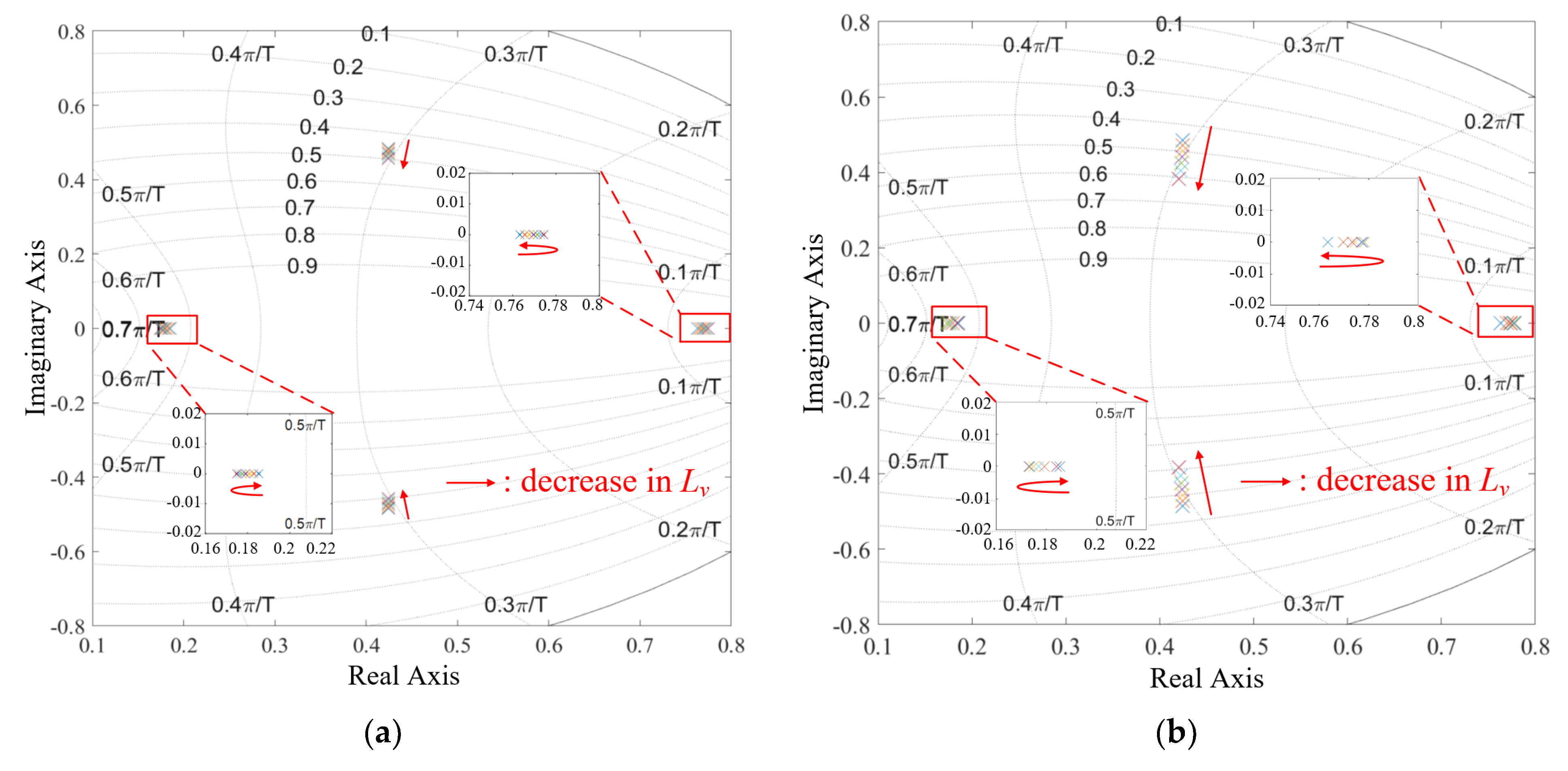
Figure 9 shows the pole loci of the proposed method with different virtual impedance. The discrete-time stability was analyzed at 1000 rpm and 3000 rpm. The VI used for the analysis changed from 0 to −Ld. As shown in the analysis results, within the defined VI range, the poles are always located in the stable region. Additionally, because the VI is always fed back by multiplying the speed term, the pole trajectory is always shared and even the rotor speed changes. The higher the rotor speed, the greater the variation of the pole on the complex plane according to unit VI.
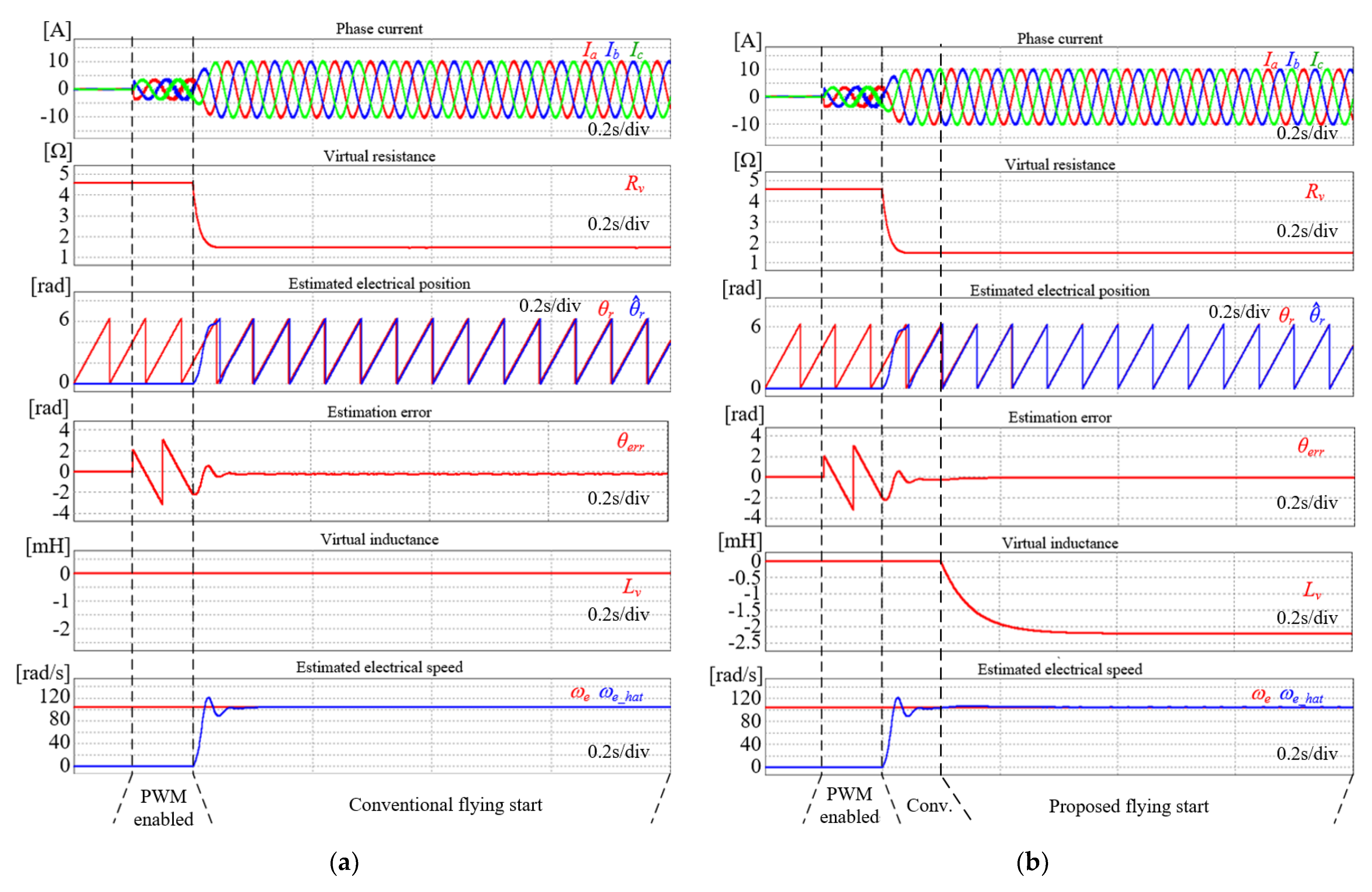
Figure 10 shows the simulation results at 500 rpm. The conventional flying start method and the proposed flying start method, which adds VI, are compared. The I e s t * is set to 10 A, and the maximum value in the stable region of VR is 4.6 Ω. After PWM begins, from 0.1 s to 0.2 s, the stator current is regulated by a pre-set maximum value of VR; therefore, the inrush current can be suppressed. During the flying start, the VR is adjusted appropriately by the estimation current regulator such that the stator current converges to the estimation current reference. Simultaneously, the position and speed of the rotor are estimated.
Position estimation error by assumption error of the conventional method θ e r r   is defined as:
θ e r r = θ r θ ^ r
where θ r is the actual rotor position and θ ^ r is the estimated rotor position. In the conventional method, θ e r r exists in the steady state, as shown in Figure 10a. This estimation error originated from the assumption error of the conventional method.
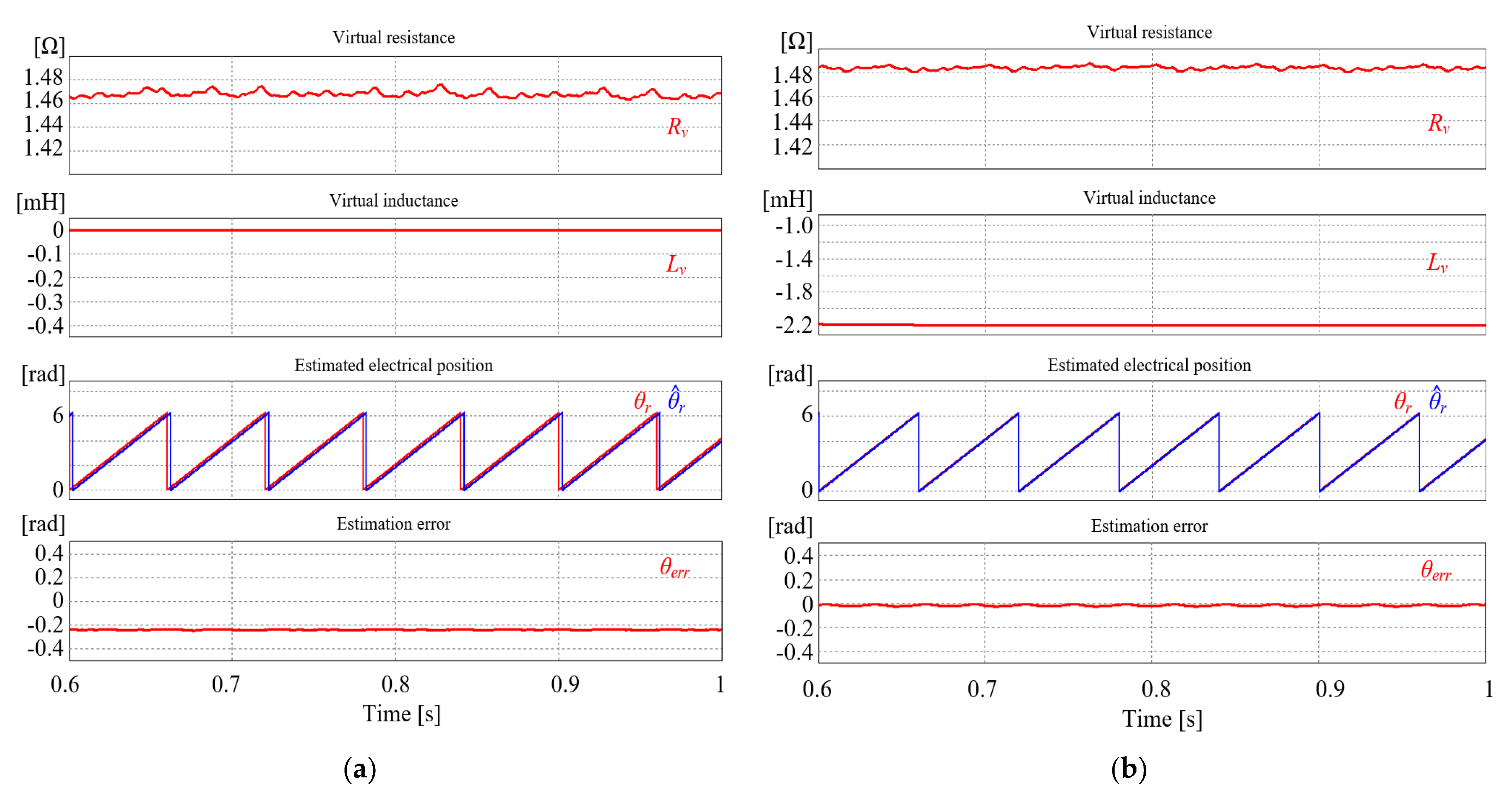
A magnified comparison of Figure 10 is presented in Figure 11. When the I e s t * is set to 10 A, the VR converges to about 1.465 Ω in the conventional method. By contrast, the VR converges to about 1.483 Ω in the proposed method. As the VI increases in the negative direction, the VR increases slightly. In the conventional method, a decrease in the VR causes an increase in the stator current. However, a phase shift appears instead of a decrease in the stator current because the VI is added to the estimation current regulator in the proposed method. Due to the addition of the VI, the θ e r r can be reduced close to zero.
Figure 12 shows a comparison of the transient characteristics of non-flying start, conventional, and proposed methods during the mode transition. In the transition to sensorless control, the reference current is set to zero. In the case without flying start, a transient current higher than the rated current occurs and θ ˜ , the input of the position estimator, is also very large.
In the case of the conventional method, the peak currents are 2.9 A (Ia_peak), 2.8 A (Ib_peak), and 1.7 A (Ic_peak) after mode transition. However, they are 1.9 A (Ia_peak), 2.1 A (Ib_peak), and 1.3 A (Ic_peak) in the proposed method. In the conventional method, the peaks of all stator currents are greater than those of the proposed flying start method in the transient state.
In comparison, under the same position estimator bandwidth, the peak value of θ ˜ is 0.47 rad for the conventional flying start method, whereas it is 0.2 rad for the proposed method.

5. Experimental Results

To verify the transient characteristic improvement of the proposed flying start method, experiments were conducted using an IPMSM test bench. The configuration of the IPMSM test bench is illustrated in Figure 13. The proposed flying start method was implemented using the TMS320F28335 DSP board. The I e s t * is set to 10 A and the switching frequency was set to 2 kHz for a low value of maximum VR. The PI current controller was disabled and output zero values in the flying start procedure. However, in the sensorless control, the PI current controllers were abled. The reference voltage vectors were the products of current and VR or the output of the PI controller, respectively. The load motor was operated in speed mode to imitate the flying start condition and the IPMSM was operated in flying start mode and sensorless torque control mode. The experiments were conducted at 500 rpm and 1000 rpm.
Figure 14 and Figure 15 show the experimental results of the conventional flying start method at 500 rpm and 1000 rpm. These figures show the general waveforms of the VR-based flying start method, which includes the inrush current suppression and estimation current regulation. The phase current is adjusted using an estimation current regulator that output the VR. The position of the rotor is estimated by θ ˜ r   derived by (4). The VR is 1.13 Ω and 2.42 Ω at 500 rpm and 1000 rpm, respectively, in a steady state for the conventional method.
However, after starting the estimation current regulator, θ e r r is 0.23 rad (7.3% of maximum position error) in the steady state for position estimation because of the assumption error.
Similarly, for an accurate comparison, the magnified experimental result of the conventional method is shown in Figure 16. Because the θ ˜ r in (4) is derived from resistive load assumption, there is an estimated position error owing to the effect of ignored stator inductance.
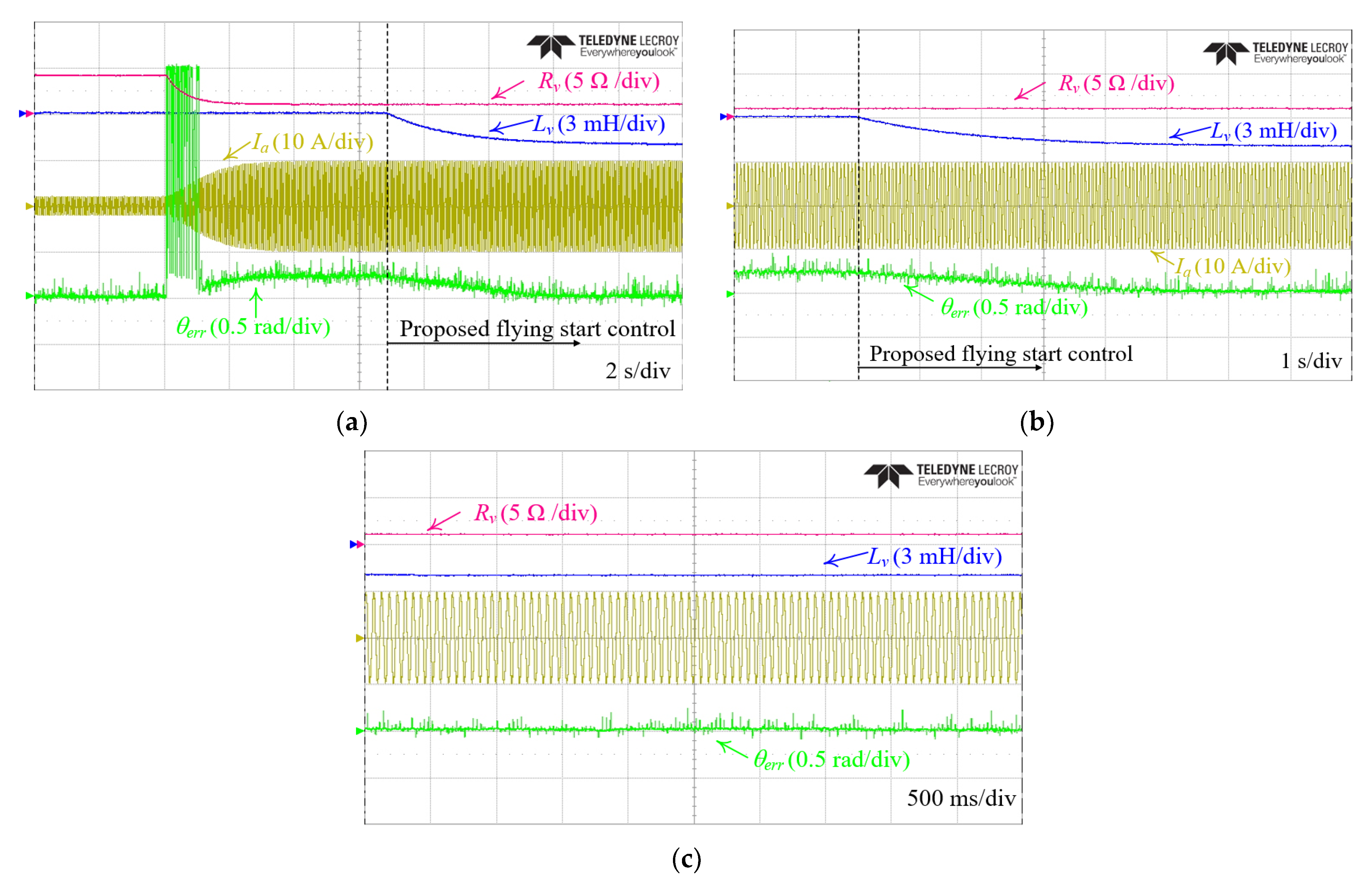
Figure 17 shows the experimental results of the proposed virtual impedance-based flying start at 500 rpm. To eliminate the position estimation error, VI is applied. As the VI approaches the steady state, the θ e r r gradually approaches zero. The θ e r r is 1.5% of the maximum steady state position error of the proposed flying start method, 0.05 rad, and the position estimating the accuracy of the proposed method is improved compared to the conventional method.
Figure 18 shows the validity of the proposed flying start method for another speed range. Similar to Figure 17, Figure 18 shows Rv, Lv, a-phase current, and θ e r r . As in the conventional method, the estimation current is controlled at 10 A. The VR controller and the VI controller use I s * and −Ld as a reference, respectively, and the VI controller is not affected by the VR controller. However, the VR controller is affected by the VI. Therefore, in the proposed flying start method, the VR is slightly increased to 1.15 Ω and 2.43 Ω at 500 rpm and 1000 rpm in the steady state. The θ e r r is 0.9% of the maximum position error in the steady state of the proposed flying start method, 0.03 rad, and the position estimating accuracy is improved.
Figure 19 shows the magnified experimental results of the proposed flying start method with the actual position and estimated position. It is proved that the proposed flying start method can estimate the position more accurately than the conventional method. In both speed ranges, the θ e r r is close to 0, and the estimated position and the actual position coincide.
Figure 20 shows a comparison of the experimental results of the conventional method and the proposed flying start method during mode transition. The reference is 0 A for the sensorless control. In the conventional method, because of position error caused by the assumption error, a transient current exceeding the rated value occurs during mode transition, and the inverter is disabled by overcurrent fault. By contrast, in the proposed method, the mode is switched without problems.

6. Conclusions

An improved flying start method for PSMS drives in terms of the error of the estimated position was proposed. An algebraic type VI is applied to eliminate the steady state position error in the estimation sequence. In addition, a VI controller, whose reference is −Ld, for implementing the VI was developed. The proposed method presents the following features. (1) The proposed method preserves the advantages of the conventional flying start method, such as inrush current suppressing; (2) the proposed method eliminates the position error between the actual and estimated rotor positions that exist in the conventional method; and (3) the proposed method suppresses the transient overcurrent in the mode transition; therefore allowing the natural mode transition.
Based on the discrete-time system model of the proposed flying start method, the discrete-time stability analysis verified that the proposed flying start is stable in a transient state and shares the same pole trajectory and even the rotor speed changes. The performance of the proposed method was verified through simulations and experimental results. The proposed method is a good solution for reducing transient overcurrent, as there is a low stator inductance or a system using low switching frequency, such as in rail transit.

Author Contributions

Conceptualization, Y.-S.L.; methodology, Y.-S.L. and K.-M.C.; software, Y.-S.L.; validation, Y.-S.L. and W.-S.J.; formal analysis, Y.-S.L. and K.-M.C.; investigation, Y.-S.L. and W.-S.J.; resources, C.-H.L.; data curation, Y.-S.L. and W.-S.J.; writing—original draft preparation, Y.-S.L.; writing—review and editing, Y.-S.L., K.-M.C. and W.-S.J.; visualization, Y.-S.L.; supervision, C.-Y.W. and J.Y.; funding acquisition, C.-H.L. and C.-Y.W. All authors have read and agreed to the published version of the manuscript.

Funding

This work was supported by the Railway Vehicle Parts Development Project of the Korean Agency for Infrastructure Technology Advancement (KAIA) and was funded by the Ministry of Land, Infrastructure, and Transport of the Korean Government under grant 22RSCD-A160566-03.

Data Availability Statement

Not applicable.

Conflicts of Interest

The authors declare no conflict of interest.

References

  1. Kim, S.M.; Yoon, Y.D.; Sul, S.K.; Ide, K. Maximum torque per ampere (MTPA) control of an IPM machine based on signal injection considering inductance saturation. IEEE Trans. Power Electron. 2013, 28, 488–497. [Google Scholar] [CrossRef]
  2. Lee, Y.; Sul, S.K. Position-sensorless MTPA control of IPMSM based on high-frequency signal injection. In Proceedings of the 2019 10th International Conference on Power Electronics and ECCE Asia (ICPE 2019—ECCE Asia), Busan, Republic of Korea, 27–30 May 2019; pp. 2562–2567. [Google Scholar]
  3. Wang, H.; Li, C.; Zhang, G.; Geng, Q.; Shi, T. Maximum torque per ampere (MTPA) control of IPMSM systems based on controller parameters self-modification. IEEE Trans. Veh. Technol. 2020, 69, 2613–2620. [Google Scholar] [CrossRef]
  4. Mohd Zaihidee, F.; Mekhilef, S.; Mubin, M. Robust Speed Control of PMSM Using Sliding Mode Control (SMC)—A Review. Energies 2019, 12, 1669. [Google Scholar] [CrossRef] [Green Version]
  5. Nicola, M.; Nicola, C.-I.; Selișteanu, D. Improvement of PMSM Sensorless Control Based on Synergetic and Sliding Mode Controllers Using a Reinforcement Learning Deep Deterministic Policy Gradient Agent. Energies 2022, 15, 2208. [Google Scholar] [CrossRef]
  6. Zoghlami, M.; Kadri, A.; Bacha, F. Analysis and Application of the Sliding Mode Control Approach in the Variable-Wind Speed Conversion System for the Utility of Grid Connection. Energies 2018, 11, 720. [Google Scholar] [CrossRef] [Green Version]
  7. Wang, M.-S.; Tsai, T.-M. Sliding Mode and Neural Network Control of Sensorless PMSM Controlled System for Power Consumption and Performance Improvement. Energies 2017, 10, 1780. [Google Scholar] [CrossRef] [Green Version]
  8. Lyu, M.; Wu, G.; Luo, D.; Rong, F.; Huang, S. Robust Nonlinear Predictive Current Control Techniques for PMSM. Energies 2019, 12, 443. [Google Scholar] [CrossRef] [Green Version]
  9. Tang, M.; Zhuang, S. On Speed Control of a Permanent Magnet Synchronous Motor with Current Predictive Compensation. Energies 2019, 12, 65. [Google Scholar] [CrossRef] [Green Version]
  10. Scicluna, K.; Staines, C.S.; Raute, R. Sensorless Low/Zero Speed Estimation for Permanent Magnet Synchronous Machine Using a Search-Based Real-Time Commissioning Method. IEEE Trans. Ind. Electron. 2020, 67, 6010–6018. [Google Scholar] [CrossRef]
  11. Mstsuo, T.; Blasko, V.; Moreira, J.C.; Lipo, T.A. Field oriented control of induction machines employing rotor end ring current detection. IEEE Trans. on Power Electron. 1994, 9, 638–645. [Google Scholar] [CrossRef]
  12. Assoun, I.; Idkhajine, L.; Nahid-Mobarakeh, B.; Meibody-Tabar, F.; Monmasson, E.; Pacault, N. Wide-Speed Range Sensorless Control of Five-Phase PMSM Drive under Healthy and Open Phase Fault Conditions for Aerospace Applications. Energies 2023, 16, 279. [Google Scholar] [CrossRef]
  13. Benevieri, A.; Carbone, L.; Cosso, S.; Kumar, K.; Marchesoni, M.; Passalacqua, M.; Vaccaro, L. Surface Permanent Magnet Synchronous Motors’ Passive Sensorless Control: A Review. Energies 2022, 15, 7747. [Google Scholar] [CrossRef]
  14. Xie, G.; Lu, K.; Dwivedi, S.K.; Rosholm, J.R.; Blaabjerg, F. Minimum-voltage vector injection method for sensorless control of PMSM for low-speed operations. IEEE Trans. Power Electron. 2016, 31, 1785–1794. [Google Scholar] [CrossRef]
  15. Quang, N.K.; Hieu, N.T.; Ha, Q.P. FPGA-based sensorless PMSM speed control using reduced-order extended kalman filters. IEEE Trans. Ind. Electron. 2014, 61, 6574–6582. [Google Scholar] [CrossRef]
  16. Tomei, P.; Verrelli, C.M. Observer-based speed tracking control for sensorless permanent magnet synchronous motors with unknown load torque. IEEE Trans. Autom. Control 2011, 56, 1484–1488. [Google Scholar] [CrossRef]
  17. Hanamoto, T.; Yamada, H.; Okuyama, Y. Position sensorless start-up method of surface permanent magnet synchronous motor using nonlinear rotor position observer. In Proceedings of the 2014 International Power Electronics Conference (IPEC-Hiroshima 2014—ECCE ASIA), Hiroshima, Japan, 18–21 May 2014; pp. 1811–1815. [Google Scholar]
  18. Bariša, T.; Sumina, D.; Pravica, L.; Čolović, I. Flying start and sensorless control of permanent magnet wind power generator using induced voltage measurement and phase-locked loop. Elect. Power Syst. Res. 2017, 152, 457–465. [Google Scholar] [CrossRef]
  19. Lin, T.C.; Zhu, Z.Q. Sensorless operation capability of surfacemounted permanent-magnet machine based on high-frequency signal injection methods. IEEE Trans. Ind. Appl. 2015, 51, 2161–2171. [Google Scholar] [CrossRef]
  20. Xu, P.L.; Zhu, Z.Q. Novel square-wave signal injection method using zero-sequence voltage for sensorless control of PMSM drives. IEEE Trans. Ind. Electron. 2016, 65, 7444–7454. [Google Scholar] [CrossRef]
  21. Hua, Y.; Sumner, M.; Asher, G.; Gao, Q.; Saleh, K. Improved sensorless control of a permanent magnet machine using fundamental pulse width modulation excitation. IET Elect. Power Appl. 2011, 5, 359–370. [Google Scholar] [CrossRef] [Green Version]
  22. Tuovinen, T.; Hinkkanen, M. Signal-injection-assisted full-order observer with parameter adaptation for synchronous reluctance motor drives. IEEE Trans. Ind. Appl. 2014, 50, 3392–3402. [Google Scholar] [CrossRef]
  23. Pan, P.; Liu, T.; Madawala, U.K. Adaptive controller with an improved high-frequency injection technique for sensorless synchronous reluctance drive systems. IET Elect. Power Appl. 2016, 10, 240–250. [Google Scholar] [CrossRef]
  24. Taniguchi, S.; Mochiduki, S.; Yamakawa, T.; Wakao, K.; Kondo, K.; Yoneyama, T. Starting procedure of rotational sensorless PMSM in the rotating condition. IEEE Trans. Ind. Appl. 2019, 45, 194–202. [Google Scholar] [CrossRef]
  25. Lee, K.; Ahmed, S.; Lukic, S.M. Universal restart strategy for high inertia scalar-controlled PMSM drives. IEEE Trans. Ind. Appl. 2016, 52, 4001–4009. [Google Scholar] [CrossRef]
  26. Seo, D.; Bak, Y.; Lee, K. An improved rotating restart method for a sensorless permanent magnet synchronous motor drive system using repetitive zero voltage vectors. IEEE Trans. Ind. Electron. 2020, 67, 3496–3504. [Google Scholar] [CrossRef]
  27. Pravica, L.; Sumina, D.; Bariša, T.; Kovačić, M.; Čolović, I. Flying start of a permanent magnet wind power generator based on a discontinuous converter operation mode and a phase-locked loop. IEEE Trans. Ind. Electron 2018, 65, 1097–1106. [Google Scholar] [CrossRef]
  28. Choo, K.; Won, C. Flying start of permanent-magnet-synchronous-machine drives based on a variable virtual resistance. IEEE Trans. Ind. Electron. 2021, 68, 9218–9228. [Google Scholar] [CrossRef]
  29. Bosio, F.; Ribeiro, L.A.d.S.; Freijedo, F.D.; Pastorelli, M.; Guerrero, J.M. Discrete-Time Domain Modeling of Voltage Source Inverters in Standalone Applications: Enhancement of Regulators Performance by Means of Smith Predictor. IEEE Trans. Power Electron. 2017, 32, 8100–8114. [Google Scholar] [CrossRef] [Green Version]
  30. He, J.; Li, Y.W. Analysis, design, and implementation of virtual impedance for power electronics interfaced distributed generation. IEEE Trans. Ind. Appl. 2011, 47, 2525–2538. [Google Scholar] [CrossRef]
  31. Guerrero, J.M.; Vicuna, L.G.; Matas, J.; Castilla, M.; Miret, J. Output impedance design of parallel-connected UPS inverters with wireless load-sharing control. IEEE Trans. Ind. Electron. 2005, 52, 1126–1135. [Google Scholar] [CrossRef]
  32. Wang, X.; Li, Y.W.; Blaabjerg, F.; Loh, P.C. Virtual-impedance-based control for voltage-source and current-source converters. IEEE Trans. Power Electron. 2015, 30, 7019–7037. [Google Scholar] [CrossRef]
  33. Lee, Y.-S.; Jeong, W.-S.; Yi, J.; Won, C.-Y. Accurate Estimation of Rotating Rotor Position Based on Virtual Resistance with Cross-coupling Feedback. In Proceedings of the 2022 25th International Conference on Electrical Machines and Systems (ICEMS), Chiang Mai, Thailand, 29 November–2 December 2022; pp. 1–5. [Google Scholar]
  34. Morimoto, S.; Kawamoto, K.; Sanada, M.; Takeda, Y. Sensorless control strategy for salient-pole PMSM based on extended EMF in rotating reference frame. IEEE Trans. Ind. Appl. 2002, 38, 1054–1061. [Google Scholar] [CrossRef]
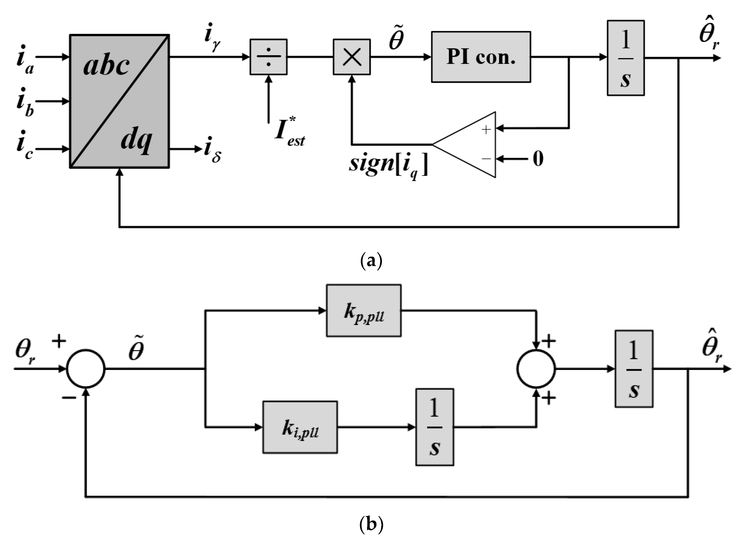
Figure 1. Structure of the position and speed estimation system. (a) Actual block diagram of the estimator and (b) equivalent block diagram of the actual estimator.
Energies 16 01172 g001
Figure 2. A d-q axis block diagram of the VR implementation based on the discrete inverter model. (a) An actual d-q axis model and (b) a simplified d-q axis model.
Energies 16 01172 g002
Figure 3. The a-phase stator current, actual rotor position, and estimated rotor position waveforms according to the load condition. (a) A resistive load system and (b) a non-resistive load system.
Energies 16 01172 g003
Figure 4. General implementation form of the outer and inner virtual impedance.
Energies 16 01172 g004
Figure 5. Derivative-less forms of a virtual impedance controller. (a) Algebraic approximation and (b) cross-coupling feedback of a current vector [32].
Energies 16 01172 g005
Figure 6. Control block diagram of a VI controller [33].
Energies 16 01172 g006
Figure 7. The d, q axis system block diagrams of the proposed flying start based on the discrete inverter model. (a) The d-axis model and (b) the q-axis model.
Energies 16 01172 g007
Figure 8. Implementation of proposed virtual impedance-based flying start method.
Energies 16 01172 g008
Figure 9. Pole loci of the proposed method with different virtual impedance. (a) Pole distributions at 1000 rpm and (b) pole distributions at 3000 rpm.
Energies 16 01172 g009
Figure 10. A comparison of the conventional flying start method and the proposed flying start method with added VI at 500 rpm. (a) The conventional method and (b) the proposed method.
Energies 16 01172 g010
Figure 11. A magnified comparison of the conventional flying start method and the proposed flying start method with added VI at 500 rpm. (a) The conventional method and (b) the proposed method.
Energies 16 01172 g011
Figure 12. A comparison of the stator current and input of the position/speed estimator during mode transition. (a) Without flying start; (b) the VR-based flying start method; and (c) the proposed flying start method.
Energies 16 01172 g012
Figure 13. Configuration of the IPMSM test bench. (a) The control and measurement part and (b) the M-G set with torque transducer.
Energies 16 01172 g013
Figure 14. Experimental results of the conventional method and its position estimation error at 500 rpm and 1000 rpm. (a) θ r , θ ^ r , Ia, and θ e r r   at 500 rpm; (b) θ r , θ ^ r , Ia, and θ e r r   at 1000 rpm.
Energies 16 01172 g014
Figure 15. Experimental results of the conventional method and its position estimation error at 500 rpm and 1000 rpm. (a) Rv, Ia, and θ e r r   at 500 rpm and (b) Rv, Ia, and θ e r r   at 1000 rpm.
Energies 16 01172 g015
Figure 16. Magnified experimental results of the conventional method with actual position and estimated position at 500 rpm and 1000 rpm. (a) θ r , θ ^ r , and Ia 500 rpm and (b) θ r , θ ^ r ,   and   Ia at 1000 rpm.
Energies 16 01172 g016
Figure 17. Experimental results of the proposed flying start method and its position estimation error at 500 rpm. (a) R v , L v , Ia, and θ e r r ; (b) magnified waveform of (a); and (c) the steady state of the proposed flying start method.
Energies 16 01172 g017
Figure 18. Experimental results of the proposed flying start method and its position estimation error at 1000 rpm. (a) R v , L v , Ia, and θ e r r ; (b) magnified waveform of (a); and (c) the steady state of the proposed flying start method.
Energies 16 01172 g018aEnergies 16 01172 g018b
Figure 19. Magnified experimental results of the proposed flying start method at 500 rpm and 1000 rpm. (a) θ r , θ ^ r , Ia, and θ e r r   at 500 rpm and (b) θ r , θ ^ r , Ia, and θ e r r   at 1000 rpm.
Energies 16 01172 g019
Figure 20. Experimental results comparison of the conventional method and the proposed flying start method during mode transition. (a) The VR-based flying start method and (b) the proposed flying start method.
Energies 16 01172 g020
Table 1. Parameters of the IPMSM drive system used for simulation.
ParameterValueUnit
DC-link voltage200V
Rated power2.5kW
Rated speed1800rpm
Rated current13A
Stator resistance0.22Ω
d-axis nominal inductance2.2mH
q-axis nominal inductance5.9mH
Number of poles4-
Peak line-to-line back EMF constant56.7V/krpm
Disclaimer/Publisher’s Note: The statements, opinions and data contained in all publications are solely those of the individual author(s) and contributor(s) and not of MDPI and/or the editor(s). MDPI and/or the editor(s) disclaim responsibility for any injury to people or property resulting from any ideas, methods, instructions or products referred to in the content.