Article

CFD Simulation Study on the Air Side of a CO2 Evaporator in a Motor Train Unit Air Conditioning System

School of Locomotive and Rolling Stock Engineering, Dalian Jiaotong University, Dalian 116028, China
*
Author to whom correspondence should be addressed.
Energies 2023, 16(3), 1037; https://doi.org/10.3390/en16031037
Submission received: 15 December 2022 / Revised: 8 January 2023 / Accepted: 12 January 2023 / Published: 17 January 2023
(This article belongs to the Special Issue Current Status on the Thermal Management of Electric Vehicles)

Abstract

:
At present, China’s high-speed rail is in a period of rapid development. Most of the refrigerants used in Chinese motor train units at this stage are still R134a and R407c, which have an impact on the environment. In response to the environmental protection concept of green travel, it is of great significance to study the air conditioning system of motor train units using CO2 refrigerant. Using CFD simulation analysis technology, the heat transfer performance of the air side of the CO2 finned tube evaporator used in the air conditioning system of the motor train unit is studied. We select the air outlet temperature, pressure drop, heat transfer factor, and resistance factor as the objective function, in addition, monitoring points are set up in the air flow channel to monitor the turbulent flow field and pipe wall pressure. Our research shows that the cooling capacity of the CO2 evaporator can reach up to 29.76 kW, which can meet the heat exchange required in the air conditioning system of the motor train unit. In order to obtain a better structure and the conditions of the heat transfer effect, structural optimization was conducted. The simulation results demonstrate several trends: (i) With the augment of the air inlet velocity, the cooling capacity of the evaporator increases and the heat exchange effect improves; when the air inlet ve > 2.2 m/s, the effect of continuing to augment ve on heat exchange is weak. (ii) Following appropriate reduction of the diameter of the heat exchange tube, the wind resistance is reduced and the cooling capacity of the evaporator is improved. (iii) With the enlargement of the fin spacing, the turbulent motion in the flow channel can be fully developed, there is a peak in the change in the heat exchange tube area optimization factor, and the optimal fin spacing is between 1.6 mm and 1.7 mm; at this time, the average turbulent kinetic energy of the air side is larger and the turbulent dissipation rate is smaller. These results provide a reference for the practical application of CO2 refrigerant in the motor train unit.

1. Introduction

The refrigerant is the “blood” of an air conditioning system. The properties of refrigerant directly affect the performance of the whole system and have different degrees of impact on the environment. Considering a series of negative effects caused by the destruction of nature by unnatural refrigerants, developed countries and regions have begun to restrict the use of HFCs early. According to EU regulations, R744 (CO2) or R729 (air) is recommended as an alternative refrigerant for train air conditioning [1]. Driven by legislative requirements for environmentally friendly refrigerants, the use of CO2 refrigerants has become one of the future options for reducing the impact of air conditioning refrigerants on global warming. Nowadays, as China’s high-speed railway is in a golden period of rapid development, the importance of researching CO2 motor train unit air conditioning system is highlighted.
In relevant research conducted by scholars at home and abroad, Liu et al. [2] used Fluent software to study the corresponding relationship between fluid velocity, pressure change, and fluid turbulence performance at different positions in the heat exchanger flow channel. Gao et al. [3] proposed a design scheme for the refrigerant flow path for a small diameter finned tube heat exchanger and proved its rationality by three-dimensional numerical simulation. Liu et al. [4] used the numerical simulation method to study the manner in which the cooling flow and heat transfer characteristics of supercritical CO2 in horizontal tubes are closely related to the change in temperature field. Fei et al. [5] used a multi-objective genetic algorithm to optimize the structure of straight fins. Jang et al. [6,7] studied the CO2 air conditioning system of trains under different modes, finding that the COP of the air conditioning system of trains with CO2 as the refrigerant is higher, and proposing a correlation between the outlet temperature of the heat exchanger and the optimal high pressure in the CO2 air conditioning system of trains. Zhang et al. [8] showed that the optimal heat exchanger diameter corresponding to different refrigerants was different when the heat transfer was constant. Ding et al. [9] studied the effect of heat exchange tube thinning on the performance and manufacturing process of air conditioners. Li et al. [10] used CFD numerical simulation to study the relationship between the number of different tube rows and the volumetric heat transfer capacity of the heat exchanger in the heat recovery of the small heat pipe for high-speed railway carriages in winter and summer and obtained the optimal number of tube rows for the comprehensive performance of the heat exchanger. Presently, although many scholars have studied the structure of the heat exchanger, the use of CO2 environment-friendly refrigerants to the motor train unit remains scarcely researched.
The purpose of this paper is to discuss the feasibility of using environmentally friendly refrigerant CO2 in motor train unit air conditioning systems. In addition, in order to improve the heat transfer effect, different optimization schemes are proposed for the evaporator structure, which provides a theoretical reference direction for practical applications in future projects.

2. CO2 Motor Train Unit Air Conditioning System

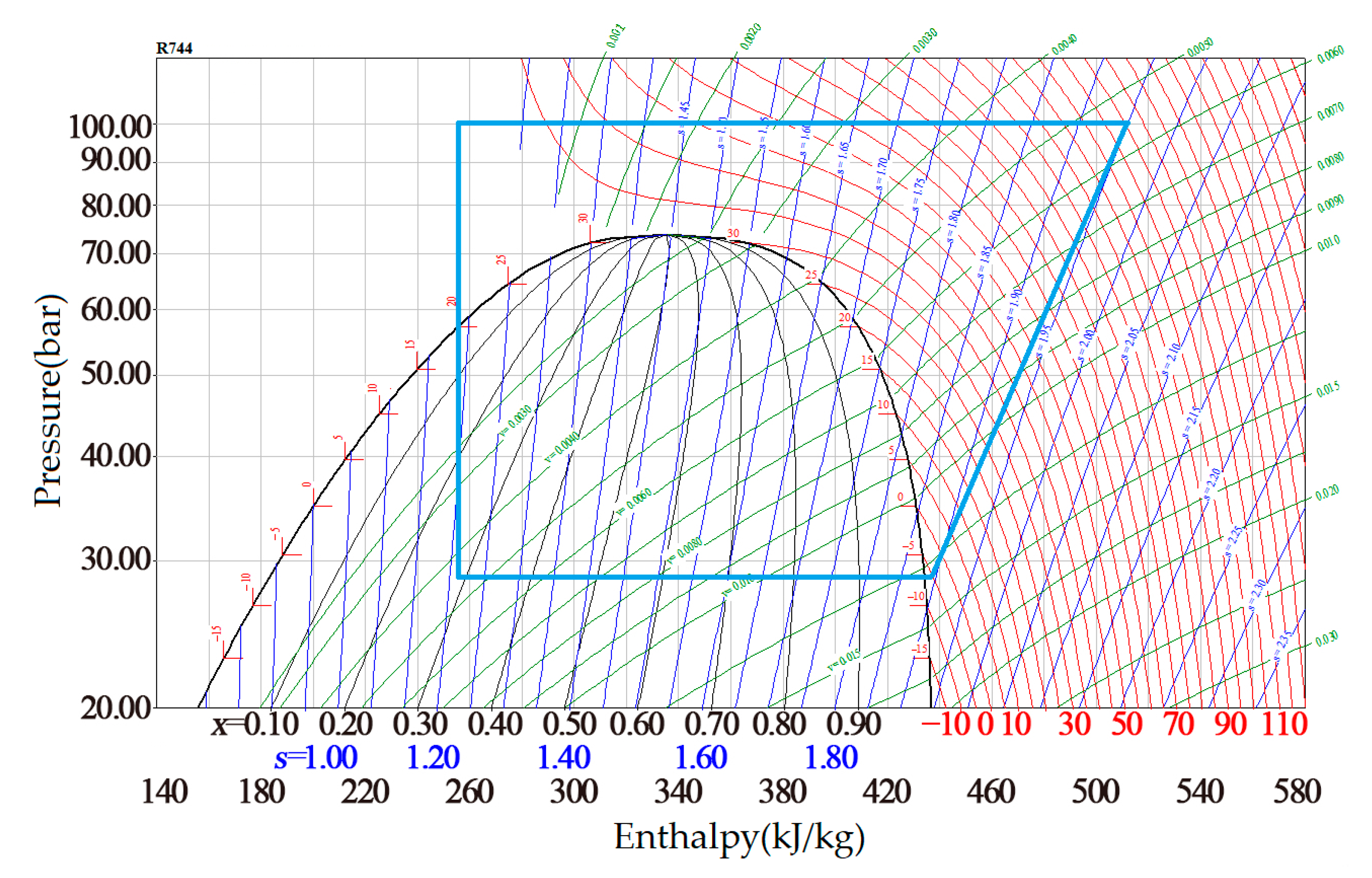
2.1. Characteristics of CO2 Refrigerant

Table 1 compares the characteristics of CO2 with other refrigerants [11]. CO2 is a colorless and odorless gas at normal temperature and pressure with a good thermal performance and environmental performance. As a non-flammable natural refrigerant, it has an ozone-depletion potential and GWP (global warming potential) that can be ignored.
It can be seen from Table 1 that the cooling capacity of CO2 is 5–10 times that of other traditional refrigerants. Its specific pressure is 0.47, much higher than that of conventional fluids. In addition, CO2 has a lower critical temperature (31.1 °C) and a higher critical pressure (7.38 MPa), it cannot transfer heat to an environment above this critical temperature by condensation as a conventional vapor compression cycle can, and the heat transfer process above the critical point leads to the transcritical cycle. The pressure–enthalpy diagram of CO2 refrigerant is displayed in Figure 1 [12]. In Figure 1, the blue box represents a transcritical cycle of CO2 refrigerant in the EMU air conditioning system. The red line is the isotherm, the blue line is the isentropic line, and the green line is the isocapacitive line. The high-pressure side pressure and temperature in the supercritical region are not coupled and can be independently adjusted to obtain the best operating conditions. The CO2 constant pressure heat release process involving the transcritical cycle is carried out in a gas cooler.

2.2. Air Conditioning Refrigeration System Equipment

Compared with the automobile air conditioning system, the motor train unit air conditioning system can possess a greater heat transfer space in the heat exchanger, and the fan system can also provide a larger air flow, which makes the evaporation temperature in the motor train unit air conditioning system of carbon dioxide higher and the pressure difference smaller. As an air conditioning system used on the motor train unit, it requires a greater cooling capacity and more stable operation guarantee. Therefore, two independent circuits are used in the air conditioning system of the motor train unit [6]. Even if one of them fails, the other circuit can ensure the normal operation of the air conditioning in the carriage.
Besides these considerations, the designed air conditioning system needs to meet a certain cooling capacity. The air conditioning system of the motor train unit adopts a double-loop form to increase the cooling capacity. In addition to the piping layout, the components of the two circuits are basically the same, consisting of a compressor, gas cooler, evaporator, expansion valve, and internal heat exchanger. Among them, the compressor adopts a semi-closed reciprocating compressor suitable for the CO2 transcritical cycle and—considering the high operating intensity requirements of motor train unit air conditioning system and high difficulty of maintenance and cleaning—the evaporator and gas cooler adopt a finned tube heat exchanger structure, which has the advantages of strong frame design, easy cleaning, and good market practicability. The length, width, and depth of the evaporator are 1400 mm, 441.5 mm, and 67 mm respectively [6]. The internal heat exchanger uses a coaxial tube heat exchanger to improve system performance. The expansion valve adopted is an electronic expansion valve; through the precise adjustment of the expansion valve opening, the pressure can be better controlled.

3. Calculation Model of Evaporator

3.1. Heat Transfer Calculation
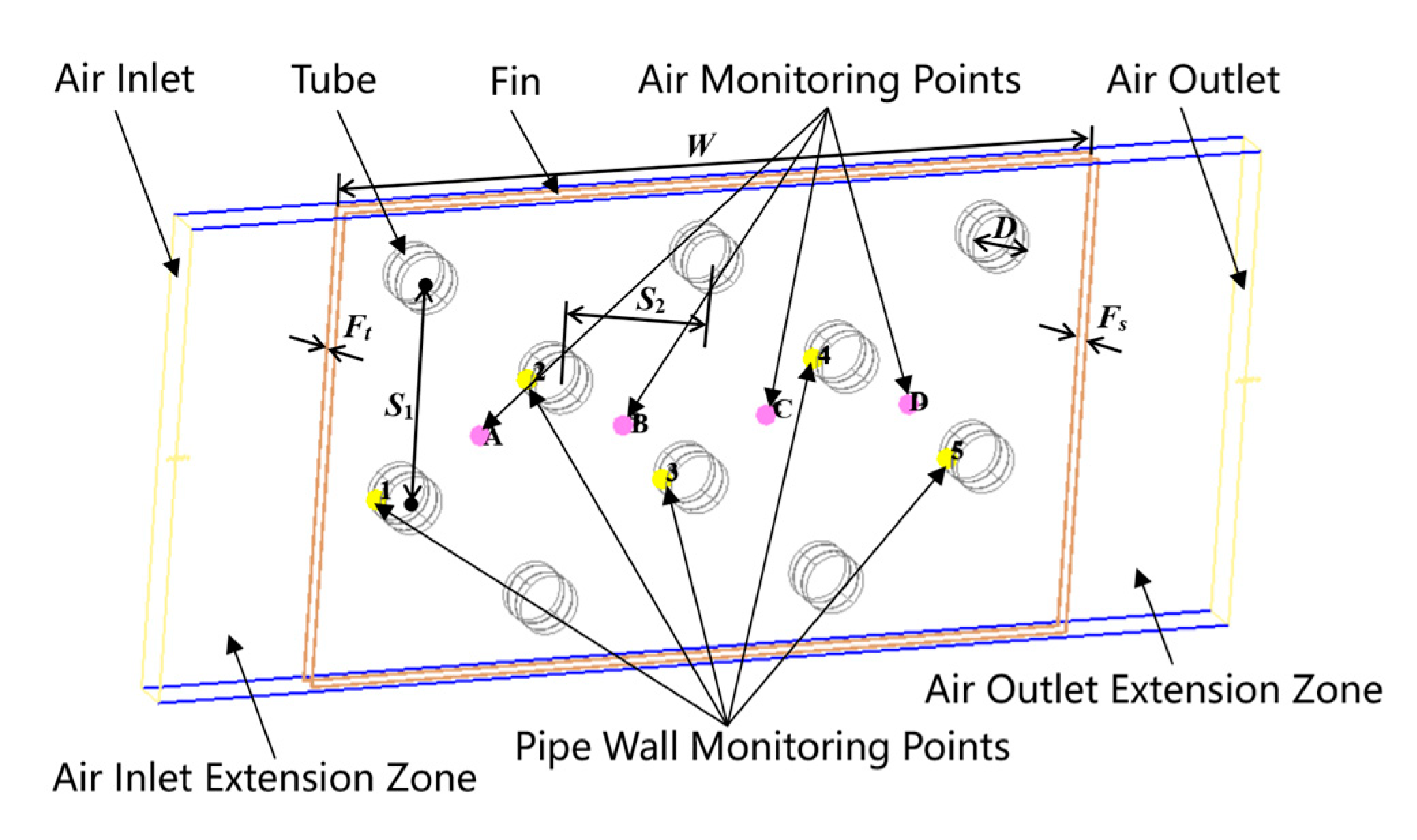
The basic working principle of the evaporator of the motor train unit air conditioning system is that after the low temperature and pressure gas–liquid mixed refrigerant enters the evaporator, the heat flowing through the air outside the absorption tube in the evaporator is vaporized and then flows out of the evaporator. The air outside the tube releases heat and the temperature drops. The heat transfer formula of the evaporator [13] is:
Q 0 = K e A e Δ t e
In the formula, Q0 is the heat transfer of the evaporator, W; Ke is the heat transfer coefficient of the evaporator, W/(m2·°C); Ae is the heat transfer area of the evaporator, in m2; Δ t e is the logarithmic mean heat transfer temperature difference, in °C.
Δ t e = t 1 t 2 ln t 1 t e t 2 t e
In the equation, te is the evaporation temperature, in °C; t1, t2 are the inlet and outlet air temperature of evaporator, in °C.
The heat transfer correlation of flat fins [14,15] is as follows.
N u = 0.982 R e 0.424 F s D 0.0887 N S 2 D 0.159
In the formula, N is the number of tube rows; Fs is the fin spacing, in m; S2 is the tube spacing in the horizontal direction, in m; D is the outer diameter of the tube, in m.
The Reynolds number in the flow channel is calculated with fin spacing as the feature size:
R e = ρ a u i n F s μ a
In the formula, uin is the air velocity at the minimum section of the flow channel, in m/s; ρ a is the air density, in kg/m3; μ a is the aerodynamic viscosity, in Pa∙s.
The heat transfer factor j and the resistance factor f are the main factors affecting the heat transfer and pressure drop of the air side of the heat exchanger. The separate evaluation of the two factors cannot fully analyze the performance of the heat exchanger. However, the heat exchanger area optimization factor j/f can be used as a general evaluation criterion to measure the heat exchanger performance.
Heat transfer factor j calculation formula [16,17]:
j = N u R e · P r 1 / 3
where Nu is the Nusselt coefficient; Pr is the Prandtl coefficient.
Resistance factor f calculation formula:
f = 2 Δ P · A c ρ a u i n 2 A 0
In the formula, Δ P is the inlet and outlet air pressure drop, in Pa; A 0 is the total heat exchange area including fins and heat exchange tubes, in m2; A c is the minimum cross-sectional area of the channel, in m2.

3.2. Physical Model

This paper aims to present the structure of the evaporator in the air conditioning refrigeration system of a motor train unit. The calculation model was established by Icepak software to simulate the heat transfer process on the air side of the CO2 evaporator. After modeling, flexible meshing can be achieved through the “generate mesh” function. After the mesh quality reaches the standard, the boundary conditions of the simulation calculation can be set, then the calculation is completed by the FLUENT solver of the software through the finite volume algorithm. It is worth mentioning that the multi-point discrete solution algorithm used in the software can accelerate the solution time.
In agreement with the simulation model of the 505-Sine evaporator from Lordan [18], the outer diameter of the tube is 5 mm, the vertical tube spacing is 19.05 mm, the horizontal tube spacing is 12.7 mm: the specific dimensions are shown in Table 2.
Considering the complexity of the overall model and the calculation cycle and calculation cost, the calculation model is simplified. The straight finned tube heat exchanger has periodic symmetry and is simplified in turn according to its upper, lower, left, and right edges. In order to ensure the full development of the air movement, the model set up the import and export extension area. In fluid dynamics, a point in the flow field where the local velocity is zero is called a stagnation point. The Bernoulli equation demonstrates that the static pressure is the highest when the velocity is zero, that is, the static pressure is the maximum at the stagnation point. Therefore, the stagnation points 1~5 of each heat exchange tube in the middle two rows are taken as the pressure-monitoring points to monitor the maximum pressure of the heat exchange tube surface. In addition, four monitoring points A, B, C, and D were evenly set in the air flow channel to monitor the average turbulent kinetic energy and turbulent dissipation rate on the air side. The simplified calculation model of the unit finned tube evaporator is shown in Figure 2.
The hexahedral unstructured mesh is selected to divide the calculation model, and the final mesh obtained after multiple refinements is shown in Figure 3.
In IcePak software, the mesh quality is mainly judged by “face alignment”, “volume”, and “skewness” [19]. A “face alignment” and “skewness” closer to 1 mean a better mesh quality. The “volume” criterion is a minimum unit volume greater than 1 × 10⁻¹² m3. The total number of volume cells in the numerical mesh for the model is 454,022. As shown in Figure 4, “face alignment” and “skewness” are close to 1, and the “volume” range is 8.86 × 10⁻¹² m3~6.42 × 10⁻¹⁰ m3. In summary, the mesh quality of the model is good.

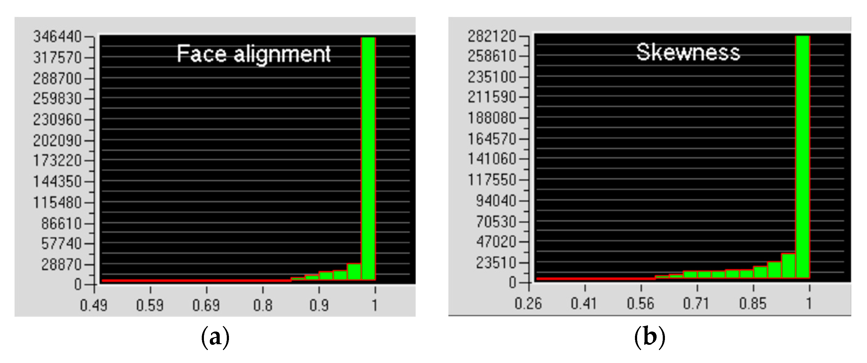
3.3. Boundary Conditions and Grid Division

It is verified that the fluid motion inside the computational model is turbulent. The semi-empirical standard k-ε model is used to simulate the heat transfer process by solving the continuity equation, energy equation, and momentum equation. Assuming that the fins are isotropic, and the fins and heat exchange tubes are made of copper, the air side is set as the velocity inlet, and it is assumed that the temperature in the heat exchange tube is constant when the evaporator works, and the inlet fluid flow distribution is uniform. The heat exchange tube section is short and, as a result, the influence of gravity is ignored. It is assumed that the physical properties of air and CO2 do not change with temperature. Each channel spacing is uniform, and the ventilation and heat transfer situation is the same. The influence of fluid viscous dissipation on fluid motion is ignored. According to the test conditions, the inlet air temperature is determined to be 31.7 °C, and the air density, specific heat capacity at constant pressure, and dynamic viscosity are ρ a = 1.1095   kg / m 3 , c p , a = 1.005   kJ / kg · K , and μ a = 1.86 × 10 5   Pa · s , respectively. Specific motor train unit air conditioning system a refrigeration cycle of the basic parameters is shown in Table 3.

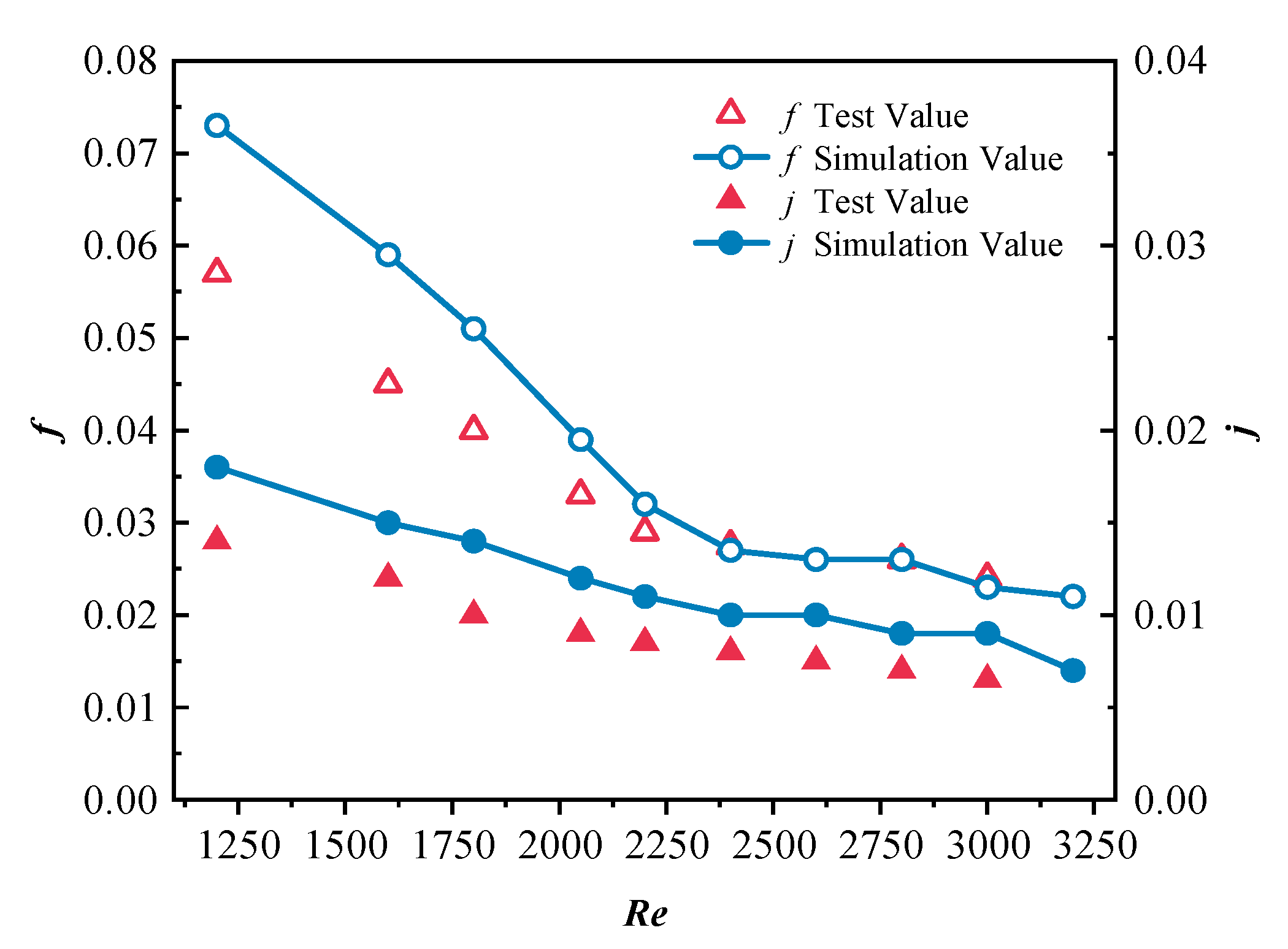
3.4. Simulation Reliability Verification

To ensure the accuracy and reliability of the simulation results, the simulation uses the same structural parameters as the CFD model used by Wahiba et al. [20], which is used to test the effect of non-uniform inlet gas distribution on the thermal hydraulic performance of heat exchangers: The fin spacing is Fs = 2 mm; fin thickness, Ft = 0.14 mm; tube outer diameter, D = 9.97 mm; heat exchange tube longitudinal spacing, S1 = 20.4 mm; and the transverse spacing of the heat exchange tube is S2 = 17.5 mm. At the upstream inlet boundary, Dirichlet boundary conditions, a uniform flow with constant velocity vin, and a constant temperature Tin are assumed. At the downstream end of the computational domain or outlet, the Neumann boundary condition is applied, as all the variables are set to zero. According to the study of boundary layer division of flow around a cylinder [21,22], the critical Reynolds number is 1300. By changing the inlet air velocity of the evaporator, the Reynolds number Re is changed to complete the performance test of the evaporator under different working conditions. The resistance factor f and heat transfer factor j are used as a function of the Reynolds number Re in the range of 1200~3200 to compare the simulation results with the experimental data. The comparison data of simulation values and experimental values are shown in Table 4. Figure 5 shows the comparison of simulation values and experimental values of the resistance factor f and heat transfer factor j. It was calculated that the root mean square error of the drag factor f is 0.88%, and the root mean square error of the heat transfer factor j is 0.31%. It was verified that the simulation value is in good agreement with the experimental value, so the numerical simulation results are reliable.

4. Analysis and Discussion of Simulation Results

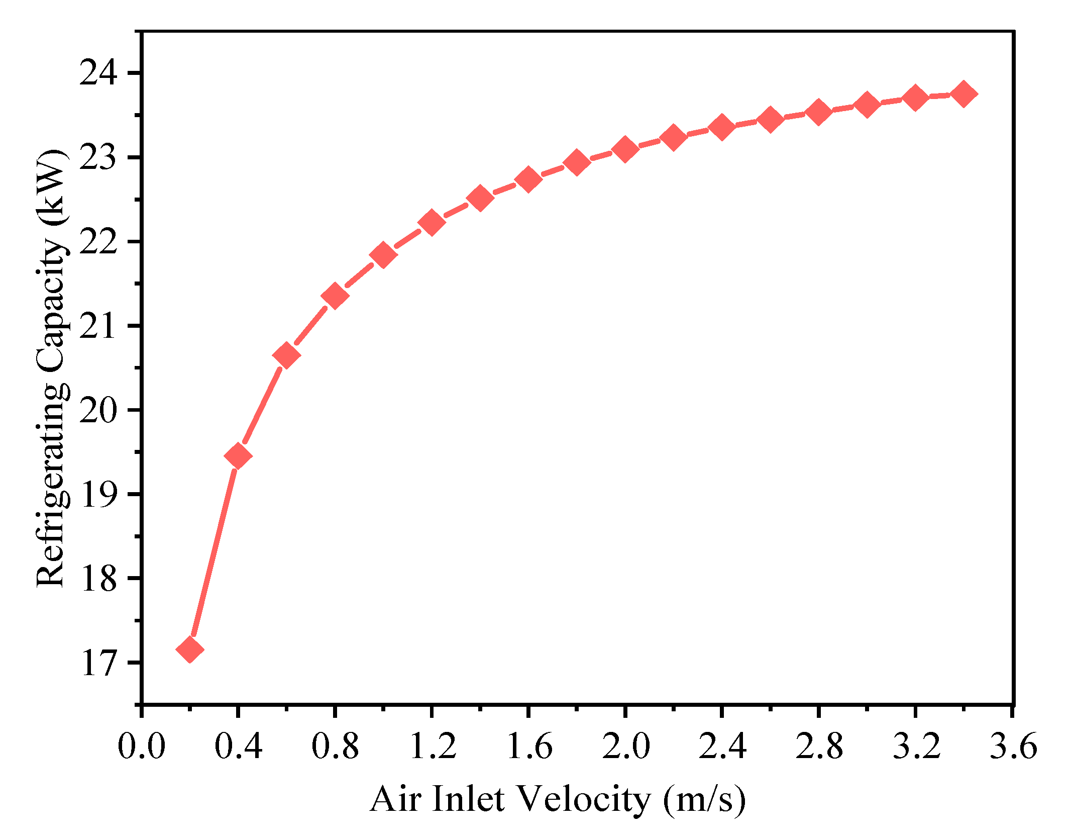
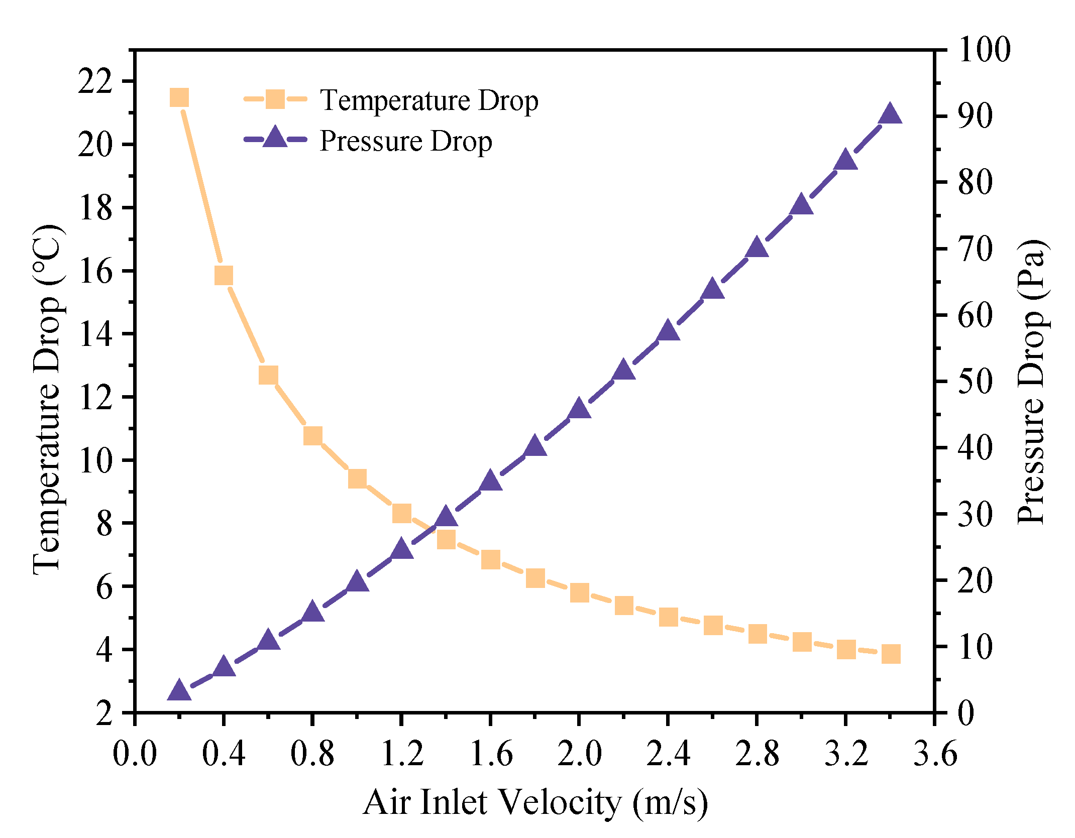
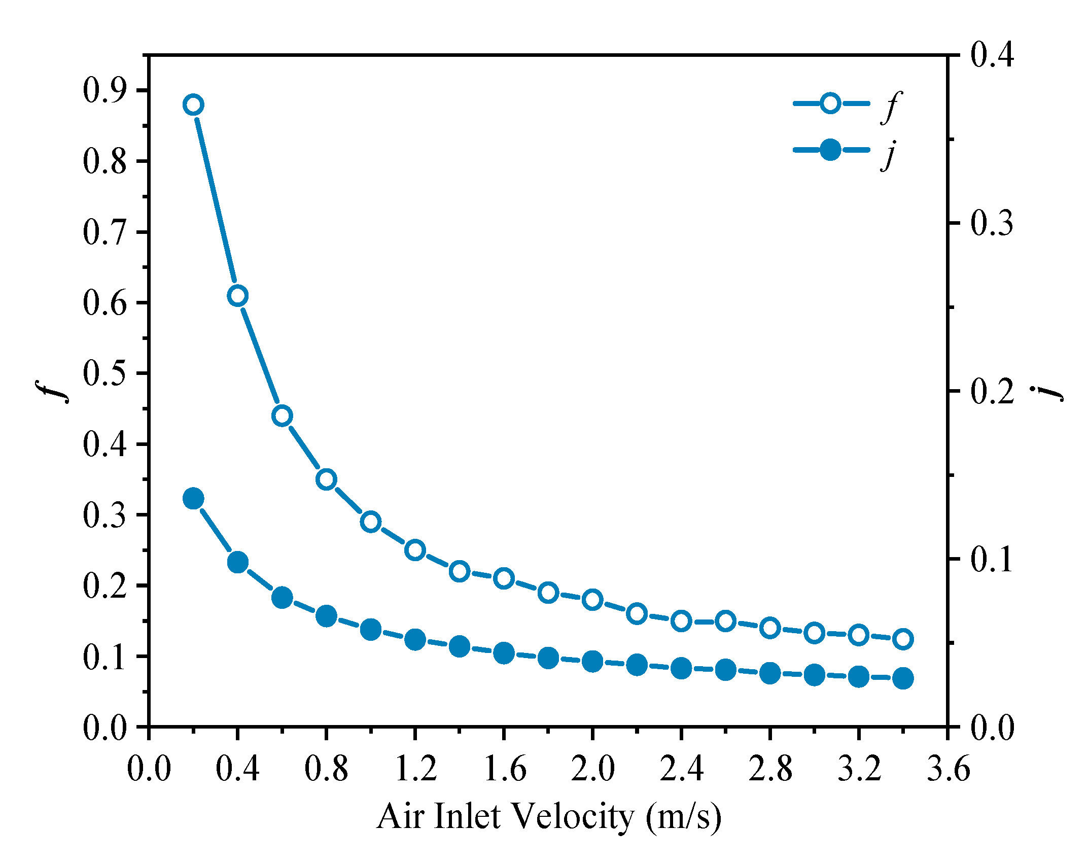
4.1. Effect of Frontal Wind Speed on the Heat Transfer Performance of the Evaporator

In order to explore the influence of the frontal wind speed on the heat transfer performance of the evaporator, the frontal wind speed of the evaporator, that is, the air inlet velocity, is gradually increased from 0.2 m/s to 3.6 m/s at an interval of 0.2 m/s. A simulation analysis was carried out to obtain the change in each parameter in the refrigeration cycle with the increase in air inlet velocity. Figure 6, Figure 7, Figure 8 and Figure 9 show the effects of inlet air velocity on the cooling capacity, air side temperature drop and pressure drop, heat transfer factor j and resistance factor f, and heat exchanger area optimization factor j/f, respectively.
It can be seen from Figure 6 and Figure 7 that as the air inlet flow rate grows, the overall cooling capacity increases, the temperature difference between the inlet and outlet of the air side decreases, and the change range reduces gradually with the increase in the flow rate. After the air inlet velocity reaches 2.0 m/s, it tends to be gentle. At this time, the air inlet velocity has little effect on the overall cooling capacity and air outlet temperature. It can be observed that on the basis of keeping other conditions unchanged, suitably increasing the frontal wind speed on the air side is beneficial to improve the heat transfer effect of the evaporator. However, the air outlet pressure drop climbed with the augment of air inlet velocity, so it is necessary to consider the influence of various factors to obtain the optimal solution.
The drag factor f and the heat transfer factor j were attenuated under the influence of increasing air inlet velocity ve, as shown in Figure 8. When the ve value is in the range of 0.2~1.2 m/s, the decrease is larger; when ve > 1.2 m/s, the decreasing trend tends to be gentle; when ve > 2.4 m/s, the air replacement rate increases in speed, the contact heat transfer time becomes shorter, and the reduction can be ignored. Figure 9 presents the variation in j/f with air inlet velocity. The j/f value increases with the augment of air inlet velocity. When the ve value is in the range of 0.2~1.4 m/s, the j/f value exhibits a large rise, and the change trend of j/f value becomes gentle after ve > 1.4 m/s. Following the further increasing of the air inlet velocity to 2.0 m/s, the j/f value slightly climbs. When ve > 2.2 m/s, the j/f value tends to become stable again. Considering the fan power consumption and the degree of superheat, combined with the simulation data, the flow rate of the air side inlet of the CO2 evaporator is set between 1.4 m/s and 2.2 m/s to obtain a better heat transfer effect.

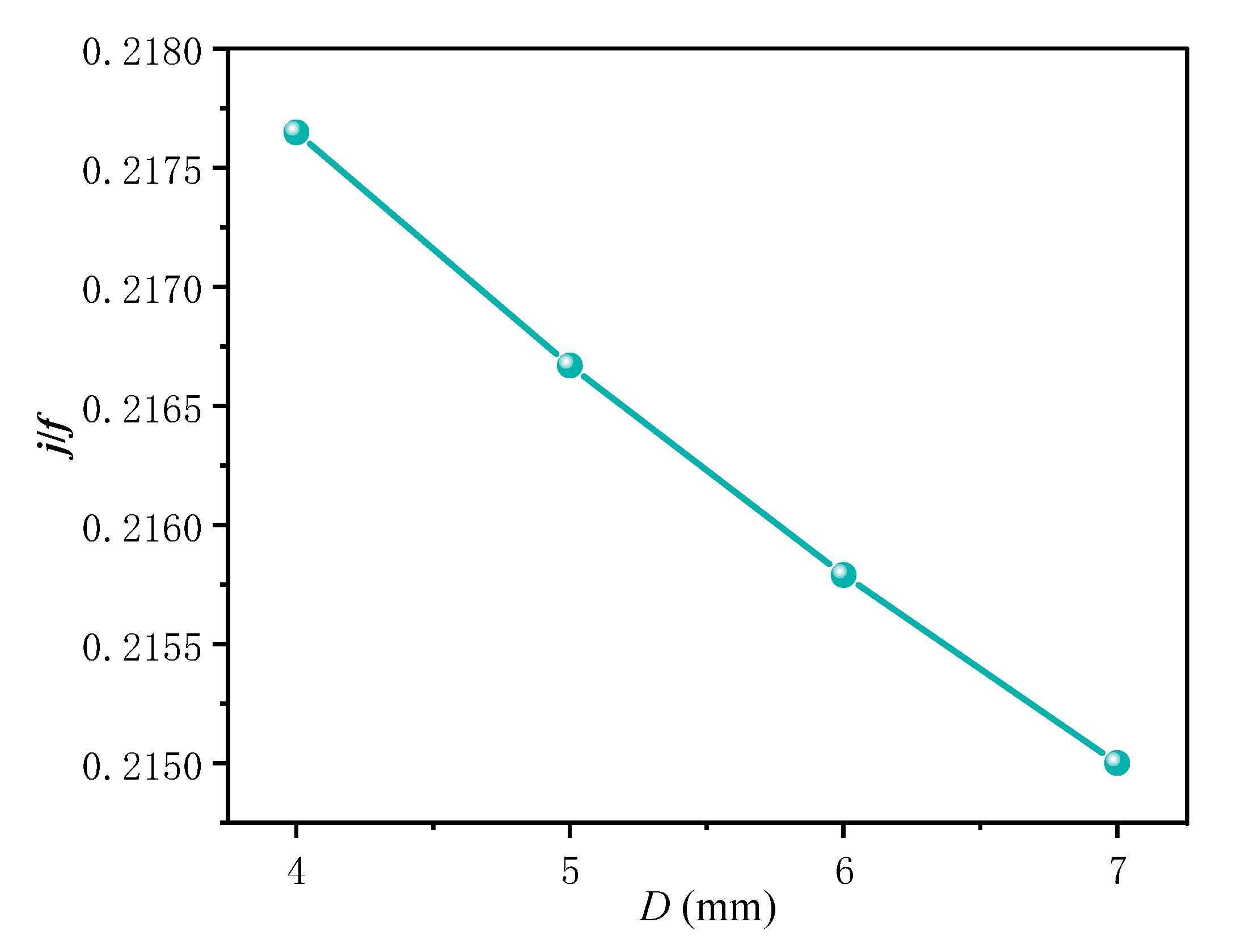
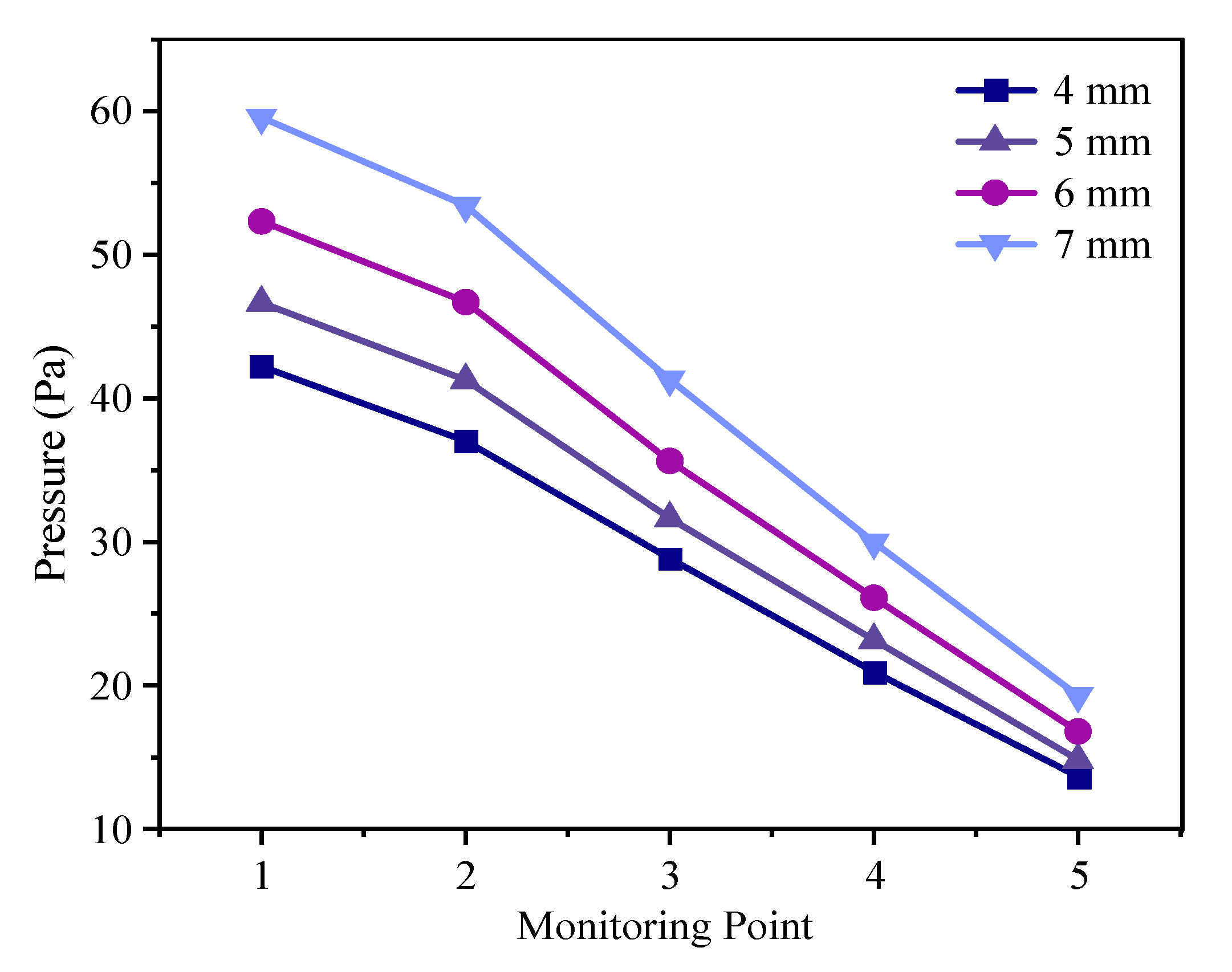
4.2. Effect of Outer Diameter of the Heat Exchange Tube on the Heat Transfer Performance of the Evaporator

The outer diameter of the original model tube is 5 mm. Presently, finned tube evaporators with outer diameters of 4 mm, 5 mm, 6 mm, and 7 mm are simulated and analyzed, respectively. We take ve = 2.0 m/s in order to obtain the effect of pipe diameter on the air side outlet temperature and wind resistance of the evaporator and the average turbulent kinetic energy and the turbulent dissipation rate at monitoring points A, B, C, and D; the specific simulation data are shown in Table 5. Figure 10 shows the vertical pressure contours of four different diameters. Figure 11 and Figure 12 respectively reflect the change in the area optimization factor j/f and the change in pressure at different monitoring points when the heat exchange tube adopts different diameters.
From Table 5, it can be seen that with the increase in the pipe diameter, the air has a greater contact area with the evaporator heat exchange tube, and the air side temperature drop is accelerated. However, with the aggrandizement of the tube diameter, although the heat transfer area of the tube enlarged, it also occupied a larger fin area, resulting in a reduced fin area, and the heat transfer rate of the fins is diminished. Due to the large number of fins in the evaporator, the total area of reduced fins is greater than the total area of enlarged tubes; the total heat exchange area decreases. Combined with the data of Figure 11, it can be seen that the smaller the pipe diameter, the larger the j/f value of the heat exchange tube. In Figure 12, the wind resistance augmentation with the increase in pipe diameter, and the wind resistance of the rear pipe is obviously smaller than that of the front pipe. This rule can be more intuitively reflected by Figure 10. For CO2 refrigerants, the use of a smaller diameter can provide a greater pressure to ensure that the evaporator works better under high pressure.
Considering that reducing the pipe diameter will enhance the flow resistance of the refrigerant in the pipe, it can be concluded that: Under the premise of ensuring reasonable refrigerant flow resistance, the refrigeration capacity of the evaporator can be improved by reducing the diameter of the heat exchange tube to reduce the wind resistance and enlarge the total heat transfer area of the evaporator. In addition, the values of the wall pressure monitoring points of the heat exchange tube at different positions in the air passage are different; therefore, the evaporator structure can be designed as a smaller pipe diameter in the front row and a larger pipe diameter in the back row to optimize the influence of wind resistance on the heat transfer effect of the evaporator.

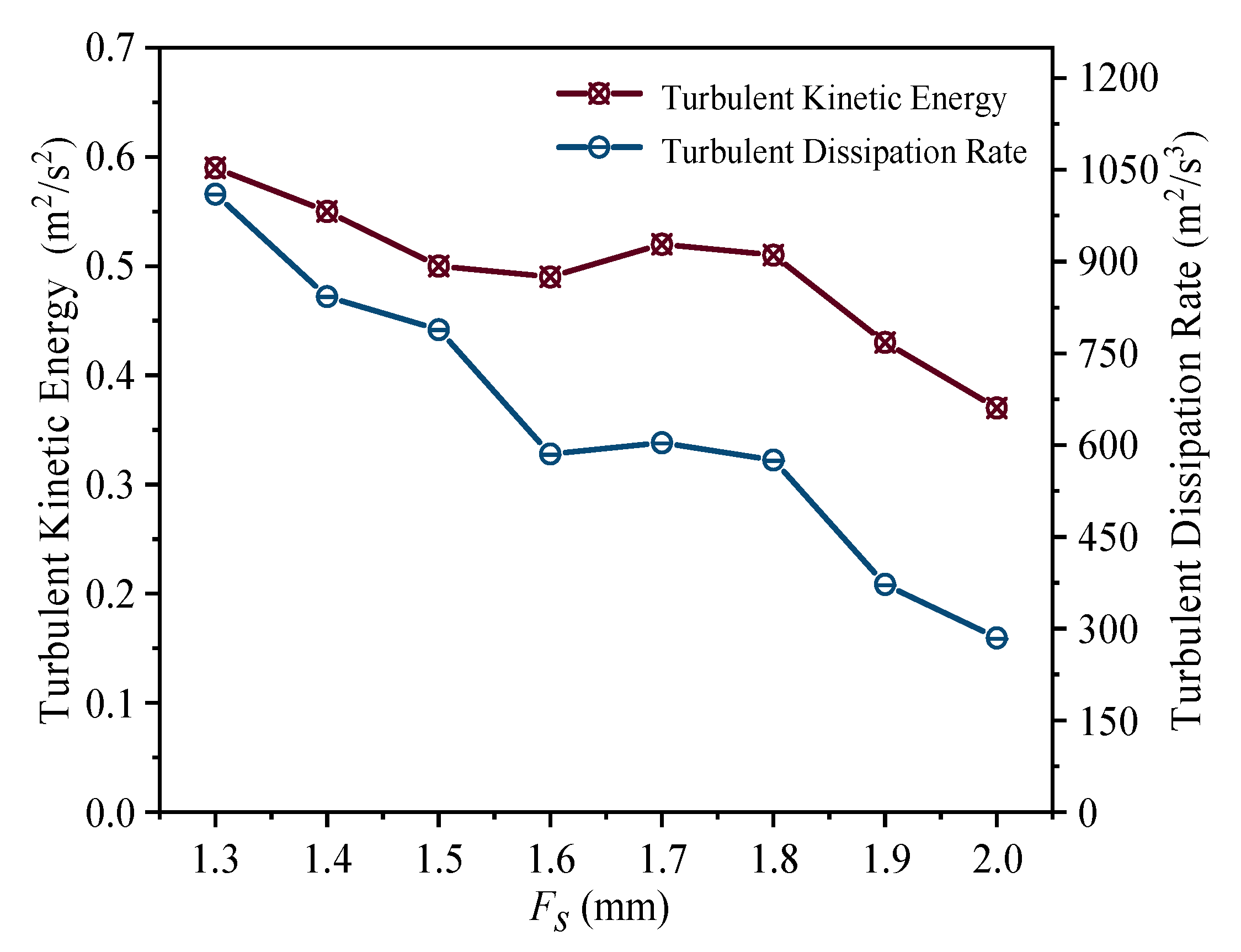
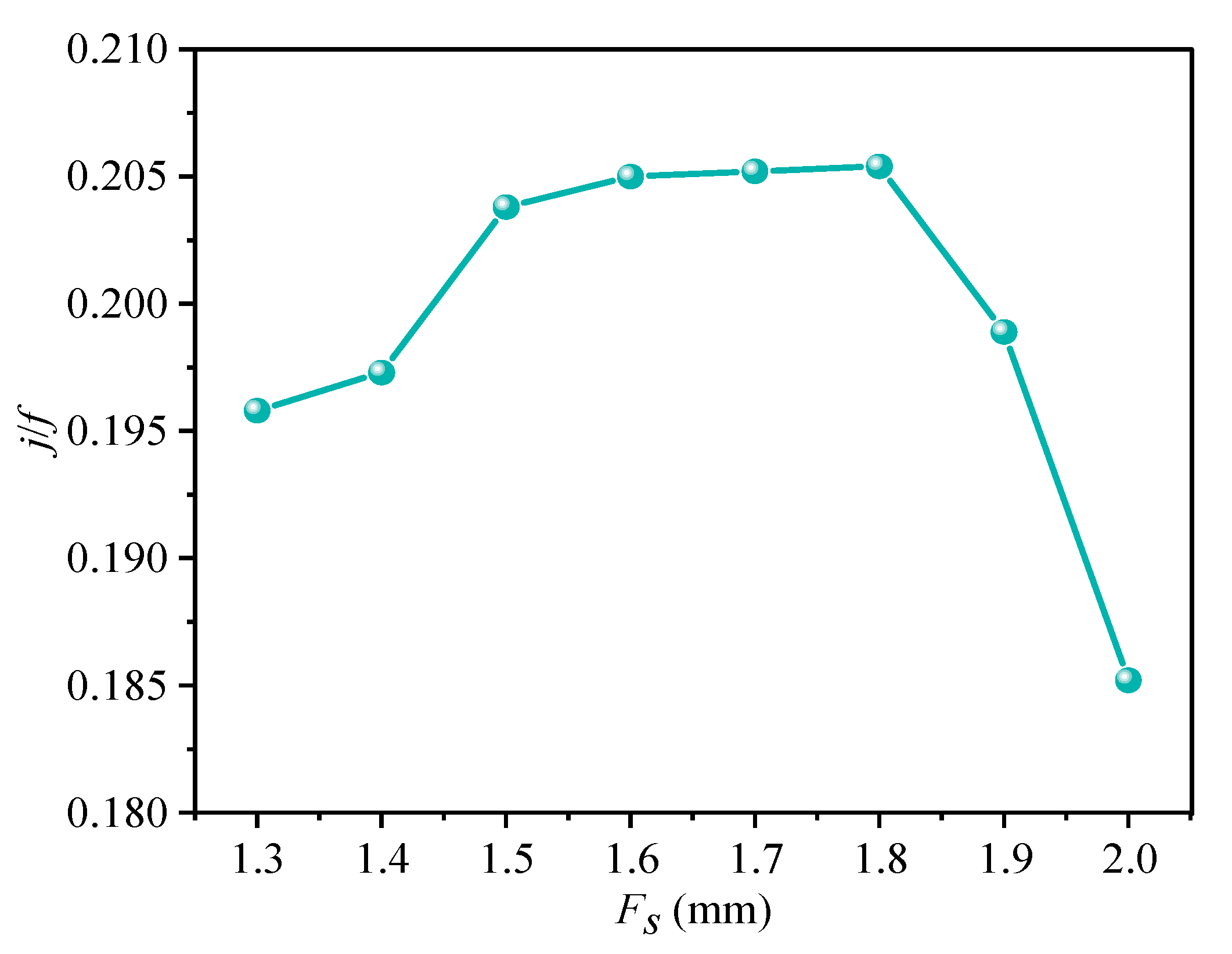
4.3. Effect of Fin Spacing on the Heat Transfer Performance of the Evaporator

The fin spacing of the original model is 1.7 mm. In order to explore the influence of fin spacing on its heat transfer performance, the fin spacing is set to 1.3 mm, 1.4 mm, 1.5 mm, 1.6 mm, 1.7 mm, 1.8 mm, 1.9 mm, and 2.0 mm, respectively, and the air inlet velocity to 2.0 m/s. The simulation analysis of these eight cases was carried out to obtain the influence of different fin spacing on the temperature drop and wind resistance of the evaporator. The simulation data are shown in Table 6. Figure 13 displays the variations of average turbulent kinetic energy and turbulent dissipation rate at monitoring points A, B, C, and D with different fin spacings. Figure 14 displays the influence of different fin spacing on the area optimization factor j/f of the heat exchange tube.
From Table 6, it can be seen that the change in fin spacing has no obvious effect on the temperature drop on the air side. Therefore, the outlet pressure drop and the average turbulent kinetic energy and turbulent dissipation rate of the monitoring points in the air flow process are taken as the main objective functions. When Fs increases, the expansion of the air flow channel enables the turbulent motion in the flow channel to be fully developed, and the pressure drop decreases with the augment of the fin spacing. In order to obtain a better heat transfer effect, it is necessary to select the structure with a larger turbulent kinetic energy and a smaller turbulent dissipation rate. As shown in Figure 13, when Fs ≤ 1.6 mm, the average turbulent kinetic energy and turbulent dissipation rate diminish with the increase in fin spacing. When Fs is in the range of 1.6 mm~1.8 mm, they have a tiny upward trend, and then decrease with the augmentation of the Fs value. Among them, the turbulent dissipation rate decreases greatly after Fs > 1.5 mm; when Fs = 1.6 mm~1.8 mm, the change tends to become stable; and when Fs exceeds 1.8 mm, the decrease amplitude becomes larger again. In Figure 14, with the enlargement of Fs, the area optimization factor j/f increases first and then decreases, there is a peak in the range of Fs = 1.6~1.8 mm. Considering these data comprehensively, the optimal fin spacing is between 1.6 mm and 1.7 mm. In terms of cooling capacity, under the condition that the total volume of the heat exchanger is unchanged, it is beneficial to improve the cooling capacity of the evaporator to reduce the fin spacing appropriately.

5. Conclusions

Through the air-side computational fluid dynamics analysis of the finned tube evaporator unit structure of a certain type of motor train unit with CO2 refrigerant, the simulation results were compared with the experimental data. Then, the air inlet flow rate, the diameter of the evaporator heat exchange tube, and the fin spacing are changed, respectively, and the air outlet temperature, pressure drop, heat transfer factor j, resistance factor f, and heat exchange tube area optimization factor j/f were selected as the objective functions. In addition, monitoring points were set in the air flow channel to monitor the turbulence field and wall pressure, and the heat transfer performance of the CO2 evaporator was analyzed. The main conclusions are as follows:
  • The simulation results are compared with the experimental values to calculate that the root mean square error of the resistance factor f is 0.88%, and the root mean square error of the heat transfer factor j is 0.31%. The simulation results are in good agreement with the experimental values, and the simulation results are reliable;
  • The simulation results demonstrate that the cooling capacity of the CO2 evaporator in the system is up to 29.76 kW, which meets the heat exchange required in the air conditioning system of a motor train unit, and verifies the feasibility of the CO2 evaporator in the air conditioning system of a motor train unit;
  • With the increase in air inlet velocity ve, the cooling capacity of the evaporator and the area optimization factor j/f value of the heat exchange tube are increased, and the heat transfer effect is improved. Taking into account the power consumption of the fan and a certain degree of superheat, a CO2 evaporator air-side inlet velocity between 1.4 m/s and 2.2 m/s can produce a better heat transfer effect;
  • Appropriately reducing the diameter D of the heat exchange tube can reduce the wind resistance, raise the j/f value, and improve the refrigeration capacity of the evaporator; the wind resistance of the rear row tube is smaller than that of the front row tube and thus the structure of the front row small tube diameter and the rear row large tube diameter can be used to optimize the influence of wind resistance on the heat transfer effect of the evaporator;
  • In a certain range, the change in fin spacing has no obvious effect on the air-side temperature drop. With the aggrandizement of fin spacing Fs, the turbulent motion in the flow channel can be fully developed, and the change in j/f has a peak value. The optimal fin spacing is between 1.6 mm and 1.7 mm, at this time, the average turbulent kinetic energy on the air side is larger and the turbulent dissipation rate is smaller.

Author Contributions

Conceptualization, H.C. and X.S.; methodology, Y.G.; software, X.S.; validation, H.C. and Y.G.; investigation, X.S.; data curation, J.F.; writing—original draft preparation, H.C. and J.F. All authors have read and agreed to the published version of the manuscript.

Funding

This research was funded by the Science Researching Plans of Liaoning Provincial Education Department under Grant No. LJKZ0509 and No. LJKFZ20220203. At the same time, this research was funded by the Science and Technology Project of Liaoning Provincial Transportation Department under Grant No. 202242.

Data Availability Statement

Acknowledgments

We would like to thank Dalian Jiaotong University for providing the thermal engineering laboratory for this research and all the laboratory teachers for their hard work.

Conflicts of Interest

The authors declare no conflict of interest.

References

  1. Qin, Y.; Yang, Z.; Wang, B.; Hao, Z.; Han, S. Research progress and development trend of new environmentally friendly refrigerants. Chem. World 2018, 59, 60–64. [Google Scholar]
  2. Liu, J.C.; Zhang, S.Y.; Zhou, Z.Y. Analysis of Channel Structure Improvement and Its Influence on Fluid Flow in Plate-fin Heat Exchanger. J. Mech. Eng. 2014, 50, 167–176. [Google Scholar] [CrossRef]
  3. Gao, J.; Ding, G.; Wu, W.; Gao, Q.; Song, J.; Liu, Z.; Chen, S. Design method of R290 air conditioner small tube diameter finned tube heat exchanger. China Aliance 2012, S1, 335–343. [Google Scholar]
  4. Liu, Z.; Fei, J.; Yang, Y. Study on the influence of pipe diameter on flow heat transfer in supercritical CO2 tubes. J. Eng. Thermophys. 2016, 37, 357–360. [Google Scholar]
  5. Fei, J.; Tian, S.; Wang, F.; Li, H. Optimization of structural parameters of straight finned tubular heat exchangers. J. Dalian Jiaotong Univ. 2018, 39, 40–44. [Google Scholar]
  6. Jiang, F.; Wang, Y.; Yu, B.; Wang, D.; Shi, J.; Chen, J. Effects of various operating conditions on the performance of a CO2 air conditioning system for trains. Int. J. Refrig. 2019, 10, 105–113. [Google Scholar] [CrossRef]
  7. Wang, Y.; Wang, D.; Yu, B.; Shi, J.; Chen, J. Experimental and numerical investigation of a CO2 heat pump system for electrical vehicle with series gas cooler configuration. Int. J. Refrig. 2018, 100, 156–166. [Google Scholar] [CrossRef]
  8. Zhang, H.; Li, J.; Zhao, F.; Huang, Y.; Fan, C.; Liu, H.; Yan, G. Matching characteristics of the refrigerant type to the diameter of the finned tube heat exchanger. J. Refrig. 2019, 40, 56–61. [Google Scholar]
  9. Ding, G.; Wu, G.; Liu, T. Research progress of refrigeration and air conditioning heat exchanger (1)—Small diameter finned tube heat exchanger. J. Aliance Sci. Technol. 2019, 4, 40–45. [Google Scholar]
  10. Li, K.; Zheng, Q. Numerical simulation study of the optimal number of rows for small heat pipe heat exchangers. Build. Energy Environ. 2020, 39, 41–45. [Google Scholar]
  11. Kim, M.H.; Pettersen, J.; Bullard, C.W. Fundamental process and system design issues in CO2 vapor compression systems. Prog. Energy Combust. Sci. 2004, 30, 119–174. [Google Scholar] [CrossRef]
  12. Chen, G.; Bai, G.; Pang, X.; Xu, J.; Zhao, J.; Tao, G.; Wu, S.; Cao, J. Research and realization of CO2 working fluid alication of high-speed EMU air conditioner. Foreign Railw. Locomot. Mot. Car 2021, 5, 8–14. [Google Scholar]
  13. Zhang, X. Thermal Foundation; Higher Education Press: Beijing, China, 2015; pp. 344–356. [Google Scholar]
  14. Zhang, C.L. Fundamentals of Vapor-Compression Refrigeration and Air-Conditioning System Modeling; Chemical Industry Press: Beijing, China, 2013; pp. 77–107. [Google Scholar]
  15. Han, Z.; Wang, G. Fundamentals of Engineering Fluid Mechanics; Beijing Institute of Technology Press: Beijing, China, 2016; pp. 262–289. [Google Scholar]
  16. Liu, N.; Li, H.; Shan, X.; Jin, X. Numerical simulation of air-side heat transfer and flow characteristics in shutter finned tube heat exchangers. Therm. Power Eng. 2021, 36, 70–77. [Google Scholar]
  17. Peng, J.; Zhang, Y.; Xu, Y.; Yang, R.; Yuan, L.; Li, S. Optimization of Staggered Fins Heat Exchangers for Miniaturized Hydraulic Power Units Using Genetic Algorithm. J. Mech. Eng. 2021, 57, 49–57. [Google Scholar]
  18. Christian, L.; René, R. Multi-objective design optimization of a rail HVAC CO2 cycle. Int. J. Refrig. 2018, 92, 133–142. [Google Scholar]
  19. Liu, B. ANSYS Fluent 2020 Comprehensive Alication Case Study Details; Tsinghua University Press: Beijing, China, 2021; pp. 45–72. [Google Scholar]
  20. Wahiba, Y.; Mohamed, G.; Evgueniy, E. 3D CFD study of the effect of inlet air flow maldistribution on plate-fin-tube heat exchanger design and thermal–hydraulic performance. Int. J. Heat Mass Transf. 2016, 101, 527–541. [Google Scholar]
  21. Wang, J.; Wang, X.; Zhu, Q.; Zhao, Y. Flow and Heat Transfer Characteristics of Flow Past the Bluff Body in Turbulent Boundary Layer. J. Mech. Eng. 2015, 51, 168–176. [Google Scholar] [CrossRef]
  22. Tian, S. The Optimization Design and Simulation of Heat Exchanger on Air Conditioning of Rail Transport. Master’s Thesis, Dalian Jiaotong University, Dalian, China, 2018. [Google Scholar]
Figure 1. Pressure–enthalpy diagram of CO2.
Energies 16 01037 g001
Figure 2. Finned tube evaporator unit structure calculation model.
Energies 16 01037 g002
Figure 3. Mesh partition diagram of model.
Energies 16 01037 g003
Figure 4. Mesh quality detection: (a) Results of “face alignment”; (b) Results of “skewness“.
Energies 16 01037 g004
Figure 5. Comparison of numerical simulation and experimental results of the evaporator.
Energies 16 01037 g005
Figure 6. The variation in cooling capacity with air inlet flow rate.
Energies 16 01037 g006
Figure 7. Effect of air inlet velocity on temperature drop and pressure drop.
Energies 16 01037 g007
Figure 8. Effect of air inlet velocity on f and j.
Energies 16 01037 g008
Figure 9. Variation in heat exchanger area optimization factor j/f with air inlet velocity.
Energies 16 01037 g009
Figure 10. Vertical section pressure cloud diagram of four different pipe diameters: (a) Pressure cloud diagram of pipe diameter 4 mm; (b) Pressure cloud diagram of pipe diameter 5 mm; (c) Pressure cloud diagram of pipe diameter 6 mm; (d) Pressure cloud diagram of pipe diameter 7 mm.
Energies 16 01037 g010
Figure 11. The change in j/f with pipe diameter.
Energies 16 01037 g011
Figure 12. Pressure changes at different pipe diameter monitoring points.
Energies 16 01037 g012
Figure 13. The effect of fin spacing on the air-side turbulent motion.
Energies 16 01037 g013
Figure 14. The change in j/f with fin spacing.
Energies 16 01037 g014
Table 1. Characteristics of different refrigerants.
R12R22R134 aR407 cR290R744 c
Ozone Depletion Potential/Global Warming Potential1/85000.05/17000/13000/16000/30/1
Molecular Weight (kg/kmol)120.986.5102.086.244.144.0
Normal Boiling Point (°C)−29.8−40.8−26.2−43.8−42.1−78.4
Critical Pressure (MPa)4.114.974.074.644.257.38
Critical Temperature (°C)112.096.0101.186.196.731.1
Specific Pressure a0.070.100.070.110.110.47
Specific Temperature b0.710.740.730.760.740.90
Unit Volume Refrigerating Effect (kJ/m3)2734435628684029390722,545
a The ratio of saturation pressure to critical pressure at 0 °C. b Ratio of 273.15 K (0 °C) to critical temperature in Kelvin. c The refrigerant R744 is CO2.
Table 2. Finned tube evaporator size.
ParameterValueParameterValue
Evaporator Length L1400 mmTransverse Spacing of Tube S212.7 mm
Evaporator Width W67 mmNumber of Tube Rows N5
Evaporator Height H441.5 mmNumber of Tubes Per Row n23
Tube Inner Diameter D04.4 mmFin TypeFlat
Tube Outside Diameter D5.0 mmFin Thickness Ft0.14 mm
Longitudinal Spacing of Tube S119.05 mmFin Spacing Fs1.7 mm
Table 3. A refrigeration cycle loop condition in a motor train unit air conditioning system.
ParameterValue
Ambient Air Temperature/°C35
Influence of Air Relative Humidity/%50
Mixed Air Temperature/°C31.7
Relative Humidity of Mixed Air/%42
RefrigerantR744 (CO2)
Evaporation Temperature of Refrigerant/°C−7
Total Cooling Capacity of The Evaporator/kW22.5
Table 4. Evaporator simulation and test results comparison data.
Re1200160018002100220024002600280030003200
f Test Value0.0570.0450.040.0330.0290.0275/0.0260.024/
f Simulation Value0.0730.0590.0510.0390.0320.0270.0260.0260.0230.022
j Test Value0.0140.0120.0100.0090.00850.0080.00750.0070.0065/
j Simulation Value0.0180.0160.0140.0120.0110.0100.0100.0090.0090.007
f Root Mean Square Error0.88%
j Root Mean Square Error0.31%
Table 5. Evaporator simulation data of different diameters.
Outer Diameter of Tube/mm4567
Temperature Drop/°C5.445.836.266.96
Turbulent Kinetic Energy/m2·s−20.560.580.610.67
Turbulent Dissipation Rate/m2·s−3803.81839.24900.711008.59
Heatsink Transfer Factor j0.0370.0390.0410.043
Resistance Coefficient f0.170.180.190.20
Refrigerating Capacity/kW23.6423.0922.3921.99
Table 6. Simulation data of evaporator with different fin spacing.
Fs/mm1.31.41.51.61.71.81.92.0
Average Outlet Air Temperature/°C25.9225.9325.9025.8525.8525.8825.7825.79
Pressure Drop/Pa81.1671.8061.1358.0948.6348.9145.0042.09
Turbulent Kinetic Energy/m2·s−20.590.550.500.490.520.510.430.37
Turbulent Dissipation Rate/m2·s−31010.34842.78788.95585.76603.83575.87372.42284.80
Heatsink Transfer Factor j0.0470.0450.0430.0410.0390.0380.0370.035
Resistance Coefficient f0.2400.2280.2110.2000.1900.1850.1860.189
Refrigerating Capacity/kW29.7627.7425.9624.4123.0722.0120.8920.08
Disclaimer/Publisher’s Note: The statements, opinions and data contained in all publications are solely those of the individual author(s) and contributor(s) and not of MDPI and/or the editor(s). MDPI and/or the editor(s) disclaim responsibility for any injury to people or property resulting from any ideas, methods, instructions or products referred to in the content.

