Numerical Modeling of Two-Phase Flow inside a Wet Flue Gas Absorber Sump
Abstract
:1. Introduction
2. Flue Gas Scrubbing
2.1. Physical Background
2.2. Scrubber (Absorber) Design
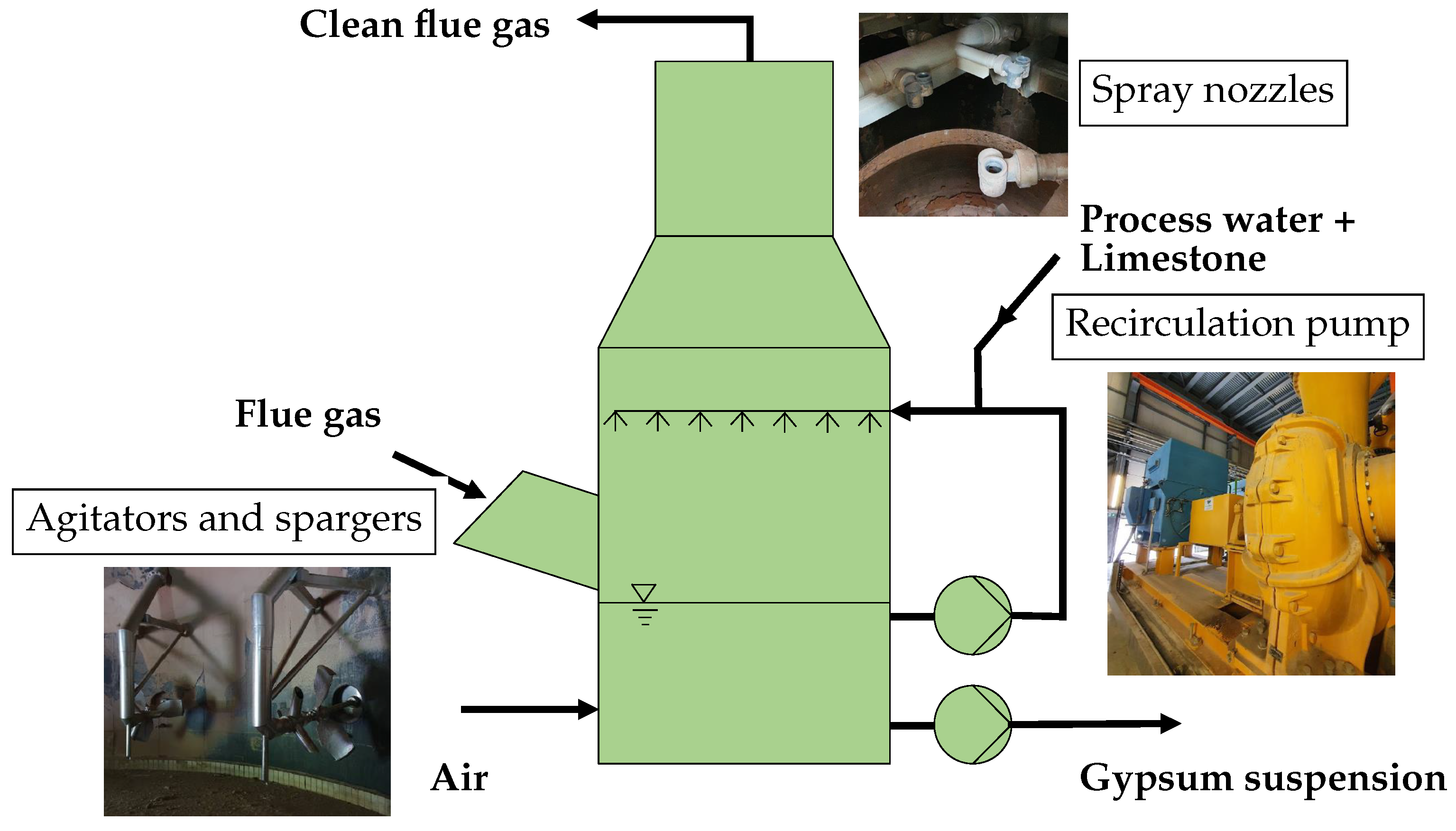
- The air dispersion required for the forced oxidation of CaSO3 is achieved by a combination of agitators and air spargers. An example of agitators with corresponding air spargers in a reference project at the Trbovlje Thermal Power Plant (TET) (Slovenia) is shown in Figure 2b. The design of the sump in TET is different from the design we investigated in this study. Instead of a single sparger on the agitator, air is blown into three points in front of the agitator, as shown in the figure.
- The suspension of gypsum and limestone particles to prevent them from settling, thus eliminating the risk of a solid layer forming at the bottom of the absorber sump. The appropriate suspension conditions also create a suitable environment for the growth of gypsum crystals when supersaturation is reached.
- Ensuring volume and, thus, sufficient time for chemical reactions and the absorption of oxygen into the surrounding liquid.
3. Methods
3.1. Governing Equations
3.2. Boundary Conditions
- A mixed boundary condition that enables the inflow of the continuous phase and the outflow of the dispersed phase is applied on the free surface. Since free surface modeling was outside the scope of this research, the applied simplification was allowed.
- The influence of the agitators on the flow field inside of the absorber sump is modeled as a local linear momentum source, since obtaining the exact geometry of the agitator blades can be challenging. The applied linear momentum source was calculated based on the agitator flange axial force provided by the agitator manufacturer.
- The geometry was simplified so that measurement equipment inside of the absorber sump was omitted from the geometry creation.
3.3. Submodels
4. Results
4.1. Validation
4.2. Simulation Results
4.3. Simulation Results with Lower Linear Momentum Source
5. Conclusions
Author Contributions
Funding
Institutional Review Board Statement
Data Availability Statement
Conflicts of Interest
Abbreviations
| FGD | Flue gas desulfurization |
| CFD | Computational fluid dynamics |
| MRF | Moving reference frame |
| CAD | Computer-aided design |
| URANS | Unsteady Reynolds-averaged Navier–Stokes |
Nomenclature
| Variable | Meaning | Subscipt | Meaning |
| volume fraction | phase | ||
| density | mass | ||
| t | time | m | momentum |
| velocity vector | j | size group | |
| bubble size deviation | d | dispersed phase | |
| p | pressure | x and y direction | |
| stress tensor | out | outlet | |
| gravitational vector | air | air at the inlet | |
| momentum vector | rel | relative | |
| momentum source vector | i | cell | |
| V | volume | D | drag |
| dynamic viscosity | p | particle | |
| deformation tensor | c | continuous phase | |
| identity matrix | L | lift | |
| N | number concentration | turbulent dispersion | |
| H | source/sink of bubbles | t | turbulent |
| f | proportion of the individual size group of bubbles | virtual mass | |
| n | total number of size groups | wall lubrication | |
| directions | || | tangential | |
| H | height of the absorber sump | without the hydrostatic contribution | |
| flow rate | sim | simulation | |
| F | force magnitude | r | retention |
| force vector | sp | sparger | |
| C | submodel coefficient | q | type of force submodel |
| d | diameter | ||
| Reynolds number | |||
| kinematic viscosity | |||
| Schmidt number | |||
| normal vector | |||
| standard deviation | |||
| non-dimensional height | |||
| A | cross-sectional area | ||
| relative air–CaSO3 ratio | |||
| Weber number | |||
| r | rotation speed | ||
| surface tension | |||
| pathline vector | |||
| Courant number | |||
| D | Diameter |
References
- Mersmann, A.; Kind, M.; Stichlmair, J. Thermal Separation Technology; Springer: Berlin/Heidelberg, Germany, 2011. [Google Scholar] [CrossRef]
- Córdoba, P. Status of Flue Gas Desulphurisation (FGD) Systems from Coal-Fired Power Plants: Overview of the Physic-Chemical Control Processes of Wet Limestone FGDs. Fuel 2015, 144, 274–286. [Google Scholar] [CrossRef]
- de Salazar, R.O.; Ollero, P.; Cabanillas, A.; Otero-Ruiz, J.; Salvador, L. Flue Gas Desulphurization in Circulating Fluidized Beds. Energies 2019, 12, 3908. [Google Scholar] [CrossRef]
- Srivastava, R.K.; Jozewicz, W. Flue Gas Desulfurization: The State of the Art. J. Air Waste Manag. Assoc. 2001, 51, 1676–1688. [Google Scholar] [CrossRef] [PubMed]
- Poullikkas, A. Review of Design, Operating, and Financial Considerations in Flue Gas Desulfurization Systems. Energy Technol. Policy 2015, 2, 92–103. [Google Scholar] [CrossRef]
- Tesárek, P.; Drchalová, J.; Kolísko, J.; Rovnaníková, P.; Černý, R. Flue Gas Desulfurization Gypsum: Study of Basic Mechanical, Hydric and Thermal Properties. Constr. Build. Mater. 2007, 21, 1500–1509. [Google Scholar] [CrossRef]
- Jian, S.; Yang, X.; Gao, W.; Li, B.; Gao, X.; Huang, W.; Tan, H.; Lei, Y. Study on Performance and Function Mechanisms of Whisker Modified Flue Gas Desulfurization (FGD) Gypsum. Constr. Build. Mater. 2021, 301, 124341. [Google Scholar] [CrossRef]
- Navarrete, I.; Vargas, F.; Martinez, P.; Paul, A.; Lopez, M. Flue Gas Desulfurization (FGD) Fly Ash as a Sustainable, Safe Alternative for Cement-Based Materials. J. Clean. Prod. 2021, 283, 124646. [Google Scholar] [CrossRef]
- Arif, A.; Stephen, C.; Branken, D.; Everson, R.; Neomagus, H.; Piketh, S. Modeling Wet Flue Gas Desulfurization. In Proceedings of the Conference of the National Association for Clean Air (NACA 2015), Bloemfontein, South Africa, 1–2 October 2015. [Google Scholar]
- Marocco, L.; Inzoli, F. Multiphase Euler–Lagrange CFD Simulation Applied to Wet Flue Gas Desulphurisation Technology. Int. J. Multiph. Flow 2009, 35, 185–194. [Google Scholar] [CrossRef]
- Qu, J.; Qi, N.; Li, Z.; Zhang, K.; Wang, P.; Li, L. Mass Transfer Process Intensification for SO2 Absorption in a Commercial-Scale Wet Flue Gas Desulfurization Scrubber. Chem. Eng. Process. Process. Intensif. 2021, 166, 108478. [Google Scholar] [CrossRef]
- Qu, J.; Qi, N.; Zhang, K.; Li, L.; Wang, P. Wet Flue Gas Desulfurization Performance of 330 MW Coal-Fired Power Unit Based on Computational Fluid Dynamics Region Identification of Flow Pattern and Transfer Process. Chin. J. Chem. Eng. 2021, 29, 13–26. [Google Scholar] [CrossRef]
- Xiang, L.; Sun, X.; Wei, X.; Wang, G.; Boczkaj, G.; Yoon, J.Y.; Chen, S. Numerical Investigation on Distribution Characteristics of Oxidation Air in a Lime Slurry Desulfurization System with Rotary Jet Agitators. Chem. Eng. Process. Process. Intensif. 2021, 163, 108372. [Google Scholar] [CrossRef]
- Kallinikos, L.; Farsari, E.; Spartinos, D.; Papayannakos, N. Simulation of the Operation of an Industrial Wet Flue Gas Desulfurization System. Fuel Process. Technol. 2010, 91, 1794–1802. [Google Scholar] [CrossRef]
- Gómez, A.; Fueyo, N.; Tomás, A. Detailed Modelling of a Flue-Gas Desulfurisation Plant. Comput. Chem. Eng. 2007, 31, 1419–1431. [Google Scholar] [CrossRef]
- De Blasio, C.; Salierno, G.; Sinatra, D.; Cassanello, M. Modeling of Limestone Dissolution for Flue Gas Desulfurization with Novel Implications. Energies 2020, 13, 6164. [Google Scholar] [CrossRef]
- Höhne, T.; Mamedov, T. CFD Simulation of Aeration and Mixing Processes in a Full-Scale Oxidation Ditch. Energies 2020, 13, 1633. [Google Scholar] [CrossRef]
- Lerotholi, L.; Everson, R.C.; Koech, L.; Neomagus, H.W.J.P.; Rutto, H.L.; Branken, D.; Hattingh, B.B.; Sukdeo, P. Semi-Dry Flue Gas Desulphurization in Spray Towers: A Critical Review of Applicable Models for Computational Fluid Dynamics Analysis. Clean Technol. Environ. Policy 2022, 24, 2011–2060. [Google Scholar] [CrossRef]
- Zhang, G.; Li, Y.; Jin, Z.; Dykas, S.; Cai, X. A Novel Carbon Dioxide Capture Technology (CCT) Based on Non-Equilibrium Condensation Characteristics: Numerical Modelling, Nozzle Design and Structure Optimization. Energy 2024, 286, 129603. [Google Scholar] [CrossRef]
- Zhang, G.; Yang, Y.; Chen, J.; Jin, Z.; Dykas, S. Numerical Study of Heterogeneous Condensation in the de Laval Nozzle to Guide the Compressor Performance Optimization in a Compressed Air Energy Storage System. Appl. Energy 2024, 356, 122361. [Google Scholar] [CrossRef]
- Bricl, M. Cleaning of Flue Gases in Thermal Power Plants. J. Energy Technol. 2016, 9, 45. [Google Scholar]
- Weller, H.G.; Tabor, G.; Jasak, H.; Fureby, C. A Tensorial Approach to Computational Continuum Mechanics Using Object-Oriented Techniques. Comput. Phys. 1998, 12, 620–631. [Google Scholar] [CrossRef]
- Sato, Y.; Sadatomi, M.; Sekoguchi, K. Momentum and Heat Transfer in Two-Phase Bubble Flow—I. Theory. Int. J. Multiph. Flow 1981, 7, 167–177. [Google Scholar] [CrossRef]
- Launder, B.; Spalding, D. The Numerical Computation of Turbulent Flows. Comput. Methods Appl. Mech. Eng. 1974, 3, 269–289. [Google Scholar] [CrossRef]
- Lehnigk, R.; Bainbridge, W.; Liao, Y.; Lucas, D.; Niemi, T.; Peltola, J.; Schlegel, F. An Open-source Population Balance Modeling Framework for the Simulation of Polydisperse Multiphase Flows. Aiche J. 2022, 68, e17539. [Google Scholar] [CrossRef]
- Silva, L.; Lage, P. Development and Implementation of a Polydispersed Multiphase Flow Model in OpenFOAM. Comput. Chem. Eng. 2011, 35, 2653–2666. [Google Scholar] [CrossRef]
- Tomiyama, A.; Tamai, H.; Zun, I.; Hosokawa, S. Transverse Migration of Single Bubbles in Simple Shear Flows. Chem. Eng. Sci. 2002, 57, 1849–1858. [Google Scholar] [CrossRef]
- Burns, A.; Frank, T.; Ian, H.; Shi, J.M. The Favre Averaged Drag Model for Turbulent Dispersion in Eulerian Multi-Phase Flows. In Proceedings of the Conference on Multiphase Flow, ICMF2004, Yokohama, Japan, 30 May–4 June 2004; Volume 392. [Google Scholar]
- Antal, S.; Lahey, R.; Flaherty, J. Analysis of Phase Distribution in Fully Developed Laminar Bubbly Two-Phase Flow. Int. J. Multiph. Flow 1991, 17, 635–652. [Google Scholar] [CrossRef]






| Size Group j | Diameter Range (mm) |
|---|---|
| 1 | <3 |
| 2 | |
| 3 | |
| 4 | |
| 5 |
| Baseline | Lower Linear Momentum Source | |
|---|---|---|
| Bulk air vol. frac. ( ) | ||
| Average homogeneity ( ) | ||
| Sauter mean diam. ( [mm]) | ||
| Average escaped air |
| Merits | Demerits |
|---|---|
| Cost savings | Need for model calibration |
| Quick testing of various configurations | Complex mathematical modeling |
| Detailed insights into sump operation | Extensive data on operating conditions required |
| Enables assessment of failure scenarios | Need for model validation |
Disclaimer/Publisher’s Note: The statements, opinions and data contained in all publications are solely those of the individual author(s) and contributor(s) and not of MDPI and/or the editor(s). MDPI and/or the editor(s) disclaim responsibility for any injury to people or property resulting from any ideas, methods, instructions or products referred to in the content. |
© 2023 by the authors. Licensee MDPI, Basel, Switzerland. This article is an open access article distributed under the terms and conditions of the Creative Commons Attribution (CC BY) license (https://creativecommons.org/licenses/by/4.0/).
Share and Cite
Vovk, N.; Ravnik, J. Numerical Modeling of Two-Phase Flow inside a Wet Flue Gas Absorber Sump. Energies 2023, 16, 8123. https://doi.org/10.3390/en16248123
Vovk N, Ravnik J. Numerical Modeling of Two-Phase Flow inside a Wet Flue Gas Absorber Sump. Energies. 2023; 16(24):8123. https://doi.org/10.3390/en16248123
Chicago/Turabian StyleVovk, Nejc, and Jure Ravnik. 2023. "Numerical Modeling of Two-Phase Flow inside a Wet Flue Gas Absorber Sump" Energies 16, no. 24: 8123. https://doi.org/10.3390/en16248123
APA StyleVovk, N., & Ravnik, J. (2023). Numerical Modeling of Two-Phase Flow inside a Wet Flue Gas Absorber Sump. Energies, 16(24), 8123. https://doi.org/10.3390/en16248123


