Article

The Transient Cooling Performance of a Compact Thin-Film Thermoelectric Cooler with Horizontal Structure

1
School of Civil Engineering and Architecture, Wuhan University of Technology, Wuhan 430070, China
2
Sanya Science and Education Innovation Park, Wuhan University of Technology, Sanya 572004, China
3
State Key Laboratory of Advanced Technology for Materials Synthesis and Processing, Wuhan University of Technology, Wuhan 430070, China
*
Author to whom correspondence should be addressed.
Energies 2023, 16(24), 8109; https://doi.org/10.3390/en16248109
Submission received: 15 November 2023 / Revised: 9 December 2023 / Accepted: 15 December 2023 / Published: 17 December 2023
(This article belongs to the Special Issue Thermoelectric Energy Systems)

Abstract

:
Thermoelectric cooling is an ideal solution for chip heat dissipation due to its characteristics of no refrigerant, no vibration, no moving parts, and easy integration. Compared with a traditional thermoelectric device, a thin-film thermoelectric device significantly improves the cooling density and has tremendous advantages in the temperature control of electronic devices with high-power pulses. In this paper, the transient cooling performance of a compact thin-film thermoelectric cooler with a horizontal structure was studied. A 3D multi-physics field numerical model with the Thomson effect considered was established. And the effects of impulse current, thermoelectric leg length, pulse current imposition time, and the size of the contact thermal resistance on the cooling performance of the device were comprehensively investigated. The results showed that the model achieved an active cooling temperature difference of 25.85 K when an impulse current of 0.26 A was imposed. The longer the length of the thermoelectric leg was, the more unfavorable it was to the chip heat dissipation. Due to the small contact area between different sections of the device, the effect of contact thermal resistance on the cooling performance of the device was moderate.

1. Introduction

Recent decades have witnessed a prompt proliferation of microelectronic technology and an increase in the integration and miniaturization of chips [1]. However, their heat flow density has been increasing correspondently, particularly in the impulse working stage, which releases a large amount of heat in a short period of time in local hot spots, resulting in an extremely high local temperature gradient and thus severe local thermal stress [2]. Hot spots seriously affect a chip’s reliability and operational efficiency. However, traditional heat dissipation methods such as air cooling, liquid cooling [3], microchannels [4], heat pipes [5], etc., have struggled to effectively remove the large amount of heat generated when the chip works at a high power density [6]. Therefore, developing novel and efficient thermal management technologies is the key to improving the chip’s performance and reliability. Based on the Peltier effect, a thermoelectric cooler (TEC) is a device that can directly convert the electrical potential difference into a temperature difference [7,8]. Characterized by being free of noise, no compressor, no refrigerant, no moving parts, relatively simple structure, easy integration, and rapid response speed, it is an ideal solution for chip heat dissipation [9]. The performance of TEC is closely related to the material’s figure of merit (ZT) [10]. However, bismuth telluride (Bi2Te3), which possesses the best performance under room temperature and a higher degree of commercialization, has been found to date to have a ZT of only 1.0–2.0 [11]. In recent years, researchers have developed nano-thermoelectric materials with higher ZT values [12,13]. But there were still obstacles of fabrication difficulties, high cost, and low mechanical strength. As the power density of the chip continues to increase, the cooling density that traditional block TECs can reach is also unable to meet the requirements of heat dissipation of chips with increasing computing power. Manno [14] pointed out that the cooling density could be enhanced by reducing the thickness of thermoelectric (TE) arms. The cooling flux of thin-film TECs can even reach hundreds of times that of traditional block TECs, which is an ideal solution for heat management of high-power-density chips. It has received researchers’ extensive attention in the past 20 years.
With the development of microelectromechanical technology, the fabrication technology of thin-film TECs gradually matured and was widely adopted in commercial applications. Zhu et al. [15] systematically analyzed the cooling performance and response time of block and thin-film TECs by the finite element method. The effects of the load current, the geometry of TE legs, and the heat sink thermal resistance on the performance of the TECs were investigated. The results showed that when the length to cross-sectional area ratio of the TE legs was fixed, the cooling density of the device was increased from 0.99 W·cm−2 to 111 W·cm−2 with the leg length reduced from 3 mm to 0.3 mm, and the response time was shortened from 2150 ms to 41 ms. It could be concluded that the cooling capacity of thin-film TECs is significantly stronger than that of traditional bulk TECs. Ramos et al. [16] proposed a design guideline for analyzing micro-TE devices using the finite element method. It showed that when the size of the TEC became smaller, increasing the thickness of the top metal contact and optimizing parameters such as the filling ratio and 3D size would enhance the cooling effect and the reliability of devices. Sullivan et al. [17] designed a super-lattice TEC integrated with a controller and investigated its steady and transient cooling effect. The results showed that the power margin of the chip would increase by 12% compared to that at the steady state. In the transient state, the temperature rise of the chip would be suppressed significantly, enabling the chip to sustain a longer impulse power within the temperature threshold. In this way, a time extension of 50–60 μs was achieved, and the chip was able to process more work events. Gao et al. [18] proposed a two-stage thermoelectric model and compared its cooling performance with the corresponding one-stage TEC. The results showed that by adjusting the amplitude and duration of the impulse current of the cold and hot side, an obviously better performance compared to that of the corresponding one-stage could be obtained. Wu et al. [19] pointed out that the local compatibility factor changes significantly along the TE element length and introduced a local optimization method to maximize the efficiency of a function-graded thermoelectric generator. By adjusting the geometry shape of each segment of the TE elements, the constraints in the compatibility factor were removed and the efficiency of the device was improved by over 20%. Furthermore, a method of selective laser sintering/melting was proposed to fabricate this TE device with a non-constant cross-sectional area.
Besides structural optimization, the cooling effect can be also enhanced by utilizing a transient cooling effect. In 1958, Stilbans first discovered the phenomenon of transient cooling [20]. They found out that when imposing an impulse current that is several times the optimal steady-state current, a larger cooling temperature difference could be obtained. Since the application value of transient cooling was discovered, it has attracted researchers’ wide attention. Snyder et al. [21] proposed primary parameters to evaluate transient cooling, such as the minimum temperature that can be reached, the maximum temperature overshoot, the time to reach the minimum temperature, cooling time, and impulse time interval. They also investigated the effect of factors such as the size of the TE leg and the amplitude of the impulse current on these parameters. The results showed that in the built model, the optimum impulse current was about three times the steady one, and the pulse overcooling was proportional to the optimum temperature difference. But the value was only about half of the expected one due to factors such as heat leakage from the gaps and parasitic resistance on the contact interface. Yang et al. [22] proposed to characterize the transient cooling effect with a time constant for a micro-TEC. They systematically studied the transient response of the TEC with and without thermal mass loads. The results showed that for micro-TEC systems with finite lengths integrated with objects, the transient temperature response depended not only on the amplitude of the impulse current but also on factors such as the scale, mass density, heat capacity of the cooled object, and the thermoelectric device. This study established two distinct cooling modes: uniform cooling and interface cooling, and it defined standards for utilizing transient cooling effects based on a time constant. Hao et al. [23] derived the necessary dimensionless parameters, such as dimensionless cooling power, operating current, and thermal conductivity based on the magnitude analysis method, and revealed the mutual coupling relationship of these parameters and the detailed mechanism of the cooling performance using the multi-parameter analysis method. They obtained different parameter combinations for obtaining the optimal cooling power and COP and verified the simulation results through experiments, which provided key instructions for creating the design of the TECs with different cooling objectives and different dimensions. Wang et al. [24] introduced a current pulse design without restrictions and optimized the transient cooling of a TEC using a multi-objective genetic evolution method (NSGA-II) to enhance the transient subcooling performance of a two-stage TEC. The results indicated a strong synergy between the currents in the heating and cooling stages, enabling the mediation of Joule heating and Peltier cooling in both space and time in order to expand the effective impulse overcooling and mitigate temperature overshoot. In addition to the conventional current shapes, the optimized wave current design showed significant improvements in increasing impulse overcooling and mitigating temperature overshoot. This is attributed to the wave-shaped current alleviating the continuous accumulation of Joule heat on the cooling surface, allowing the TEC to rapidly and frequently dissipate heat, reducing the temperature difference and enhancing the cooling capacity. Liu et al. [25] proposed a theoretical model for optimizing the thermoelectric cooling system based on the effective number of transfer units (ε-NTU) method and systematically analyzed the effects of current, thermal conductivity, thermal expansion block, and total heat transfer ratio on the heat transfer of a thin-film TEC integrated with a heat pipe. The results showed that the cooling performance of the device can be further improved by adjusting the size of the thermal expansion block and the distribution of the heat transfer area when the thermal conductivity of the material is certain at the optimal current. This study provides guidance for the optimization of heat transfer in the heat exchanger part of TECs.
In recent years, besides the Peltier and Seebeck effects, more researchers noticed the influence of other factors in the TEC module on the cooling effect [26,27]. Nimmagada et al. [28] discovered that using materials with magnetic vibrator resistance such as Co and Ni [29] or with electronic correlation effects such as CePd3 [30], YbAl3 [31] would obtain a better combination of parameters and further enhance the cooling capacity. The research provides a theoretical basis and practical guidance for achieving transient thermal management in the vicinity of hot junctions. Ren et al. [32] proposed a porous silicon-based lateral TEC and explored the temporal and spatial interactions of Peltier cooling, Joule heating, and the Thomson effect under different pulse conditions and material properties. Simulation results showed that thermal conductivity anisotropy was favorable to delaying diffusion in the lateral direction and allowed rapid heat dissipation in the vertical direction simultaneously. Due to the unique temperature distribution inside the holey silicon substrate, by adjusting the doping concentration to obtain a larger Thomson coefficient, the cooling of the Thomson effect could be comparable to that of Peltier cooling, significantly improving transient overcooling, prolonging the duration of subcooling temperature, and significantly mitigating temperature overshooting after transient pulsed currents. Sun et al. [33] developed a method based on the coupled Boltzmann equation and the Wiedemann–Franz (W–F) law, and built a 3D numerical model to evaluate the device-level properties and performance of micro-TECs at various interfaces (e.g., contacts, boundaries) and dimensional effects, and assessed the collective impact of electronic and phonon boundary resistances, the boundary Seebeck effect, and the dimensional effect on the TE at the device level. It was found that both boundary and size effects weakened the figure of merit of thermoelectric materials at the device level and that the larger the heat flux, the greater the influence of boundary effects. Gong et al. [34] established a one-dimensional thermodynamic model of TEC device-level performance considering the Thomson effect, contact resistance, gap heat leakage, heat sink, and heat load and introduced dimensionless parameters to enable the model to be applied to the evaluation of TEC performance at different scales. However, to date, there is a lack of research on thin-film TECs that improve transient cooling performance by designing structures with small contact areas to reduce contact thermal resistance.
In this paper, a novel horizontal compact thin-film TEC with less contact area was proposed, and the effects of pulse current size, TE leg length, and pulse current action time on the transient cooling performance were investigated to optimize the transient cooling performance of the device. The on-demand transient cooling effect was utilized to achieve transient control of the temperature of the high heat flow density chip to ensure that the chip is able to continue to operate efficiently and stably. In addition, the influence of contact resistance on the transient cooling of the device was also investigated.

2. The Multi-Physics Field Model of Thin-Film Thermoelectric Coolers

2.1. Physical Model of the Thin-Film Thermoelectric Cooler

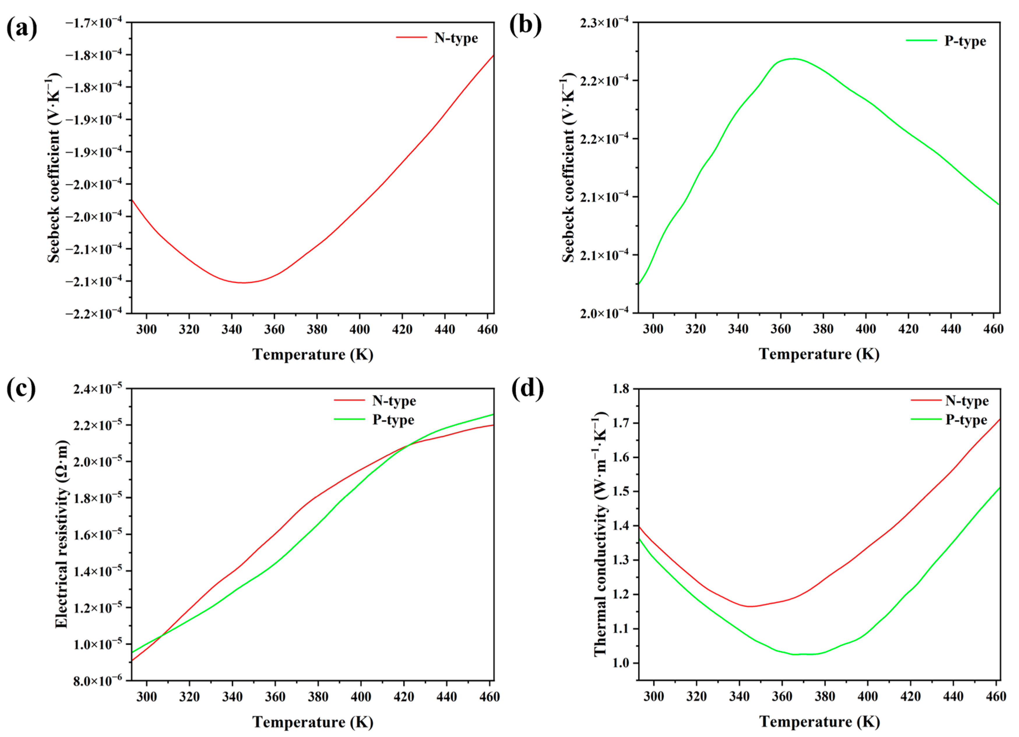
As shown in Figure 1, the size of the copper alloy heat sink is 2000 × 2000 × 400 μm3, and a groove of 1700 × 1700 × 200 μm3 is set in the center of it. In order to support the TE legs and the chip, a heat-insulating XPS block is set in the groove. A pair of TE legs of P-type and N-type with the size of 400 × 200 × 100 μm3 is attached to each side of the heat sink, and the distance of the outer side from the edge line of the groove is 100 μm and the spacing of the two TE legs is 100 μm. The TE legs are connected to each other by a copper slice with a width of 50 μm and a height of 100 μm. Current flows in from the P-type TE leg and out from the N-type TE leg on the same side, making the end that TE legs are connected to the heat sink the hot end, and the other side, which contacts with the chip, the cold end. A SiC chip with dimensions of 1000 × 1000 × 80 μm3 is placed above the TE legs and in the center of the geometry. In addition to this, the physical parameters of the materials used in the thin-film TEC are listed in Table 1, and the physical parameters of the P-type and N-type TE legs as a function of temperature are shown in Figure 2.

2.2. On-Demand Cooling

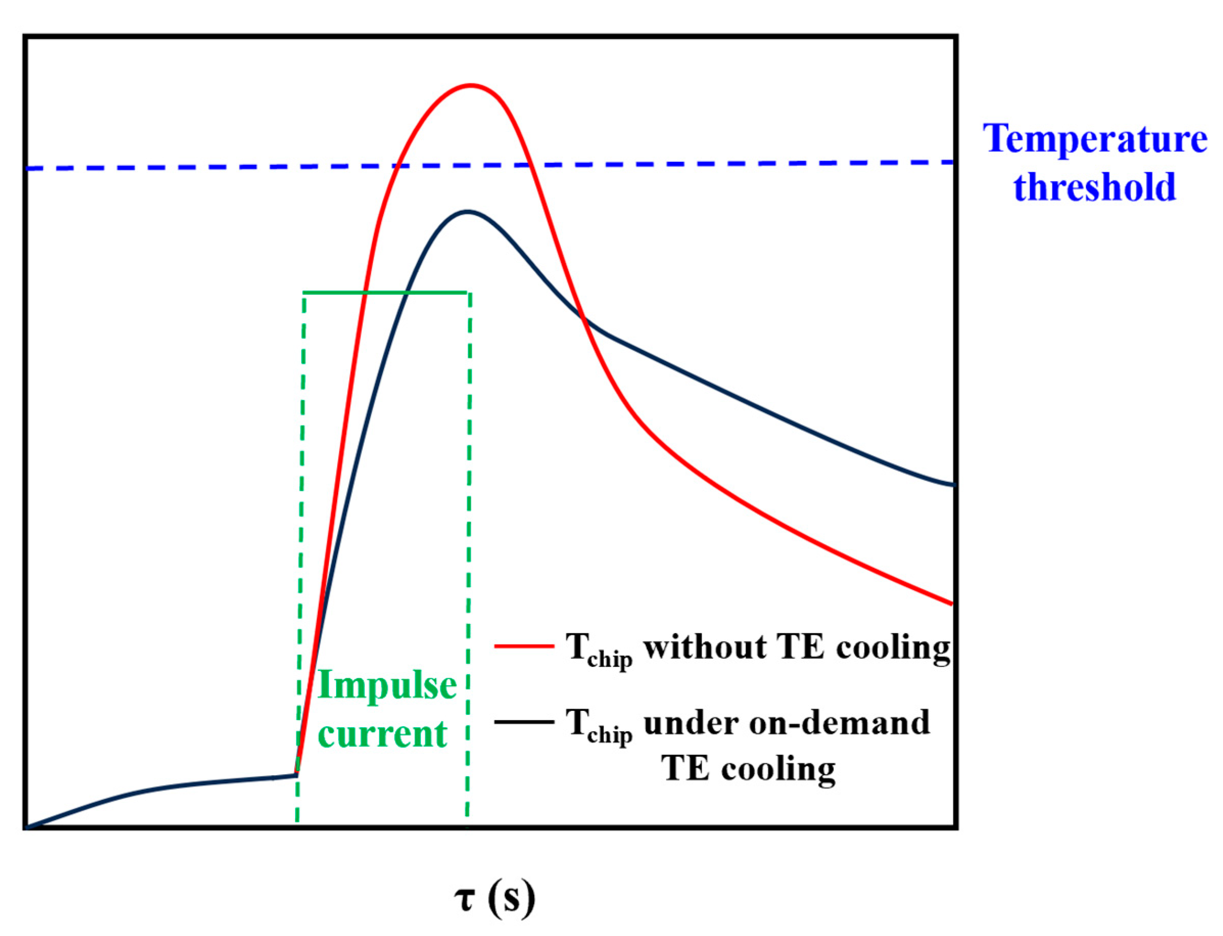
The on-demand transient cooling method is applied to a chip with high impulse heat flux density in a short period of time, whose working stages are designed based on the 5G commercial chip. As shown in Figure 3, in an on-demand cooling system, once there is an impulse heat flux in the chip, the TEC will be triggered to implement transient cooling in order to alleviate the temperature rise of the chip, whose amplitude and duration of the impulse current are adjusted to match the working stage of the chip, thus maximizing the operating frequency of the chip instead of simply restricting the frequency and power of the chip when the temperature is close to the threshold.

2.3. Governing Equations

The thermoelectric cooling process follows the continuity of steady current [35]:
· J = 0
where J represents the current density. It can be obtained by [35]
J = 1 γ ( E α T )
where γ represents the electrical resistivity of the material, α represents the Seebeck coefficient, and E represents the electric field.
The heat flux in the device can be expressed as follows [35]:
q = α T J k T
where the first term of the right side represents Peltier heat, whose direction is from the hot side to the cold side.
The process also follows the law of energy conservation [35]:
q ˙ · q = ρ c p T τ
where q ˙ , ρ , cp, and T τ represent the heat generated per unit volume of thermoelectric material, mass density of the material, specific heat, and rate of change of temperature of the device with time, respectively.
q ˙ can be derived as follows [35]:
q ˙ = E · J = J 2 γ + J α T
Then, the transient energy governing equation for the temperature distribution T of the device under the impose of current J can be derived as follows [35]:
· ( k T ) + γ J 2 T α T J · T = ρ c p T τ
where k, λ, and α are all the functions of the temperature. The first term on the left side represents conductive heat. The second term represents Joule heat within the device. The third term represents Thomson heat. The right side of the equation represents the change rate of the heat absorbed or released by the device.
The governing equations were solved using the ANSYS Workbench 19.2, which transforms these partial differential equations into finite difference equations through the finite element method and gains the solutions under given initial and boundary conditions using an iterative method.

2.4. Boundary Conditions

Given that the heat transfer process of thin-film TEC systems with integrated chips in real situations is complex, the following assumptions were made to simplify calculations:
(1)
All the surfaces were set to be thermally insulated except for the hot and cold sides of the TEC and the bottom face of the heat sink.
(2)
Radiative heat transfer on all surfaces was neglected.
(3)
Parameters of the materials except thermoelectric materials were set not to vary with external factors such as temperature.
(4)
All the materials of the device were isotropic.
(5)
The SiC chip and the surface of the heat sink were electrical-insulating.
In this model, the ambient temperature was set to 298 K, and the temperature of the thin-film TEC was the same as the ambient temperature. According to the actual working condition of the 5G commercial chip, the heat flow density of the chip was divided into 3 stages. The background heat flow density in the time periods of 0–0.4 s and 0.5–1 s was 10,000 W·m−2, and the pulse heat flow density in the time period of 0.4–0.5 s was 300,000 W·m−2. The magnitude of the current imposed on the TE legs was also divided into 3 stages, with no current applied during the 0–0.4 s and 0.5–1 s time periods, and a pulsed current applied during 0.4–0.5 s. The heat was dissipated through water cooling between the bottom surface of the heat sink and the ambient, and the heat convection coefficient was set to the common empirical value of 1000 W·m−2·K−1 [36].

2.5. Numeral Method

In this model, numerical simulations of thin-film TECs were conducted using ANSYS Workbench 19.2 through the finite element method. To validate mesh independence, the size of the TE legs was fixed at 400 × 20 × 10 μm3. The heat flux of the chip was fixed at 10,000 W·m−2 from 0 to 0.4 s and 0.5 to 1 s and at 300,000 W·m−2 from 0.4 to 0.5 s. An impulse current with an amplitude of 0.2 A was imposed during 0.4–0.5 s, while current was absent during the remaining time periods. Three mesh systems with mesh numbers of 18,161, 42,743, and 114,058 were evaluated under identical boundary conditions. The temperature variation of the chip from 0 to 1 s was computed and is presented in Figure 4. The results showed that the error between the peak temperature calculation results for different grid numbers did not exceed 0.5%. It can be considered that the calculation results are independent of the grid. In this study, the system with a grid number of 18,161 was chosen for analysis.

3. Results and Discussions

3.1. Effect of the Amplitude of Impulse Current

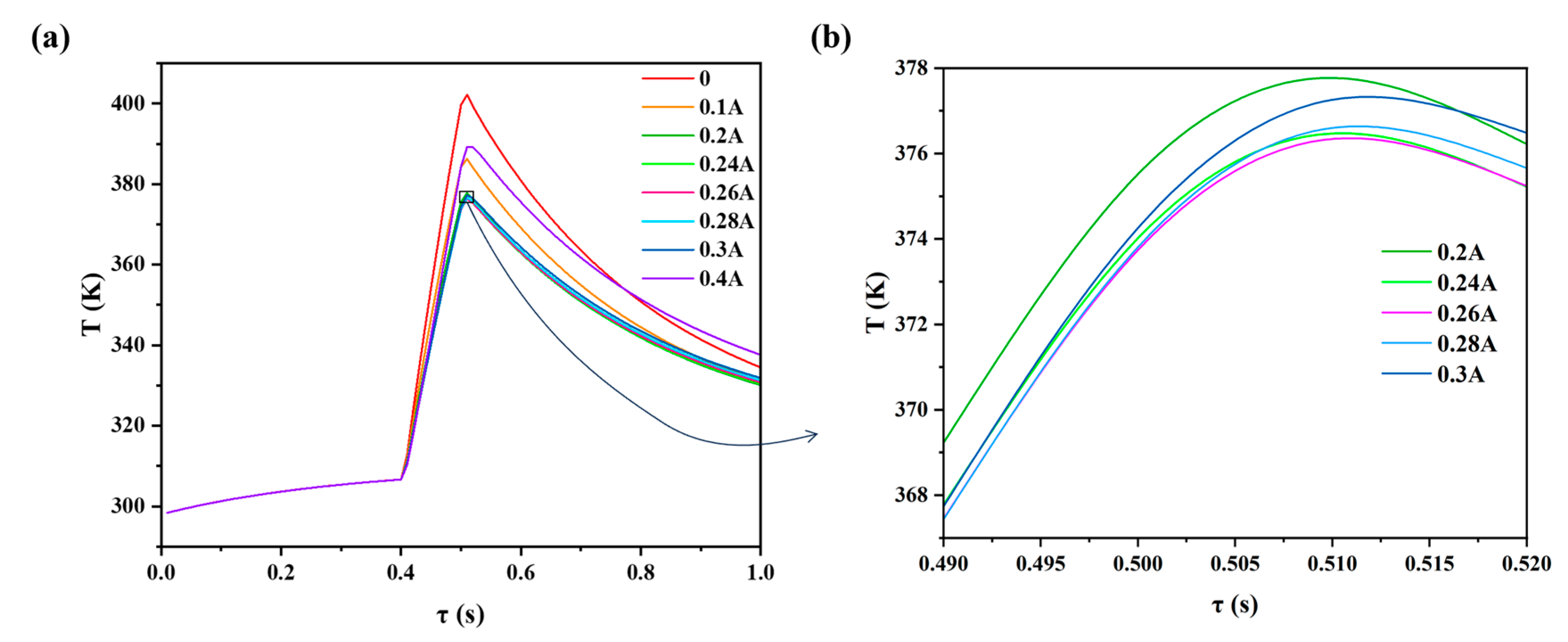
In this section, the impulse heat flux was set to keep constant at 10,000 W·m−2 during 0–0.4 s and 0.5–1 s, and 300,000 W·m−2 during 0.4–0.5 s. Impulse currents of 0, 0.1, 0.2, 0.24, 0.26, 0.28, 0.3, and 0.4 A, respectively, were imposed on the TE leg. Figure 5 illustrates the temperature variations under different impulse currents. When the amplitude of the impulse current was increased from 0 to 0.26 A, the temperature rise rate of the chip gradually slowed down, and the peak temperature also gradually decreased from 402.19 to 376.34 K, achieving an active cooling temperature difference of 25.85 K. When the current was further increased from 0.26 A, the peak temperature of the chip rose instead, and temperature at the end state of t = 1 s also gradually rose. The end-state temperature when the current was 0.4 A was already almost the same as that at no current. This is because when the current is small, the Peltier effect is weak, thus the thermoelectric cooling flux is small. When the current is gradually increased, the thermoelectric cooling capacity gradually increases as well, and the effect of controlling the temperature of the chip is also gradually enhanced. When the current is further increased since Joule heat is quadratically related to current, the Joule heat generated within the TE leg grows rapidly and spreads to the end of the TE leg, offsetting the thermoelectric cooling flux, After the current pulse, the rate of decrease of the chip temperature also gradually slows down compared to that in the absence of current, since the heat accumulated inside the TE leg increases with the pulse current and is later conducted to the end, to the extent that when the amplitude of the current is too high, the final state temperature of the chip is even higher than that in the absence of the current applied.

3.2. Effect of the Length of the Thermoelectric Legs

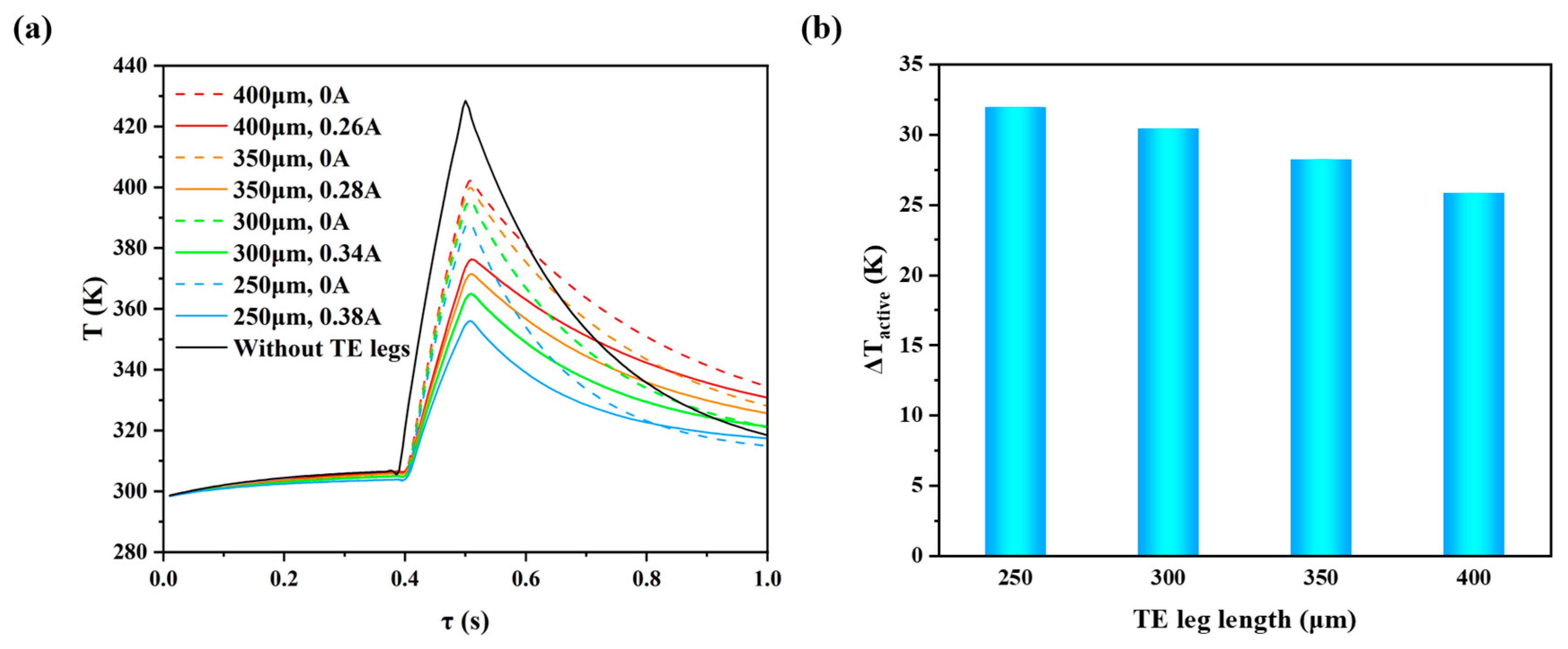
In this section, in order to investigate the effect of the TE leg length on the performance of the device, the width, thickness of the TE legs, and the heat flux of the chip were kept constant at the values mentioned in Section 2.4. First, the case of the chip without the TE leg structure under water cooling was conducted. Then, the TE leg lengths were set at 250, 300, 350, and 400 μm, respectively. Considering that changing the length may result in variations in the heat transfer process, the amplitude of the impulse current will not be set constant. Instead, for each TE leg length, the input pulse current was gradually increased from 0. During the process, the peak temperature of the chip first continued to decrease and then began to increase. Then, the optimal current and the corresponding lowest peak temperature achieved for each device with different TE leg lengths could be determined. Figure 6a demonstrates the temperature variation of passive cooling without current and active cooling under the respective optimal currents for different lengths of TE legs and without the TE leg structure. It can be observed that the cooling performance with the TE leg structure was better than that without the TE leg structure. As is shown, on the one hand, when there was no current imposed, as the length of the TE legs increased, the rate of temperature rise gradually increased during the pulse heat flow on the chip, the peak temperature increased continuously, and after the impulse heat flow, the falling rate of the temperature of the chip decreased. It was found that an increase in the TE leg length is not favorable to the passive heat dissipation of the chip. As the TE leg length increases without changing the material, the overall thermal conductance of the TEC rises, and it is more difficult to dissipate the heat generated in the chip through the TE legs. On the other hand, as the TE leg length increased, the optimum amplitude of the impulse current and the temperature drop of active cooling declined. When the TE leg length increases without changing the material, the overall electrical resistance of the TE leg increases. As a result, the Joule heat generated per unit of current increases and is transferred to the cold end, hindering the thermoelectric cooling effect of the TEC. Therefore, the critical current at which the Joule heating exceeds the increase in thermoelectric cooling gradually decreases, and the corresponding maximum cooling capacity also gradually decreases. It can be concluded that a shorter TE leg length is favorable to better transient cooling performance for the TEC.

3.3. Effect of Imposing Time of the Current

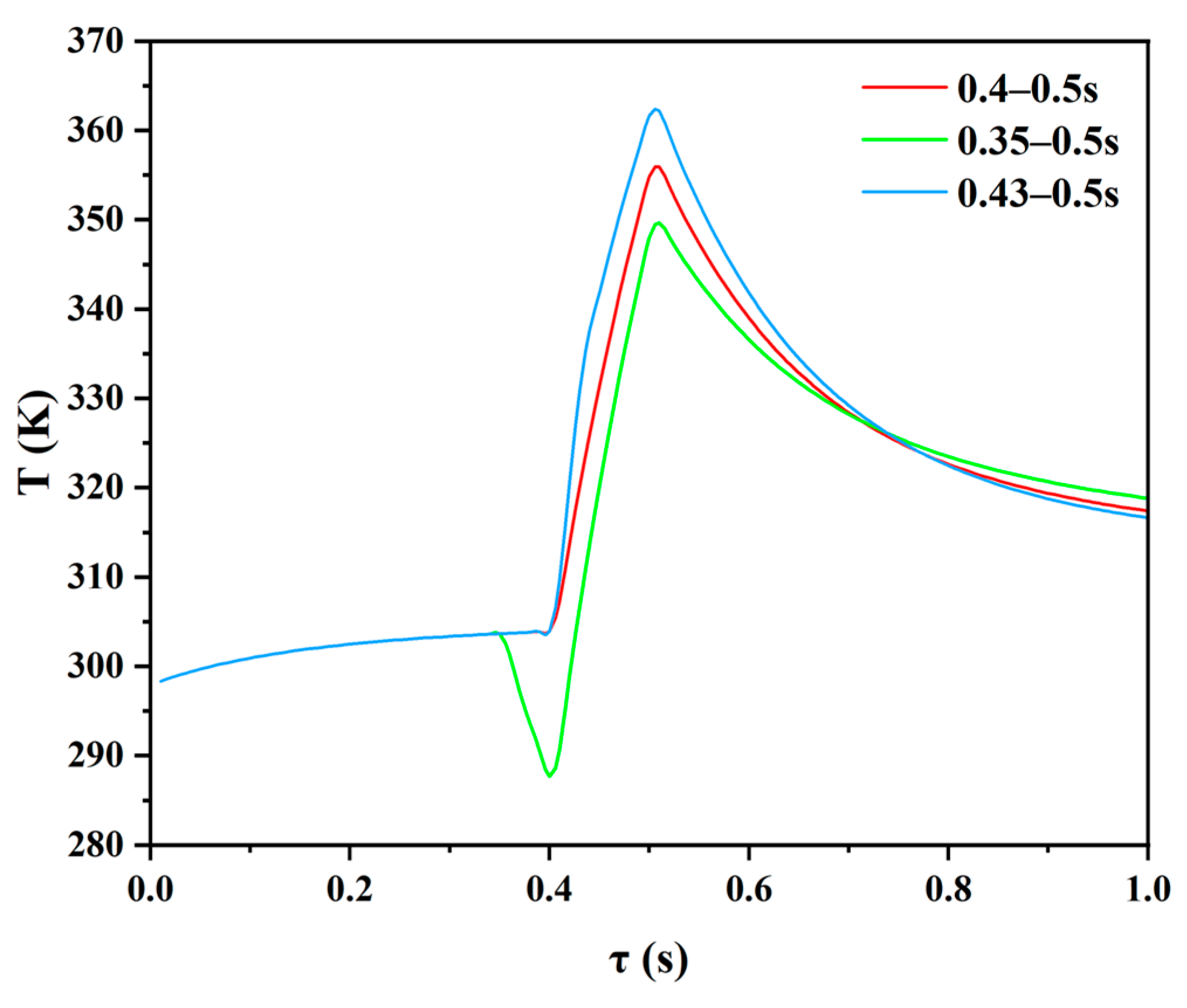
In Section 3.2, the imposing time of the current was fixed at 0.4–0.5 s. But after the impulse current was imposed, there was no temperature rise due to the accumulation of heat from Joule heating and the heat sink flowing back through the TE legs to the chip. Therefore, there are two schemes that can be considered to further reduce the peak temperature of the chip. In one set, aimed at increasing the thermoelectric cooling capacity, the current imposing time was set to 0.35–0.5 s. In other words, the TE cooling was implemented before the impulse heat flow started. In another set, aimed at delaying the diffusion of Joule heat and reducing the heat transferred to the cold end of the TE legs during the time of impulse heat, the impulse current was set at the duration of 0.43–0.5 s. Considering that there is an interaction between the optimal current amplitude and the imposing time, different amplitudes of impulse currents were set at each set of current imposing times until the optimal value corresponding to the lowest peak temperature was found. Figure 7 demonstrates the temperature variation of the chip under the optimum amplitude of the impulse current aforementioned two sets of current imposing times. When the current imposing time was 0.35–0.5 s, the optimal amplitude of the impulse current was still 0.38 A and the peak temperature was 6.25 K lower than that when the current imposing time was 0.4–0.5 s. This is because although the impulse current was imposed prior to the heat flow, making the chip temperature lower than the ambient temperature, and thus heat was transferred from the ambient to the device, plus more Joule heat was generated, the additional cooling effect was still stronger. When the current imposing time was 0.43–0.5 s, the optimum pulse current size was also 0.38 A and the lowest peak temperature achieved was 362.23 K, which was 6.31 K higher compared to that under the current imposing time of 0.4–0.5 s. When the amplitude of the impulse current was increased to 0.4 A, the temperature of the chip was slightly lower than that under the amplitude of 0.38 A. However, from 0.5 s on, the temperature of the chip was higher than that under the amplitude of 0.38 A. This is due to the small size of the thin-film TEC, thus the thermal inertia is small, and the Joule heat generated from the TE legs is easy to transfer to the end, so that even if the pulse current increased slightly, during a short period of time, the increase in the Joule heat diffused to the end was larger than the increase in thermoelectric cooling capacity. It can be deduced that the cooling performance cannot be improved by continuing to increase the amplitude of the current. In summary, it can be concluded that imposing the impulse current appropriately earlier than the impulse heat flow is beneficial to further reduce the peak temperature of the chip.

3.4. Effect of Contact Thermal Resistance

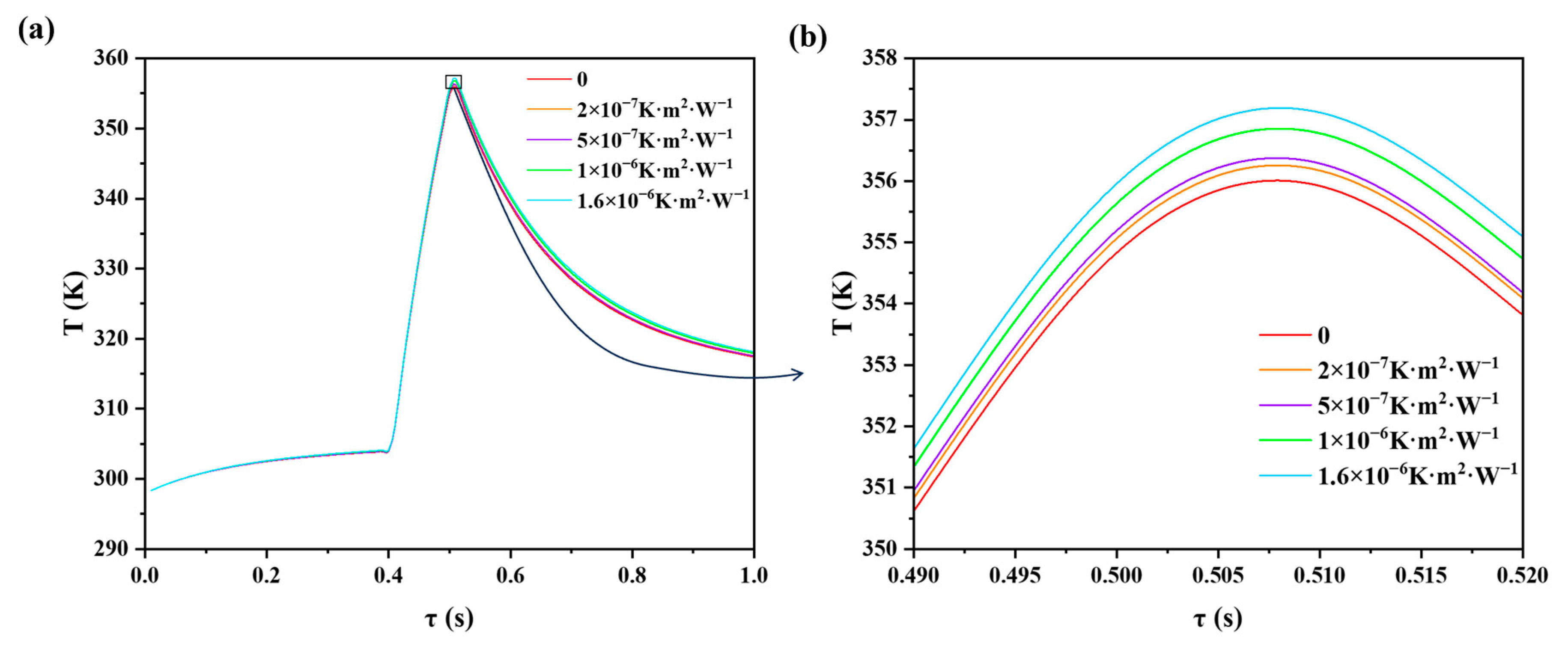
According to the interfacial phonon scattering theory proposed by Yang et al. [37], the contact thermal resistance of an ideal interface is 10−9 to 10−8 K·m2·W−1. Previous studies have found that contact thermal resistance has a more significant effect on thin-film TECs than contact electrical resistance does [38]. In this section, the size of the TE legs was fixed at 250 × 20 × 10 μm3. The heat flux of the chip was fixed at 10,000 W·m−2 during 0 and 0.4 s and 0.5 and 1 s, and at 300,000 W·m−2 during 0.4 and 0.5 s. The amplitude of the impulse current was fixed at the optimal value in Section 3.2, i.e., 0.38 A during 0.4–0.5 s and no current for the rest of the time. The contact thermal resistance was set at 0, 2 × 10⁻⁷, 5 × 10⁻⁷, 1 × 10⁻⁶, and 1.6 × 10⁻⁶ W·m2·K−1, respectively. Figure 8 illustrates the temperature variations under different contact thermal resistances. It can be observed that when the contact thermal resistance was gradually increased from 0 to 1.6 × 10⁻⁶ W·m2·K−1, the peak temperature of the chip rose from 355.92 to 357.12 K accordingly. The peak temperature of the chip increased by only 1.2 K compared to that without contact thermal resistance. In the traditional-structure TEC proposed by Wu et al. [35], when the contact thermal resistance increased from 8 × 10⁻⁸ W·m2·K−1 to 1.42 × 10⁻⁶ W·m2·K−1, the peak temperature of the chip increased by 7 K. Since the contact area of the thin-film thermoelectric cooler with a horizontal structure is significantly smaller, the total thermal resistance of the device is not too large, and the effect on the cooling performance of the device is limited.

4. Conclusions

In this paper, a thin-film TEC with a compact horizontal structure was proposed to address the heat dissipation problem of electronic devices with high heat flow density and high integration. The on-demand transient cooling method was applied to a chip with high heat flux density in a short period of time to control its temperature rise. A multi-physics field model of thermoelectric transient cooling was established to explore the effects of the magnitude of the impulse current, the TE leg length, the current imposing time, and the size of contact thermal resistance, etc., in detail. And the conclusions were as follows:
(1)
When the amplitude of the impulse current was gradually increased from 0 to 0.38 A, the cooling performance of the TEC was gradually enhanced, and a temperature drop of up to 25.85 K could be achieved, which contributed to keeping the chip running stably and efficiently. However, when the amplitude of the impulse current exceeded 0.26 A and continued to increase, the transient cooling performance decreased instead. When the amplitude was too large, the final temperature was even higher than that when the current was absent.
(2)
When the TE leg length was increased from 250 to 400 μm, the peak temperature under passive cooling gradually increased from 387.83 to 402.19 K, and the temperature drop of active cooling decreased from 31.91 to 25.85 K. The increase in the length of the TE legs was detrimental to both passive and active cooling.
(3)
Extending the current imposing time appropriately was conducive to further reducing the peak temperature of the chip while increasing the amplitude of the impulse current and delaying the current imposing time was unfeasible.
(4)
When contact thermal resistance was increased from 0 to 1.6 × 10⁻⁶ W·m2·K−1, the peak temperature increased by only 1.2 K. The contact thermal resistance had a small effect on the transient cooling performance of the TEC if the contact thermal resistance was less than 1.6 × 10⁻⁶ W·m2·K−1.
In the next step, we will focus on the fabrication of the TEC structure and experiment to validate the result.

Author Contributions

Conceptualization, Y.W.; methodology, T.M.; validation, L.L.; formal analysis, L.L.; investigation, L.L.; resources, T.M.; data curation, P.Z.; writing—original draft, L.L.; writing—review & editing, T.M. and Y.W.; supervision, Y.W.; project administration, P.Z. and Y.Y. All authors have read and agreed to the published version of the manuscript.

Funding

This research was supported by the National Natural Science Foundation of China (Grant No. 52208124), Hubei Provincial Key Research and Design Project (Grant No. 2020BAB129), and the Scientific Research Foundation of Wuhan University of Technology (Grant No. 40120237 and 40120551).

Data Availability Statement

Data are contained within the article.

Conflicts of Interest

The authors declare no conflict of interest.
Nomenclatures

Nomenclatures

Symbols
cpSpecific heat (J·kg−1·K−1)
E Electric field intensity (V·m−1)
j Current density (A∙m−2)
kThermal conductivity of the thermoelectric material (W∙m−1∙K−1)
q Heat flux density (W·m−2)
q ˙ Intensity of the internal heat source (W·m−3)
RElectrical resistance of the thin-film TEC (Ω)
TTemperature (K)
Δ T Temperature difference (K)
ΔTactiveThe temperature drop of active cooling (K)
T Temperature gradient (K∙m−1)
αSeebeck coefficient (V∙K−1)
ρ Mass density (kg·m−3)
γ Electrical resistivity of the thermoelectric material (Ω∙m)
Abbreviations
TEThermoelectric
TECThermoelectric cooler
ZTFigure of merit

References

  1. Xiu, L. Time Moore: Exploiting Moore’s Law From The Perspective of Time. IEEE Solid-State Circuits Mag. 2019, 11, 39–55. [Google Scholar] [CrossRef]
  2. Ming, T.; Chen, S.; Yan, Y.; Gong, T.; Wan, J.; Wu, Y. The simulated cooling performance of a thin-film thermoelectric cooler with coupled-thermoelements connected in parallel. Heliyon 2022, 8, e10025. [Google Scholar] [CrossRef] [PubMed]
  3. Xie, J.L.; Tan, Y.B.; Wong, T.N.; Duan, F.; Toh, K.C.; Choo, K.F.; Chan, P.K.; Chua, Y.S. Multi-nozzle array spray cooling for large area high power devices in a closed loop system. Int. J. Heat Mass Transf. 2014, 78, 1177–1186. [Google Scholar] [CrossRef]
  4. Zhang, N.; Jiao, B.; Ye, Y.; Kong, Y.; Du, X.; Liu, R.; Cong, B.; Yu, L.; Jia, S.; Jia, K. Embedded cooling method with configurability and replaceability for multi-chip electronic devices. Energy Convers. Manag. 2022, 253, 115124. [Google Scholar] [CrossRef]
  5. Xiong, K.; Meng, L.; Wang, S. Design, fabrication, investigation and analysis of a novel flat evaporator loop heat pipe for cooling high heat flux server chips. Appl. Therm. Eng. 2022, 201, 117775. [Google Scholar] [CrossRef]
  6. Wang, P.; Bar-Cohen, A. On-chip hot spot cooling using silicon thermoelectric microcoolers. J. Appl. Phys. 2007, 102, 034503. [Google Scholar] [CrossRef]
  7. Nandihalli, N. Thermoelectric films and periodic structures and spin Seebeck effect systems: Facets of performance optimization. Mater. Today Energy 2022, 25, 100965. [Google Scholar] [CrossRef]
  8. Chen, X.; Dai, W.; Wu, T.; Luo, W.; Yang, J.; Jiang, W.; Wang, L. Thin Film Thermoelectric Materials: Classification, Characterization, and Potential for Wearable Applications. Coatings 2018, 8, 244. [Google Scholar] [CrossRef]
  9. Chen, W.; Shi, X.; Zou, J.; Chen, Z. Thermoelectric coolers for on-chip thermal management: Materials, design, and optimization. Mater. Sci. Eng. R Rep. 2022, 151, 100700. [Google Scholar] [CrossRef]
  10. Ding, J.; Zhao, W.; Jin, W.; Di, C.; Zhu, D. Advanced Thermoelectric Materials for Flexible Cooling Application. Adv. Funct. Mater. 2021, 31, 2010695. [Google Scholar] [CrossRef]
  11. Rao, A.; Ji, X.; Tritt, M. Properties of nanostructured one-dimensional and composite thermoelectric materials. MRS Bull. 2006, 31, 218–223. [Google Scholar] [CrossRef]
  12. Mao, J.; Chen, G.; Ren, Z. Thermoelectric cooling materials. Nat. Mater. 2020, 20, 454–461. [Google Scholar] [CrossRef] [PubMed]
  13. Venkatasubramanian, R.; Siivola, E.; Colpitts, T.; O’Quinn, B. Thin-film thermoelectric devices with high room-temperature figures of merit. Nature 2001, 413, 597–602. [Google Scholar] [CrossRef] [PubMed]
  14. Manno, M.V. On-Chip Thermoelectric Hotspot Cooling. Ph.D. Thesis, University of Maryland, College Park, MD, USA, 2015. [Google Scholar]
  15. Zhu, W.; Deng, Y.; Wang, Y.; Wang, A. Finite element analysis of miniature thermoelectric coolers with high cooling performance and short response time. Microelectron. J. 2013, 44, 860–868. [Google Scholar] [CrossRef]
  16. Lara Ramos, D.; Barati, V.; Garcia, J.; Reith, H.; Li, G.; Pérez, N.; Schierning, G.; Nielsch, K. Design Guidelines for Micro-Thermoelectric Devices by Finite Element Analysis. Adv. Sustain. Syst. 2019, 3, 1800093. [Google Scholar] [CrossRef]
  17. Alexandrov, B.; Sullivan, O.; Song, W.J.; Yalamanchili, S.; Kumar, S.; Mukhopadhyay, S. Control Principles and On-Chip Circuits for Active Cooling Using Integrated Superlattice-Based Thin-Film Thermoelectric Devices. IEEE Trans. Very Large Scale Integr. (VLSI) Syst. 2014, 22, 1909–1919. [Google Scholar] [CrossRef]
  18. Gao, Y.; Shi, C.; Wang, X. Numerical analysis for transient supercooling effect of pulse current shapes on a two-stage thermoelectric cooler. Appl. Therm. Eng. 2019, 163, 114416. [Google Scholar] [CrossRef]
  19. Wu, Y.; Yang, J.; Chen, S.; Zuo, L. Thermo-element geometry optimization for high thermoelectric efficiency. Energy 2018, 147, 672–680. [Google Scholar] [CrossRef]
  20. Zhou, Q.; Bian, Z.; Shakouri, A. Pulsed cooling of inhomogeneous thermoelectric materials. J. Phys. D Appl. Phys. 2007, 40, 4376–4381. [Google Scholar] [CrossRef]
  21. Snyder, G.J.; Fleurial, J.P.; Caillat, T.; Yang, R.; Chen, G. Supercooling of Peltier cooler using a current pulse. J. Appl. Phys. 2002, 92, 1564–1569. [Google Scholar] [CrossRef]
  22. Yang, R.; Chen, G.; Ravi Kumar, A.; Snyder, G.J.; Fleurial, J.-P. Transient cooling of thermoelectric coolers and its applications for microdevices. Energy Convers. Manag. 2005, 46, 1407–1421. [Google Scholar] [CrossRef]
  23. Hao, J.; Qiu, H.; Ren, J.; Ge, Z.; Chen, Q.; Du, X. Multi-parameters analysis and optimization of a typical thermoelectric cooler based on the dimensional analysis and experimental validation. Energy 2020, 205, 118043. [Google Scholar] [CrossRef]
  24. Wang, T.; Wu, H.; Gao, D.; Zhang, K.; Meng, J. Achieving Better Super-cooling in a Two-Stage Transient Thermoelectric Device with Constraint-Free Pulse Current by Multi-Objective Optimization. J. Therm. Sci. 2021, 30, 1349–1362. [Google Scholar] [CrossRef]
  25. Liu, D.; Cai, Y.; Zhao, F.-Y. Optimal design of thermoelectric cooling system integrated heat pipes for electric devices. Energy 2017, 128, 403–413. [Google Scholar] [CrossRef]
  26. Jeong, E.S. A new approach to optimize thermoelectric cooling modules. Cryogenics 2014, 59, 38–43. [Google Scholar] [CrossRef]
  27. Qiu, C.; Shi, W. Comprehensive modeling for optimized design of a thermoelectric cooler with non-constant cross-section: Theoretical considerations. Appl. Therm. Eng. 2020, 176, 115384. [Google Scholar] [CrossRef]
  28. Nimmagadda, L.A.; Sinha, S. Thermoelectric Property Requirements for On-Chip Cooling of Device Transients. IEEE Trans. Electron Devices 2020, 67, 3716–3721. [Google Scholar] [CrossRef]
  29. Watzman, S.J.; Duine, R.A.; Tserkovnyak, Y.; Boona, S.R.; Jin, H.; Prakash, A.; Zheng, Y.; Heremans, J.P. Magnon-drag thermopower and Nernst coefficient in Fe, Co, and Ni. Phys. Rev. B 2016, 94, 144407. [Google Scholar] [CrossRef]
  30. Adams, M.J.; Verosky, M.; Zebarjadi, M.; Heremans, J.P. Active Peltier Coolers Based on Correlated and Magnon-Drag Metals. Phys. Rev. Appl. 2019, 11, 054008. [Google Scholar] [CrossRef]
  31. Rowe, D.; Kuznetzov, Z.; Kuznetsova, L.; Min, G. Electrical and thermal transport properties of intermediate-valence YbAl3. J. Phys. D Appl. Phys. 2002, 35, 2183–2186. [Google Scholar] [CrossRef]
  32. Ren, Z.; Kim, J.C.; Lee, J. Transient Cooling and Heating Effects in Holey Silicon-Based Lateral Thermoelectric Devices for Hot Spot Thermal Management. IEEE Trans. Compon. Packag. Manuf. Technol. 2021, 11, 1214–1222. [Google Scholar] [CrossRef]
  33. Sun, D.; Shen, L.; Sun, M.; Yao, Y.; Chen, H.; Jin, S. An effective method of evaluating the device-level thermophysical properties and performance of micro-thermoelectric coolers. Appl. Energy 2018, 219, 93–104. [Google Scholar] [CrossRef]
  34. Gong, T.; Gao, L.; Wu, Y.; Tan, H.; Qin, F.; Xin, X.; Shen, L.; Li, J.; Ming, T. A Model to Evaluate the Device-Level Performance of Thermoelectric Cooler with Thomson Effect Considered. J. Therm. Sci. 2022, 31, 712–726. [Google Scholar] [CrossRef]
  35. Wu, Y.; Chen, S.; Gong, T.; Shi, T.; Zuo, L.; Yan, Y.; Fang, Y.; Ming, T. A Strategy to Reduce the Peak Temperature of the Chip Working under Dynamic Power Using the Transient Cooling Effect of the Thin-Film Thermoelectric Cooler. J. Therm. Sci. 2022, 31, 1094–1105. [Google Scholar] [CrossRef]
  36. Rohsenow, W.M.; Hartnett, J.P.; Cho, Y.I. (Eds.) . Handbook of Heat Transfer; Osborne McGraw-Hill: New York, NY, USA, 1973. [Google Scholar]
  37. Chen, G. Nanoscale Energy Transport and Conversion: A Parallel Treatment of Electrons, Molecules, Phonons, and Photons; Oxford University Press: Oxford, UK, 2005. [Google Scholar]
  38. Xu, G.; Duan, Y.; Chen, X.; Ming, T.; Huang, X. Influence of interface contact effects on performance of different scale thermoelectric coolers. Appl. Therm. Eng. 2020, 169, 114933. [Google Scholar] [CrossRef]
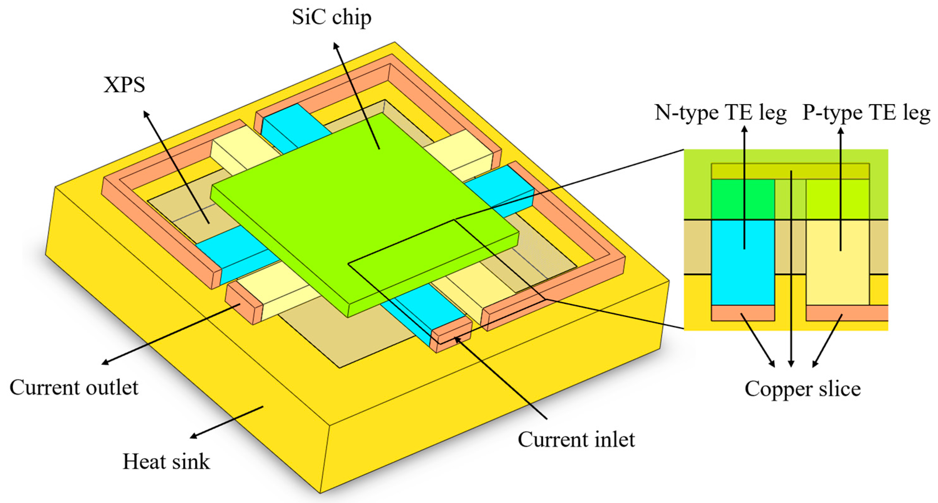
Figure 1. The 3D diagram of the thin-film thermoelectric cooler.
Energies 16 08109 g001
Figure 2. Temperature-dependent properties of the P-type and N-type TE legs; (a,b) Seebeck coefficient, (c) electrical resistivity, (d) thermal conductivity.
Energies 16 08109 g002
Figure 3. The schematic diagram of on-demand cooling.
Energies 16 08109 g003
Figure 4. Temperature profiles under different grid systems.
Energies 16 08109 g004
Figure 5. (a) Temperature profiles of the TEC under different impulse currents; (b) local magnification of (a).
Energies 16 08109 g005
Figure 6. (a) Temperature profiles of TECs with TE legs of different lengths under passive cooling and respective optimum current and that without TE leg structure, (b) temperature drops of active cooling.
Energies 16 08109 g006
Figure 7. Temperature profiles under different current imposition times.
Energies 16 08109 g007
Figure 8. (a) Temperature profiles with different contact thermal resistances, (b) local magnification of (a).
Energies 16 08109 g008
Table 1. Properties of the materials in the model.
MaterialThermal Conductivity
(W·m−1·K−1)
Electrical Resistivity (Ω·m)Specific Heat
(J·kg−1·K−1)
Cu3981.8 × 10−7390
SiC450-1200
Cu alloy401-398
Disclaimer/Publisher’s Note: The statements, opinions and data contained in all publications are solely those of the individual author(s) and contributor(s) and not of MDPI and/or the editor(s). MDPI and/or the editor(s) disclaim responsibility for any injury to people or property resulting from any ideas, methods, instructions or products referred to in the content.