Abstract
This paper proposes a novel lamilloy cooling structure equipped with internal minichannels used in a combustor flame cylinder. The overall flow and heat transfer characteristics of three different internal minichannel configurations (parallel-flow, counter-flow, and staggered arrangements. PF, CF, and SF for short) are analyzed and compared. From the analysis of the heat transfer characteristic, it is found that the CF structure possesses the best cooling effect and temperature uniformity. The average cooling effectiveness (ηave) of the CF structure increased by 20.6% and 20.4%, and the average temperature gradient () decreased by 76.9% and 32.8%, compared with the SF structure and PF structure, respectively. From the analysis of flow characteristics, the coolant ejected from the minichannel one region of the SF structure completely blocks the direct contact between the mainstream and the lamilloy, while transferring more from the mainstream to the minichannel two region. Different from the SF structure, film cooling at the two outlet of the CF structure transfers most of the mainstream to the lower position, which further improves the cooling effect of the two internal minichannels.
1. Introduction
To improve the gas turbine cycle efficiency for an advanced gas turbine, the combustion chamber outlet temperature must increase. The combustor flame cylinder wall is the part with the highest working temperature and the shortest service life, due to the direct erosion of high temperature radiation and high temperature gas. The life and reliability of the combustor depends on the temperature and its uniformity with the wall of the flame cylinder. At the same time, to meet the requirements of low emissions, the available coolant gas is reduced, which makes the cooling problem more acute. Therefore, flame tube cooling technology has become an important part of combustor design.
Film cooling is a traditional cooling method. Its research started earlier, and has the advantages of high efficiency and reliability. It is still widely used in the cooling of combustors and high temperature components [1]. Gustafsson and Johansson [2] studied film cooling under combustion chamber conditions by experiment. Their results showed that increasing the number of film holes or decreasing the inclination angle will lead to an increase in cooling effectiveness (). Wang et al. [3] studied the impact of different inclination angles of film holes, including () on the η, used in combustor liner. They observed that the maximum η was achieved when is 30°, which was 10.4% higher than that with 90°. Bunker [4] studied the cooling structure of shaped holes and proposed an expanded film hole structure to improve the cooling effect. They found that the film effectiveness within the range of increased from 50 to 75%. Vishal et al. [5] proposed a new film holes arrangement, wherein hole diameter is variable when used in combustor liner. They observed that coolant consumption can be reduced by 13.85% while maintaining a similar η. Kusterer et al. [6] introduced a double-jet film cooling configuration to prevent the kidney vortices from rising. The numerical results verified that the generated anti-kidney vortices can improve the cooling effect. Zhou et al. [7] studied three different hole structures under three blowing ratios. Their findings suggest that the console hole possessed the best cooling effect. Kiyici et al. [8] studied six different slot geometries used in combustor liner; the maximum η was obtained when flat lip geometry with 10 mm height was applied. Lee et al. [9] explored the impact of shaped holes on film cooling effect. The results showed that the η can be increased by 55%, compared with the round hole. However, the disadvantage of film cooling is that the cooling form is single, the cooling efficiency is low, and the demand for cooling air consumption is large. At the same time, the wall surface of the flame cylinder is not evenly cooled along the axial direction, which forms a large temperature gradient in the flame cylinder, resulting in large thermal stress and low cycle fatigue failure.
Nowadays, the combustor flame tube has developed from pure film cooling to lamilloy cooling. Zhang et al. [10] proposed a new lamilloy cooling configuration by shortening the film outlet spacing and applying inclined film holes. The results indicated that the η increased by 16.2%, while decreasing the friction coefficient (). Liu et al. [11] designed a triple-stage impingement cooling structure to improve the temperature uniformity, and they observed that the gas consumption was reduced by 50% when ensuring the same η. Yoko et al. [12] applied the multi-fidelity method to design a liner lamilloy cooling structure, combining impingement and effusion technology. This analysis methodology was proved to predict the temperature distribution. Zhang et al. [13] compared the impact of different pin–fin structures on the flow and cooling effects in a lamilloy arrangement. The results showed that square pin–fins possessed the optimal cooling effect. Liu et al. [14] designed two novel film hole shapes, with compound angles used in a double-layer lamilloy structure. They found that the η can be increased by 15%. Zhang et al. [15] replaced a round hole with an expanding-shape hole used in a lamilloy structure, which combined an impingement hole, a film hole, and a pin-fin. The results showed that the η can be increased by 24%.
The internal minichannels (MCs) are widely used in the cooling of electronic chips, due to their excellent heat transfer characteristic [16]. Deng et al. [17] designed a combustor by introducing an internal minichannel to achieve a high cooling effect. They found that an 80% maximum wall temperature reduction was necessary. Chen et al. [18] studied and compared the minichannel structure when equipping the triangular prism as pin-fins. They observed that a backward structure obtained the best temperature uniformity, with the largest Nusselt number () and the highest . Moradikazerouni et al. [19] compared the cooling performance under five different minichannel shapes. They believed that a hexagonal channel had the lowest , while a triangular shape had the best cooling effect. You et al. [20] executed an optimization process on the heat generation and the volume ratio when considering non-uniform heat generation, and then acquired optimal geometries under different heat generation conditions. Osman et al. [21] compared flow and cooling performances for three kinds of channel structures. They observed that serpentine channels had the optimal cooling effect, while having the biggest pressure loss. Kanargi et al. [22] explored the flow and cooling performances of cooling channels equipped with oblique-fins. The results indicated that a 30° oblique-fin can produce higher, more secondary flow rates, improving the cooling effect when compared to the 45° counterpart. Radwan and Ahmed [23] proposed novel cooling MCs using different configurations, and studied different flow direction and a different channel layer. They observed that parallel flow channel configuration obtained the best cooling effect. Chiu et al. [24] explored the impacts of channel geometry and pressure drop on the cooling performance. They reported that the local decreases with an increasing aspect ratio. The feature of internal MCs, discussed above, is that the inlet and outlet are parallel to the MCs, whereas, in the combustor application, the inlet and outlet are on both sides of the wall of the flame cylinder, so the inlet and outlet are arranged vertically with the internal MCs. At the same time, applying phase change material is also a hot spot to improve the performance of heat transfers [25].
The related studies, mentioned above, suggest that lamilloy structure has excellent cooling performance. However, for the lamilloy structures described above, the internal channels are connected as a whole, so the coolant cannot be evenly distributed in each position of the lamilloy.
Our research group has designed an innovative lamilloy cooling structure with two separate, staggered, internal MCs [26]. Earlier research results revealed that the average η can be improved by four times, under the same coolant consumption. However, the different MC configurations have not been studied. The scope of this work is to explore the influence of two MC configurations on cooling performance of the lamilloy structure. Herein, a lamilloy cooling structure is put forward according to the practical working condition of a gas turbine combustor, and different MC configurations are studied and compared, including staggered structure, parallel-flow, and counter-flow structure. To show the comprehensive analysis of lamilloy structure, the temperature and its uniformity distributions within the lamilloy lower surface are analyzed in detail. In addition, a detailed flow analysis is carried out, and different sections are selected to obtain the flow characteristic. Furthermore, the flow and heat transfer mechanisms of internal MCs are revealed, providing a theoretical basis for the cooling of the combustor flame tube with lamilloy structure. To summarize, this research brings a new exploration for the novel lamilloy cooling structure, and also provides a research method for the design of new cooling structures.
2. Numerical Methods and Validation
2.1. Physical Model
Figure 1a shows the computational domains, which mainly include the mainstream chamber, the solid domain, the internal minichannels, and the coolant chamber. In this work, the combustor flame tube is equivalent to a flat plate, and two internal minichannels (MCs) are selected as research objects, due to the periodicity. The staggered-flow structure (SF) includes two staggered channels (shown in Figure 1b): the parallel-flow structure (PF), which combines two parallel channels, and the counter-flow structure (CF), which combines two counter channels, respectively (as shown in Figure 1c,d). Namely, two coolant flow directions are investigated in this work. For counter-flow channels, there are three main cooling effects. The coolant first conducts an impingement cooling, and then the coolant performs convective heat transfer with the wall. Finally, it conducts film cooling. For parallel-flow channels, only the first two cooling configurations are present.
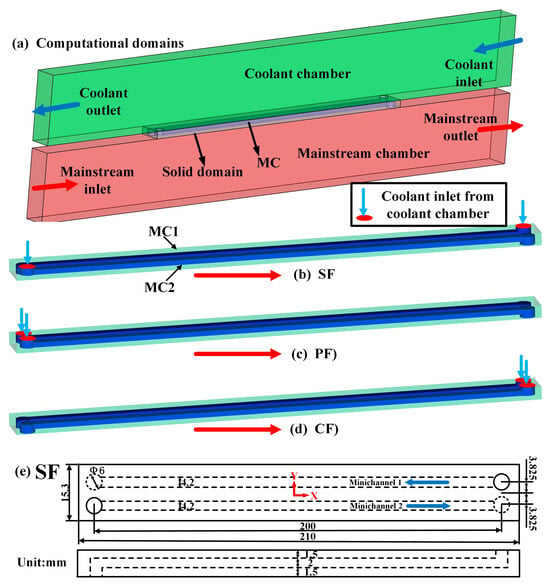
Figure 1.
Schematic diagrams of the different designed MCs structures: (a) computational domains, (b) staggered flow (SF), (c) parallel flow with the mainstream (PF), (d) counter flow with the mainstream (CF), (e) detailed dimensions of the MCs.
The geometric dimensions are shown in Figure 1e. The three structures have the same overall dimensions, and the only difference is the direction of the configured MCs. As well, two MCs are arranged for each structure. Take the SF structure, for example: the lamilloy is defined with the length = 210 mm, the width = 15.3 mm, and the height = 5 mm. The inlet and outlet of the minichannel is a cylinder of diameter = 6 mm. The length, width, and height of the MCs are 200 mm, 4.2 mm, and 2 mm, respectively. The size of the lamilloy structure used in this paper meets the size of the actual combustor flame tube; this allows for a more detailed study of the flow and heat transfer characteristics of the real combustor flame tube.
2.2. Computational Domain and Boundary Conditions
To ensure grid quality and computational accuracy, both hexahedral and tetrahedral grids are used. Figure 2 shows the computational meshes used in this study, which are generated by ANSYS ICEM 17.0. To solve the flow parameters of the viscous sublayer, the height of the first layer elements near the wall is set as 0.0001 mm to ensure y+ is less than 1. As only two MCs are selected, the spanwise is set periodically. The dimensions of the coolant and mainstream chamber are both 400 mm × 15.3 mm × 48 mm. The coolant chamber and mainstream chamber are both 400 mm in length, the solid zone is 210 mm in length, and the two extended 95 mm fluid domains are in place to stabilize the inlet and outlet flow, which do not participate in heat transfer.
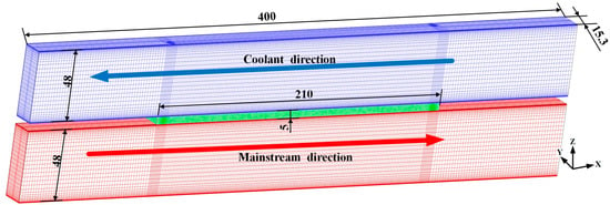
Figure 2.
The computational meshes adopted in the numerical simulation.
The 3D compressible and viscous steady Reynolds Averaged Navier-Stokes (RANS) equations are solved using ANSYS CFX17.0. The diffusion terms, source terms, and convection terms in the equation are discretized with a second-order format discretization scheme. The mass, momentum, and energy conservation equations are solved for the gas flow, and only the heat conduction equation is solved in the solid domain. The overall residual level of the numerical simulation is set to .
The lamilloy structure in this work is applied to the combustor flame tube, so the practical working condition is used. The boundary condition adopted herein is defined as follows.
The inlet of the coolant chamber is set as: static temperature is 740 K, and the inlet velocity is 5 m/s. The outlet of the coolant chamber is set as: average static pressure is 2.3 MPa. The inlet of the mainstream chamber is set as: static temperature is 1795 K, and the inlet velocity is 75 m/s. The outlet of the mainstream chamber is set as: average static pressure is 2.1965 MPa, as shown in Table 1.

Table 1.
Boundary conditions.
The upper wall of the solid (which contacts with the coolant chamber), the lower wall of the solid (which contacts with the mainstream chamber), as well as the walls of the internal MCs (which contact with the internal MCs) are set as the fluid-solid coupling interfaces, where the heat flux and temperature of fluid and solid domains are conservative. Additionally, the six walls perpendicular to the direction are set as the periodic boundaries.
The density and specific heat of 314 stainless steel is assumed constant at 7854 kg/, and 434 J/(kg·K), respectively. The thermal conductivity is determined by,
where and are the thermal conductivity and temperature of the 314 stainless steel, respectively.
The physical property parameters of ideal gas are modified to obtain more accurate results; the density and thermal conductivity of air depending on temperature are obtained using the property table [27]; the dynamic viscosity of air is determined by the Sutherland law [28]; the specific heat capacity is obtained by linear fitting formula.
where is the temperature of air, ρ and are the density and thermal conductivity of air, is the dynamic viscosity, is the specific heat capacity, and Pa·s, , and = 110.4 K.
2.3. Turbulence Model Validation
In order to select the appropriate turbulence model, the comparison between simulation and experimental results is essential. Figure 3a shows the comparison of numerical results obtained from different turbulent models and experimental data from Liu et al. [14]. Both SST and turbulence models can reflect the distribution trend of (line-averaged η), but compared with the turbulence model, SST is more consistent with the experimental results. The RNG turbulence model shows the poorest agreement, with the largest deviation. Therefore, the SST turbulence model is used in this work. Moreover, the SST turbulence model is widely used to calculate the flow and heat transfer characteristics in MCs [29,30].
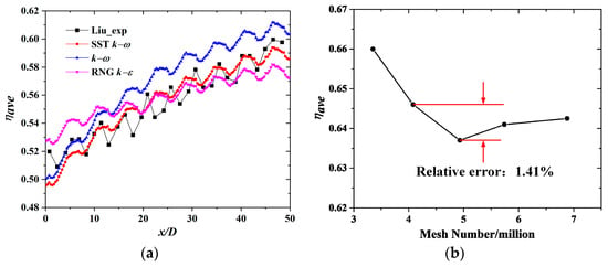
Figure 3.
Turbulence Model Validation calculation. (a) Comparison of the ηave, (b) grid independence calculation.
The governing equations of the SST turbulence model are expressed as follows [31]:
where, and are the Prandtl numbers for and , respectively, and represent the generation of turbulence kinetic energy, and represent the generation of turbulence energy dissipation, is the dynamic viscosity, and is the turbulent viscosity.
Various amounts of grids, including 3.35 million, 4.08 million, 4.93 million, 5.74 million, and 6.88 million, were chosen for grid independence validity. Figure 3b presents the area-averaged overall cooling effectiveness (ηave), versus the mesh number. When the mesh number increases from 4.08 million to 6.88 million, the maximum relative error is 1.41%. Therefore, the grid number with 5.74 million is adopted herein, in view of a compromise of solution precision and computational cost.
2.4. Data Reduction
The hydraulic diameter () of the MC based on MC parameters is defined as:
where and are the width and height of a MC, respectively. In this paper, is calculated as 2.71 mm.
The local overall cooling effectiveness is calculated by:
where, and are the temperature of the coolant and the mainstream, is the overall temperature of the lamilloy surface on the mainstream side.
The average temperature is defined as follows:
where, “A” represents the chosen zone, within the range of () and of the lamilloy lower surface.
The average overall temperature of the lamilloy surface on the mainstream side is defined as follows:
To decide the uniformity of temperature distributions at the lamilloy surface suffering the mainstream flow, the two-dimensional temperature gradient is used [32].
The local temperature () of the fluid at an axial distance of is calculated by mass-weighted average values, as follows,
The local Darcy friction resistance coefficient () is defined as:
where is the volume average density of the gas in a minichannel; is the velocity at a minichannel inlet; and are the fluid pressure at a minichannel inlet and outlet, respectively.
The local temperature (), the local overall cooling effectiveness (ηx), and the local temperature gradient () of the lower surface are defined as:
3. Results and Discussion
In this section, the heat transfer and flow characteristics of lamilloy cooling are described in detail. Section 3.1 outlines the heat transfer characteristic of the lower surface of the lamilloy, including temperature, cooling effectiveness, and temperature gradient. Section 3.2 mainly outlines the flow characteristic of the fluid domain, including the minichannel chamber and mainstream chamber.
3.1. Heat Transfer Characteristic
In order to study the heat transfer effect of the lamilloy, the contours of temperature and cooling effectiveness are used, and the temperature gradient is used to assess the temperature uniformity. In addition to this, the lower surface within the range of () and is selected. Figure 4, Figure 5 and Figure 6 show the heat transfer characteristic of the lamilloy lower surface in the selected zone.
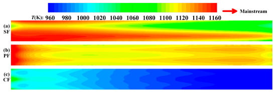
Figure 4.
Comparisons of the temperature contours of different minichannel configurations.
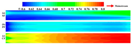
Figure 5.
Comparisons of the overall cooling effectiveness contours of different minichannel configurations.

Figure 6.
Comparisons of the temperature gradient contours of different minichannel configurations.
As can be seen in Figure 4a, the surface temperature of the SF structure presents a staggered distribution. The temperature near the inlet of MC1 is lower, but the temperature near the inlet of MC2 is significantly higher. The temperature distribution of the PF and CF structures decreases along the direction, which is obviously different from that of the SF. However, for the PF structure, as shown in Figure 4b, the temperature is higher when it impinges on the lamilloy near the upstream, which may be because the upstream of the lamilloy is in first contact with the mainstream, and there is also no film cooling effect. In Figure 4c, the temperature of the CF structure is significantly lower than that of the other two, which indicates that the heat transfer characteristic of the composite structure—combined with impingement cooling, convective heat transfer in the internal MCs, and film cooling—is significantly enhanced.
Figure 5 provides the local η distribution on the selected zone of the lamilloy. Within Figure 5a,b, the cooling effect at the downstream of the SF structure is higher, which is due to the impingement cooling of MC1; at the same time, this deteriorates the cooling effect of the MC2 upstream region. As well, by comparing it to Figure 5b,c, one can see that the cooling effect of the CF structure is significantly higher than that of the PF structure, which indicates that the film cooling configured in the CF structure plays a decisive role in improving the cooling effect on the upstream region with low cooling effectiveness, further improving the cooling effect on the downstream region.
In addition to that, the cooling effect is a common factor to assess the cooling of lamilloy, and the temperature uniformity is also important. Figure 6 provides the surface temperature gradient of three different structures. The temperature distribution of the SF structure is uneven, due to its staggered distribution, as shown in Figure 6a. As well, for Figure 6b,c, the PF and CF structures mainly have large temperature gradients at the upstream, which corresponds to the high temperature in this region. On the whole, the temperature gradient of the CF structure is the smallest, especially in the central part of the surface; that is, the CF structure has the best temperature uniformity, while ensuring the highest cooling effectiveness.
In order to quantitatively compare the heat transfer characteristic of the three structures, the averaged values of temperature, cooling effectiveness, and temperature gradient along direction is studied. Figure 7 shows the axial variations of the local temperature (), the local overall cooling effectiveness (ηx), and the local temperature gradient () for three MC arrangements. In Figure 7a,b, the ηx increases along the minichannel. As well, the CF has the maximum ηx over the entire surface, and is significantly higher than the other two. For the SF and PF, the ηx of the PF is better in the upstream, but lower in the downstream compared with the SF, which corresponds to Figure 4 and Figure 5. From Figure 7c, the temperature gradient of the three structures is larger at the two borders, and smaller in the central part of surface. However, the temperature gradient of the SF structure is much larger than the other two, and rises along the direction, which should be attributed to the impingement cooling of MC1. The temperature gradient of the CF structure is the largest in the upstream edge, and the smallest in other regions.
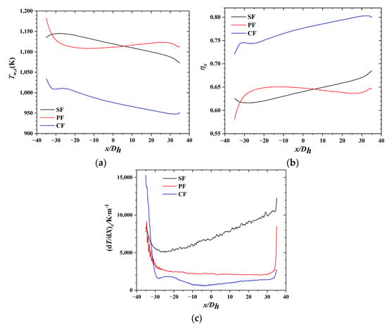
Figure 7.
Axial variations of the lamilloy surface. (a) local temperature, (b) local overall cooling effectiveness, (c) local temperature gradient.
The area-averaged temperature (), the area-averaged overall cooling effectiveness (ηave), and the area-averaged temperature gradient for three MC arrangements are listed in Table 2. The comparisons affirm that the CF structure has both the optimal cooling effect and uniformity. Specifically, the ηave of the CF increased by 20.6% and 20.4%, and the decreased by 76.9% and 32.8%, compared with the SF and PF, respectively. Additionally, the SF and PF have a similar ηave, but SF has the worst performance in thermal uniformity. Therefore, the CF structure has the highest cooling effectiveness and the best temperature uniformity, whilst the SF behaves the worst.

Table 2.
Heat transfer performance for different cases.
3.2. Flow Characteristic
For the lamilloy equipped with internal MCs in this work, it is crucial to obtain the detailed flow information. Since the two MCs of the SF and CF structures are exactly the same, only MC1 is analyzed for these two structures.
Figure 8 shows the axial variations of local temperature () and the local Darcy friction resistance coefficient () of the coolant in MCs. From Figure 8a, the of the coolant increases along the flow direction due to the convective heat transfer with the minichannel wall, while the temperature of MC1 in the CF structure increases the least, which indicates that it has the least heat exchange with the lamilloy through the minichannel wall. In Figure 8b, the decreases along the flow direction. To be specific, the presents a similar trend, which has a sudden drop in the entrance region of the minichannel, and then gradually drops until it reaches a stable value. In addition, the in MC1 of the SF and CF is significantly higher than the other two MCs, especially near the entrance, indicating that coolant flowing through these two MCs suffers greater friction resistance.
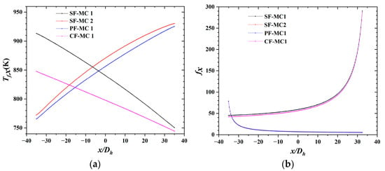
Figure 8.
Axial variations in the minichanne. (a) local temperature, (b) local .
In this work, the inlet and outlet of the minichannel are closely related to impingement cooling and film cooling, respectively. Figure 9 shows the streamline and velocity contours of the middle surface in different MCs. They all present a similar trend that the velocity increases along the flow direction, and then decreases at the outlet due to increasing cross-sectional area. At the entrance of each minichannel—that is, the impingement zone—when the airflow impinges on the channel, it immediately flows along the direction of the minichannel, and on the other side, a vortex appears. Additionally, there is some backflow at the outlet, and then it outflows rapidly, indicating that there is negative pressure in this position.
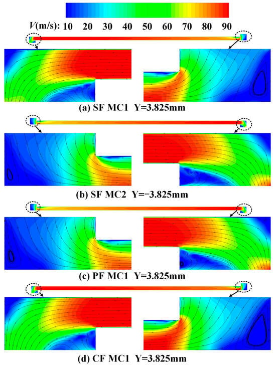
Figure 9.
Streamline and velocity contours of (a) MC1 of SF, (b) MC2 of SF, (c) MC1 of PF, (d) MC1 of CF.
Figure 10 presents the temperature contours in the middle surface of different MCs. Similar to velocity contours, temperature contours also present similar distribution characteristics. Namely, the temperature at the inlet is relatively low, which is basically the temperature of the coolant chamber. Along the flow direction, due to convective heat transfer with the MCs, the temperature gradually rises. The hottest temperature appears at the backflow region of the outlet, which corresponds to the velocity contours, as shown in Figure 9. Additionally, the outlet temperature of the CF structure is obviously low (shown in Figure 9d), which is consistent with Figure 8a.
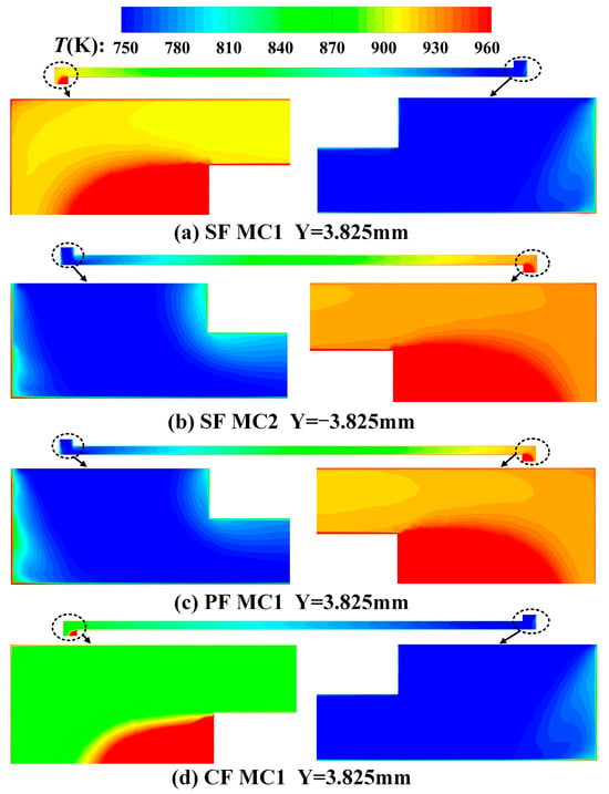
Figure 10.
Temperature contour of (a) MC1 of SF, (b) MC2 of SF, (c) MC1 of PF, (d) MC1 of CF.
To evaluate the effect of the coolant ejected from the minichannel on the original mainstream, Figure 11 shows the streamline and velocity contours in different mainstream chambers. In Figure 11a,d, the coolant ejected from the MCs completely blocks the direct contact between the mainstream and the lamilloy; however, instead of adhering to the lower surface, it creates a barrier through its large mass flow and velocity. As well, the velocity of the mainstream is significantly smaller under these two MCs, and compared with SF structure, the blue area near the film hole is wider in the CF structure, indicating that the film cooling effect of the CF structure is better. As for Figure 11b,c, the coolant directly flows out of the minichannel, so there is no effect of film cooling. However, as it is illustrated in Figure 11b, due to the backflow and negative pressure at the outlet of the MC2, part of the mainstream is attracted to this position so that there are more mainstreams below the MC2 of the SF structure, which also deteriorates the cooling here.

Figure 11.
Streamline and velocity contours of the mainstream chamber in (a) MC1 of SF, (b) MC2 of SF, (c) MC1 of PF, (d) MC1 of CF.
Figure 12 shows the temperature contours in different mainstream chambers. Seen in Figure 12a,d, the coolant ejected from the MCs makes the temperature here lower at the position of the film hole. Compared with Figure 12a, Figure 12d has a lower temperature in a larger range, indicating that the film cooling effect of the CF structure is better, which corresponds to Figure 11d. For Figure 12b,c, there is no difference in temperature, because there is no effect of film cooling.

Figure 12.
Temperature contour of the mainstream chamber in (a) MC1 of SF, (b) MC2 of SF, (c) MC1 of PF, (d) MC1 of CF.
In order to obtain the detailed mixing situation of coolant with the mainstream at different distances, Figure 13 presents the streamline and velocity contours at different sections ( = −3, −5, −7 mm), in different mainstream chambers. For the SF structure (shown in Figure 13a), due to the film hole at MC1 of the SF structure, the velocity at the outlet of the film hole is small, and most of the mainstream is transferred from the lower space of MC1 to the lower space of MC2: thus, the mainstream velocity at MC2 increases significantly. This will lead to an improved cooling effect in MC1, and a weakened cooling effect in MC2. At the same time, along the direction, that is, away from the film hole, the phenomenon gradually disappears. Different from the SF structure, instead of transferring the mainstream to another minichannel, the film hole of the CF structure transfers most of the mainstream to the lower position. In other words, both of the two parallel film holes improve the cooling effect. Moreover, the mainstream velocity is small in a wider area, indicating that the film cooling of this structure plays a large role in cooling enhancement.
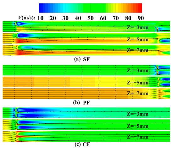
Figure 13.
T Streamline and velocity contours at different sections in the mainstream chamber for (a) SF structure, (b) SF structure, (c) CF structure.
Figure 14 presents the temperature contours at different sections ( = −3, −5, −7 mm), in different mainstream chambers. This shows that the temperature of the mainstream space of the CF structure is much smaller than that of the SF structure in the same section. On one hand, more coolant ejected from the minichannel of the CF structure results in more mixing. On the other hand, the smaller lamilloy temperature of the CF structure makes the mainstream temperature smaller. For the PF structure, since there is no film hole, there is no significant difference in the temperature of the mainstream under the lamilloy.
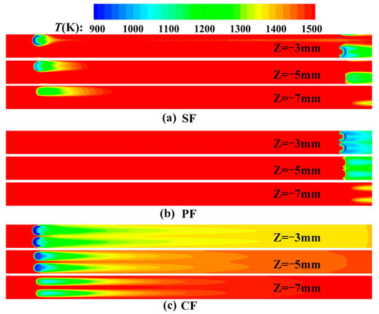
Figure 14.
Temperature contour at different sections in the mainstream chamber for (a) SF structure, (b) SF structure, (c) CF structure.
4. Conclusions
In this study, three different internal MC arrangements are studied and compared in detail. The temperature and its uniformity distributions within the lamilloy lower surface are analyzed in detail, and the average values are calculated. In addition, the detailed flow analysis of fluid domains is carried out, and different sections are selected to capture the flow characteristic. Considering the analysis above, several conclusions can be given below:
- For the SF structure, the η at downstream of the SF structure is higher due to the impingement cooling of MC1; but at the same time, this deteriorates the cooling effect of the region at MC2. Therefore, this structure has the worst cooling effect and temperature uniformity.
- The ηave of the CF structure increased by 20.6% and 20.4%, and the decreased by 76.9% and 32.8%, compared with the SF structure and the PF structure, respectively. Namely, the CF structure possesses the best cooling effect and temperature uniformity.
- The coolant ejected from the MC1 of the SF structure completely blocks the direct contact between the mainstream and the lamilloy, while transferring more from the mainstream to the MC2 region.
- Film cooling at the two outlet of the CF structure transfers most of the mainstream to the lower position, which further improves the cooling effect of the two MCs.
Author Contributions
Conceptualization, T.Y. and X.Z.; methodology, X.Z.; software, T.Y.; validation, T.Y. and Z.C.; formal analysis, Z.C.; investigation, L.X. (Liang Xu); resources, X.Z.; data curation, L.X. (Lei Xi); writing—original draft preparation, T.Y.; writing—review and editing, J.G.; visualization, L.X. (Liang Xu); supervision, L.X. (Lei Xi); project administration, W.K.; funding acquisition, X.J. All authors have read and agreed to the published version of the manuscript.
Funding
This research was funded by the National key research and development plan (2021YFF0602300).
Data Availability Statement
Data are contained within the article.
Conflicts of Interest
The authors declare no conflict of interest.
Nomenclature
| Biot number | |
| Specific heat capacity (J/kg K) | |
| Friction coefficient | |
| Heat transfer coefficient (W/m2 K) | |
| Mass flow ratio of coolant-to-mainstream | |
| Mass flow ratio of coolant-to-mainstream | |
| Mass flow rate of coolant (kg/s) | |
| Mass flow rate of mainstream (kg/s) | |
| Nusselt number | |
| Reynolds number | |
| Temperature ratio of mainstream-to-coolant | |
| Overall temperature of lamilloy (K) | |
| Temperature of coolant (K) | |
| Temperature of mainstream (K) | |
| Temperature ratio of coolant-to-mainstream | |
| Pressure drop (Pa) | |
| Overall cooling effectiveness | |
| Average overall cooling effectiveness | |
| Thermal conductivity of air (W/m K) | |
| Thermal conductivity of 314 (W/m K) | |
| Density of air (kg/) | |
| Dynamic viscosity (Pa·s) | |
| inclination angles () |
References
- Leger, B.; Miron, P.; Emidio, J.M. Geometric and aero-thermal influences on multiholed plate temperature application on combustor wall. Int. J. Heat Mass Transf. 2003, 46, 1215–1222. [Google Scholar] [CrossRef]
- Gustafsson, K.M.B.; Johansson, T.G. An experimental study of surface temperature distribution on effusion-cooled plates. J. Eng. Gas Turbines Power 2001, 123, 308–316. [Google Scholar] [CrossRef]
- Wang, J.; Hu, Z.; Du, C.; Tian, L.; Baleta, J. Numerical study of effusion cooling of a gas turbine combustor liner. Fuel 2021, 294, 120578. [Google Scholar] [CrossRef]
- Bunker, R.S. Film Cooling Effectiveness Due to Discrete Holes Within a Transverse Surface Slo. In Proceedings of the ASME Turbo Expo 2002, Amsterdam, The Netherlands, 3–6 June 2002; Volume 36088, pp. 129–138. [Google Scholar]
- Vishal, V.; Sriraam, J.; Subhash, K.; Kishore, V.R.; Srikrishnan, A.R.; Balajee, R.; Suresh, B. Studies on effusion cooling: Impact of geometric parameters on cooling effectiveness and coolant consumption. Aerosp. Sci. Technol. 2018, 77, 58–66. [Google Scholar]
- Kusterer, K.; Bohn, D.; Sugimoto, T.; Tanaka, R. Double-Jet Ejection of Cooling Air for Improved Film Cooling. J. Turbomach. 2007, 129, 809–815. [Google Scholar] [CrossRef]
- Zhou, J.; Wang, X.; Li, J.; Lu, H. CFD analysis of mist/air film cooling on a flat plate with different hole types. Numer. Heat Transf. Part A Appl. 2017, 71, 1123–1140. [Google Scholar] [CrossRef]
- Kiyici, F.; Topal, A.; Hepkaya, E.; Inanli, S. Numerical Investigation of Gas Turbine Combustor Liner Film Cooling Slots. In Proceedings of the ASME Turbo Expo 2018 Turbomachinery Technical Conference and Exposition GT2018, Oslo, Norway, 11–15 June 2018. [Google Scholar]
- Lee, H.-W.; Park, J.J.; Le, J.S. Flow visualization and film cooling effectiveness measurements around shaped holes with compound angle orientations. Int. J. Heat Mass Transf. 2002, 45, 145–156. [Google Scholar] [CrossRef]
- Zhang, X.D.; Liu, J.J.; An, B.T. The influences of element layout and coolant ejection angle on overall cooling effectiveness of laminated cooling configuration. Int. J. Heat Mass Transf. 2016, 101, 988–991. [Google Scholar] [CrossRef]
- Liu, K. Heat transfer characteristics of triple-stage impingement designs and their application for industrial gas turbine combustor liner cooling. Int. J. Heat Mass Transf. 2021, 172, 121174. [Google Scholar] [CrossRef]
- Yoko, M.J.; Sun, X.; van der Spuy, S.J.; Sethi, V. Multi-fidelity modelling of an impingement/effusion cooled gas turbine combustor liner. Appl. Therm. Eng. 2021, 185, 116318. [Google Scholar] [CrossRef]
- Zhang, J.; Han, H.Z.; Li, Z.R.; Zhong, H.G. Effect of pin-fin forms on flow and cooling characteristics of three-layer porous laminate. Appl. Therm. Eng. 2021, 194, 117084. [Google Scholar] [CrossRef]
- Liu, X.; Zhang, C.; Song, L.; Li, J. Influence of Biot number and geometric parameters on the overall cooling effectiveness of double wall structure with pins. Appl. Therm. Eng. 2021, 198, 117439. [Google Scholar] [CrossRef]
- Zhang, X.D.; Liu, J.J.; An, B.T. The investigations of slot film outflow used on the laminated cooling configuration. Int. J. Heat Mass Transf. 2019, 141, 1078–1086. [Google Scholar] [CrossRef]
- Wang, G.; Niu, D.; Xie, F.; Wang, Y.; Zhao, X.; Ding, G. Experimental and numerical investigation of a microchannel heat sink (MCHS) with micro-scale ribs and grooves for chip cooling. Appl. Therm. Eng. 2015, 85, 61–70. [Google Scholar] [CrossRef]
- Deng, D.; Xie, Y.; Chen, L.; Pi, G.; Huang, Y. Experimental investigation on thermal and combustion performance of a combustor with microchannel cooling. Energy 2019, 181, 954–963. [Google Scholar] [CrossRef]
- Chen, Z.; Feng, Z.; Zhang, Q.; Zhang, J.; Guo, F. Effects of regular triangular prisms on thermal and hydraulic characteristics in a minichannel heat sink. Int. J. Heat Mass Transf. 2022, 188, 122583. [Google Scholar] [CrossRef]
- Moradikazerouni, A.; Afrand, M.; Alsarraf, J.; Mahian, O.; Wongwises, S.; Tran, M.-D. Comparison of the effect of five different entrance channel shapes of a micro-channel heat sink in forced convection with application to cooling a supercomputer circuit board. Appl. Therm. Eng. 2019, 150, 1078–1089. [Google Scholar] [CrossRef]
- You, J.; Feng, H.; Chen, L.; Xie, Z.; Xia, S. Constructal design and experimental validation of a non-uniform heat generating body with rectangular cross-section and parallel circular cooling channels. Int. J. Heat Mass Transf. 2020, 148, 119028. [Google Scholar] [CrossRef]
- Osman, O.S.; El-Zoheiry, R.M.; Elsharnoby, M.; Nada, S.A. Performance enhancement and comprehensive experimental comparative study of cold plate cooling of electronic servers using different configurations of mini-channels flow. Alex. Eng. J. 2021, 60, 4451–4459. [Google Scholar] [CrossRef]
- Kanargi, B.; Lee, P.S.; Yap, C. A numerical and experimental investigation of heat transfer and fluid flow characteristics of an air-cooled oblique-finned heat sink. Int. J. Heat Mass Transf. 2018, 116, 393–416. [Google Scholar] [CrossRef]
- Radwan, A.; Ahmed, M. The influence of microchannel heat sink configurations on the performance of low concentrator photovoltaic systems. Appl. Energy 2017, 206, 594–611. [Google Scholar] [CrossRef]
- Chiu, H.-C.; Jang, J.-H.; Yeh, H.-W.; Wu, M.-S. The heat transfer characteristics of liquid cooling heatsink containing microchannels. Int. J. Heat Mass Transf. 2011, 54, 34–42. [Google Scholar] [CrossRef]
- Yu, C.; Park, J.; Youn, J.R.; Song, Y.S. Integration of form-stable phase change material into pyroelectric energy harvesting system. Appl. Energy 2022, 307, 118212. [Google Scholar] [CrossRef]
- Yang, T.; Sun, Y.; Xu, L.; Yang, X.; Duan, D.; Xi, L.; Gao, J.; Li, Y. Flow and heat transfer characteristics in cooling lamilloy with internal MCs. Int. J. Heat Mass Transf. 2022, 201, 123645. [Google Scholar] [CrossRef]
- Kemerli, U.; Kahveci, K. Conjugate forced convective heat transfer in a sandwich panel with a Kagome truss core: The effects of strut length and diameter. Appl. Therm. Eng. 2020, 167, 114794. [Google Scholar] [CrossRef]
- Sutherland, W. LII. The viscosity of gases and molecular force. Lond. Edinb. Dublin Philos. Mag. J. Sci. 2009, 36, 507–531. [Google Scholar] [CrossRef]
- Li, Y.; Xie, G.; Zhang, Y.; Ferla, P.; Sunden, B. Flow Characteristics and Heat Transfer of Supercritical n-decane in Novel Nested Channels for Scramjet Regenerative Cooling. Int. J. Heat Mass Transf. 2021, 167, 120836. [Google Scholar] [CrossRef]
- Lee, S.M.; Kim, K.Y. Comparative study on performance of a zigzag printed circuit heat exchanger with various channel shapes and configurations. Heat Mass Transf. 2013, 49, 1021–1028. [Google Scholar] [CrossRef]
- Menter, F.R. Two-equation eddy-viscosity turbulence models for engineering applications. AIAA J. 1994, 32, 1598–1605. [Google Scholar] [CrossRef]
- Wei, W.; Jian, P.; Jianhua, W.; Weilong, W.; Ming, W. An experimental investigation on cooling characteristics of a vane laminated end-wall with axial-row layout of film-holes. Appl. Therm. Eng. 2019, 148, 953–962. [Google Scholar]
Disclaimer/Publisher’s Note: The statements, opinions and data contained in all publications are solely those of the individual author(s) and contributor(s) and not of MDPI and/or the editor(s). MDPI and/or the editor(s) disclaim responsibility for any injury to people or property resulting from any ideas, methods, instructions or products referred to in the content. |
© 2023 by the authors. Licensee MDPI, Basel, Switzerland. This article is an open access article distributed under the terms and conditions of the Creative Commons Attribution (CC BY) license (https://creativecommons.org/licenses/by/4.0/).