Article

Distributed Modeling of Isolated Active Magnetic Bearings Considering Magnetic Leakage and Material Nonlinearity

School of Electrical Engineering, Harbin Institute of Technology, Harbin 150001, China
*
Author to whom correspondence should be addressed.
Energies 2023, 16(24), 8023; https://doi.org/10.3390/en16248023
Submission received: 23 November 2023 / Revised: 7 December 2023 / Accepted: 10 December 2023 / Published: 12 December 2023
(This article belongs to the Special Issue Linear/Planar Motors and Other Special Motors)

Abstract

:
In order to expand the application field of magnetic bearings, this article studies a novel radially isolated active magnetic bearing (IAMB) system in which the stator and the rotor are separated by a layer of metal isolation sleeve. Aimed at the shortcomings of existing modeling methods, a distributed magnetic circuit model (DMCM) was proposed based on the magnetic field segmentation theory for IAMBs. Considering material nonlinearity and leakage flux, the flux distributions of the isolation sleeve and air gap are calculated accurately. Finally, the 3D finite element model (3D FEM) and experimental platform were built to verify the feasibility of the IAMB and the correctness of the DMCM.

1. Introduction

As a noncontact support and guide device, the active magnetic bearing (AMB) has the advantages of no wear, long service life, diversified structure, and high speed [1,2], and can replace the traditional mechanical bearing structure [3]. It is widely used in electric vehicles, turbo compressors, aerospace, and other fields [4,5,6].
The stator and rotor of the traditional AMB are only separated by an air gap, and the working environment is relatively simple. It can only work in a relatively good environment such as one of normal temperature, normal pressure, and dryness, and the working environment of the stator and the rotor must be consistent [7,8]. As more cutting-edge fields propose to replace mechanical bearings with magnetic bearings, higher requirements are placed on the control accuracy and environmental adaptability of magnetic bearings. Traditional AMBs are no longer applicable when the rotors work in harsh environments such those of as high temperature, high pressure, and liquids. In this paper, a novel radially isolated active magnetic bearing (IAMB) is studied. A layer of annular, metal, magnetic isolation sleeve separates the stator and rotor. The stator and rotor of the IAMB can work in different environments, respectively. Compared with the traditional AMB, the IAMB can be applied in a wider field and has broad application prospects.
The addition of the spacer sleeve makes the magnetic flux path between the stator and rotor of the magnetic bearing more complicated. There is stronger nonlinearity and coupling between the suspension force and the control current, and the flux leakage coefficient is exacerbated. Therefore, establishing an accurate mathematical model of suspension force plays a key role in the design and suspension control of an IAMB.
Among the current modeling methods for magnetic bearings, the equivalent magnetic circuit method is the most widely used, because it is simple and intuitive, but it is not accurate enough [9,10,11,12,13]. In [14,15,16,17], an improved modeling method that considers fringing flux and leakage flux is proposed, which improves the accuracy of the equivalent magnetic circuit method. However, due to the rough consideration of edge flux and leakage flux, the calculation accuracy is not significantly improved. In [18], by accurately segmenting the magnetic field, a modeling method that can accurately calculate the edge flux and leakage coefficient is proposed, and the accuracy of the modeling results is greatly improved. In [19], a magnetic bearing suspension force model based on the Maxwell tensor method was established, and a multilevel optimization design scheme was proposed. In this paper, the magnetic field segmentation and reluctance calculation of the inner and outer air gaps of the isolation sleeve are carried out using this method. In [20], a hybrid analytical model combining the elementary subdomain method and the equivalent magnetic circuit method is proposed, which can obtain an accurate solution considering the rotor eccentricity and saturation effects, but this method is analytically complex and computationally intensive. The calculation result cannot be obtained in a short time, and it is not suitable for the preliminary design of magnetic bearings. The previous research results on the modeling technology of magnetic bearings have been quite accurate, but they are all aimed at traditional magnetic bearings in the form of a stator-air gap-rotor model, which are not applicable to IAMBs. Because the magnetic circuit complexity and control difficulty of IAMBs are higher than those of traditional AMBs, it is urgent to establish an accurate, equivalent magnetic circuit mathematical model for IAMBs in order to realize the rapid design of IAMBs. The DMCM proposed in this paper solves the problem that the traditional magnetic circuit model of an AMB is not suitable for an IAMB and provides guidance for the design of the IAMB. The DMCM based on the theory of magnetic field segmentation considers the problems of magnetic leakage, edge effect, magnetic saturation, and rotor eccentricity at the same time; it has a high accuracy and does not occupy a lot of computing resources, and has a broad application prospect, which can also be applied to other isolated devices.
First of all, this paper analyzes the magnetic flux distribution in an IAMB, especially in the isolation sleeve and the two-layer air gap and divides the magnetic flux region accurately. An accurate mathematical model of suspension force suitable for the IAMB is established, taking into account the leakage flux and fringing flux. Then, a three-dimensional finite element model is established, and a related experimental platform is built. The accuracy of the model is verified using stiffness comparison experiments. Finally, after the suspension force model is applied to the control system, the convergence of the IAMB in stable suspension is greatly improved, which verifies the correctness and superiority of this modeling method and its good anti-interference characteristics.

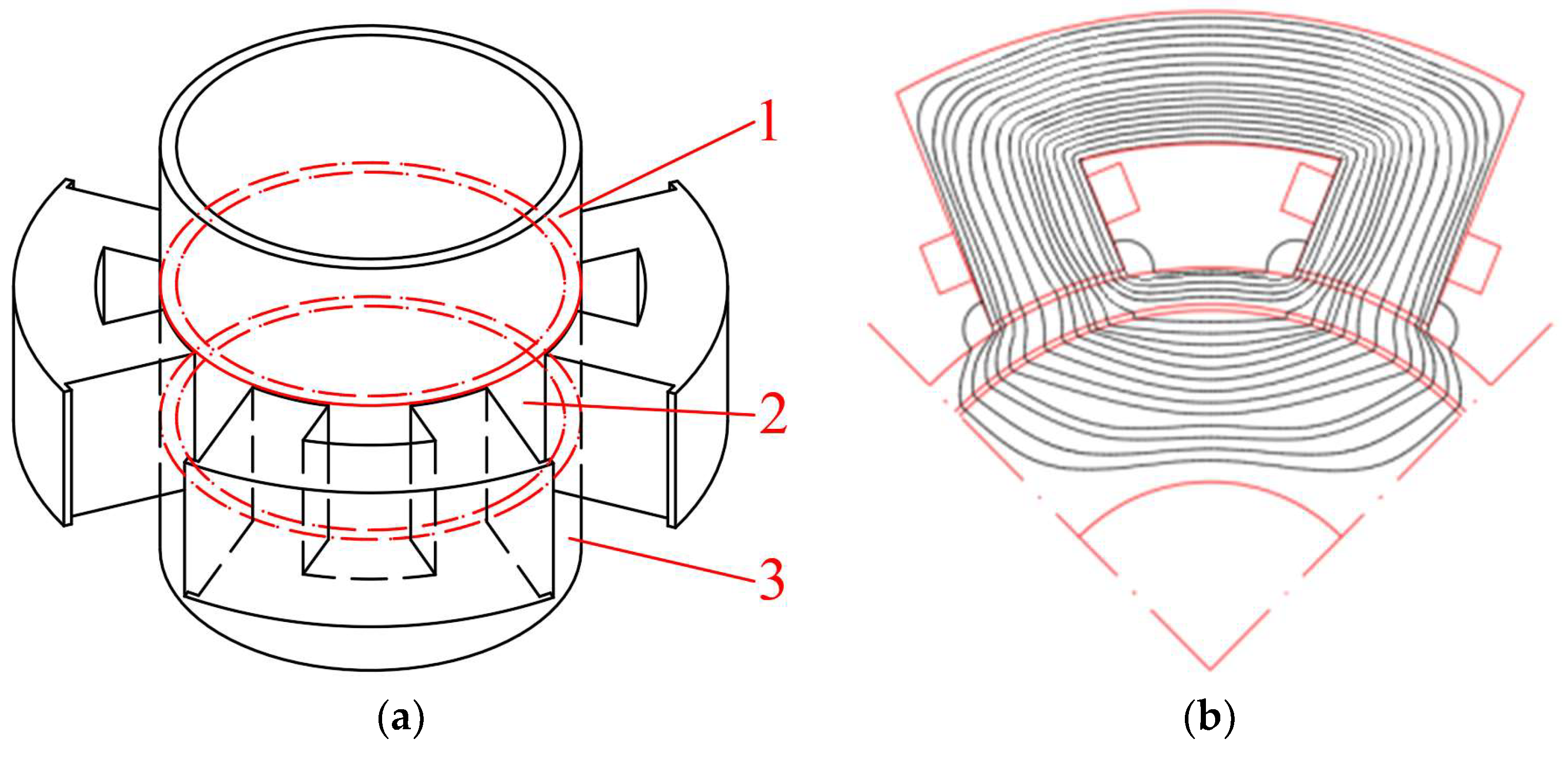
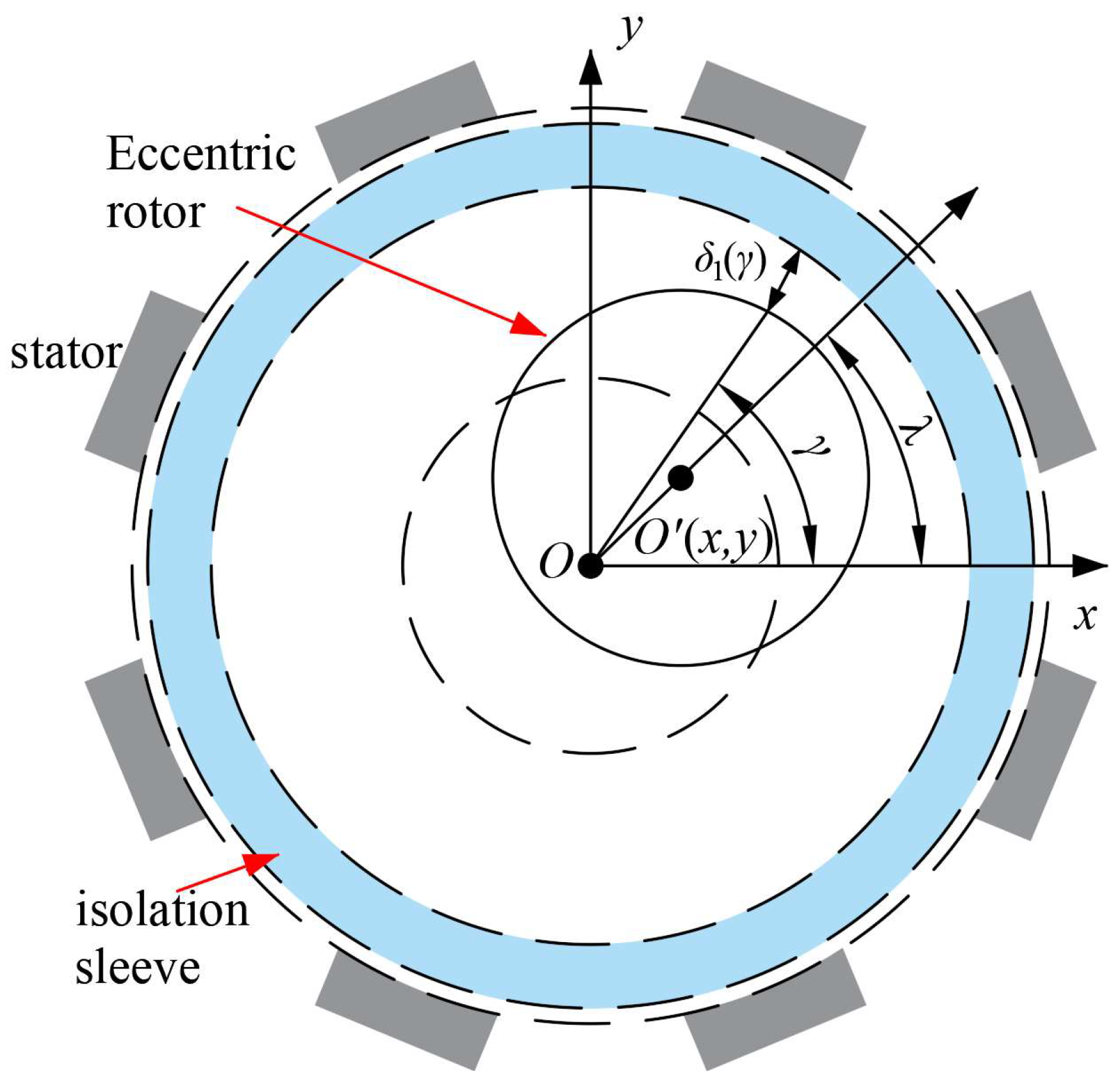
2. Configuration and Principle

The structure and explosion diagram of the IAMB are shown in Figure 1a, and the stator is an eight-pole radial structure. Different from the traditional AMB, a layer of metal isolation sleeve made of 12Cr13 completely separates the stator and rotor of the IAMB, so that the working environments of the stator and rotor do not affect each other.
In Figure 1b, two coils with opposite directions are respectively set on a pair of magnetic poles in the same direction in series as a group, which is driven by a switching power amplifier. NNSS arrangement is adopted between the magnetic poles to reduce coupling. The main magnetic flux represented by the red dashed line exerts an effective electromagnetic force on the rotor. This flux enters the isolation sleeve via the stator pole, passing through air gap 2 (the air gap between the isolation sleeve and the magnetic pole) and subsequently enters the rotor through air gap 1 (the air gap between the isolation sleeve and the rotor) to complete a closed loop. On the other hand, the blue dashed line represents the leakage flux. Notably, a substantial portion of the magnetic flux that enters the isolation sleeve via air gap 2 forms a closed loop within the sleeve, representing the primary component of the leakage flux in the IAMB.
Figure 1c shows the structural parameters of the IAMB under a pair of magnetic poles. Here, rsi is the radius of the inner surface of the stator yoke, rs is the radius of the outer surface of the stator, xc is the width of the stator teeth, h is the length of the stator pole, rr is the radius of the outer surface of the rotor, rf is the radius of the inner surface of the rotor, ri is the radius of the outer surface of the isolation sleeve, rin is the radius of the inner surface of the isolation sleeve, α is the angle between the center lines of adjacent magnetic poles, β is the radian between a pair of magnetic poles, θ is the radian of a single magnetic pole, δi is the thickness of the isolation sleeve, δ1 is the length of air gap 1 when the rotor is not eccentric, and δ2 is the length of air gap 2.

3. Magnetic Model and Calculation Procedures

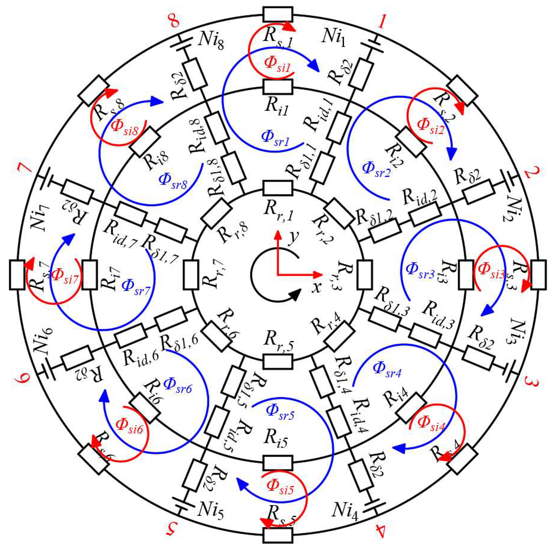
3.1. Establishment of Distributed Magnetic Circuit Model

The addition of the isolation sleeve separates the air gap between the stator and the rotor into two layers, and the magnetic flux path is more complicated. According to the different magnetic flux flow directions, the DMCM is established, as shown in Figure 2. Taking the central position of each magnetic pole as the node, the IAMB is equally divided into eight parts in the circumferential direction to obtain eight magnetic loops. Here, n represents the number of nodes (segments or loops) in the model, n ∈ [1, 8].
Accurately calculating the leakage flux caused by the isolation sleeve, as well as the flux of air at both sides of the isolation sleeve, is crucial for improving the accuracy of the IAMB model.

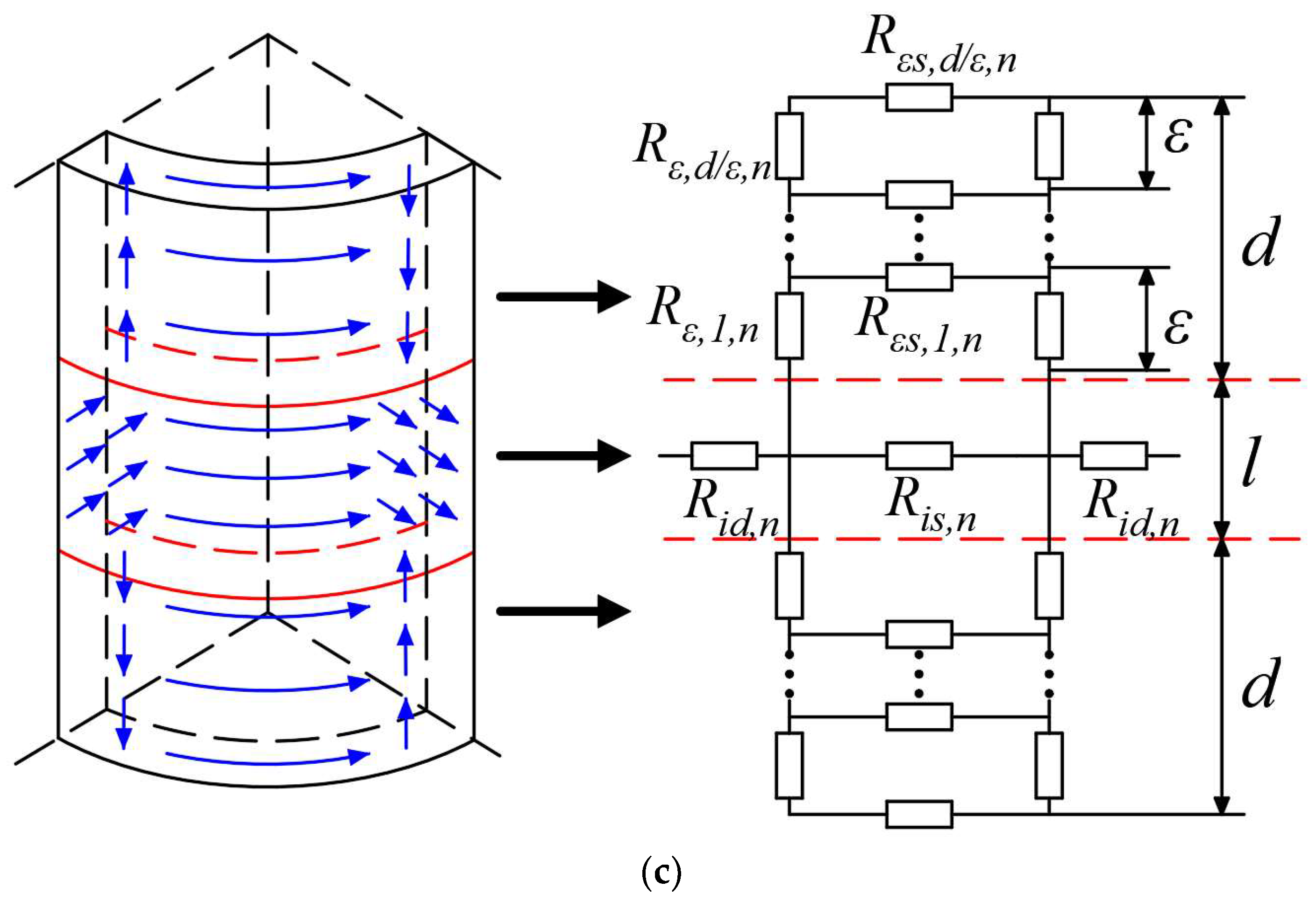
3.2. Calculation of Axial Segmental Magnetic Network

As shown in Figure 3a, since the axial length of the isolation sleeve is greater than that of the stator and rotor, there are radial, circumferential, and axial fluxes in the system. Therefore, the system needs to be divided into three sections along the axis according to the flux path. Segment 2 is the section corresponding to the axial length l of the stator and rotor, and segments 1 and 3 are the axial extension segments of the isolation sleeve. The magnetic fields of the isolation sleeve and the air gap inside and outside of it are segmented accurately to obtain the related reluctance.

3.2.1. Calculation of Reluctance of Isolation Sleeves

The flux path in the isolation sleeve is relatively complex. As shown in Figure 3b, in the isolation sleeve of segment 2, the magnetic flux paths are distributed along the radial and circumferential directions, and reluctance calculation is carried out in this section according to the 2-dimensional model. The expressions of the reluctance Ris,n and Rid,n of the isolation sleeve in the circumferential direction and in the radial direction in segment 2 can be calculated as:
R i s , n = r i β μ 0 μ i , n δ i l , n [ 1 ,   8 ]
R i d , n = δ i μ 0 μ i , n r i l ( θ + 0.375 β ) , n [ 1 ,   8 ]
where l is the axial length of the stator and rotor, μ0 is the permeability of vacuum, and μi,n is the relative permeability of the isolation sleeve in segment 2.
Assuming the isolation sleeve is long enough, the magnetic flux of the isolation sleeve in segments 1 and 3 is along the axial and circumferential directions, and the infinite parallel reluctance network is adopted for reluctance calculation. The magnetic flux path and equivalent reluctance network are shown in Figure 3c. The magnetic density in the isolation sleeve decreases with the increase of axial length. It is assumed that the effective length of the isolation sleeve is d, and the magnetic density within the effective length is greater than Bmin, which is usually 0.2 T. d can be calculated as:
d n = β r i 2 ( B i s , n B min 1 ) , n [ 1 ,   8 ]
where Bis,n is the magnetic density of the isolation sleeve in segment 2. Within the effective axial length d, it is divided into cell segments of length ε, with a total of d/ε segments. Therefore, according to the flux continuity theorem and ampere loop theorem, it can be concluded that the circumferential density Bεs,k,n and axial density Bε,k,n of segments 1 or 3 of the isolation sleeve in cell segment k are:
{ B ε s , k , n = 2 B i s , n β r i k 2 ε 2 2 β r i + 2 β r i B ε , k , n = t = k d / ε B ε s , t , n ε θ r i , k [ 1 , d ε ] , n [ 1 ,   8 ]
The axial and radial reluctance of the isolation sleeve within the length ε in cell segment k can be obtained as:
{ R ε s , k , n = β r i μ 0 μ ε s , k , n δ i ε R ε , k , n = ε μ 0 μ ε , k , n δ i x c , k [ 1 , d ε ] , n [ 1 ,   8 ]
According to the flow chart in Figure 4, after calculating the reluctance of each cell segment, the total axial leakage reluctance Riz,n of the isolation sleeve can be calculated by the iterative.
On the path of the isolation sleeve along the radial and axial directions, the magnetic flux directly forms a loop without interlinking the rotor. The total reluctance of this part is:
R i , n = R i s , n R i z , n R i z , n = R i s , n R i z , n 2 R i s , n + R i z , n , n [ 1 ,   8 ]

3.2.2. Calculation of Reluctance of Air Gap

The air gap between the rotor and the isolation sleeve is the working air gap (air gap 1), and the length of it when the rotor is not eccentric is δ1. The air gap between the isolation sleeve and the stator poles is the assembly air gap caused by the clearance fit (air gap 2), and the length of it is δ2. In the case of ensuring good assembly, δ2 is generally 0.01–0.05 mm, and it can reach 0.1 mm when the machining error is large. The existence of the assembly air gap increases the reluctance of the common magnetic circuit, so its reluctance cannot be ignored. However, due to δ2 << xc, the influence of eccentricity on its reluctance can be ignored when the concentric tolerance between the stator and the isolation sleeve is properly designed.
When the rotor is disturbed and deviates from the equilibrium position, the air gap lengths at different angles along the circumference in the air gap 1 are no longer equal. Figure 5 is the rotor eccentricity diagram. When the rotor center moves from O (0,0) to O’ (x,y), the eccentric angle λ and eccentricity rate σ can be expressed as:
{ λ = { arctan ( y / x ) , x > 0 arctan ( y / x ) + π , x < 0 σ = x 2 + y 2 δ 1
At the angle γ along the circumference, the length of the air gap between the rotor and the isolation sleeve is:
δ 1 ( γ ) = δ 1 [ 1 σ cos ( γ λ ) ]
Figure 6 shows the division of the magnetic flux regions for air gap 1 and air gap 2, respectively. As shown in Figure 6a, region “a” of air gap 1 is the part corresponding to the outer surface of the rotor and the isolation sleeve, which is the area corresponding to the main magnetic permeance, denoted as Λa,n; region “b” and region “c” are, respectively, the solid ring body and the hollow ring tube, which are the regions corresponding to the axial leakage permeance, and are denoted as Λb and Λc, respectively. When the rotor deviates from the balance position, the corresponding air-gap permeability can be calculated as [18]:
{ Λ a , n = μ 0 S r 2 δ 1 ( γ ) = μ 0 r r l 3 β 2 + θ ( n 1 ) π 4 3 β 2 + 2 θ ( n 1 ) π 4 1 δ 1 ( γ ) d γ Λ b = π μ 0 r r ( β + θ ) 11.9 Λ c = μ 0 r r ( β + θ ) 2 π , n [ 1 ,   8 ]
The total reluctance of air gap 1 is calculated as:
R δ 1 , n = 1 Λ a , n + 2 Λ b + 2 Λ c = 1 μ 0 r r [ l 3 β 2 + θ ( n 1 ) π 4 3 β 2 + 2 θ ( n 1 ) π 4 1 δ 1 ( γ ) d γ + 0.846 ( β + θ ) ]
In Figure 6b, area 1 of air gap 2 is the part of the air gap corresponding to the stator tooth surface, which is the area corresponding to the main magnetic permeance, and is denoted as Λ1; regions 2 to 7 are edge regions, in which regions 2 and 6 are solid rings, regions 3 and 7 are hollow rings, and regions 4 and 5 are solid balls and hollow spherical shells, respectively, and the magnetic permeance of each part is represented as Λ2 to Λ7. Therefore, the air-gap permeance in each region can be calculated as [18]:
{ Λ 1 = μ 0 r i θ l δ 2 , Λ 2 = π μ 0 θ r i 5.95 Λ 3 = μ 0 θ r i π , Λ 4 = μ 0 π δ 2 10.61 Λ 5 = μ 0 δ 2 , Λ 6 = μ 0 π l 5.95 , Λ 7 = μ 0 l π
Then, the total reluctance of air gap 2 can be calculated as:
R δ 2 = 1 Λ 1 + 2 ( Λ 2 + Λ 3 + Λ 6 + Λ 7 ) + 4 ( Λ 4 + Λ 5 ) = 1 μ 0 r i θ l δ 2 + 1.7 μ 0 ( r i θ + l ) + 5.2 μ 0 δ 2
According to the geometrical dimensions of the stator and rotor of the IAMB, their reluctance can be obtained as follows:
R s , n = { α ( r s + r s i ) 2 μ 0 μ s , n l ( r s r s i ) + 2 h μ 0 μ s , n x c l , n = 1 , 3 , 5 , 7 α ( r s + r s i ) 2 μ 0 l ( r s r s i ) + 2 h μ 0 μ s , n x c l , n = 2 , 4 , 6 , 8
R r , n = π ( r r + r f ) 4 μ 0 μ r , n l ( r r r f )
where μs,n is the relative permeability of the stator, and μr,n is the relative permeability of the rotor.

3.2.3. Calculation of Magnetic Flux and Suspension Forces

As shown in Figure 2, Φsr1sr8 and Φsi1si8 are the magnetic fluxes of the 8 loops closed by the rotor and the 8 loops directly closed by the isolation sleeve, respectively. The corresponding magnetic circuit equation is as follows:
{ U ( 1 × 8 ) = Φ s r ( 1 × 8 ) R s r ( 8 × 8 ) + Φ s i ( 1 × 8 ) R i r ( 8 × 8 ) U ( 1 × 8 ) = Φ s i ( 1 × 8 ) R s i ( 8 × 8 ) + Φ s r ( 1 × 8 ) R i r ( 8 × 8 )
Among it, the reluctance matrix for the magnetic circuit of the isolation sleeve Rsi(8×8) is:
R n n = ( 2 R δ 2 + R s , n + R i , n )
{ R n ( n + 1 ) = R ( n + 1 ) n = R δ 2 , n [ 1 ,   7 ] R 81 = R 18 = R δ 2 , n = 8
The reluctance matrix for the magnetic circuit of rotor Rsr(8×8) is:
R n n = { 2 R δ 2 + R i d , 8 + R i d , 1 + R δ 1 , 8 + R δ 1 , 1 + R s , 1 + R r , 1 , n = 1 2 R δ 2 + R i d , n 1 + R i d , n + R δ 1 , n 1 + R δ 1 , n + R s , n + R r , n , n [ 2 ,   8 ]
{ R n ( n + 1 ) = R ( n + 1 ) n = ( R δ 2 + R i d , n + R δ 1 , n ) , n [ 1 ,   7 ] R 18 = R 81 = ( R δ 2 + R i d , 8 + R δ 1 , 8 ) , n = 8
Rir(8×8) is the reluctance matrix of the common magnetic circuit, and the element calculation is as follows:
R n n = 2 R δ 2 + R s , n
{ R n ( n + 1 ) = R ( n + 1 ) n = R δ 2 , n [ 1 ,   7 ] R 81 = R 18 = R δ 2 , n = 8
The two types of magnetic circuits share the magnetomotive force, and the magnetomotive force matrix U(1×8) is:
U n = { U 1 = N ( i 8 + i 1 ) U 2 = N ( i 2 i 1 ) U 3 = N ( i 2 + i 3 ) U 4 = N ( i 3 i 4 ) U 5 = N ( i 4 + i 5 ) U 6 = N ( i 6 i 5 ) U 7 = N ( i 6 + i 7 ) U 8 = N ( i 7 i 8 ) { i 8 = i 1 = I 0 + i y i 4 = i 5 = I 0 i y i 2 = i 3 = I 0 + i x i 6 = i 7 = I 0 i x
where I0 is the bias current, N is the turn of a control coil, and ix and iy are the control currents in the x and y directions, respectively. When the rotor deviates from the equilibrium position, such as in the direction of x+, by increasing i6, i7 and decreasing i2, i3, a suspension force in the direction of x- is generated, so that the rotor returns to the equilibrium position. Then, according to the Maxwell tension tensor, the suspension force in the x and y directions on the rotor can be calculated as:
{ F x = ( Φ s r 2 Φ s r 3 ) 2 + ( Φ s r 4 Φ s r 3 ) 2 ( Φ s r 8 Φ s r 7 ) 2 ( Φ s r 6 Φ s r 7 ) 2 2 μ 0 r r θ l cos ( α 2 ) + ( Φ s r 1 Φ s r 2 ) 2 + ( Φ s r 5 Φ s r 4 ) 2 ( Φ s r 1 Φ s r 8 ) 2 ( Φ s r 5 Φ s r 6 ) 2 2 μ 0 r r θ l sin ( α 2 ) F y = ( Φ s r 1 Φ s r 2 ) 2 + ( Φ s r 1 Φ s r 8 ) 2 ( Φ s r 5 Φ s r 6 ) 2 ( Φ s r 5 Φ s r 4 ) 2 2 μ 0 r r θ l cos ( α 2 ) + ( Φ s r 2 Φ s r 3 ) 2 + ( Φ s r 8 Φ s r 7 ) 2 ( Φ s r 4 Φ s r 3 ) 2 ( Φ s r 6 Φ s r 7 ) 2 2 μ 0 r r θ l sin ( α 2 )

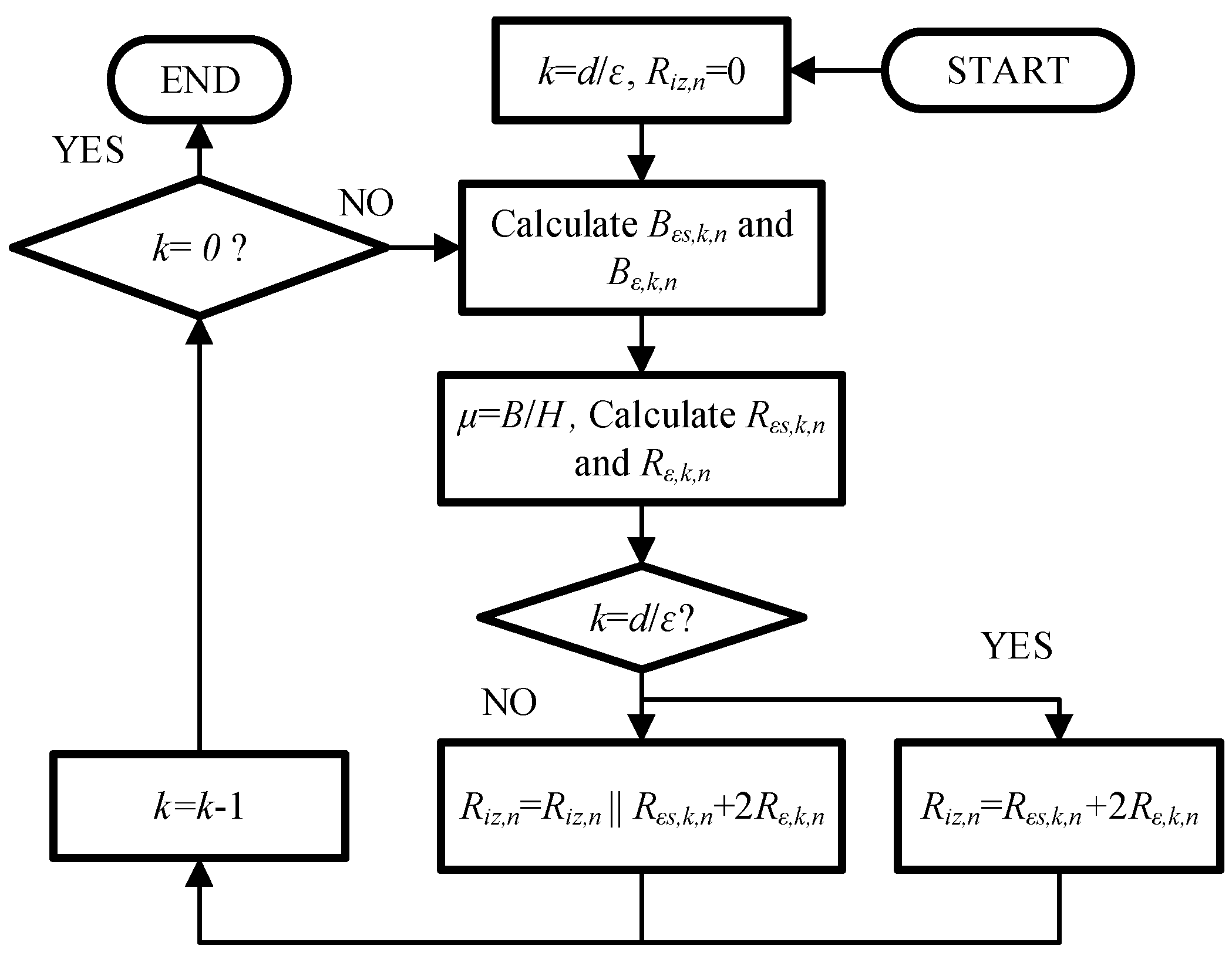
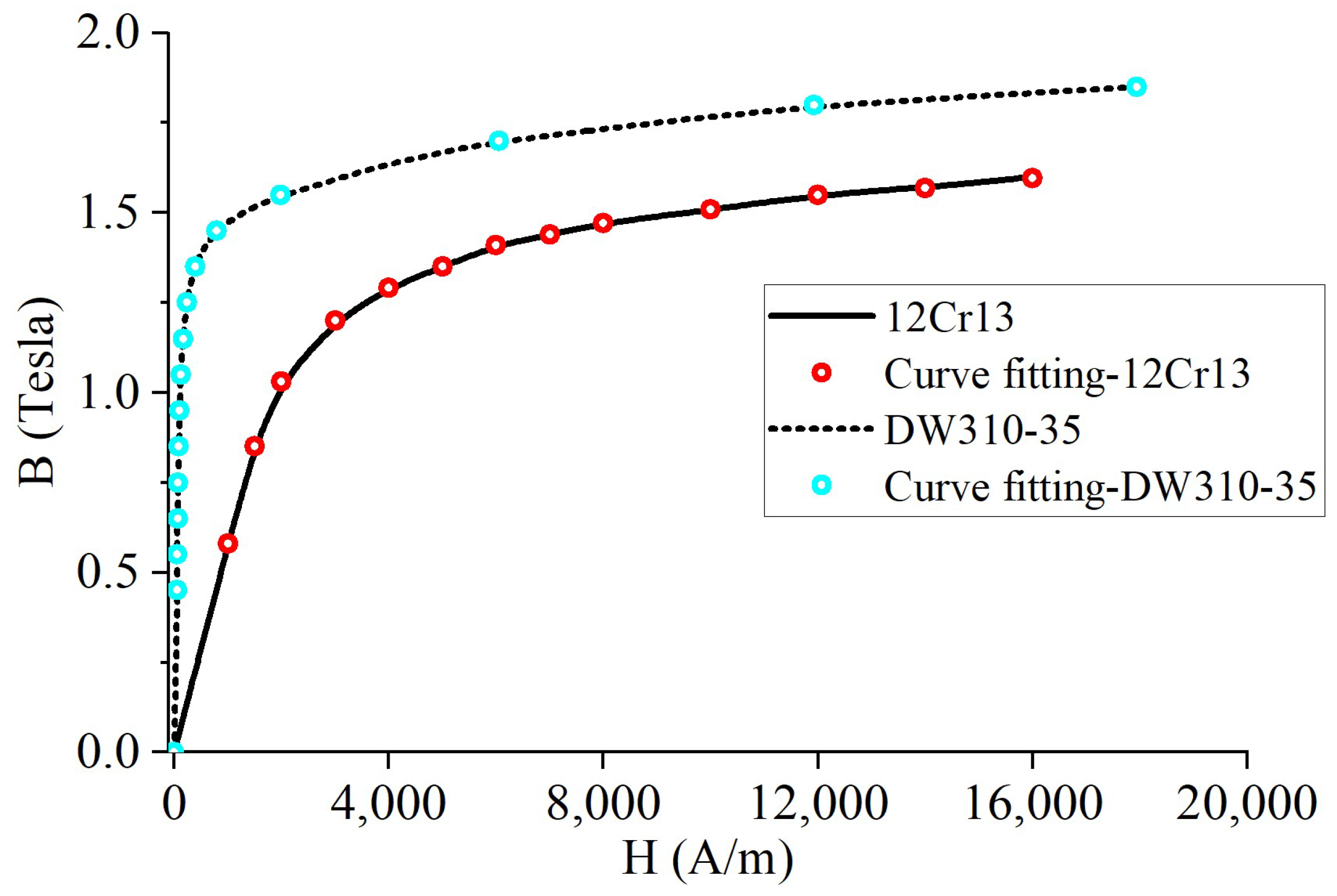
3.2.4. Iterative Calculation and Nonlinearity of Materials

In order to maximize the current stiffness of the IAMB, it is necessary to increase the magnetic flux, forming a loop through the rotor. The effective way is to saturate the magnetic circuit of the isolation sleeve with the magnetic flux generated by the bias current. At this time, the reluctance of the isolation sleeve magnetic circuit is very large, and the magnetic flux generated by the control current mainly forms a loop through the rotor.
Therefore, the saturation effect of ferromagnetic material in the magnetic circuit of the IAMB cannot be ignored. Ferromagnetic material DW310-35 of the stator and rotor and material 12Cr13 of the isolation sleeve were fitted using the cubic spline method, and the fitting curve was compared with the actual magnetization curve of the material as shown in Figure 7.
According to the magnetic flux Φsr1sr8 and Φsi1si8 obtained by Equations (14)–(22), the magnetic density Br,n of the rotor at loop n can be calculated as:
B r , n = ϕ s r n l ( r r r f ) , n [ 1 ,   8 ]
The magnetic density Bs,n of stator magnetic pole at node n is determined by the difference of magnetic flux between loop n and loop n + 1 and the cross-sectional area of the magnetic pole, which can be calculated as:
B s , n = { ϕ s r , n + ϕ s i , n ϕ s r , n + 1 ϕ s i , n + 1 x c l , n [ 1 ,   7 ] ϕ s r , 8 + ϕ s i , 8 ϕ s r , 1 ϕ s i , 1 x c l , n = 8
The flux densities of the isolation sleeve and air gap at each node are Bi,n and Bg,n, respectively, which can be calculated as:
B i , n = ϕ s i n R i z , n l δ p ( R i z , n + 2 R i s , n ) , n [ 1 ,   8 ]
B g , n = ϕ s r n r r l θ , n [ 1 ,   8 ]
The previous modeling analysis established the relationship of flux density at various sections, and as such, it is necessary to complete the accurate calculation of flux density through iteration. In order to shorten the iterative convergence time, the flux density of the material magnetic saturation point corresponding to each section is taken as the initial flux density.
The iterative calculation flow chart of the IAMB based on the DMCM is shown in Figure 8. Bs0,n, Br0,n, Bis0,n, and Biz0,n are the initial flux densities of the stator pole, rotor, isolation of Section 2 and the isolations of Section 1 and Section 3 at node n, respectively, and Hs,n, Hr,n, His,n, and Hiz,n are their magnetic field intensities, respectively. τ is the calculation precision, and its value is generally recommended to be between 0.001 to 0.01. If the value of τ is insufficiently large, the computational time required is expected to be extensive. Conversely, if the value of τ is excessively large, the iterative algorithm may fail to converge, thereby resulting in inaccurate or invalid results.

4. Simulation by 3D FEM and Experimental Validations
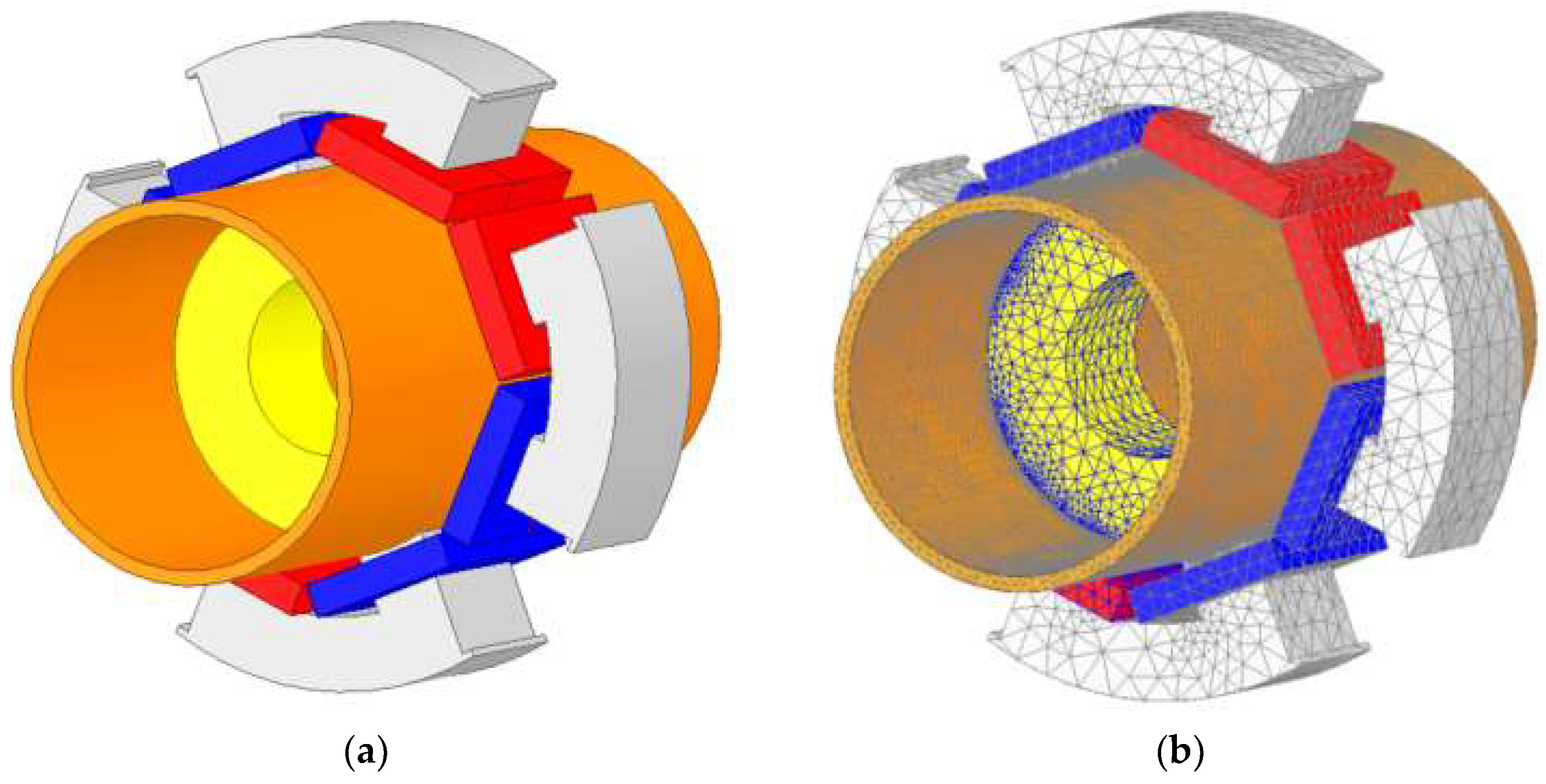
In order to verify the correctness of the above modeling results of the IAMB and further analyze its performance, a 3D FEM model is established for simulation verification. An IAMB prototype is created, and an experimental platform is built for related experiments. Table 1 shows the relevant design parameters.

4.1. 3D FEM Model

Figure 9 shows the 3D FEM model and meshing model established according to the design parameters. After assigning the corresponding material to each element, the performance parameters of the IAMB can be calculated by changing the current of the coil and the position of the rotor during simulation.
Figure 10 shows the magnetic density distribution of the IAMB system and the isolation sleeve when the current of each winding is 1.6 A and the rotor is in the balance position. It can be seen that the axial magnetic leakage in the isolation sleeve is significant but it gradually decreases along the axial direction, which is consistent with the analysis. Due to the superposition of magnetic flux in each direction, the local magnetic density of the isolation sleeve corresponding to the stator tooth edge is relatively large.

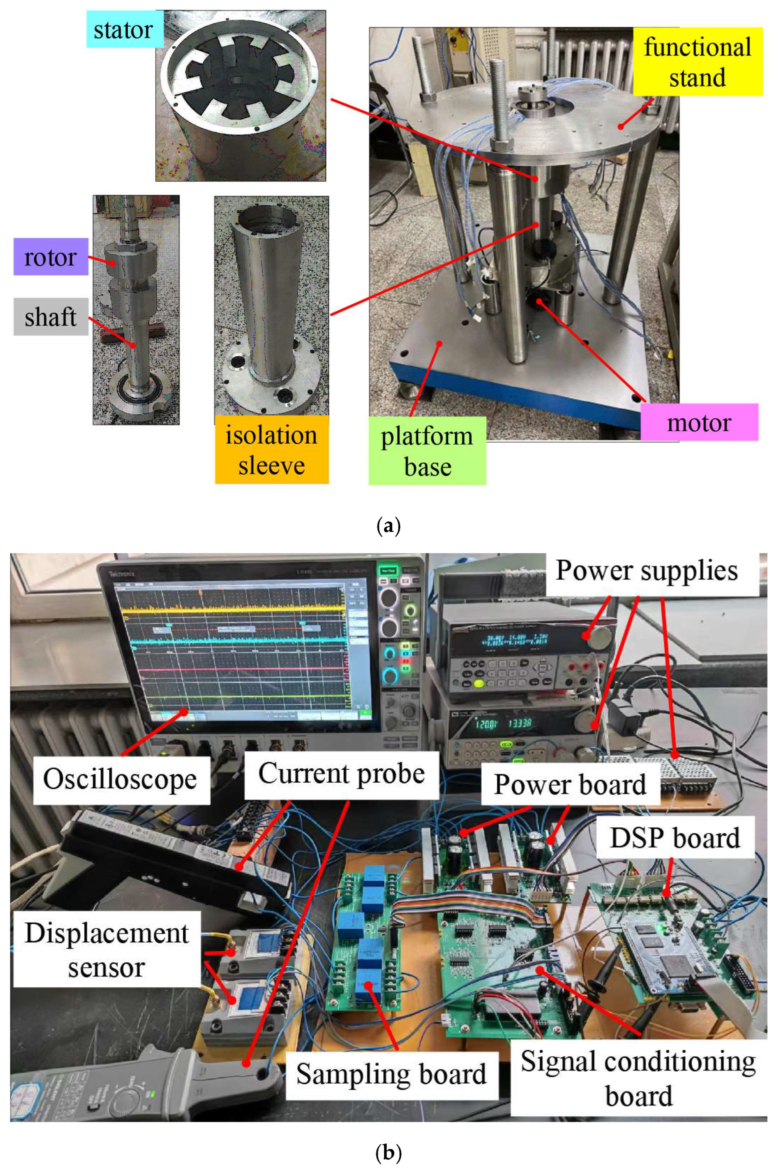
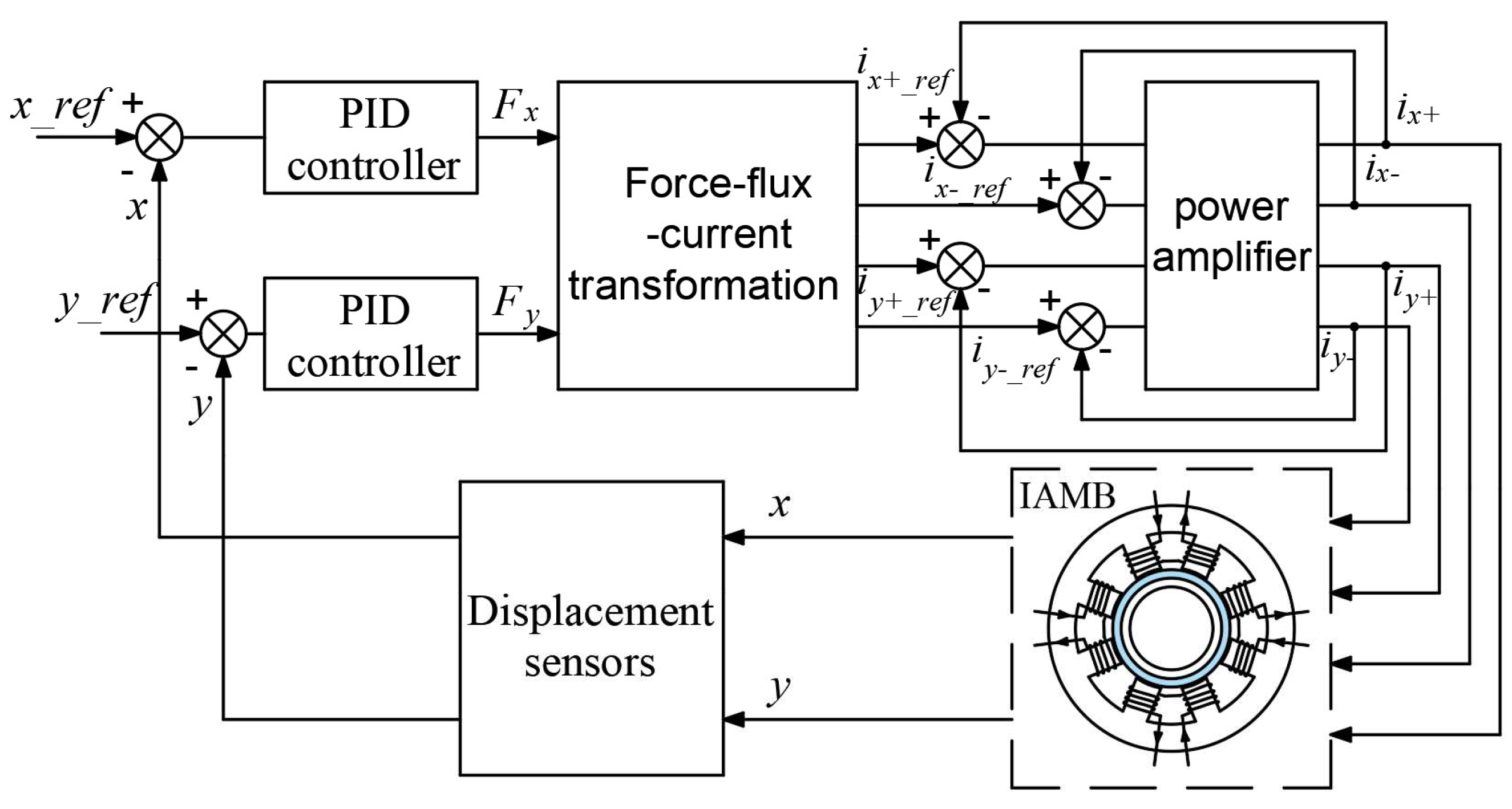
4.2. Experimental Platform and Control System

As shown in Figure 11, the experimental verification is carried out on the IAMB experimental platform, which mainly includes the IAMB operating platform and control system. The operating platform in Figure 11a includes the IAMB, functional stand, motor, and platform base. The IAMB adopts a vertical structure, and the rotor is driven to rotate by the drive motor at the bottom. Hardware such as displacement sensors and force sensors are installed on the functional stand to monitor the rotor displacement and force. In Figure 11b, the hardware control system includes the displacement sensor, sampling board, signal conditioning board, digital signal processing (DSP) board, power board, and power supply. The current and voltage of the coil are input to the sample plate through the cable, sampled and attenuated, and then input to the signal conditioning board. At the same time, the rotor displacement signal and force signal measured by the sensor are input to the signal conditioning board. The signal conditioning board adjusts all signals into 0–3 V voltage signals and inputs them to the DSP board for analog and digital conversion (ADC) and processing. The double closed-loop control calculation of current and displacement is carried out in the DSP board, and an EPWM wave is output to the power board. Finally, the PWM chopper voltage signal is output to the coil through the power board to realize the stable suspension of the rotor.
The control block diagram of the IAMB is shown in Figure 12, in which the system adopts a position current through a double closed-loop control strategy. The displacement sensor monitors the rotor position information (x, y) in real time and transmits it to the controller to compare it with the given position quantity (x_ref, y_ref). Then, the required suspension force is calculated using a proportional-integral-derivative (PID) controller. According to the mathematical model established above, the force-magnetic flux-current transformation is performed to obtain the reference current signal (ix+_ref, ix−_ref, iy+_ref, iy−_ref). After the PWM duty cycle is calculated, the current (ix+, ix, iy+, iy−) of the coil is obtained by switching the power amplifier. The rapid adjustment of the coil current allows the rotor to stably levitate at the equilibrium position.

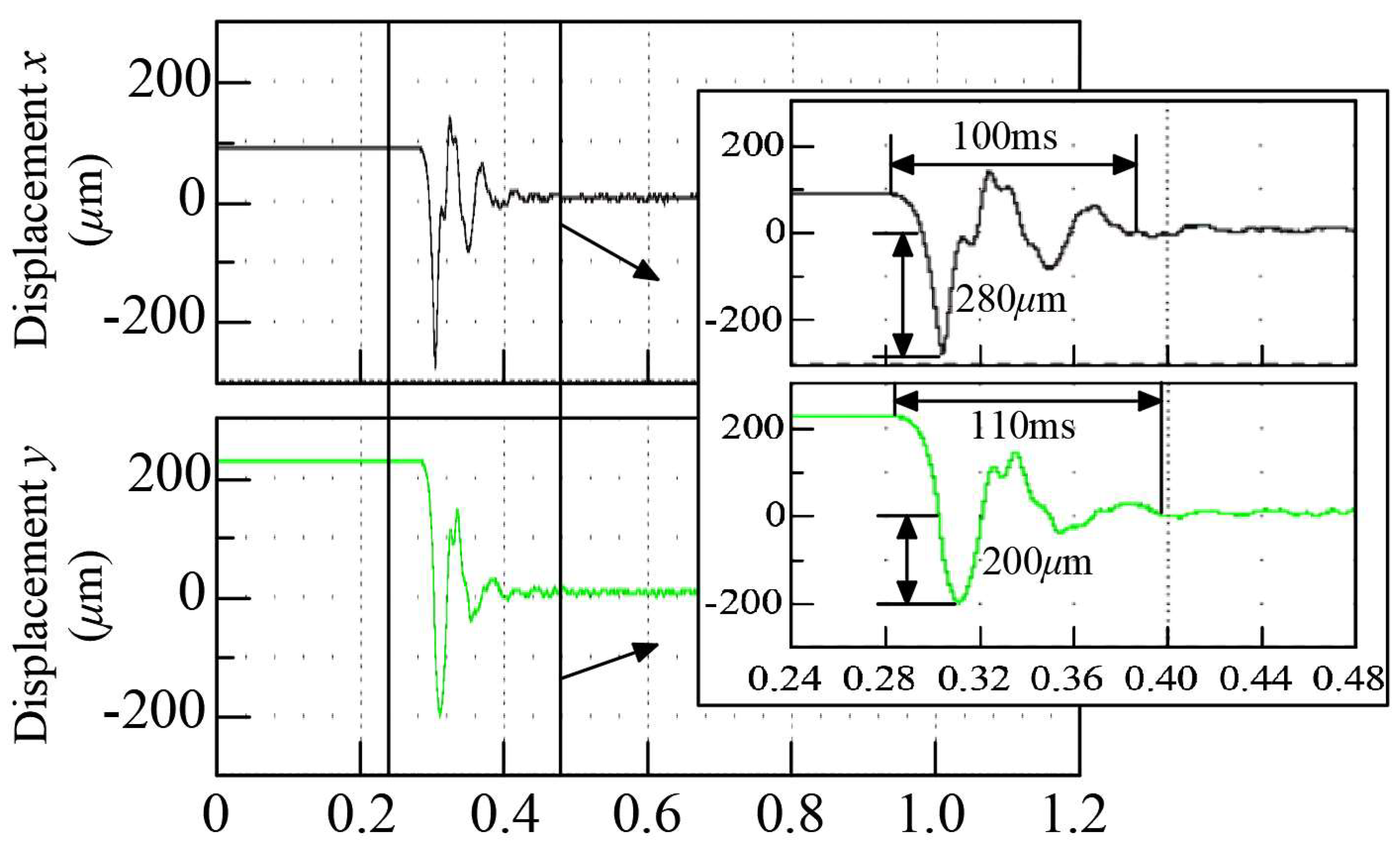
4.3. Suspension Experiment

In order to verify the realizability of the IAMB and the correctness of the established model, suspension control experiments of the IAMB system were carried out. In Figure 13, the experiment waveforms obtained by the suspension control of the control system in Figure 12 are presented. Limited by the protective bearing, the range of motion of the rotor was 0.6 mm. The vibration range of the rotor near the balance position was 10 μm.
When the rotor was suspended, the current in the coil fluctuated near the bias current under the influence of the current ripple and the error of the rotor displacement. When the bias current was 1.6 A, the measured current ripple was 350 mA under the two-level switching power amplifier used in this system. The total current fluctuation was 0.7 A. It can be seen that the system has high control precision and low noise.
The experiment waveforms when the rotor started to suspend are shown in Figure 14. The rotor was stationary at the position (95 μm, 230 μm) before suspension, and the displacement error Δx > 0, Δy > 0. When the control system started to work, the rotor was subjected to forces in the x and y directions. After two rounds of vibration, the rotor quickly and steadily suspended to the equilibrium position. When the start signal came, the transient time of the rotor to the equilibrium position in the x and y directions was 100 ms and 110 ms, respectively, which is slightly longer than that of a traditional AMB. The reason is that the force-current stiffness of the system is reduced because of the isolation sleeve, and there is an eddy current in the isolation sleeve during suspension that makes the suspension force phase lag relative to the current. In order to shorten the transient time, the control parameters with a higher response speed were selected, which resulted in the rotor overshoot of 280 μm in the x direction and 200 μm in the y direction.

4.4. Stiffness Comparison Experiment

4.4.1. Relationship of Force-Current

After completing the stable suspension of the rotor in the equilibrium position, a constant load force is applied to the rotor in the x direction. Then, the controller will adjust the control current in the coils to keep the rotor in the equilibrium position. The relationship between the suspension force and the control current can be obtained by changing the load force several times and recording the corresponding load force and control current.
Figure 15 shows the relationship between the suspension force Fx and the control current ix when the rotor is in the equilibrium position and the load force is applied in the x direction. In the whole current range, the force-current stiffness values obtained through the DMCM, FEM, and experiment are 192.1 N/A, 186.6 N/A, and 180.9 N/A, respectively. Compared with the experimental results, the errors of the DMCM and FEM are 6.2% and 3.2%, respectively.

4.4.2. Relationship of Force-Displacement

To change the equilibrium position of the rotor from the center position to the displacement, change the equilibrium position of the rotor from the center position to the displacement x in the direction of x, and the rotor will levitate steadily. Without the addition of external forces, the control current in the x direction is not 0. Load forces are added to this direction to balance the forces generated by the displacement stiffness. When the control current is 0, record the displacement of the rotor x and the load force Fx. After changing the position of the rotor several times and recording it, the relationship between the suspension force in the x direction and the displacement of the rotor is obtained.
Figure 16 shows the relationship between the displacement x of the rotor in the x direction and the suspension force Fx. The addition of an isolation sleeve makes the force-displacement curve of the system have obvious nonlinearity. Linearity is good in the x range of −0.1–0.1 mm, and the force-displacement stiffness values obtained through the DMCM, FEM, and experiment are 485.1 N/mm, 539.4 N/mm, and 517.5 N/mm, respectively. Compared with the experimental results, the errors of the DMCM and FEM are 6.3% and 4.2%, respectively.
The stiffness comparison experiment verifies that the calculated results of the DMCM are in good agreement with the experimental results.

5. Conclusions

An IAMB, which has a layer of isolation sleeve between the stator and rotor, is a new type of AMB, whose stator rotor can work under different environmental conditions and has a very broad application prospect. In this paper, the magnetic flux path is accurately divided in the isolation sleeve and the air gap inside and outside of it. A piecewise reluctance calculation is carried out for the magnetic circuit of the IAMB along the axial direction, and the DMCM suitable for an IAMB is established considering the edge effect, magnetic leakage effect, and material nonlinearity. The results of the DMCM are compared with those of a 3D finite element method and experiment, and the accuracy of the DMCM is verified. The errors of the calculated force-current stiffness and force-displacement stiffness are 6.2% and 6.3%, respectively. The modeling method used in this paper is not limited to IAMBs but can also be applied to other isolation devices with inconsistent axial structures, such as isolated hybrid magnetic bearings. The modeling method in this paper does not consider the eddy current loss caused by the isolation sleeve, and the subsequent work will focus on this aspect.

Author Contributions

Project administration, R.Z.; writing—original draft, R.Z.; conceptualization, R.Z. and L.S.; methodology, R.Z. and X.S.; investigation, Z.C.; software, C.X.; validation, R.Z. and W.H. All authors have read and agreed to the published version of the manuscript.

Funding

This research received no external funding.

Data Availability Statement

Data are contained within the article.

Conflicts of Interest

The authors declare no conflict of interest.

References

  1. Falkowski, K.; Kurnyta-Mazurek, P.; Szolc, T.; Henzel, M. Radial Magnetic Bearings for Rotor–Shaft Support in Electric Jet Engine. Energies 2022, 15, 3339. [Google Scholar] [CrossRef]
  2. Wang, D.; Wang, N.; Ye, C.; Chen, K. Research on analytical bearing capacity model of active magnetic bearing based on magnetic saturation. IET Electr. Power Appl. 2017, 11, 1548–1557. [Google Scholar] [CrossRef]
  3. Uzhegov, N.; Smirnov, A.; Park, C.H.; Ahn, J.H.; Heikkinen, J.; Pyrhönen, J. Design Aspects of High-Speed Electrical Machines with Active Magnetic Bearings for Compressor Applications. IEEE Trans. Ind. Electron. 2017, 64, 8427–8436. [Google Scholar] [CrossRef]
  4. Smirnov, A.; Uzhegov, N.; Sillanpää, T.; Pyrhönen, J.; Pyrhönen, O. High-Speed Electrical Machine with Active Magnetic Bearing System Optimization. IEEE Trans. Ind. Electron. 2017, 64, 9876–9885. [Google Scholar] [CrossRef]
  5. Le, Y.; Fang, J.; Wang, K. Design and optimization of a radial magnetic bearing for high speed motor with flexible rotor. IEEE Trans. Magn. 2015, 51, 8300313. [Google Scholar]
  6. Wang, X.; Zhang, Y.; Gao, P. Design and Analysis of Second-Order Sliding Mode Controller for Active Magnetic Bearing. Energies 2020, 13, 5965. [Google Scholar] [CrossRef]
  7. Jiang, D.; Li, T.; Hu, Z.; Sun, H. Novel Topologies of power electronics converter as active magnetic bearing drive. IEEE Trans. Ind. Electron. 2020, 67, 950–959. [Google Scholar] [CrossRef]
  8. Sun, Y.; Ho, Y.; Yu, L. Dynamic Stiffnesses of Active Magnetic Thrust Bearing Including Eddy-Current Effects. IEEE Trans. Magn. 2009, 45, 139–149. [Google Scholar] [CrossRef]
  9. Sun, J.; Ju, Z.; Peng, C.; Le, Y.; Ren, H. A novel 4-DOF hybrid magnetic bearing for DGMSCMG. IEEE Trans. Ind. Electron. 2017, 64, 2196–2203. [Google Scholar] [CrossRef]
  10. Hemenway, N.R.; Gjemdal, H.; Severson, E.L. New Three-Pole Combined Radial–Axial Magnetic Bearing for Industrial Bearingless Motor Systems. IEEE Trans. Ind. Appl. 2021, 57, 6754–6764. [Google Scholar] [CrossRef]
  11. Le, Y.; Sun, J.; Han, B. Modeling and Design of 3-DOF Magnetic Bearing for High-Speed Motor Including Eddy-Current Effects and Leakage Effects. IEEE Trans. Ind. Electron. 2016, 63, 3656–3665. [Google Scholar] [CrossRef]
  12. Shakibapour, F.; Rahideh, A.; Mardaneh, M. 2D analytical model for heteropolar active magnetic bearings considering eccentricity. IET Electr. Power Appl. 2018, 12, 614–626. [Google Scholar] [CrossRef]
  13. Hu, Y.; Chen, B.; Zhang, X.; Zhang, F.; Gong, G.; Li, X.; Li, L. Analysis of Electromagnetic Characteristics of 16 Pole Radial Active Magnetic Bearings. In Proceedings of the 22nd International Conference on Electrical Machines and Systems (ICEMS), Harbin, China, 11–14 August 2019; pp. 1–6. [Google Scholar]
  14. Han, B.C.; Zheng, S.Q. Weight-reduction design based on integrated radial-axial magnetic bearing of a large-scale MSCMG for space station application. IEEE Trans. Ind. Electron. 2017, 64, 2205–2214. [Google Scholar] [CrossRef]
  15. Zhu, H.Q.; Ding, S.L.; Jv, J.T. Modeling for three-pole radial hybrid magnetic bearing considering edge effect. Energies 2016, 9, 345. [Google Scholar] [CrossRef]
  16. Yu, C.; Deng, Z.; Mei, L.; Peng, C.; Cao, X.; Chen, S.; Ding, Q. Evaluation Criteria of Material Selection on 3-DOF Hybrid Magnetic Bearing. IEEE Trans. Ind. Appl. 2021, 57, 4733–4744. [Google Scholar] [CrossRef]
  17. Wang, H.; Wu, Z.; Liu, K.; Wei, J.; Hu, H. Modeling and Control Strategies of a Novel Axial Hybrid Magnetic Bearing for Flywheel Energy Storage System. IEEE/ASME Trans. Mechatron. 2022, 27, 3819–3829. [Google Scholar] [CrossRef]
  18. Zhang, W.; Yang, H.; Cheng, L.; Zhu, H. Modeling based on exact segmentation of magnetic field for a centripetal force type-magnetic bearing. IEEE Trans. Ind. Electron. 2020, 67, 7691–7701. [Google Scholar] [CrossRef]
  19. Wu, M.; Zhu, H.; Zhang, H.; Zhang, W. Modeling and Multilevel Design Optimization of an AC–DC Three-Degree-of-Freedom Hybrid Magnetic Bearing. IEEE Trans. Ind. Electron. 2023, 70, 233–242. [Google Scholar] [CrossRef]
  20. Cao, Z.; Huang, Y.; Guo, B.; Peng, F.; Dong, J.; Hemeida, A. A Novel Hybrid Analytical Model of Active Magnetic Bearing Considering Rotor Eccentricity and Local Saturation Effect. IEEE Trans. Ind. Electron. 2022, 69, 7151–7160. [Google Scholar] [CrossRef]
Figure 1. (a) Structure and exploded view of the IAMB. 1: stator; 2: nonmagnetic pressure block; 3: control coils; 4: rotor; 5: shaft; 6: shell; 7: isolation sleeve. (b) Main magnetic flux of the IAMB. (c) Schematic diagram of structural parameters.
Energies 16 08023 g001
Figure 2. Distributed magnetic circuit model.
Energies 16 08023 g002
Figure 3. (a) Axial segment division. (b) Magnetic flux path of radial section in segment 2. (c) Magnetic flux path and equivalent magnetic circuit of the isolation sleeve in one direction.
Energies 16 08023 g003aEnergies 16 08023 g003b
Figure 4. Flow chart of axial leakage reluctance iterative calculation.
Energies 16 08023 g004
Figure 5. Rotor eccentricity diagram.
Energies 16 08023 g005
Figure 6. (a) Division of flux region for air gap 1. (b) Division of flux region for air gap 2.
Energies 16 08023 g006
Figure 7. B–H curves and fitting curves.
Energies 16 08023 g007
Figure 8. The flowchart of iterative computation.
Energies 16 08023 g008
Figure 9. (a) The 3D FEM model of the IAMB. (b) Meshing model.
Energies 16 08023 g009
Figure 10. (a) The flux density field distribution of the IAMB. (b) The flux density field distribution of the isolation sleeve.
Energies 16 08023 g010
Figure 11. (a) Operating platform for IAMB testing. (b) Hardware system of the IAMB.
Energies 16 08023 g011
Figure 12. Suspension control block diagram.
Energies 16 08023 g012
Figure 13. Experimental results during stable suspension.
Energies 16 08023 g013
Figure 14. The experiment waveforms when the rotor started to suspend.
Energies 16 08023 g014
Figure 15. Comparative results of force-current stiffness in the x-axis.
Energies 16 08023 g015
Figure 16. Comparative results of force-displacement stiffness in x-axis.
Energies 16 08023 g016
Table 1. Designed parameters of the IAMB.
SymbolParameterValue
rsOuter radius of the stator87 mm
rsiInner radius of the stator yoke67 mm
xcWidth of the stator pole20 mm
hLength of the stator pole15.7 mm
riOuter radius of the isolation sleeve51.3 mm
rinInner radius of the isolation sleeve47.3 mm
rrOuter radius of the rotor46.8 mm
δiThickness of the isolation sleeve4 mm
δ1Length of air gap 1 when the rotor is not eccentric0.5 mm
δ2Length of air gap 20.03 mm
lAxial length of the stator40 mm
βRadian between a pair of magnetic poles0.393 rad
θRadian of a single pole0.393 rad
αAngle between the center lines of adjacent magnetic poles0.785 rad
I0Bias current1.6 A
NTurn number of the coil180
Disclaimer/Publisher’s Note: The statements, opinions and data contained in all publications are solely those of the individual author(s) and contributor(s) and not of MDPI and/or the editor(s). MDPI and/or the editor(s) disclaim responsibility for any injury to people or property resulting from any ideas, methods, instructions or products referred to in the content.

