Article

Air-Blown Biomass Gasification Process Intensification for Green Hydrogen Production: Modeling and Simulation in Aspen Plus

1
Faculty of Engineering, University of Porto, Rua Dr. Roberto Frias, 4200-465 Porto, Portugal
2
LAETA-INEGI, Associated Laboratory for Energy, Transports and Aeronautics, Institute of Science and Innovation in Mechanical and Industrial Engineering, Rua Dr. Roberto Frias, 4200-465 Porto, Portugal
*
Author to whom correspondence should be addressed.
Energies 2023, 16(23), 7829; https://doi.org/10.3390/en16237829
Submission received: 30 September 2023 / Revised: 15 November 2023 / Accepted: 26 November 2023 / Published: 28 November 2023
(This article belongs to the Special Issue Biomass Gasification Process in Renewable Energy Systems)

Abstract

:
Hydrogen produced sustainably has the potential to be an important energy source in the short term. Biomass gasification is one of the fastest-growing technologies to produce green hydrogen. In this work, an air-blown gasification model was developed in Aspen Plus®, integrating a water–gas shift (WGS) reactor to study green hydrogen production. A sensitivity analysis was performed based on two approaches with the objective of optimizing the WGS reaction. The gasifier is optimized for carbon monoxide production (Case A) or hydrogen production (Case B). A CO2 recycling stream is approached as another intensification process. Results suggested that the Case B approach is more favorable for green hydrogen production, allowing for a 52.5% molar fraction. The introduction of CO2 as an additional gasifying agent showed a negative effect on the H2 molar fraction. A general conclusion can be drawn that the combination of a WGS reactor with an air-blown biomass gasification process allows for attaining 52.5% hydrogen content in syngas with lower steam flow rates than a pure steam gasification process. These results are relevant for the hydrogen economy because they represent reference data for further studies towards the implementation of biomass gasification projects for green hydrogen production.

1. Introduction

The environmental repercussions of energy use are concerning owing to the pollution and global warming they cause. The Paris Agreement was ratified by 194 parties including the European Union in 2015 to mitigate the disastrous results that the release of greenhouse gases into the environment cause.
Biomass gasification is an environmentally friendly method for producing power, biofuels, chemicals, and heat. However, as pointed out by Monteiro and Ferreira [1] there are some obstacles, including tar, impurities, and soot, that prevent its industrial development. They also reveal some research directions to overcome these constraints. “Research should be focused on improving the syngas quality and the economic viability of a biomass gasification plant” [1]. This can be achieved by several means including intensifying techniques for the gasification process to increase the hydrogen yields.
Because of the complexity of biomass as a fuel and biomass gasification as a technology, as well as the influence of various parameters, modeling and simulation are very useful tools for performing biomass gasification studies [2]. Aspen Plus® has been used to develop gasification models, incorporating the main gasification reactions and the main physical aspects of the reactor [3].
Tavares et al. [3] studied the air and steam gasification of forest residues through an Aspen Plus® model based on the minimization of Gibbs free energy. They show that steam gasification increases the hydrogen molar fraction of the syngas in comparison to air-blown gasification. González-Vázquez et al. [4] used Aspen Plus® to create and compare two thermodynamic equilibrium models (stoichiometric and non-stoichiometric). The results revealed that the stoichiometric model agreed with the experimental data better than the non-stoichiometric model. Martins et al. [5] built three biomass gasification process models in Aspen Plus® to predict maximal hydrogen outputs of each gasification process. Their findings revealed that supercritical water gasification is the most suitable gasification technique for hydrogen generation, with hydrogen yields of 0.844 Nm3/kgbiomass. The conventional gasification and plasma gasification methods produced hydrogen yields of 0.828 Nm3/kgbiomass and 0.758 Nm3/kgbiomass, respectively. They also found that under the determined optimal operating conditions, none of the gasification processes are viable. conditions. However, a sensitivity analysis revealed that conventional gasification is viable for steam-to-biomass ratios below 3. Ren et al. [6] developed a simulation model based on Aspen Plus® to study the characteristics and the performance of the steam gasification of refuse-derived fuel (RDF) for hydrogen-rich syngas production. They evaluated the influence of the gasification temperature, steam-to-RDF ratio (S/R), and CaO adsorption temperature on the syngas composition, heating value, and gas yield. Under the gasification temperature of 960 °C and S/R of 1, the hydrogen molar fraction in the syngas increased from 47 to 67% after CaO modification at 650 °C. By raising both S/R and the gasification temperature, higher syngas and hydrogen yields were attained. At a gasification temperature of 960 °C, S/R of 2, and CaO modification temperature of 650 °C, the maximum hydrogen molar percentage (69%), gas production (1.372 m3/kg-RDF), and hydrogen yield (0.935 m3/kg-RDF) were reached. Pitrez et al. [7] developed an improved Aspen Plus model that replicates a high-temperature thermal treatment system for COVID-19 wastes using plasma gasification. The distinctive feature of this model is the inclusion of an additional Gibbs reactor to enhance the calorific value of the syngas. They conclude that the additional Gibbs reactor allows for an increase in the calorific value of the syngas from 4.97 to 5.19 MJ/m3 by increasing the CO and CH4 and decreasing the hydrogen molar fractions. Vikram et al. [8] developed a numerical model for syngas production from woody biomass with steam and CO2 as the gasifying agents using Aspen Plus. The effect of the gasification temperature, reaction temperature, and gasifying agent on H2 and CO concentrations, CO and CO2 conversion, and the H2/CO ratio were parametrically studied. Results revealed that the replacement of H2O by CO2 enhanced the syngas energy content and aided in shaping the H2/CO ratio for downstream synthesis and reduced global greenhouse emissions.
These examples show that the research into the optimization of hydrogen production in a gasification scenario is generally based on a parametric study and gasification improvements through different gasifying agents, catalysts, and especial gasification processes. Intensification processes are scarcely approached, the following being the sole examples. Ersoz et al. [9] settled an integrated model in Aspen Hysis involving a bubbling fluidized bed reactor, a syngas cleaning and conditioning unit (hydrocarbon reforming and water–gas shift processes), and a pressure swing adsorption (PSA) unit to isolate the hydrogen from the syngas stream. The syngas obtained has 38.8% H2 and 1.65% CO. They also realized that a hydrogen purity of 99.999% could be reached at the exit of the PSA unit. Pala et al. [10] developed an Aspen Plus® model of steam biomass gasification coupled to a water–gas shift reactor. They conclude that the H2/CO ratio was adjusted to approximately 2.15, which is above the required ratio for Fischer–Tropsch synthesis. Chu et al. [11] used Aspen Plus® to study the hydrogen production from high-carbon dioxide syngas resorting to a water–gas shift reactor with Cu-Zn and Fe-Cr catalysts. They determined that both catalysts are suitable for syngas water–gas shift reactions with high CO2 concentrations. The maximum value of the H2 increase occurs at 450 °C and is insensible to the CO2 increase. Therefore, more studies on the production of hydrogen-rich syngas via gasification and water–gas shift processes are desired and needed.
This brief state-of-the-art summary allowed us to demonstrate the interest of the scientific community in the biomass gasification process to produce hydrogen. It also shows that the integration of a water–gas shift reactor is scarcely studied. Therefore, in this work, one will show the maximum hydrogen molar fractions obtained from the air-blown gasification process coupled to a water–gas shift reactor with steam injection and carbon dioxide recycling through a modeling study in Aspen Plus®.

2. Materials and Methods

2.1. Biomass Feedstock Selection and Characterization

The biomass employed in this study was forest residues. The rationale for selecting this biomass was Portugal’s abundant supply, as well as to provide an alternative outlet for the forest wastes that contribute to wildfires virtually every year [12]. Table 1 shows the ultimate and proximate analyses of forest residues. The biomass has a moisture content of 11.3% [13].

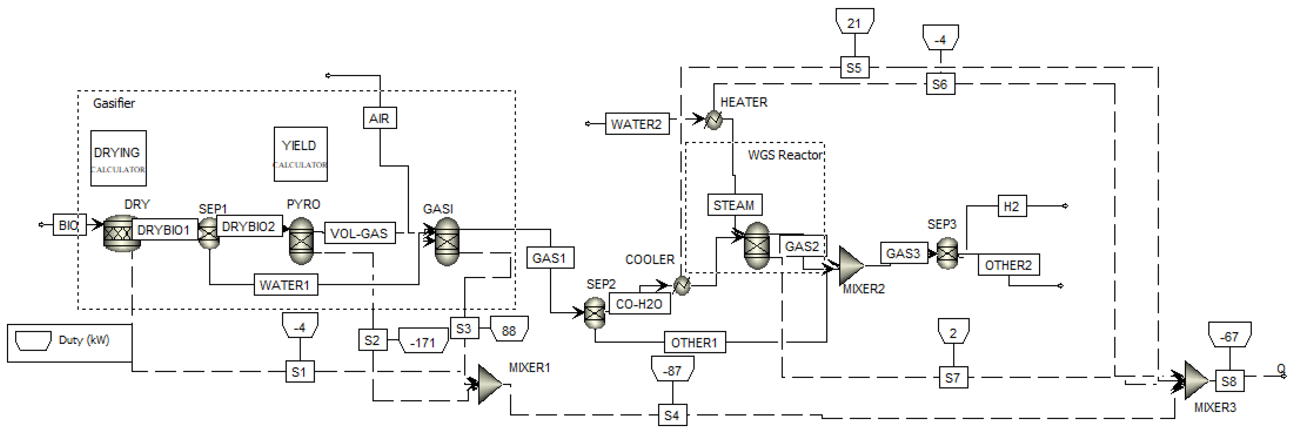
2.2. Aspen Plus Model Development and Validation

Aspen Plus has become one of the most widely used process simulation tools in both academia and industry [14]. In Aspen Plus, there are two basic methodologies for simulating biomass gasification: equilibrium and kinetic. Biomass gasification is generally modeled in Aspen Plus based on the equilibrium approach because it is independent of reactor design and is more applicable if the thermodynamic limitations of the gasification process are the focus with respect to operating conditions and the syngas composition [15], which corresponds to the main goals of the present research. Moreover, a non-stoichiometric modeling technique based on Gibbs free energy minimization is used in this study. The main advantage of this method is that no specific reaction mechanisms or species are involved in the process simulator [2,16]. A detailed description of this approach can be found in several sources [17,18]. It is common to consider the following simplifying conditions in thermodynamic equilibrium modeling [3,8,10,18]:
  • Residence time is long enough for the equilibrium state to be achieved.
  • Homogeneous mixing with uniform pressure and temperature.
  • Kinetic and potential energies are neglected.
  • The gasifier is considered zero-dimensional and adiabatic.
  • Gasifying medium is enough to convert all carbon in the biomass.
  • Nitrogen is considered inert.
  • The produced gas comprises solely CO, H2, CO2, CH4, N2, and H2O.
  • Tar, char, and ash contents are considered negligible.
We provide a specific comment on the last assumption: tars can be ignored because some reactor designs, such as downdraft, are known to produce small tar contents [19]. Moreover, the total yield of chars is assumed to be equal to the fixed carbon and ash contents found by proximate analysis, as shown in Table 1.
The initial stage in building the model was to determine the components that will be employed. One uses solid and gaseous components that are treated by Aspen Plus as unconventional and conventional components in the model, respectively. Because of its heterogeneous character, biomass is classified as a non-conventional component in Aspen Plus. As a result, unless transformed into its basic compounds (C, H2, O2, N2, H2O, etc.), it will not participate in phase or chemical equilibrium calculations [20]. Non-conventional materials are primarily represented by their respective component properties based on their elemental and proximate analyses, as shown in Table 1. For this reason, the gasification model developed comprises a biomass decomposition reactor (RYield) to convert biomass into its conventional compounds. To calculate the enthalpy of biomass and ash, the model HCOALGEN was utilized, and for density, the model DCOALGEN was employed. These models are for coal and coal-derived materials, and they need the attributes ULTANAL, PROXANAL, and SULFANAL [21]. For all thermodynamic characteristics, the Redlich–Kwong–Soave cubic equation of state with the Boston–Mathias alpha function (RKS-BM) was utilized [20].
The developed model for the simulation of the intensified gasification process for hydrogen production comprises two blocks. The block gasifier is responsible for the biomass gasification process, and the block WGS reactor is responsible for the intensification of hydrogen production through a water–gas shift reactor with steam injection. The flowsheet of the model can be seen in Figure 1 and the unit operations used are described in Table 2.
The gasification process is modeled in Aspen Plus® considering three different blocks corresponding to the gasification stages: RStoic (drying), RYield (pyrolysis), and RGibbs (oxidation and reduction).
The entire procedure will take place at 1 bar. An input of 100 kg/s of biomass feedstock at 25 °C is provided to the system. The biomass is routed through a material stream to a unit operation termed RStoic, which simulates its drying at 100 °C. Aspen Plus assumes a molecular weight of 1 g/mol for all the non-conventional components such as biomass [23]. Because water’s molecular weight is 18 g/mol, the biomass molecular ratio will be 1/18 [3]. A DRYING calculator (Fortran subroutine) was utilized in this block to assist in managing the elimination of moisture from the biomass. Afterwards, the steam and dried biomass pass through the DRYBIO1 stream to SEP1. This separator generates two streams: one with just steam (WATER1) that goes to the RGibbs block and another with dried biomass (DRY-BIO2) that travels to the RYield block.
The biomass is then decomposed (pyrolyzed) into gases (H, C, N, and O) and ash in the block RYield at 600 °C. In this block, a Fortran subroutine is also utilized to regulate the devolatilization of biomass by using a calculator (YIELD). The yield composition was obtained from the final biomass analysis. All these additional components are subsequently transported to the RGibbs reactor.
In the RGibbs reactor, the gases combine with an air (21% O2 and 79% N2) stream at 25 °C, the gasifying agent, and steam from the drying process and take part in oxidation and reduction reactions. This reactor models phase and chemical equilibrium by minimizing Gibbs free energy and then estimates the composition of the generated gas. Aside from temperature and pressure, the gasifier requires no more input.
The gas generated in RGibbs (GAS1) is separated by a separator (SEP2), where CO and steam flow via a single stream, CO-H2O, while the remaining components pass through the stream OTHER1. This CO and steam stream is cooled before entering the WGS reactor to the same temperature as the WGS reactor. Steam is also introduced into this reactor after being heated in a heater to 100 °C.
The WGS reactor is modeled using a RGibbs reactor but subjected to a constrained chemical equilibrium [24]. The equilibrium was restricted to the water–gas shift reaction, and a temperature method for this specific reaction was used. CO, H2O, CO2, and H2 are the reactants and products allowed in this reactor. Finally, the products of the WGS reactor are mixed with the lasting gases coming from the gasifier in a mixer (MIXER2), and afterwards they pass through a separator (SEP3). This block generates two streams: one with H2 and another with all the other gases.

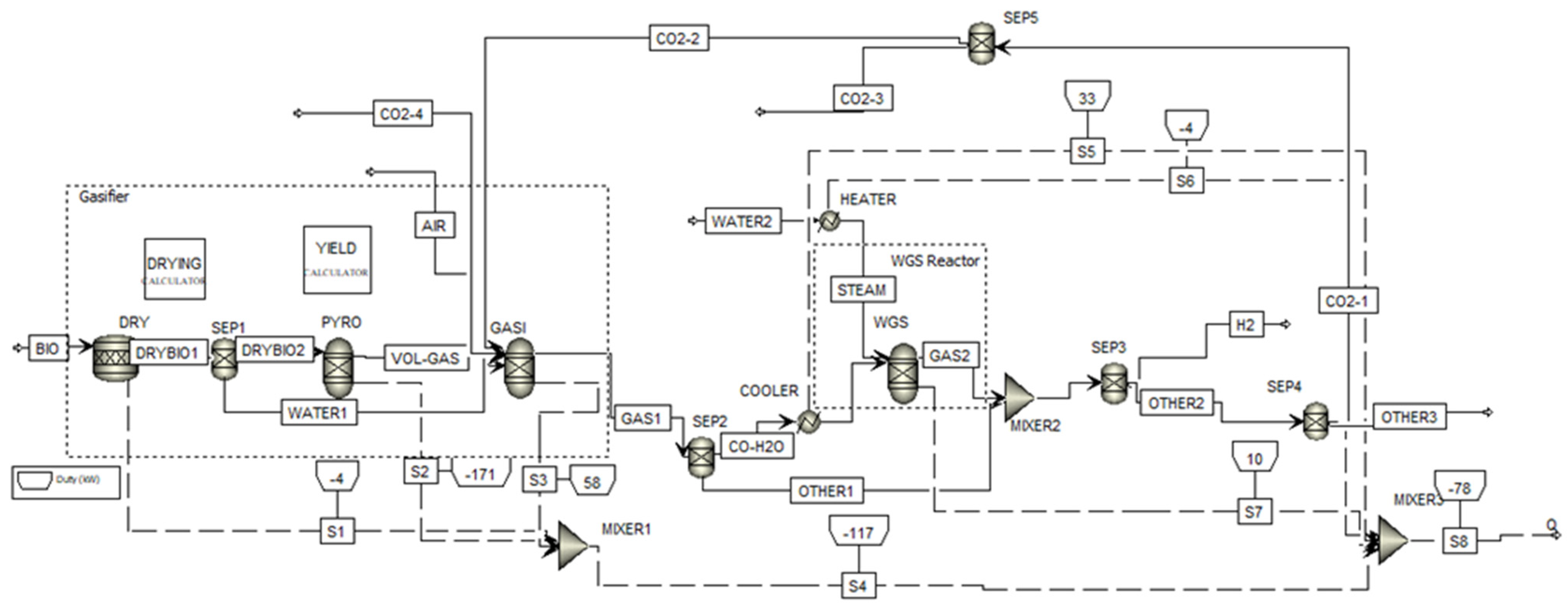
2.2.1. Aspen Plus Model Considering Carbon Dioxide Recycling

Given the large amounts of CO2 present in the produced gas coming from an air-blown biomass gasification process coupled to a WGS reactor, another intensification process was studied. A CO2 recycling stream was implemented in Aspen Plus® by adding to the model of Figure 1 a tear stream, CO2-1, as shown in Figure 2. The rationale behind this hypothesis is the fact that Pandey et al. [25] and Chan et al. [26] demonstrated that CO2 gasification is an effective approach to disposing of this greenhouse gas and may, under certain conditions, increase CO molar fractions in the syngas.
Following the stream OTHER2, an extra separator block (SEP4) is used to generate two streams: one with CO2 and one with all the other elements. Following that, another separator block (SEP5) is installed to regulate the flow of CO2 into the gasifier by mass flow or split fraction.

2.2.2. Gasification Model Validation

The gasifier block model developed was validated against the experimental study of Jayah et al. [27] on rubber wood gasification and the numerical results of Jarungthammachote and Dutta [28] using a pure thermodynamic equilibrium model for the same biomass. The proximate and ultimate analyses of rubber wood are shown in Table 3.
The comparison between the experimental results (for a temperature of 1100 K and an air flow rate of 272 kg/h) of Jayah et al. [27] and the numerical results obtained in this work for the same operating conditions is shown in Table 4. The relative error (Equation (1)) was used to give a better understanding of the results produced by the developed model.
Rel .   Error   ( % )   = Experimental   value     Numerical   value Experimental   value × 100   ( % )
Table 4 also shows the numerical results provided by the stoichiometric equilibrium model of Jarungthammachote and Dutta [28] and the relative error of the experimental results. The inclusion of these numerical literature data has the objective of showing the performance of our model developed in Aspen Plus® based on the minimization of Gibbs free energy, also known as non-stoichiometric equilibrium [29], and the stoichiometric equilibrium model of Jarungthammachote and Dutta [28].
The gasification model developed can be considered validated once it achieves results that agree well with the experimental data of Jayah et al. [27]. It is noticed that the relative error is below 12.2% for the main gas species present in the syngas (Table 4). This can be considered a very good approximation, proving that the model results are trustworthy. Moreover, the relative error between the experimental results and the numerical results of Jarungthammachote and Dutta [28] is below 11.7%, providing a slightly better approach than the non-stoichiometric model developed in this work. This result agrees with González-Vázquez et al. [4].

3. Results and Discussion

The sensitivity analysis performed hereafter is based on two approaches with the objective of optimizing the water–gas shift (WGS) reaction [17]:
CO   + H 2 O H 2 + CO 2   41.2   kJ / mol
Equation (2) represents the reaction of an equimolar mixture of carbon monoxide and steam to produce an equimolar mixture of hydrogen and carbon dioxide. In order to maximize hydrogen production, two approaches will be followed. In the first approach (Case A), the gasifier block is optimized for carbon monoxide production with the perspective of enhancing the forward direction of the water–gas shift reaction. In the second approach (Case B), the gasifier block is optimized for hydrogen production with the perspective of minimizing steam injection.

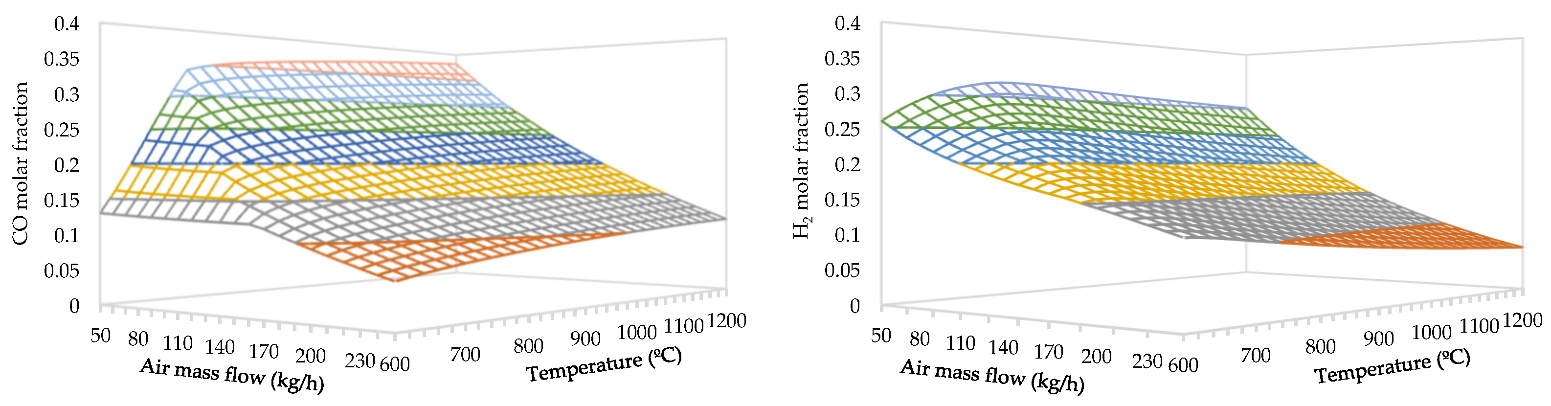
3.1. Effect of Air Flow Rate and Temperature

The effect of the air flow rate and temperature on the syngas composition coming from the gasifier block is parametrically studied herein. The manipulated variables were the air mass flow rate (50–250 kg/h) and the gasifier temperature (600–1200 °C). The results for the CO and H2 molar fractions can be seen in Figure 3.
From Figure 3, it can be seen that the maximum molar fractions of CO and H2 are obtained for different parameters. The maximum molar fraction of CO is obtained at a temperature of 1200 °C and an air flow rate of 50 kg/h, achieving 38.5%. On the other hand, the maximum molar fraction of H2 is obtained at a temperature of 780 °C and an air flow rate of 50 kg/h, attaining 32.4%. It is noticeable that the parameter air flow rate of 50 kg/h is shared between both optimized molar fractions. This air flow rate corresponds to a low equivalence ratio of 0.13, which means that the availability of oxygen for the oxidation reactions is limited. In Case A, the autothermal process is not sustained, requiring an external heat source to attain a high temperature such as 1200 °C. The molar fractions of CO and H2 trends as a function of the air flow rate are corroborated by the available literature results [30,31,32].
Regarding the effect of the temperature, the Le Chatelier principle states that endothermic reactions are favored with an increase in temperature [33]. The whole picture of the main gasification reactions can be found in the cited literature [17,19]. Only the water–gas shift reaction is analyzed here due to the presence of CO in the reactants and H2 in the products. This reaction is exothermic (Equation (2)), which means that the forward direction is enhanced at low temperatures, producing more H2, and the reverse direction is enhanced at high temperatures, producing more CO. This is the rationale explaining the obtained results, which agree with the literature [34,35].

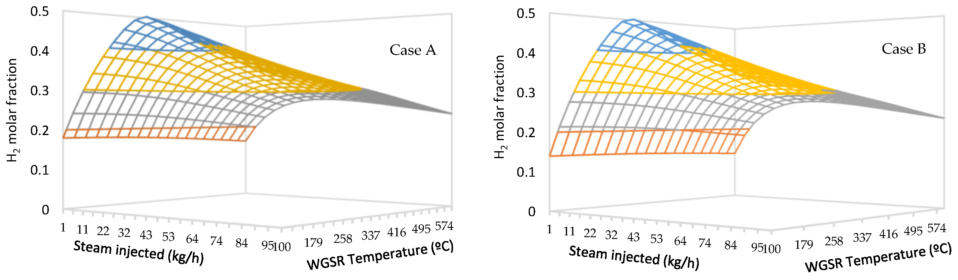
3.2. Effect of The Water–Gas Shift Reactor

With the objective of increasing the hydrogen content in the syngas, a WGS reactor was added after the gasifier block so that CO and steam could react, producing hydrogen and carbon dioxide. The sensitivity analysis made in the WGS Gibbs reactor consisted of adjusting the steam mass flow up to 100 kg/h and the reactor temperature between 100 and 600 °C. Figure 4 depicts the hydrogen molar fraction for Cases A and B.
The similarity of the hydrogen molar fraction behavior for Cases A and B is noticeable. Moreover, nearly the same maximum hydrogen molar fraction (46.8% for Case A and 46.9% for Case B) is achieved for a steam flow rate of 43 kg/h and for a WGS reactor temperature of 100 °C. According to Le Chatelier’s principle, the exothermic nature of the WGS reaction causes the equilibrium constant to fall with temperature (to ~1.0 at 100 °C); thus, high conversions are enhanced by low temperatures [36]. The slight differences between both approaches occur mainly for low (up to around 15 kg/h) steam flow rates and for high steam flow rates above around 80 kg/h. This behavior may be explained by the fact that the presence of steam in quantities larger than the stoichiometric quantity enhances conversion [37]. On the other hand, reaction kinetics take precedence at higher temperatures [37]. Figure 5 depicts hydrogen molar fractions achieved at the gasifier’s exit, the WGS reactor’s outlet, and separator 3’s output for Cases A and B. The latter indicates the combined process’s total hydrogen molar fraction.
Figure 5 demonstrates that the approach of Case B is more favorable for green hydrogen production. It allows for achieving a 52.5% molar fraction thanks to the higher molar fraction of hydrogen at the exit of the gasifier block. Another relevant aspect of this approach is that the steam consumption in the WGS reactor is the same as in Case A.
These results (Case B) are compared to the ones obtained in the steam biomass gasification process of Tavares et al. [3] using the same modeling technique and assumptions as shown in Figure 6.
Figure 6 indicates that the combined process used in this study allows us to obtain greater hydrogen molar percentages at low steam flow rates. The steam gasification method, on the other hand, allows for larger molar percentages of hydrogen using greater quantities of injected steam. These results constitute very important data for further studies, mainly of an economic nature because steam production is an expensive process.

3.3. Effect of Carbon Dioxide Recycle Stream

Considering the large amounts of CO2 in the syngas coming from an air-blown biomass gasification process coupled to a WGS reactor, a CO2 recycling stream was studied in this work. Therefore, the gasifying agent becomes a mixture of air and CO2 in this case study. Considering the feedstock used (forest residues), a gasification plant using a mixture of air and recycled CO2 will become carbon negative. However, the recycle stream implementation in Aspen Plus® presents some challenges in terms of convergence. In this work, a good initial guess was fundamental for the fast convergence of the iterative process of the so-called tear stream. A parametric study was performed to determine the effect of the recycled CO2 on the hydrogen molar fraction resulting from the forest residue gasification. The gasification conditions of Case B (air flow rate of 50 kg/h and gasifier temperature of 780 °C) were set, and the CO2 mass flow was varied up to 60 kg/h. Figure 7 depicts the results.
The results of Figure 7 indicate that the introduction of CO2 has no positive effect on the H2 molar fraction in a forest residue gasification process. Earlier studies have shown that the use of CO2 as the gasifying agent slightly decreases the hydrogen molar fractions [25,38]. This study agrees and confirms those results.

4. Conclusions

This work aimed to study the effects on hydrogen production of integrating a WGS reactor into an air-blown and air-CO2 biomass gasification process by developing a non-stoichiometric equilibrium model in Aspen Plus®. Two approaches were implemented in the air-blown biomass gasification process with the perspective of maximizing hydrogen production and minimizing the amount of steam injected in the water–gas shift reactor. CO2 recycling was also approached from the perspective of this combined process becoming carbon negative. The main results of this study can be summarized as follows:
  • The maximum molar fraction of CO is obtained at a temperature of 1200 °C and an air flow rate of 50 kg/h, achieving 38.5%.
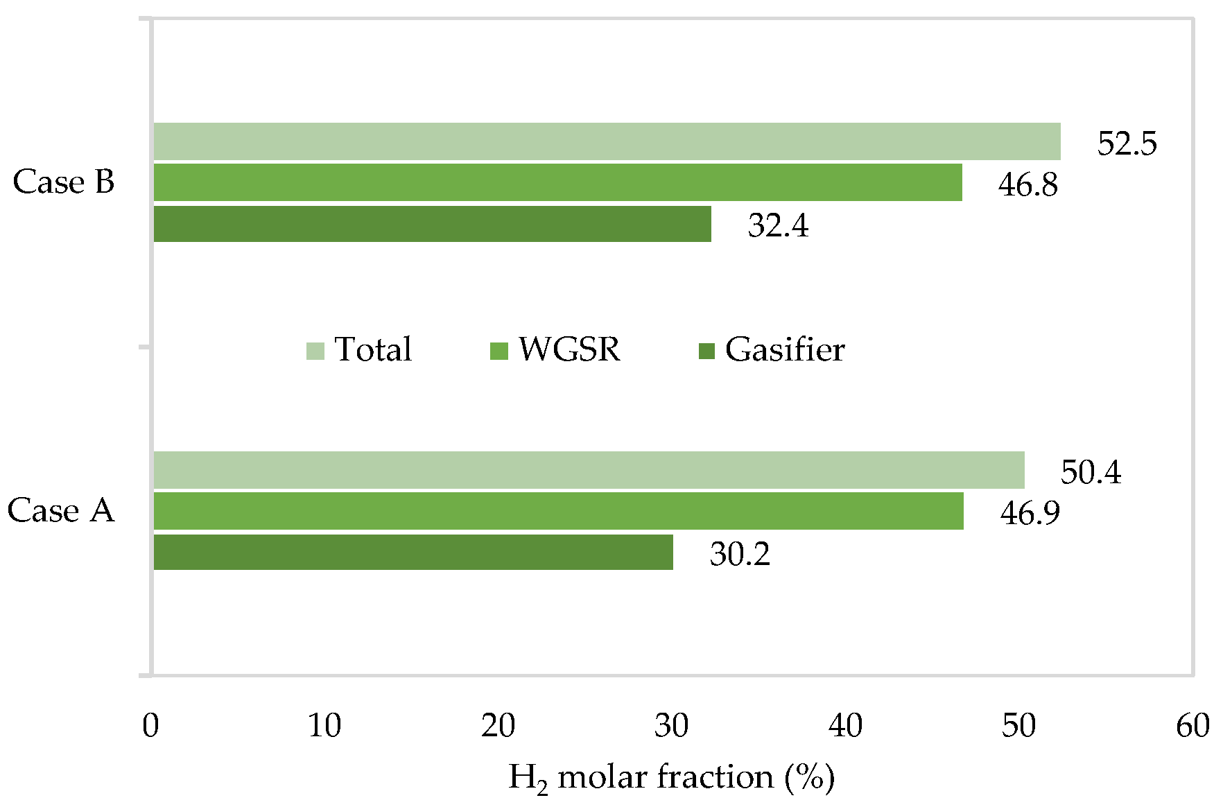
  • The maximum molar fraction of H2 is obtained at a temperature of 780 °C and an air flow rate of 50 kg/h, attaining 32.4%.
  • The Case B approach is more favorable for green hydrogen production, allowing for a 52.5% molar fraction thanks to the higher molar fraction of hydrogen at the exit of the gasifier block, with the same steam consumption in the WGS reactor as in Case A.
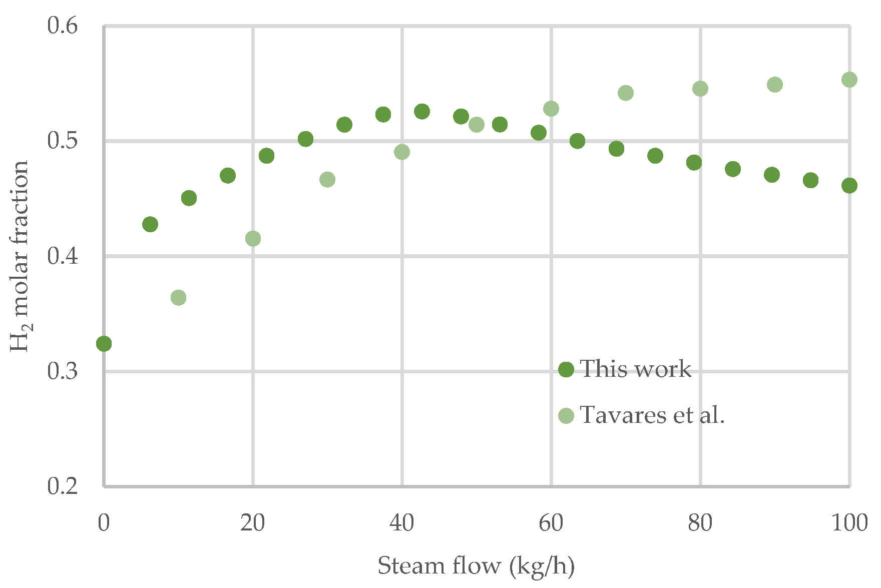
  • The combined process implemented in this study allows for a greater hydrogen molar fraction at lower steam flow rates than a pure steam gasification process.
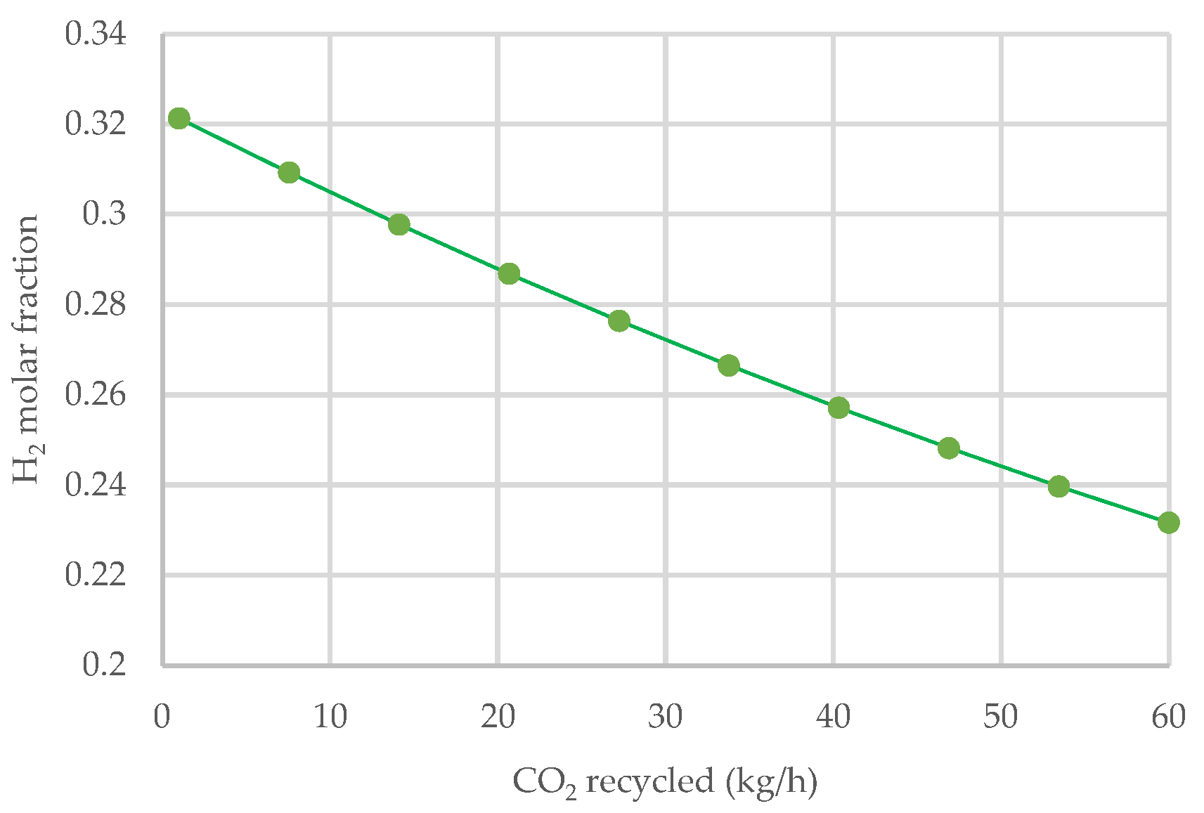
  • The introduction of CO2 as an additional gasifying agent has no positive effect on the H2 molar fraction in a forest residue gasification process.
The main contribution of this work was to prove that the combination of a WGS reactor with an air-blown biomass gasification process allows for attaining 52.5% of hydrogen content in syngas with the minimum steam injection.
These results are remarkably relevant for the scientific community and for the hydrogen economy (industry and political deciders) because they represent reference data for further studies towards the implementation of biomass gasification plants for green hydrogen production.

Author Contributions

Conceptualization, B.N. and E.M.; methodology, B.N.; validation, E.M., A.R. (Ana Ramos) and A.R. (Abel Rouboa); investigation, B.N.; resources, E.M. and A.R. (Abel Rouboa); writing—original draft preparation, B.N.; writing—review and editing, E.M., A.R. (Ana Ramos) and A.R. (Abel Rouboa); supervision, E.M. and A.R. (Ana Ramos); funding acquisition, E.M. All authors have read and agreed to the published version of the manuscript.

Funding

This research is funded by national funds through FCT—Foundation for Science and Technology, I.P., as part of project no. 2022.08625.PTDC; DOI: 10.54499/2022.08625.PTDC and, when eligible, by COMPETE 2020 FEDER funds, under the Scientific Employment Stimulus—Individual Call (CEEC Individual)—2021.03036.CEECIND/CP1680/CT0003.

Data Availability Statement

Data are contained within the article.

Conflicts of Interest

The authors declare no conflict of interest.

References

  1. Monteiro, E.; Ferreira, S. Some Perspectives for the Gasification Process in the Energy Transition World Scenario. Energies 2023, 16, 5543. [Google Scholar] [CrossRef]
  2. Ramos, A.; Monteiro, E.; Rouboa, A. Numerical approaches and comprehensive models for gasification process: A review. Renew. Sustain. Energy Rev. 2019, 110, 188–206. [Google Scholar] [CrossRef]
  3. Tavares, R.; Monteiro, E.; Fouzi, T.; Rouboa, A. Numerical investigation of optimum operating conditions for syngas and hydrogen production from biomass gasification using Aspen Plus. Renew. Energy 2020, 146, 1309–1314. [Google Scholar] [CrossRef]
  4. González-Vázquez, M.P.; Rubiera, F.; Pevida, C.; Pio, D.T.; Tarelho, L.A.C. Thermodynamic Analysis of Biomass Gasification Using Aspen Plus: Comparison of Stoichiometric and Non-Stoichiometric Models. Energies 2021, 14, 189. [Google Scholar] [CrossRef]
  5. Martins, A.H.; Rouboa, A.; Monteiro, E. On the green hydrogen production through gasification processes: A techno-economic approach. J. Clean. Prod. 2023, 383, 135476. [Google Scholar] [CrossRef]
  6. Ren, R.; Wang, H.; You, C. Steam Gasification of Refuse-Derived Fuel with CaO Modification for Hydrogen-Rich Syngas Production. Energies 2022, 15, 8279. [Google Scholar] [CrossRef]
  7. Pitrez, P.; Monteiro, E.; Rouboa, A. Numerical analysis of plasma gasification of hazardous waste using Aspen Plus. Energy Rep. 2023, 9, 418–426. [Google Scholar] [CrossRef]
  8. Vikram, S.; Rosha, P.; Kumar, S.; Mahajani, S. Thermodynamic analysis and parametric optimization of steam-CO2 based biomass gasification system using Aspen Plus. Energy 2022, 241, 122854. [Google Scholar] [CrossRef]
  9. Ersoz, A.; DurakÇetin, Y.; Sarioglan, A.; Turan, A.Z.; Mert, M.S.; Yuksel, F.; Figen, H.E.; Guldal, N.O.; Karaismailoglu, M.; Baykara, S.Z. Investigation of a novel & integrated simulation model for hydrogen production from lignocellulosic biomass. Int. J. Hydrogen Energy 2018, 43, 1081–1093. [Google Scholar]
  10. Pala, L.P.R.; Wang, Q.; Kolb, G.; Hessel, V. Steam gasification of biomass with subsequent syngas adjustment using shift reaction for syngas production: An Aspen Plus model. Renew. Energy 2017, 101, 484–492. [Google Scholar] [CrossRef]
  11. Chu, H.; Li, Q.; Meng, A.; Zhang, Y. Investigation of hydrogen production from model bio-syngas with high CO2 content by water-gas shift reaction. Int. J. Hydrogen Energy 2015, 40, 4092–4100. [Google Scholar] [CrossRef]
  12. Ferreira, S.; Monteiro, E.; Brito, P.; Vilarinho, C. Biomass resources in Portugal: Current status and prospects. Renew. Sust. Energy Rev. 2017, 78, 1221–1235. [Google Scholar] [CrossRef]
  13. Silva, V.; Monteiro, E.; Couto, N.; Brito, P.; Rouboa, A. Analysis of syngas quality from Portuguese biomasses: An experimental and numerical study. Energy Fuels 2014, 28, 5766–5777. [Google Scholar] [CrossRef]
  14. Mutlu, O.Ç.; Zeng, T. Challenges and Opportunities of Modeling Biomass Gasification in Aspen Plus: A Review. Chem. Eng. Technol. 2020, 43, 1674–1689. [Google Scholar] [CrossRef]
  15. De, S.; Agarwal, A.K.; Moholkar, V.S.; Thallada, B. Coal and Biomass Gasification: Recent Advances and Future Challenges; Springer Nature: Singapore, 2018. [Google Scholar]
  16. Puig-Arnavat, M.; Bruno, J.C.; Coronas, A. Review and analysis of biomass gasification models. Renew. Sust. Energy Rev. 2010, 14, 2841–2851. [Google Scholar] [CrossRef]
  17. Basu, P. Biomass Gasification, Pyrolysis, and Torrefaction: Practical Design and Theory, 3rd ed.; Academic Press, Elsevier: Amsterdam, The Netherlands, 2018. [Google Scholar]
  18. La Villetta, M.; Costa, M.; Massarotti, N. Modelling approaches to biomass gasification: A review with emphasis on the stoichiometric method. Renew. Sust. Energ. Rev. 2017, 74, 71–88. [Google Scholar] [CrossRef]
  19. McKendry, P. Energy production from biomass (part 3): Gasification technologies. Bioresour. Technol. 2002, 83, 55–63. [Google Scholar] [CrossRef] [PubMed]
  20. Al Malah, K.I.M. Aspen Plus: Chemical Engineering Applications; John Wiley & Sons: New York, NY, USA, 2017. [Google Scholar]
  21. Aspen Technology Inc. Aspen Plus User Guide; Version 10.2; Aspen Technology Inc.: Cambridge, MA, USA, 2000. [Google Scholar]
  22. Towler, G.P.; Sinnott, R.K. ; Chemical Engineering Design: Principles, Practice, and Economics of Plant and Process Design, 2nd ed.; Butterworth-Heinemann: Oxford, UK; Waltham, MA, USA, 2013. [Google Scholar]
  23. Aspen Technology Inc. Getting Started Modeling Processes with Solids; Version 8.4; Aspen Technology, Inc.: Bedford, MA, USA, 2013. [Google Scholar]
  24. Mendiburu, A.Z.; Carvalho, J.A.; Rolando Zanzi, R.; Coronado, C.R.; Silveira, J.L. Thermochemical equilibrium modeling of a biomass downdraft gasifier: Constrained and unconstrained non-stoichiometric models. Energy 2014, 71, 624–637. [Google Scholar] [CrossRef]
  25. Pandey, B.; Sheth, P.N.; Prajapati, Y.K. Air-CO2 and oxygen-enriched air-CO2 biomass gasification in an autothermal downdraft gasifier: Experimental studies. Energy Convers. Manag. 2022, 270, 116216. [Google Scholar] [CrossRef]
  26. Chan, Y.H.; Rahman, S.N.F.S.A.; Lahuri, H.M.; Khalid, A. Recent progress on CO-rich syngas production via CO2 gasification of various wastes: A critical review on efficiency, challenges and outlook. Environ. Pollut. 2021, 278, 116843. [Google Scholar] [CrossRef]
  27. Jayah, T.H.; Aye, L.; Fuller, R.J.; Stewart, D.F. Computer simulation of a downdraft wood gasifier for tea drying. Biomass Bioenergy 2003, 25, 459–469. [Google Scholar] [CrossRef]
  28. Jarungthammachote, S.; Dutta, A. Thermodynamic equilibrium model and second law analysis of a downdraft waste gasifier. Energy 2007, 32, 1660–1669. [Google Scholar] [CrossRef]
  29. Ferreira, S.; Monteiro, E.; Brito, P.; Vilarinho, C. A Holistic Review on Biomass Gasification Modified Equilibrium Models. Energies 2019, 12, 160. [Google Scholar] [CrossRef]
  30. Ismail, T.M.; Monteiro, E.; Ramos, A.; El-Salam, M.A.; Rouboa, A. An Eulerian model for forest residues gasification in a plasma gasifier. Energy 2019, 182, 1069–1083. [Google Scholar] [CrossRef]
  31. Kangas, P.; Hannula, I.; Koukkari, P.; Hupa, M. Modelling super-equilibrium in biomass gasification with the constrained Gibbs energy method. Fuel 2014, 129, 631–653. [Google Scholar] [CrossRef]
  32. Ferreira, S.; Monteiro, E.; Calado, L.; Silva, V.; Brito, P.; Vilarinho, C. Experimental and modeling analysis of brewers’ spent grains gasification in a downdraft reactor. Energies 2019, 12, 4413. [Google Scholar] [CrossRef]
  33. Ferreira, S.; Monteiro, E.; Brito, P.; Vilarinho, C. Experimental Analysis of Brewers’ Spent Grains Steam Gasification in an Allothermal Batch Reactor. Energies 2019, 12, 912. [Google Scholar] [CrossRef]
  34. Ahmad, A.A.; Zawawi, N.A.; Kasim, F.H.; Inayat, A.; Khasri, A. Assessing the gasification performance of biomass: A review on biomass gasification process conditions, optimization and economic evaluation. Renew. Sustain. Energy Rev. 2016, 53, 1333–1347. [Google Scholar] [CrossRef]
  35. Thomson, R.; Kwong, P.; Ahmad, E.; Nigam, K.D.P. Clean syngas from small commercial biomass gasifiers; a review of gasifier development, recent advances and performance evaluation. Int. J. Hydrogen Energy 2020, 45, 21087–21111. [Google Scholar] [CrossRef]
  36. Haryanto, A.; Fernando, S.D.; Filip, S.D.; Steele, P.H.; Pordesimo, L.; Adhikari, S. Hydrogen Production through the Water−Gas Shift Reaction: Thermodynamic Equilibrium versus Experimental Results over Supported Ni Catalysts. Energy Fuels 2009, 23, 3097–3102. [Google Scholar] [CrossRef]
  37. Idriss, H.; Scott, M.; Subramani, V. Introduction to hydrogen and its properties. In Compendium of Hydrogen Energy; Subramani, V., Basile, A., Veziroğlu, T.N., Eds.; Woodhead Publishing Series in Energy; Woodhead Publishing: Sawston, UK, 2015; pp. 3–19. [Google Scholar]
  38. Couto, N.; Silva, V.; Monteiro, E.; Rouboa, A.; Brito, P. An experimental and numerical study on the Miscanthus gasification by using a pilot scale gasifier. Renew. Energy 2017, 109, 248–261. [Google Scholar] [CrossRef]
Figure 1. Flowchart of gasification process coupled to a water–gas shift reactor.
Energies 16 07829 g001
Figure 2. Flowsheet with carbon dioxide recycling stream.
Energies 16 07829 g002
Figure 3. Carbon monoxide and hydrogen molar fractions as a function of the air mass flow rate and temperature.
Energies 16 07829 g003
Figure 4. Variation in hydrogen molar fraction with WGSR temperature and steam injection.
Energies 16 07829 g004
Figure 5. Hydrogen molar fractions at the exit of the gasifier, WGS reactor, and total.
Energies 16 07829 g005
Figure 6. Hydrogen molar fraction comparison for the steam gasification and combined process implemented in this work [3].
Energies 16 07829 g006
Figure 7. Hydrogen molar fraction as a function of carbon dioxide recycled.
Energies 16 07829 g007
Table 1. Proximate and ultimate analysis of forest residues [13].
Proximate Analysis (wt.%. d.b.)Ultimate Analysis (wt.%, d.b.)
Volatile matter79.8C43.0
Fixed carbon20.0H5.0
Ash0.2O49.6
N2.4
Table 2. Aspen Plus reactor features [21,22].
Unit OperationModelFeatures
Yield reactor RYield (PYRO) Yield reactors are especially useful for modeling streams with pseudo components, solids with a particle size dispersion, or processes that create small quantities of various by-products. The yield shift reactor overcomes some of the disadvantages of existing reactor models by allowing the designer to select a yield pattern.
Conversion reactor RStoic
(DRY)
A conversion or stoichiometric reactor requires both a reaction stoichiometry and an extent of reaction, which is commonly described as the extent of a limiting reagent’s conversion. It can be used when the reaction kinetics are unknown or when it is known that the process will persist to complete conversion because no reaction kinetics information is required.
Gibbs reactorRGibbs (GASI, WGS)The Gibbs reactor, subject to the mass balance constraint, resolves the entire reaction and phase equilibrium of all species in the component list by minimizing the Gibbs free energy. A Gibbs reactor can be configured with constraints such as a specified conversion of one species or a temperature approach to equilibrium.
Stream mixing Mixer (MIXER 1, 2) Mixers join several streams (mass, heat, or work) into a single stream.
Component splitter Sep
(SEP 1, 2)
The separator separates the entering stream components into several exit streams based on the identified flows or split fractions.
HeaterHeater
(HEATER)
Heaters are used to heat or cool a stream.
Table 3. Proximate and ultimate analyses of rubber wood [27].
Proximate Analysis (wt.%. d.b.)Ultimate Analysis (wt.%, d.b.)
Volatile matter80.1C50.6
Fixed carbon19.2H6.5
Ash0.7O42.0
N0.2
Table 4. Comparison between model and literature results.
Gas SpeciesExperimental [26] Numerical [27]Aspen Plus Model Rel. Error (%) (Exp/Num) Rel. Error (%)
(Exp/Aspen Plus)
H217.018.0415.78−6.12−7.2
CO18.417.8620.642.9312.2
CO210.611.849.72−11.7−8.3
N252.752.1553.861.042.2
Disclaimer/Publisher’s Note: The statements, opinions and data contained in all publications are solely those of the individual author(s) and contributor(s) and not of MDPI and/or the editor(s). MDPI and/or the editor(s) disclaim responsibility for any injury to people or property resulting from any ideas, methods, instructions or products referred to in the content.

