Article

Numerical Investigations of Synthetic Jet Control Effects on Iced Airfoils

National Key Laboratory of Science and Technology on Rotorcraft Aeromechanics, Nanjing University of Aeronautics and Astronautics, Nanjing 210016, China
*
Author to whom correspondence should be addressed.
Energies 2023, 16(22), 7487; https://doi.org/10.3390/en16227487
Submission received: 21 September 2023 / Revised: 2 November 2023 / Accepted: 6 November 2023 / Published: 8 November 2023

Abstract

:
Based on the numerical method, the effects of synthetic jet control (SJC) on the aerodynamic characteristics of iced airfoils are systematically analyzed for the first time. First, an analysis method for the airfoil flowfield under SJC in icing conditions is developed, which contains the CFD method, the icing prediction method, and the boundary conditions of the synthetic jet. Then, the variation in the aerodynamic characteristics of different iced airfoils under the SJC are analyzed, and the flow separation near the ice shape is discussed in detail. Finally, parameters, such as the jet position and angle, are quantified, and conclusions are obtained. The synthetic jet can reduce the separation area on the upper surface induced by the ice accretion. When the energy of the jet is sufficient, it interacts with the mainstream, reducing the separation vortex downstream of the jet orifice and greatly improving the aerodynamic characteristics of the iced airfoil. These results provide valuable insights for the application of synthetic jet technology in mitigating the adverse effects of ice accretion on the airfoil’s aerodynamic characteristics.

1. Introduction

The ice problem is a critical component that limits the safe flight envelope of aircraft [1]. Ice accretion on lifting surfaces, such as wings and rotor blades, may occur when aircraft operate in icing conditions, and the aerodynamic shape can be degraded [2,3]. As a result, extensive research has been conducted in the field of aircraft anti/de-icing technology.
The development of anti/de-icing techniques has made significant progress and includes chemical, thermal, mechanical, etc. [4,5,6]. However, after the icing detection system detects icing, activating the anti-icing and de-icing system may not immediately remove the surface ice. Complete melting of the ice still requires a process, meaning ice formation will be sustained on the surface for a period of time. Under certain icing conditions, due to the periodic operation of the anti-icing system, small ice particles are prone to form on the leading edge surface of the rotor. Additionally, due to the residual overflow water that has not completely evaporated, it often forms ice ridges downstream of the heating area [7].
In the situations mentioned above, ice accretion will still affect the aerodynamic characteristics of the lifting surface, even with the anti/de-icing systems turned on. It also is a blind spot in the research of the anti/de-icing problem. Relevant studies have shown that active flow control technology is an effective means to improve the aerodynamic characteristics of airfoils and suppress flow separation [8,9,10]. With its zero-mass jet characteristics, synthetic jet technology has apparent advantages in improving the aerodynamic characteristics of airfoils and wings [11,12]. Seifert [13] carried out the active flow control test of the NACA0015 airfoil, and the test proved that the synthetic jet has the ability to suppress airfoil stall. Gilarranz [14] conducted a single synthetic jet actuator on the wing aerodynamic performance control test and found that the synthetic jet can effectively improve the airfoil stall angle of attack (AoA). Lee [15] conducted the flow separation control experiment of the jet array on an inclined plate. He [16] studied the influence of the jet pressure and velocity on the adhesion capability of the jet for airfoil aerodynamics. Singh [17] examined the flow separation control with the action of a hybrid jet (the combination of synthetic and continuous jets) over a NACA23012 airfoil. Ma [18] analyzed the parameters of the aerodynamic characteristics of the CFJ airfoil, and the optimal control parameters for aerodynamic characteristics were found. These studies have proved that the synthetic jet is an effective means to control the flow separation of the airfoil and suppress stall [11,19].
At the same time, the ability of synthetic jets to improve aerodynamic characteristics and suppress airflow separation has tremendous potential for active flow control in iced lifting surfaces. However, there are no publicly available publications on the analysis of the control effect of synthetic jets on the aerodynamic characteristics of iced airfoils. In addition, synthetic jet technology has also found new applications in the field of the aircraft icing problem [20,21,22]. Therefore, it will have important academic and engineering value to explore and carry out research on active flow control of iced airfoils based on synthetic jets.
Based on the previous work and the Chinese Laboratory of Rotorcraft Navier–Stokes (CLORNS) code [23,24], an analysis method for airfoil flowfield with synthetic jets in icing conditions is developed, which contains several modules, such as the flowfield solution method, the icing prediction method, and the boundary conditions of synthetic jets. The main objective of the present work is focused on developing a better understanding of the influence mechanism of synthetic jets on the aerodynamic characteristics of iced airfoils. As the main study subject, the aerodynamic characteristics of the NACA23012 airfoil with different ice shapes are calculated and analyzed (the flow is compressible and turbulent), and the flow separation around the ice particles is detailed. Then, the effects of the control parameters, such as the jet excitation frequency, jet position, jet angle, and momentum coefficient, on the aerodynamic characteristics of the iced airfoil are calculated and analyzed systematically.
The novelty of the paper is hinged upon our claim that this is one, if not the first, of a systematic study on the effects of synthetic jet parameters on the aerodynamic characteristics of iced airfoils.

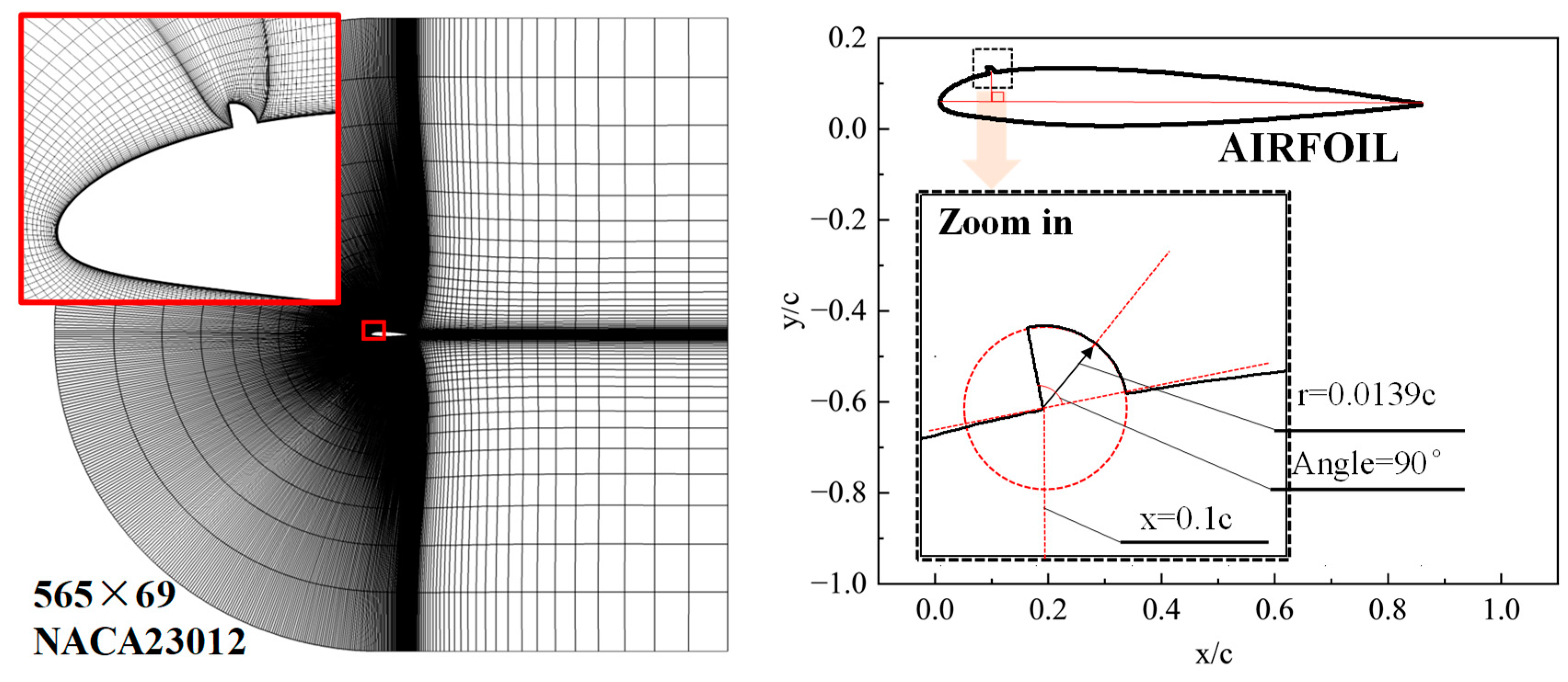
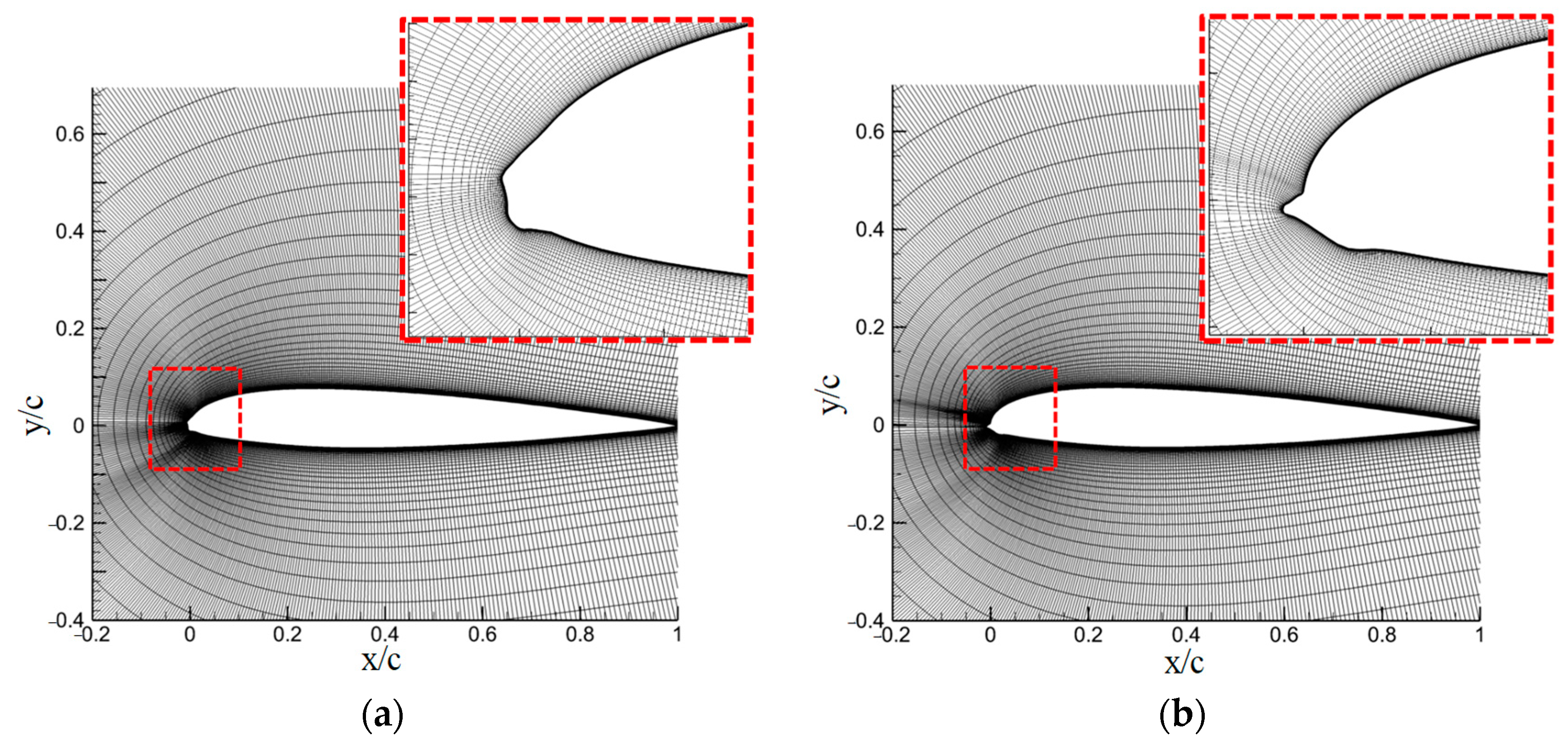
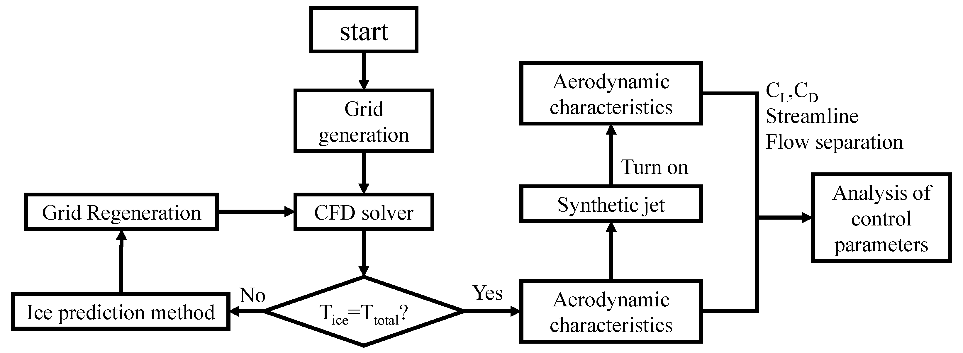
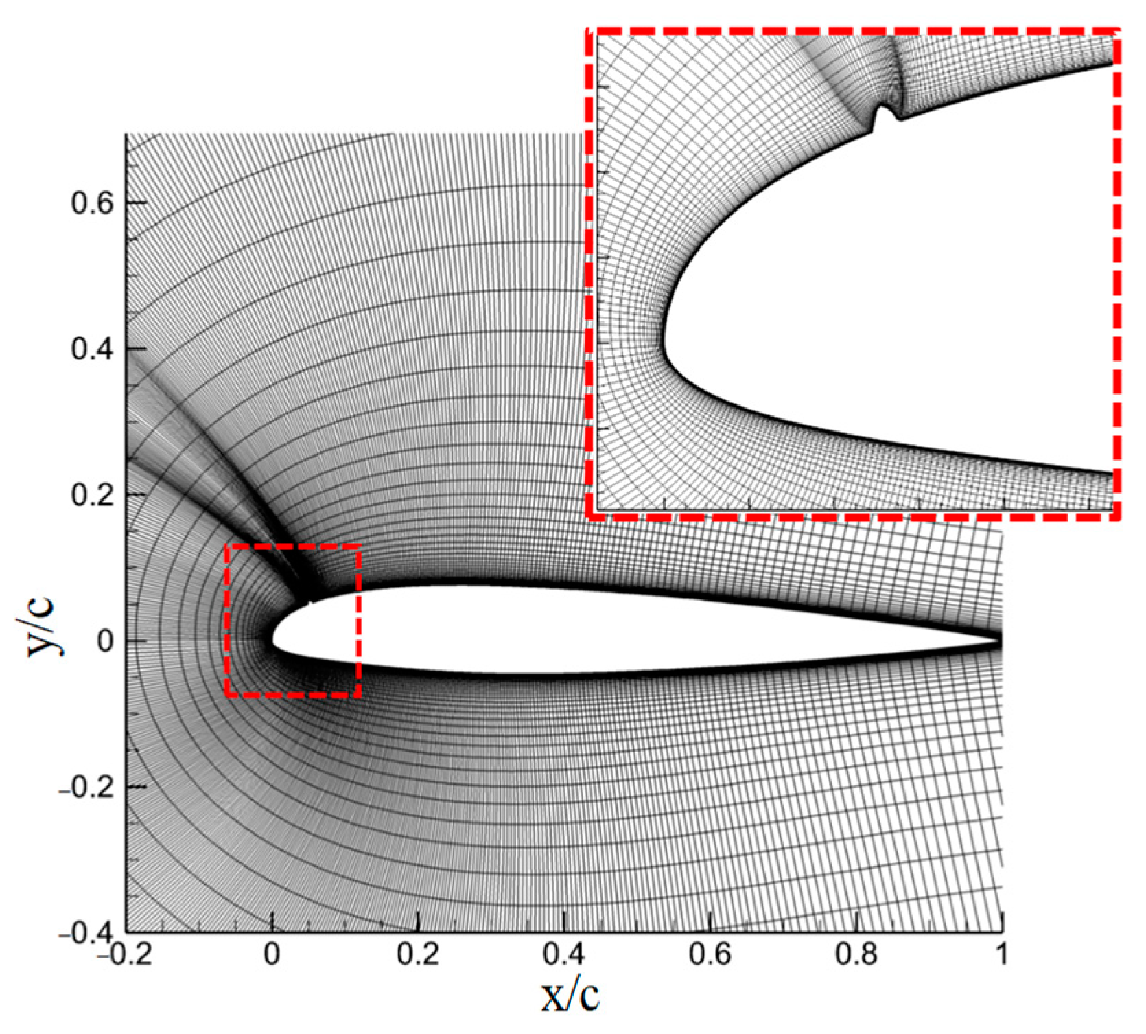
2. Numerical Methods

The proposed numerical simulation approach for the flow control effect of the airfoil via the synthetic jets in icing conditions consists of several modules, including (1) the CFD solver considering the synthetic jet boundary conditions, (2) the numerical simulation method for ice accretion on airfoil, and (3) the grid regeneration for the iced airfoil. If the variation in surface shape is large enough to affect the flowfield, the CFD solver should be invoked to compute the new flowfield around the iced airfoil. The interval time of coupling the CFD solver with the icing model is one third of the total icing time in this paper. The main analytical procedure of the flow control effect of the airfoil via the synthetic jets in icing conditions is illustrated in Figure 1.

2.1. Flowfield Solution Method

The CLORNS code is employed to predict the airfoil flowfield, and the governing equations in integral form are described as:
t W d Ω + S ( F F ν ) n d s = 0
In the code, three alternative spatial discretization schemes are applied in the code, including a second-order central difference scheme, a third-order Roe–MUSCL scheme, and a fifth-order WENO–Roe scheme. The dual time-stepping approach is adopted, and the implicit lower–upper symmetric Gauss–Seidel (LU-SGS) method is employed in pseudo-temporal iteration. To obtain a more reliable iced airfoil flowfield, a low dissipation and shock-capturing TENO (targeted essentially non-oscillatory) scheme [25,26] is developed and applied. The S–A turbulence model is adopted.

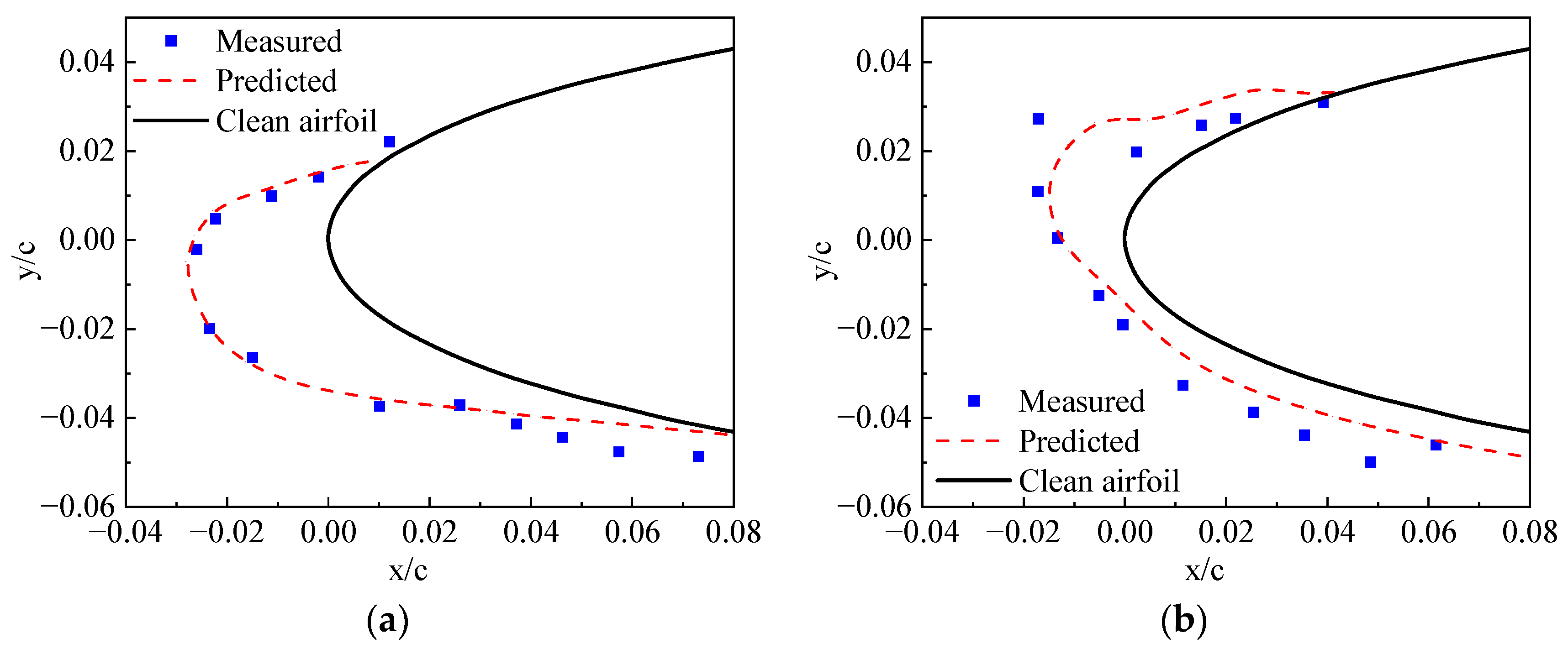
2.2. Icing Prediction Method

In the icing prediction method, the following assumptions are made:
(1)
The droplets are simplified to be spheres with a median volumetric diameter and the physical parameters of droplets are assumed to be constant.
(2)
There is no heat and mass transfer in the movement of droplets before they impinge on the blade.
(3)
After the droplets impinge onto the wing surface, they do not bounce and splash.
(4)
The forces imposed on water droplets only involve the drag force, buoyancy, and gravity. The other unsteady forces are negligible.
(5)
Water droplets which impinge on a unit become a thin, continuous film of water which covers the blade and ice surface.
(6)
The ice grows in the normal direction to the surface.
Based on those assumptions, the Eulerian method is applied for the simulation of the water droplet field around the rotor. The continuity and momentum equations for droplets around an airfoil in 2-D could be simplified as:
t Ω W d d Ω + S F d n d s = Ω R d d Ω
W d = ρ d α ρ d α u d ρ d α v d , F d = ρ d α ( q d q ω ) ρ d α u d ( q d q ω ) ρ d α v d ( q d q ω ) , R d = 0 ρ d α K ( u a u d ) ρ d α K ( v a v d ) + ρ d α g
where α is the water droplet volume fraction, which indicates the volume of the water droplet per volume of the air. ρ d is the density of the water droplet, u d and v d are the velocity of the water droplet, q d is the absolute velocity, q ω is the convective velocity, and K is given as:
K = 0 . 75 μ a C d Re d ρ w d d 2
The expression C d Re d is given as:
C d Re d = 24 ( 1 + 0.15 Re d 0.687 ) , Re d 1000 0.44 Re d , Re d > 1000 , Re d = ρ a q a q d d d μ a
where C d is the drag coefficient of the water droplet in air, Re d is the relative Reynolds number, d d is the diameter of the water droplet, and μ a is the dynamic viscosity of the air.
Based on the classical Messenger model [27], an icing model [23] that considers the water film movement has been used. With the ice amount determined, the ice volume and thickness are calculated using:
V i c e = m s o / ρ i c e , h i c e = V i c e / A
where A is the area of the grid. CFD grid nodes on the iced surface must be moved due to the ice accretion, and the displacement of each node on the iced front is hice.

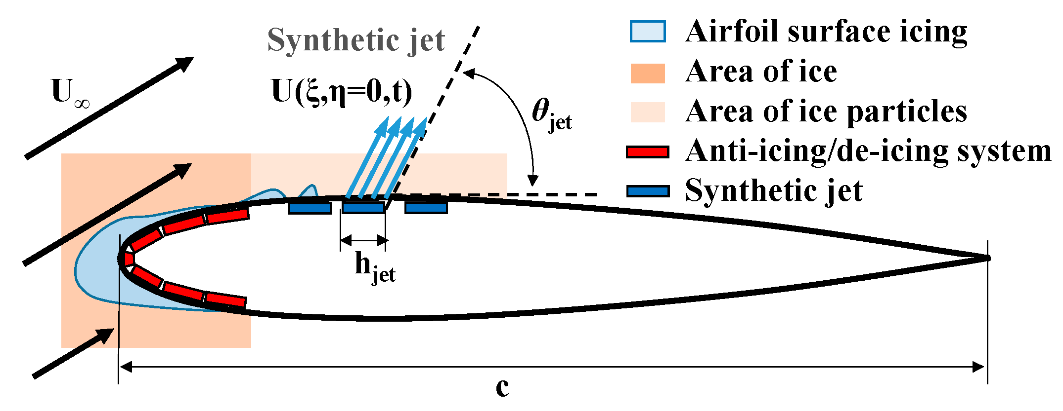
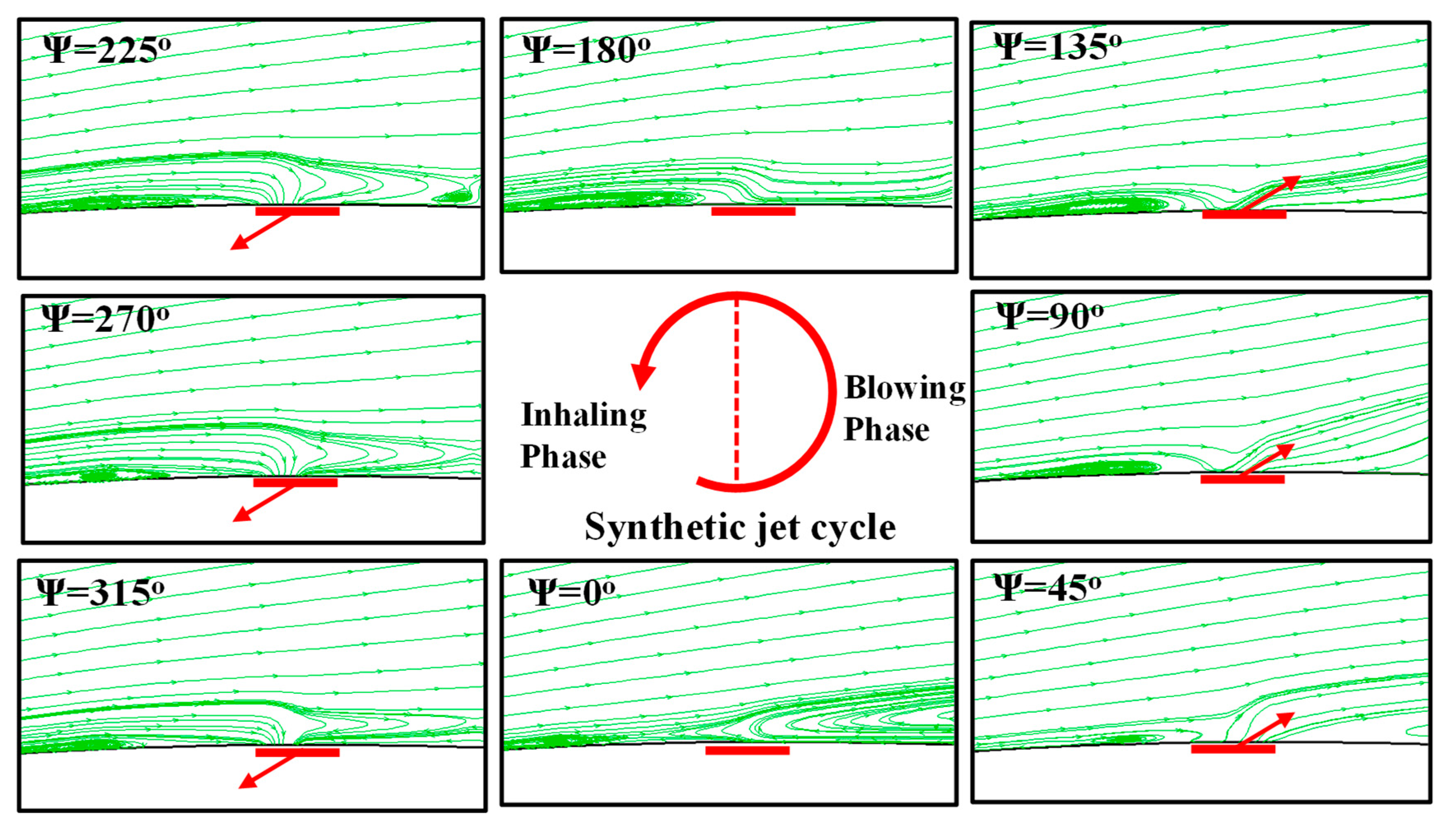
2.3. Boundary Conditions of the Synthetic Jet

The perturbation on the flow from the synthetic jet actuator on the airfoil is modeled by a suction/blowing type boundary condition [28]. The non-dimensional velocity of the synthetic jet at the actuator surface is introduced by
U ( ξ , η = 0 , t ) = c 2 h j e t U C u 0 + 2 C u m sin ( 2 π F + t ) f ( ξ ) n j e t
where ξ denotes the chordwise direction, η denotes the cross-stream direction, ζ denotes the spanwise direction, F + denotes the jet frequency, C u 0 is the steady component of the jet momentum coefficient, C u m is the unsteady component of the jet momentum coefficient, n j e t is determined by the angle of the jet with the surface, and h is the length of the jet orifice along the chordwise direction, as shown in Figure 2.
The non-dimensional jet excitation frequency is determined by
F + = ω j e t 2 π U c = ω j e t c 2 π U
The non-dimensional jet momentum coefficient is determined by
C u 0 = 2 h c ( U 0 U ) 2 , C u m = 2 h c ( U m 2 U ) 2
where U 0 and U m are respectively the amplitude of the steady, c is the speed of sound and unsteady components of velocity.
In addition, the original pressure boundary condition needs to be modified near the jet orifice. The boundary condition of pressure can be obtained by the conservation of normal momentum. Ignoring the influence of viscosity and considering the influence of the instantaneously changing normal velocity component Un, the boundary condition can be modified as:
p η = ρ U n t

3. Calculated Results and Analyses

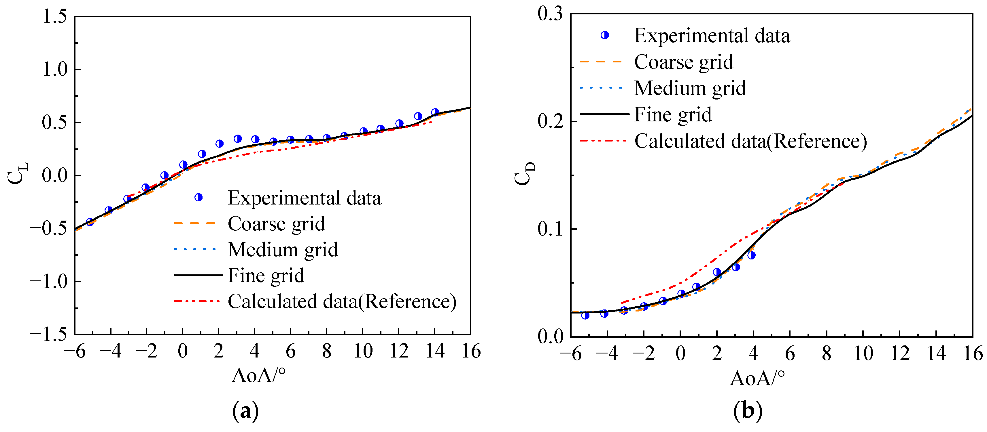
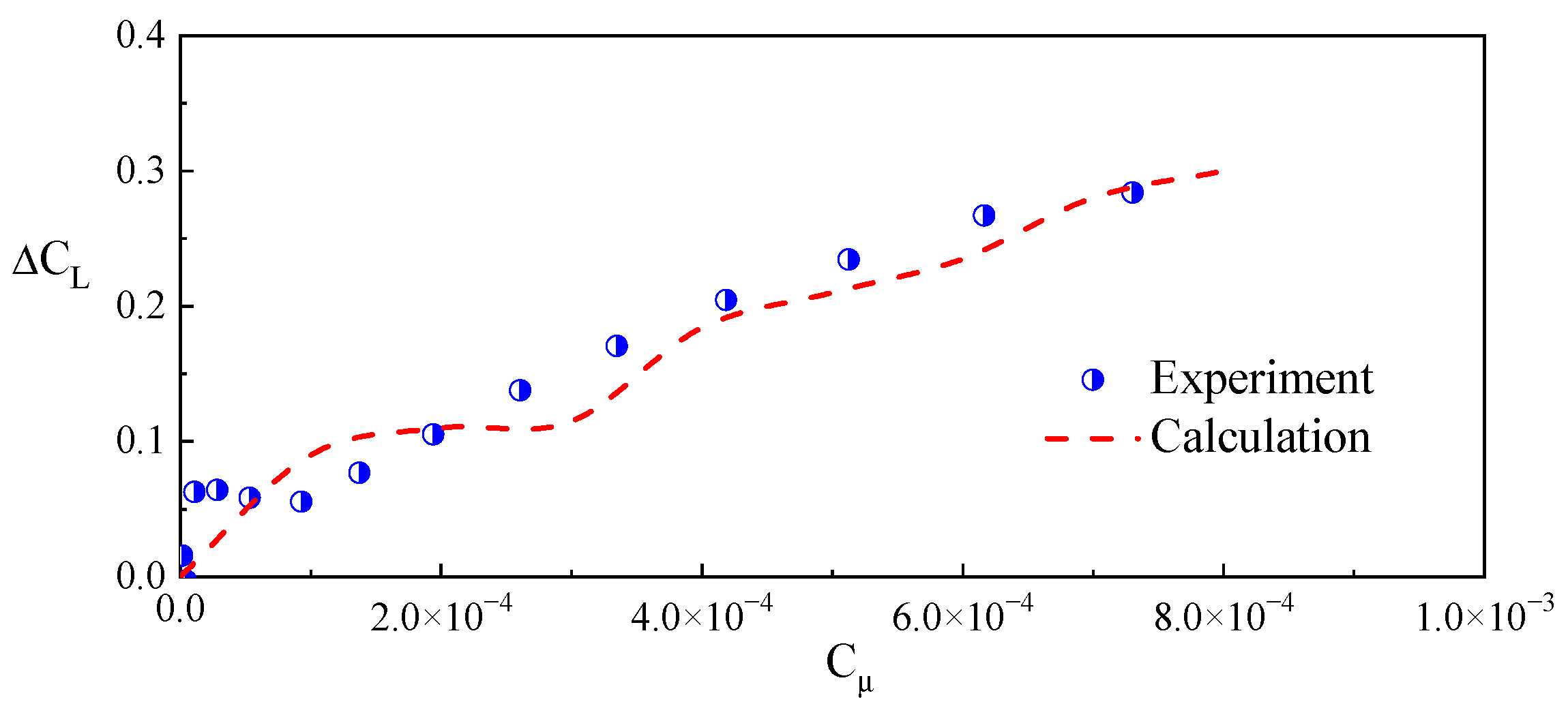
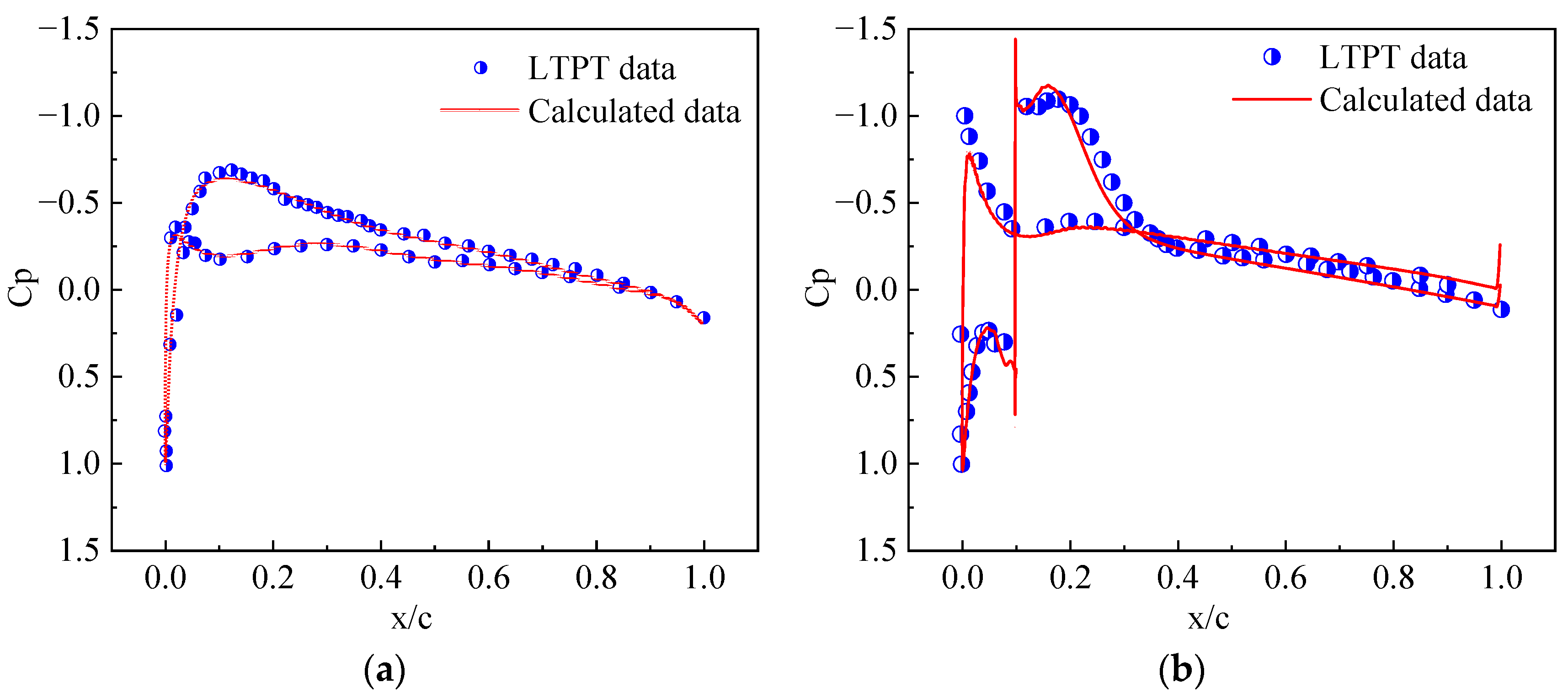
3.1. Validation of Numerical Methods

The experimental data for an iced NACA23012 airfoil, obtained at the NASA Langley Low Turbulence Pressure Tunnel (LTPT) [29] are selected to validate the accuracy of the employed numerical method. The LTPT measurements were at Mach number of 0.208 and at Reynolds number of approximately 2 × 10⁶ [30]. Figure 3 shows the modified NACA23012 airfoil and the grids used in the present study.
Figure 4 shows the aerodynamic characteristics of the modified NACA23012 airfoil obtained by using different grid resolutions. The dimensions of the grids are 279 × 69, 429 × 69, and 565 × 69, respectively. As seen, the results are all close to the experimental data, and the results simulated by the fine grid are ever so slightly closer to the test. With this in mind, the fine grid is adopted in the subsequent calculations.
Figure 5 shows pressure coefficient (Cp) distributions on the airfoil surface with the AOA of 0°. As shown, the calculated results using the fine grid are in good agreement with the LTPT data, indicating that the present CFD solver is reliable for simulating the aerodynamic characteristics of the iced airfoils.
Some experimental ice shapes on the NACA0012 airfoil at different temperatures [31] have been compared with the ones calculated by the present model. The chord is 0.5334 m, and the inflow velocity is 67.05 m/s. The median volumetric drop diameter (MVD) is 20 µm, and the liquid water content (LWC) is 1 g/m3. The icing time is 6 min. At the lowest air temperature, −28.4 °C, the typical rime ice shape takes place. The agreements between the calculated ice shapes and the measured data are very good, as shown in Figure 6a. For air temperature −4.5 °C, the calculated results agree well with the experimental shapes, as shown in Figure 6b.
A synthetic jet actuator is implemented at the leading edge of the NACA0015 airfoil with the width of 0.14% chord length. The direction of the jet is normal to the surface of the airfoil. Figure 7 shows the effect of Cum on lift coefficient increment ( Δ C l ) with F + = 1.0 . As seen, the Δ C l increases with the increase in the oscillation momentum coefficient, and the variation is close to the experimental data [32].

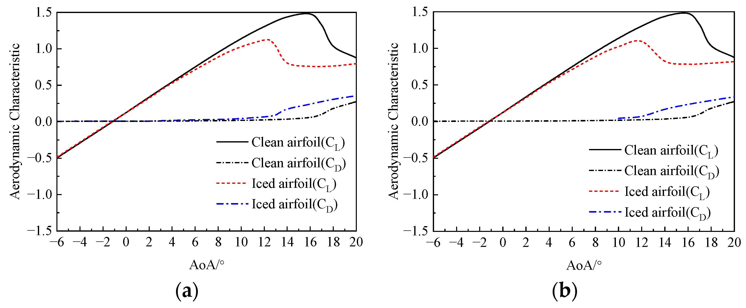
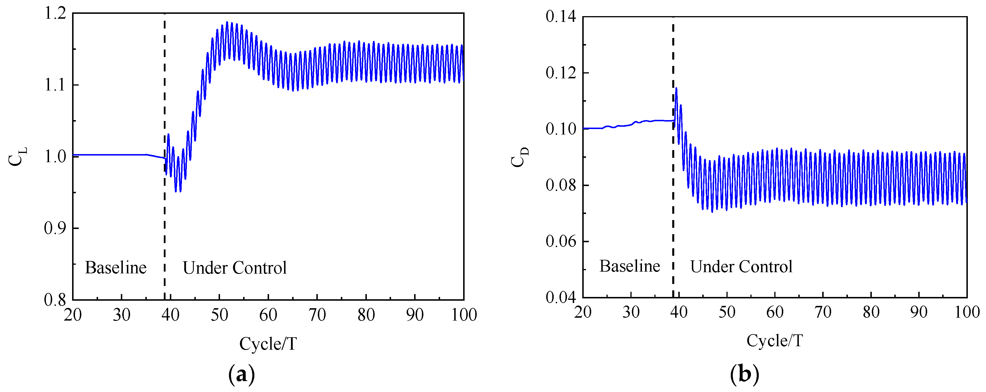
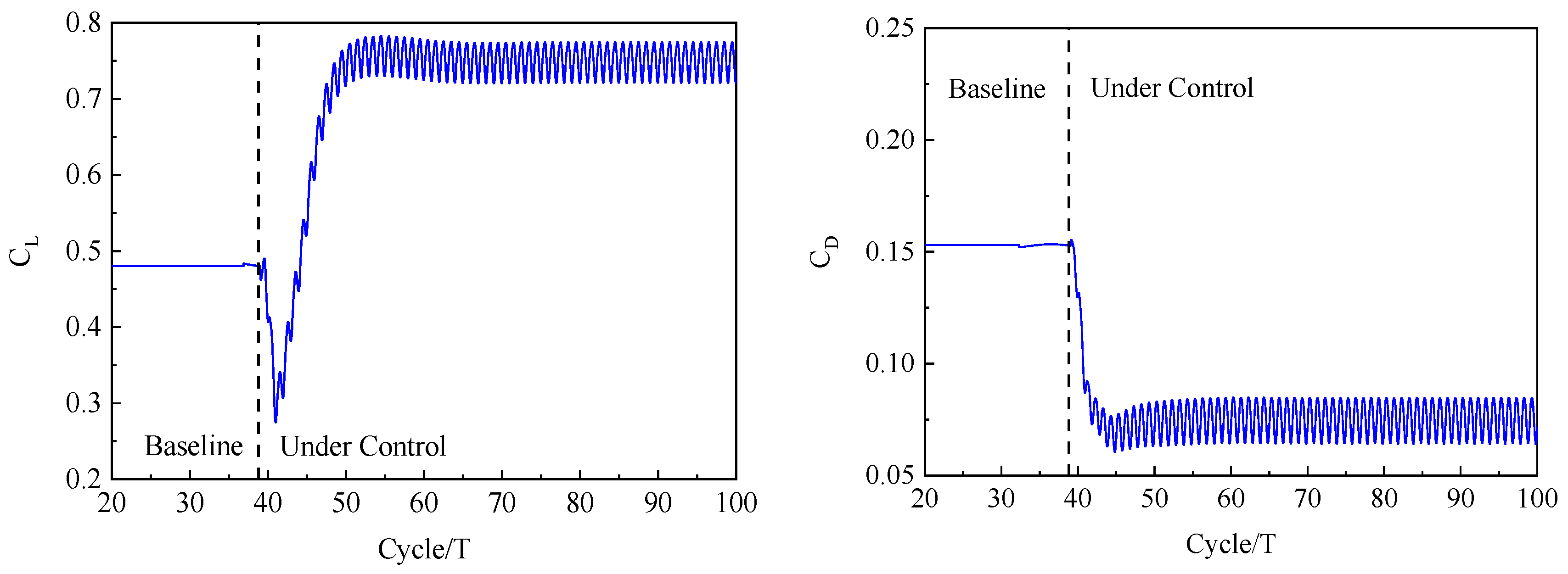
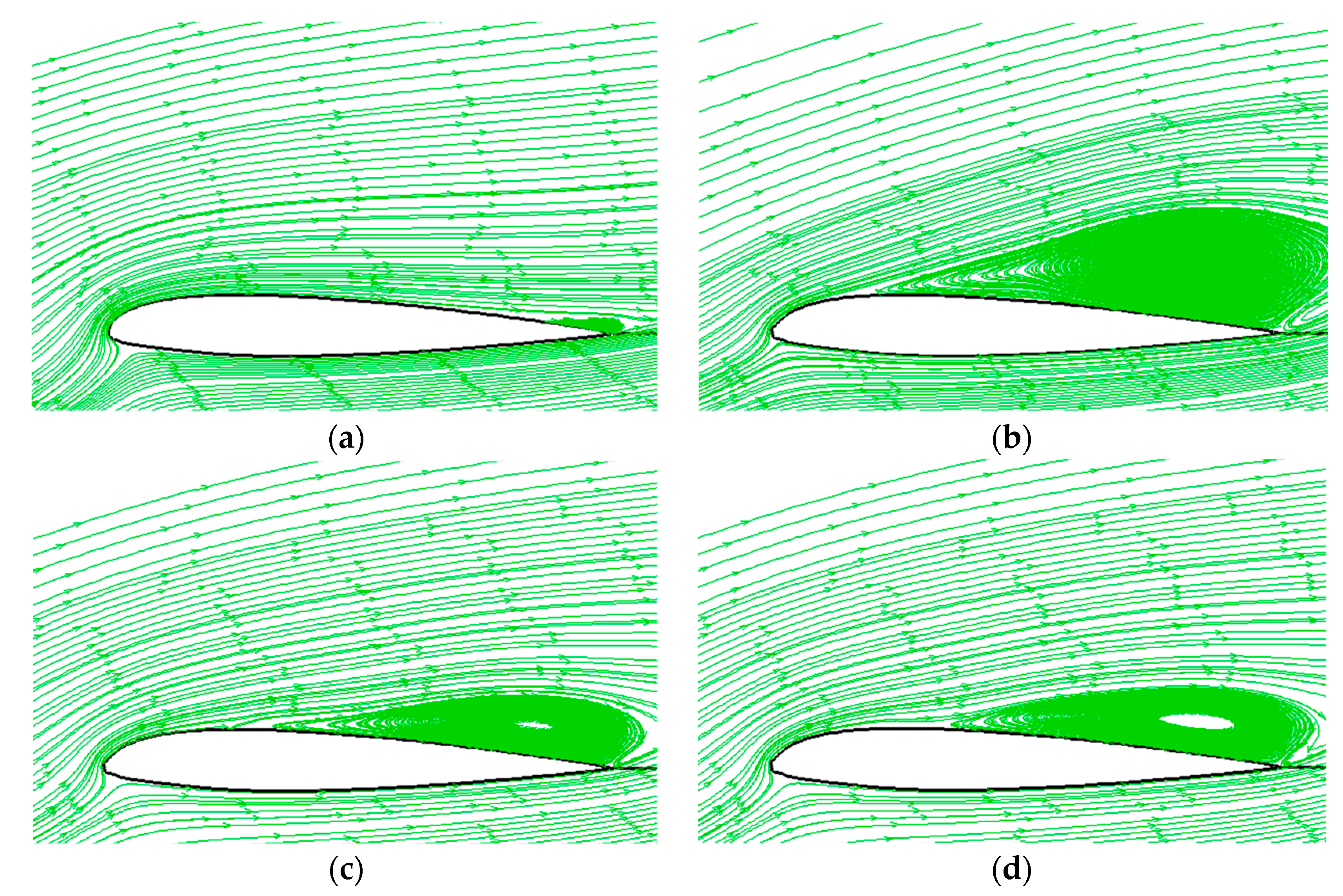
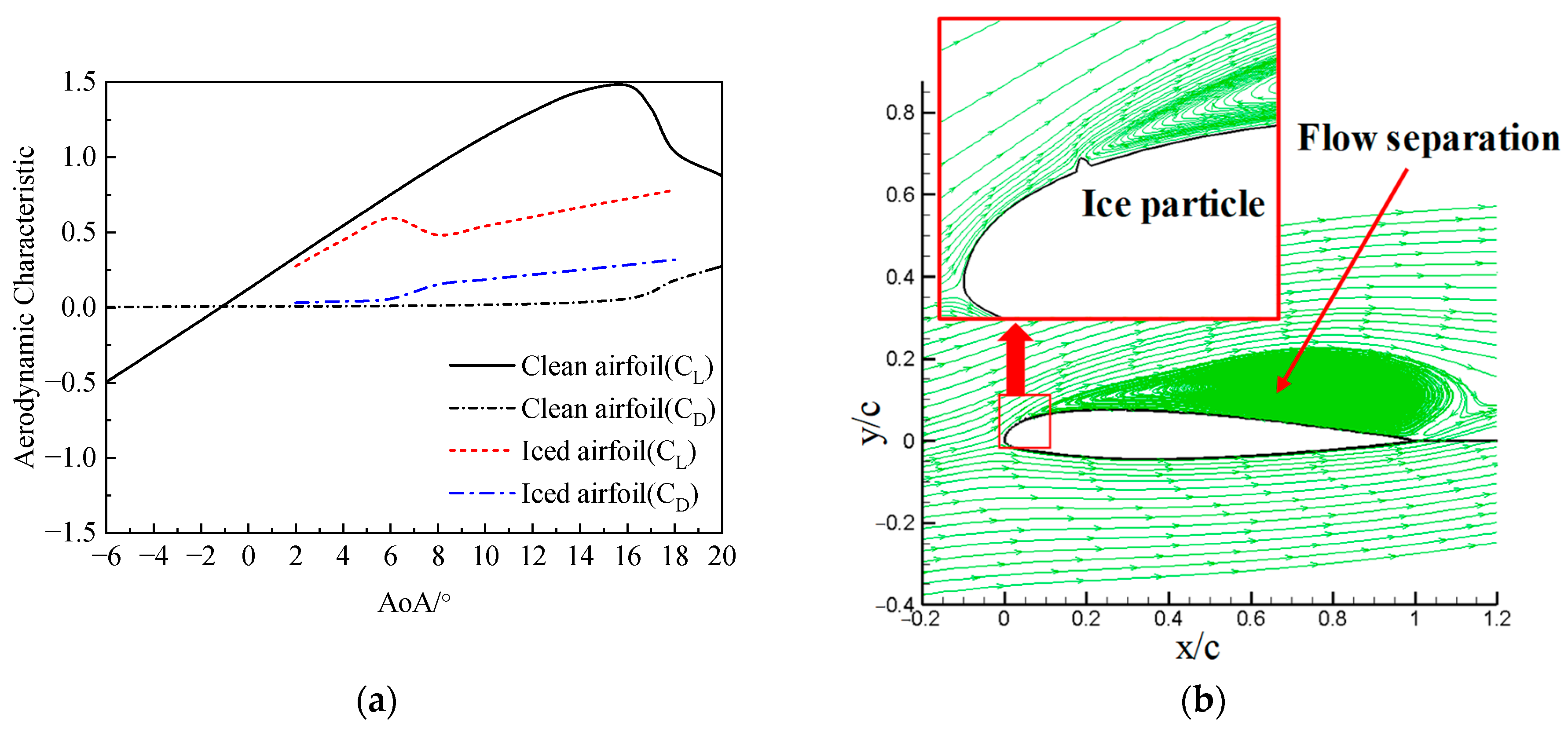
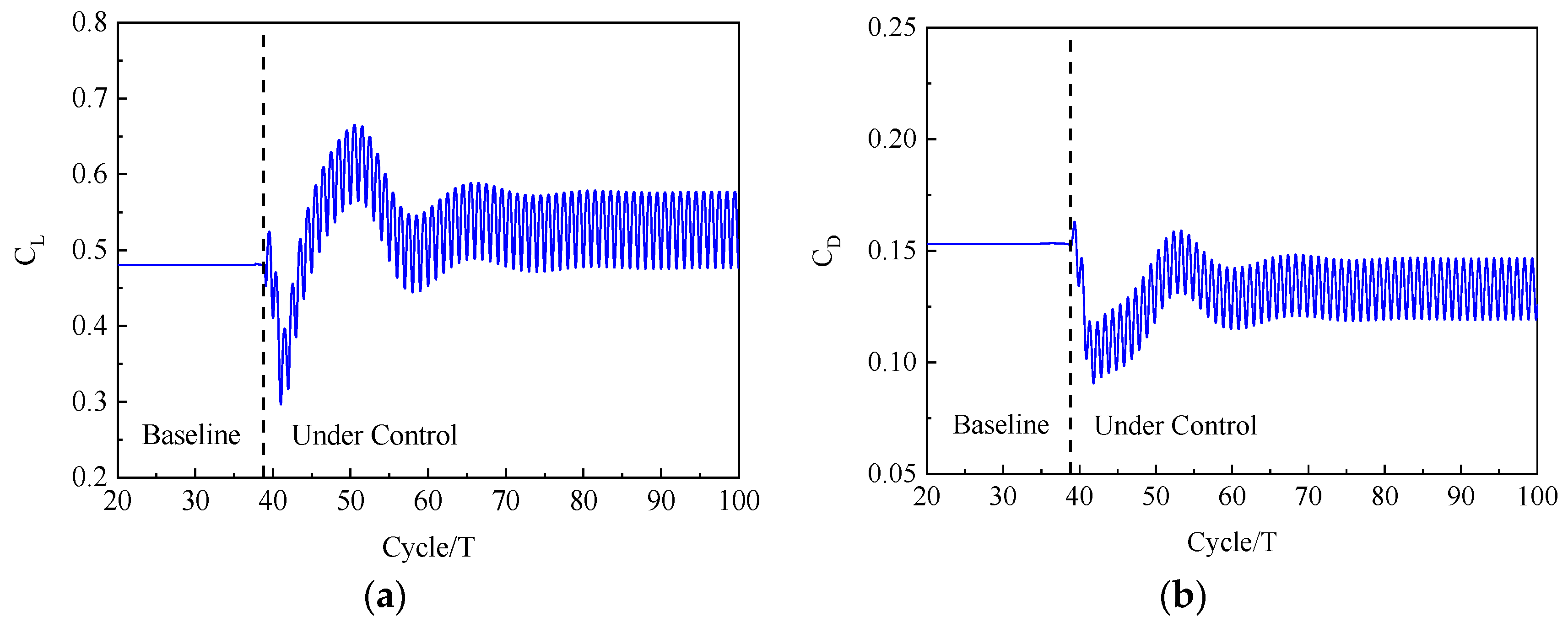
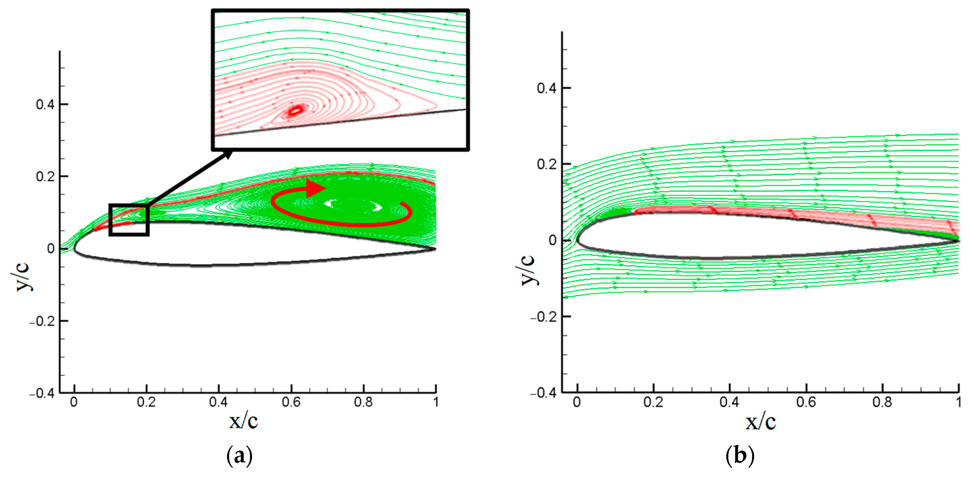
3.2. The Control Effect on the Aerodynamic Characteristics of a Typical Iced Airfoil

In the typical icing condition, the ice accretion of the NACA23012 airfoil is calculated firstly. The calculation conditions are as follows: Mach number Ma = 0.208 , a Reynolds number Re = 2 × 10 6 , liquid water content LWC = 1 × 10 - 3 , water droplet diameter MVD = 20 × 10 6 m , ambient temperature T = 15 ° C , and icing time t = 180 s .
Figure 8 shows the ice shape calculated at different AoA. As seen, the ice is near the leading edge of the airfoil at an AoA of 2° (type-A). At an AoA of 8°, the ice moves to the lower surface of the airfoil (type-B). Figure 9 shows the aerodynamic characteristics of the iced airfoil. Due to the ice shape, the stall phenomenon occurs earlier than the clean airfoil, and the drag also increases significantly.
Numerical simulation of the SJC for the aerodynamic characteristics of the NACA23012 airfoil after icing is carried out. A synthetic jet actuator is set at 25%c with a jet orifice width of 1%c. The jet control parameters are as follows: dimensionless frequency F + = 1 , momentum coefficient C u = 0 . 01 (jet orifice velocity is equal to incoming flow velocity), and jet angle θ jet = 30 ° .
Figure 10 shows the convergence process of the aerodynamic force of the type-A iced airfoil under the SJC at an AoA of 13°. It can be seen from the figure that the aerodynamic force of the iced airfoil varies with time under the SJC. Compared with the baseline state, the aerodynamic characteristics of the airfoil are significantly improved, with a 13% increase in the lift coefficient and a 19% decrease in the drag coefficient, which proves that the synthetic jet has a certain improvement effect on the aerodynamic characteristics of the iced airfoil, and temporarily alleviates the harm caused by ice accretion.
Figure 11 shows the control effects of SJAs on the aerodynamic characteristics of the iced airfoil. As seen, after the SJC, the stall angle has increased significantly and is delayed about 3°, and the iced airfoil maximum lift coefficient increases about 6%. Although the damage has not been eliminated completely, the loss of lift caused by ice accretion is still greatly alleviated.
Figure 12 shows the streamlines near the type-A iced airfoil surface under the SJC with an AoA of 13°. As seen, the flow separation region on the clean airfoil is very small, which leads to a high lift coefficient. When ice accretion occurs near the leading edge, the direction and velocity of the airflow change a lot. This leads to a considerable extent of airflow separation on the upper side of the airfoil, consequently causing significant impairment to its aerodynamic characteristics. The implementation of SJC significantly reduces the occurrence of airflow separation and effectively mitigates the adverse impact of ice accretion on the aerodynamic characteristics of the airfoil. The mechanism behind this effect is comparable to that of SJC employed to prevent stall on clean airfoils.
Figure 13 shows the streamlines near the jet orifice under the SJC. The synthetic jet angle is 30°, and an observable vortex is formed upstream of the orifice at ψ = 45 ° . During the inhaling phase, the jet vortex formed upstream will induce the mainstream to adhere to the surface of the airfoil. During the blowing phase, the energy of the jet will be injected into the boundary layer. As a result, the interaction between the jet and the mainstream results in an increase in velocity near the airfoil surface, effectively boosting the energy of the boundary layer near the airfoil surface.

3.3. The Control Effect on the Aerodynamic Characteristics of the Airfoil with a Small Ice Particle

Ice particles primarily form due to incomplete evaporation of the water film, resulting in overflow towards the rear of the heating zone after the activation of the anti/de-icing system. The utilization of SJC is proposed as a means to alleviate the adverse effects of ice particles on the aerodynamic characteristics of the airfoil. Figure 14 shows a schematic diagram of the icing shape (type-C iced airfoil) and grid with an ice particle.
Figure 15 shows the aerodynamic characteristics of a type-C iced airfoil. As seen, the damage to the aerodynamic characteristics caused by ice particles is more severe when compared to leading edge ice (type-A, type-B). The lift coefficient decreases at low AOA, and the stall occurs after an AoA of 6°. In comparison to the clean airfoil, the stall occurs approximately 10° earlier. Additionally, the figure demonstrates that the presence of ice particles alters the direction of airflow, leading to extensive airflow separation on the upper surface of the airfoil and a substantial decrease in its aerodynamic characteristics.
The SJC for the aerodynamic characteristics of the iced airfoil is numerically simulated. A synthetic jet actuator is set at 15%c with a jet orifice width of 1%c. The jet control parameters are as follows: dimensionless frequency F + = 1 , momentum coefficient of jet pulsation component C u = 0 . 01 (jet velocity is equal to incoming flow velocity), and jet angle θ jet = 30 ° . Figure 16 shows the aerodynamic characteristics of the type-C iced airfoil under the SJC at C u = 0 . 01 . As seen, the lift coefficient increases, and the drag coefficient decreases under the SJC, resulting in the improved aerodynamic characteristics of the iced airfoil.
Considering the limited enhancement of the airfoil’s aerodynamic characteristics, increasing the energy of the jet is proposed as a means to further control the iced airfoil. Assuming the other parameters remain constant, the momentum coefficient C u is adjusted to 0.015 (with the jet velocity set at 1.5 times the incoming flow velocity). Figure 17 shows the aerodynamic characteristics of the type-C iced airfoil under the SJC at C u m = 0 . 015 . As seen, it is evident that an increase in the energy of the jet leads to a gradual amplification of its impact on the mainstream flow. Consequently, this results in a significant improvement in the aerodynamic characteristics of the iced airfoil.
Figure 18 shows the streamlines around the iced airfoil surface under different momentum coefficients. At C u m = 0 . 01 , the presence of the jet weakens the separation vortex formed by icing and gradually causes it to bifurcate into two separate parts. Additionally, in local areas, a reattachment phenomenon occurs, resulting in an improvement in the aerodynamic characteristics. At C u m = 0 . 015 , the original separation vortex almost completely dissipates, with only partial separation occurring in the region between the ice particles and the jet orifice, as well as in the trailing edge area. The mainstream flow reattachment occurs in most regions on the upper surface of the airfoil, resulting in a significant enhancement of the aerodynamic characteristics. This observation emphasizes the profound influence of the jet’s momentum coefficient on the improvement of the iced airfoil’s aerodynamic performance.
Figure 19 illustrates the interaction process between the jet and the separation vortex at C u m = 0 . 01 , aiming to investigate the control mechanism of the jet on the iced airfoil when ice particles are present. During the blowing stage ( 0 ° < ψ < 180 ° ), the synthetic jet with a certain energy interferes with the separation vortex, causing the vortex to be split into two parts due to the tendency of the jet to converge with the mainstream flow. During the suction stage ( 180 ° < ψ < 360 ° ), the mainstream flow tends to approach the airfoil surface under the influence of the synthetic jet’s flow redirection, exhibiting a tendency to adhere to the airfoil surface. At this stage, if the energy of the jet is insufficient, the mainstream flow will not be able to complete the reattachment stage, and the separation vortex will reaggregate back to its initial state. In such cases, the improvement in the aerodynamic characteristics of the iced airfoil is minimal. However, when the energy of the jet is sufficiently high (e.g., C u m = 0 . 015 ), the mainstream flow will successfully reattach at this stage and disrupt the separation vortex downstream of the jet orifice. This leads to significant improvements in the aerodynamic characteristics of the iced airfoil. Nonetheless, there may still be partial separation in the region between the ice accretion and the jet orifice, as shown in Figure 18c,d.
Figure 20 shows the aerodynamic coefficients of the type-C iced airfoil under the SJC with two jet momentum coefficients. Under the SJC, the stall angle of the iced airfoil increases. It increases by about 1° at C u m = 0 . 01 , and it increases by about 3° at C u m = 0 . 015 . The iced airfoil maximum lift coefficient increases by about 12% and 26%, respectively. At the same time, the drag coefficient also decreases. Therefore, in terms of the aerodynamic characteristics of the airfoil, synthetic jet flow has a role in mitigating the hazards of icing.

3.4. Parameter Analysis of the Control Effect on the Aerodynamic Characteristics of Iced Airfoils

In order to investigate the influence of different jet flow parameters on the SJC of iced airfoils’ aerodynamic characteristics, type-A and type-C iced airfoils are chosen as research objects. Jet actuators are respectively positioned on the upper surface of the airfoils at 15%c, 20%c, 25%c, 30%c, 35%c, 40%c, 45%c, 50%c, 55%c, and 60%c from the leading edge. The width of the jet orifice is 1%c for all cases. Parameters such as excitation frequency, jet momentum coefficient, jet angle, and jet location are studied to investigate the mechanism of synthetic jets in mitigating the deterioration of iced airfoils’ aerodynamic characteristics. In the calculations, the Mach number is 0.208, and the Reynolds number is 2 × 10⁶.

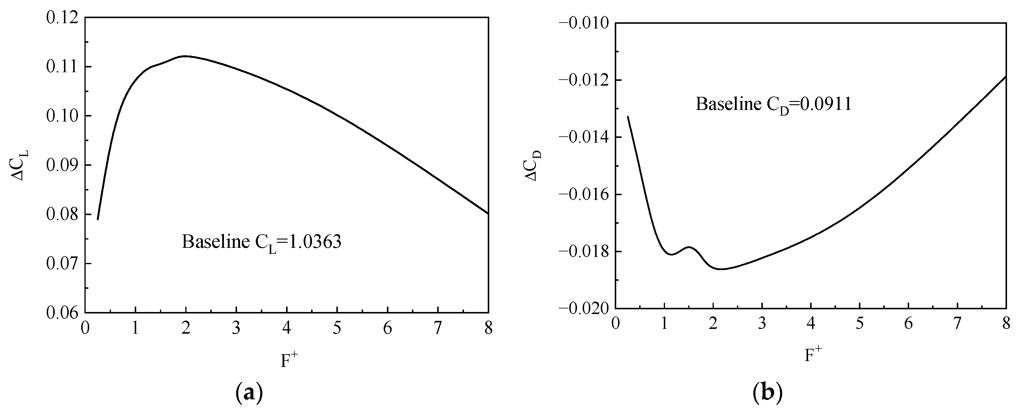
3.4.1. Effect of Jet Excitation Frequency

Firstly, the influence of the excitation frequency of the synthetic jet on the SJC of the type-A iced airfoil is studied. In this case, the jet location is set at 15%c, the jet angle is 30°, the jet momentum coefficient C u m is 0.01, and the AoA of the iced airfoil is 13°.
Figure 21 presents the variation in the aerodynamic characteristics of the iced airfoil under SJC with different excitation frequencies. It can be observed that within the range of 1 < F + < 4 , there is a significant improvement in the lift coefficient, with the best lift coefficient enhancement occurring around F + = 2 . The variation in the drag coefficient is similar. It should be noted that when F + is too high or too low, it will lead to a weakening of the effectiveness of the SJC.

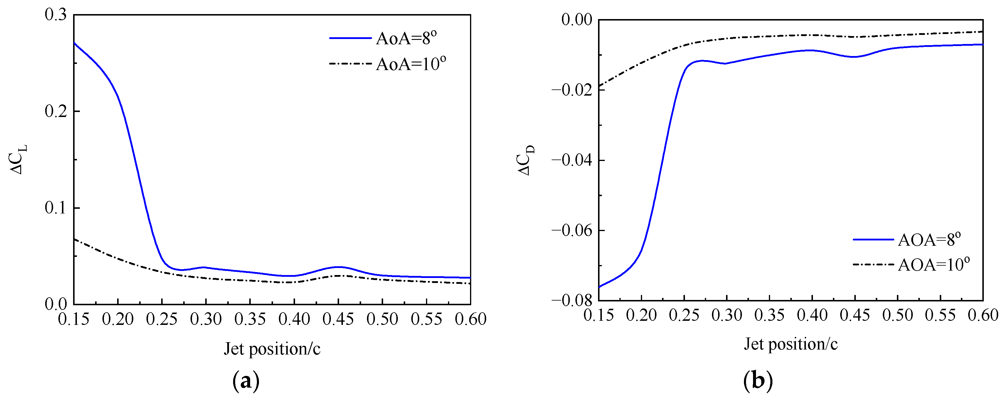
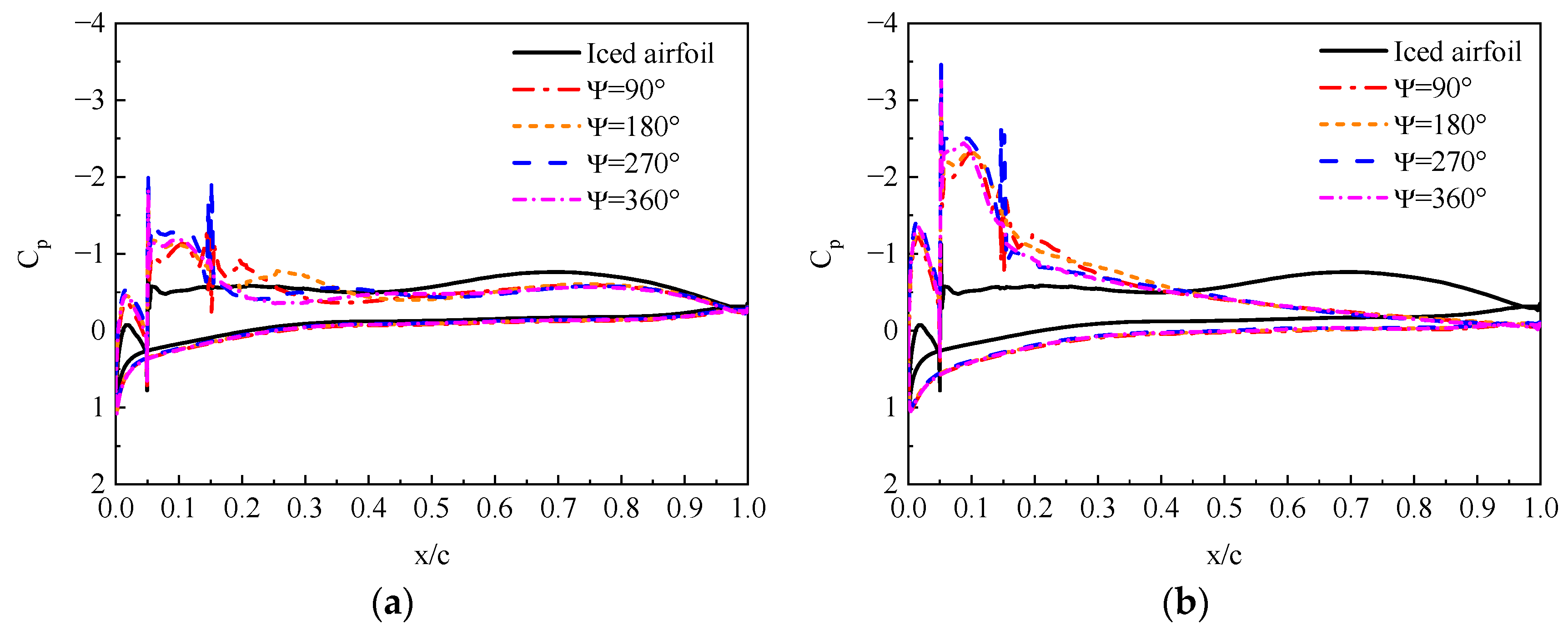
3.4.2. Effect of Jet Position

The effect of the jet location on the SJC is studied by activating each jet actuator individually on the upper surface of the iced airfoil. The jet angle is set at 30°, the jet momentum coefficient is set at 0.01, and the dimensionless frequency is set at 1.
Figure 22 compares the incremental lift and drag coefficient under SJC at different jet positions on the iced airfoil. At an AoA of 14°, the best control effect on the aerodynamic characteristics of iced airfoil is achieved when the jet is positioned in the range of 0.25 c to 0.35 c. This is because, at this AoA, flow separation begins to occur near 0.3 c on the upper surface of the airfoil due to icing. The closer the synthetic jet is to the separation point, the better the control effect on the flow separation. When the jet position is further away from the separation point, the control effect is weakened to varying degrees.
Unlike the flow condition around the type-A iced airfoil, for the type-C iced airfoil, due to the obstruction of the ice particle, flow separation almost covers the entire upper surface of the airfoil. Therefore, all jets are located within the separated flow region.
In view of this, the discussion focuses on the jet positions within the separated flow region by activating each jet actuator on the upper surface of the type-C iced airfoil. The jet angle is set at 30°, the jet momentum coefficient is set at 0.015, the dimensionless frequency is set at 1, and the airfoil has an AoA of 8° and 10°. Figure 23 illustrates the relationship between the change in the lift and drag coefficient of the type-C iced airfoil and the jet position. As seen, when the jet position is closer to the ice formation, there is a greater improvement in the aerodynamic characteristics of the airfoil. This is because as the separated vortex moves downstream of the ice particle, its energy gradually intensifies. Therefore, to effectively control the flow separation, the synthetic jet needs to provide higher energy input to counteract the strengthening vortex and promote reattachment of the separated flow.

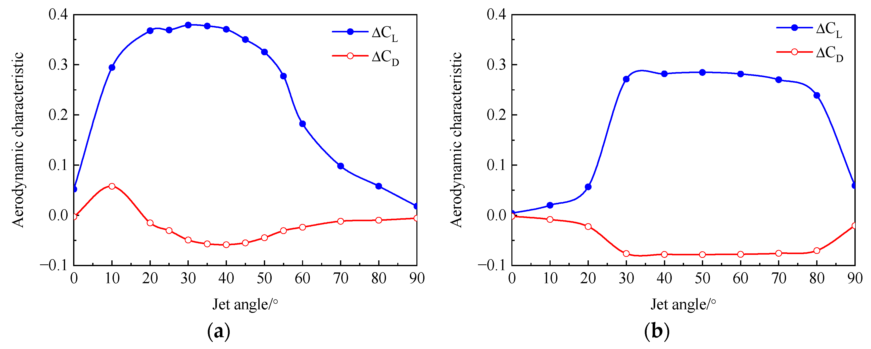
3.4.3. Effect of Jet Angle

The effectiveness of SJC on the iced airfoil is studied by setting a series of jet angles. For the type-A iced airfoil, the jet position is set at 25%c, the jet momentum coefficient is set at 0.01, the dimensionless frequency is set at 1, and the AoA of the airfoil is set at 14°. For the type-C iced airfoil, the jet position is set at 15%c, the jet momentum coefficient is set at 0.015, the dimensionless frequency is set at 1, and the AoA of the airfoil is set at 8°.
Figure 24 illustrates the effect of the jet angle on the aerodynamic characteristics of the iced airfoil. It can be seen that when the jet angle is too small or too large, the control effect on the aerodynamic characteristics of the airfoil is poor. This is primarily due to the fact that the synthetic jet influences the flowfield of the iced airfoil through the combined effect of its own normal and tangential velocities.
For the type-A iced airfoil, since the jet orifice is located in front of the separated vortex, a larger tangential velocity, after being influenced by the normal velocity, is more conducive to transporting energy, making the mainstream easier to reattach, as shown in Figure 25. For the type-C iced airfoil, as the jet orifice is located within the separation region, sufficient normal velocity is required to interact with the mainstream outside the separation region. If there is insufficient normal energy, relying solely on tangential energy cannot affect the airflow motion within the separation region or suppress the phenomenon of flow separation. As shown in Figure 26, at a jet angle of 10°, the jet motion is influenced by the counterclockwise movement of the separated vortex during the blowing phase, and the jet moves with the separated vortex, unable to achieve suppression. At a jet angle of 60°, with a significant normal velocity and a small adverse pressure gradient, the separated vortex is divided, and the jet interacts with the mainstream, guiding the mainstream to reattach to the airfoil (the red line in the figure). In conclusion, for ice near the leading edge, the optimal range for the jet angle is between 20° and 50°. Conversely, for ice with notable protrusions on the upper surface, a preferred range of 30° to 80° for the jet angle is recommended.

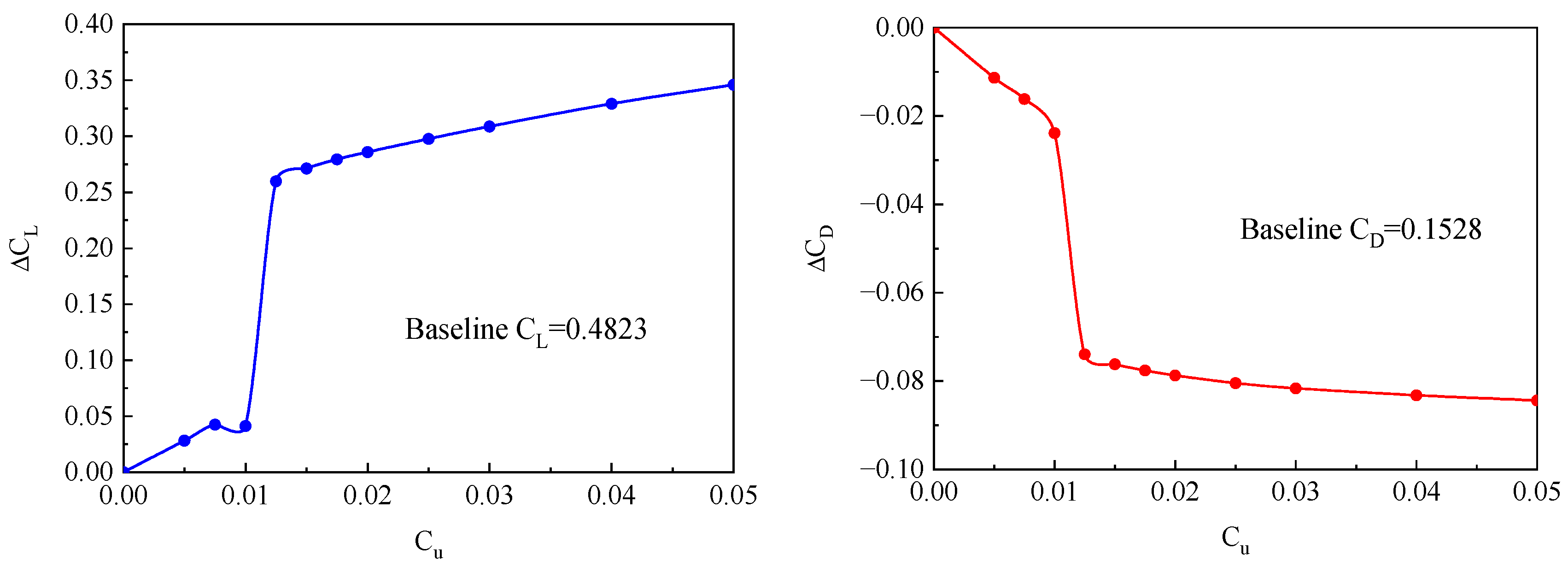
3.4.4. Effect of Momentum Coefficient

The influence of the jet momentum coefficient has already been preliminarily discussed in the preceding section. This section further conducts a numerical analysis of the SJC with different jet momentum coefficients on the aerodynamic characteristics of a type-C iced airfoil. Among them, the jet position is at 15%c, the jet angle is 30°, the non-dimensional frequency is 1, the AoA of the iced airfoil is 8°, and the range of the momentum coefficient is 0.005 < C u m < 0 . 05 .
Figure 27 shows the variation in the aerodynamic characteristics of the iced airfoil with respect to the momentum coefficient. As the jet momentum coefficient increases, the synthetic jet has a better control effect on the aerodynamic characteristics of the iced airfoil. Within the range of momentum coefficients from 0.01 to 0.0125, there is a sudden increase in the variation in the aerodynamic characteristics. This is mainly because, before reaching a jet momentum coefficient of 0.0125 (where the jet velocity is 1.25 times the incoming flow velocity), the jet does not have enough kinetic energy to change the state of the separation vortex or guide the mainstream to reattach to the upper surface of the airfoil, as shown in Figure 19. After further increasing the jet momentum coefficient, there is no significant enhancement in the aerodynamic characteristics of the iced airfoil.
Figure 28 presents the variation in the pressure coefficient on the iced airfoil under different jet momentum coefficients. When the momentum coefficient is relatively low, the pressure coefficient on the upper surface of the airfoil undergoes small fluctuations due to the influence of the synthetic jet, occurring only in the region near the jet orifice. As the jet momentum coefficient reaches a level where it can control the separation phenomenon, the pressure coefficients on both the upper and lower surfaces of the iced airfoil undergo significant changes. Their distribution becomes closer to that of a clean airfoil.

4. Conclusions

A set of numerical analysis methods is developed to investigate the control effect on the aerodynamic characteristics of the iced airfoil using the synthetic jet. The SJC effects on the aerodynamic characteristics of airfoils with different ice shapes are systematically analyzed for the first time, and several valuable conclusions are derived.
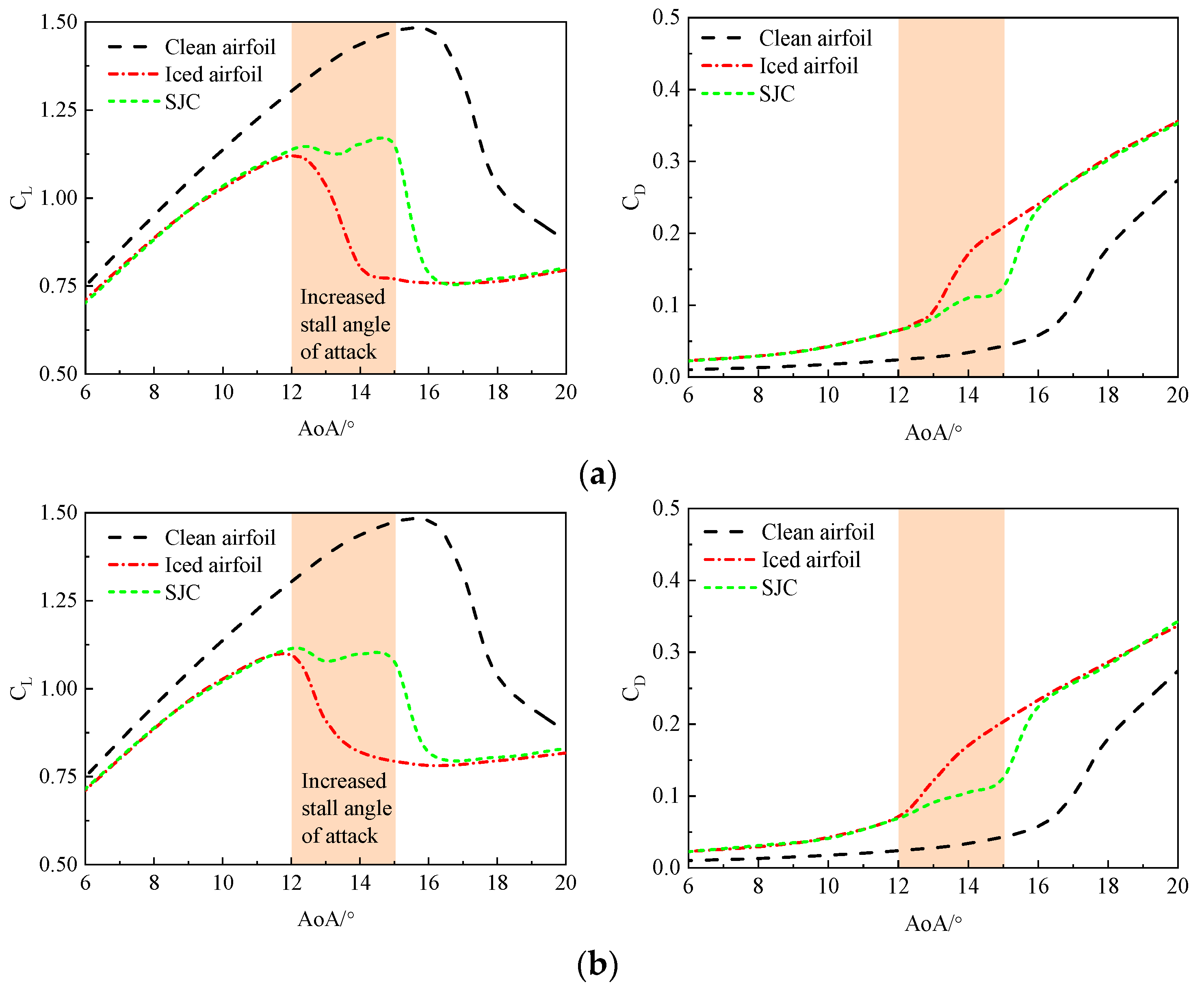
  • Through the numerical simulation of iced airfoil control based on the synthetic jet, the synthetic jet can effectively improve the airfoil lift force, reduce the airfoil drag force, delay a certain stall angle of attack, and significantly improve the aerodynamic characteristics of the iced airfoil.
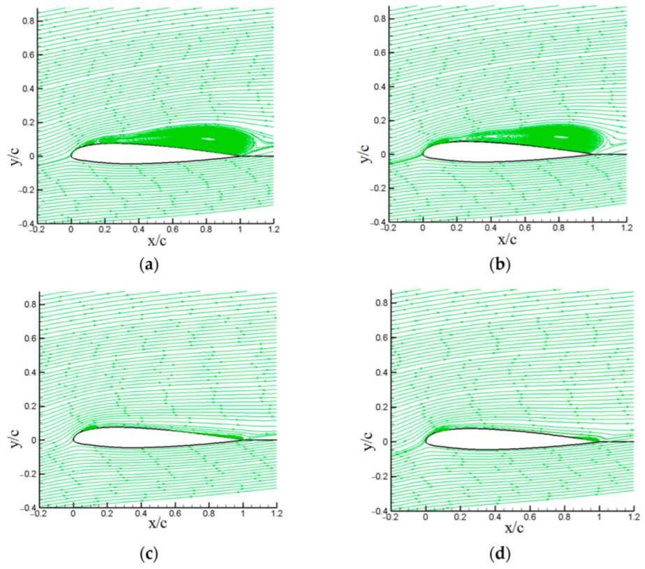
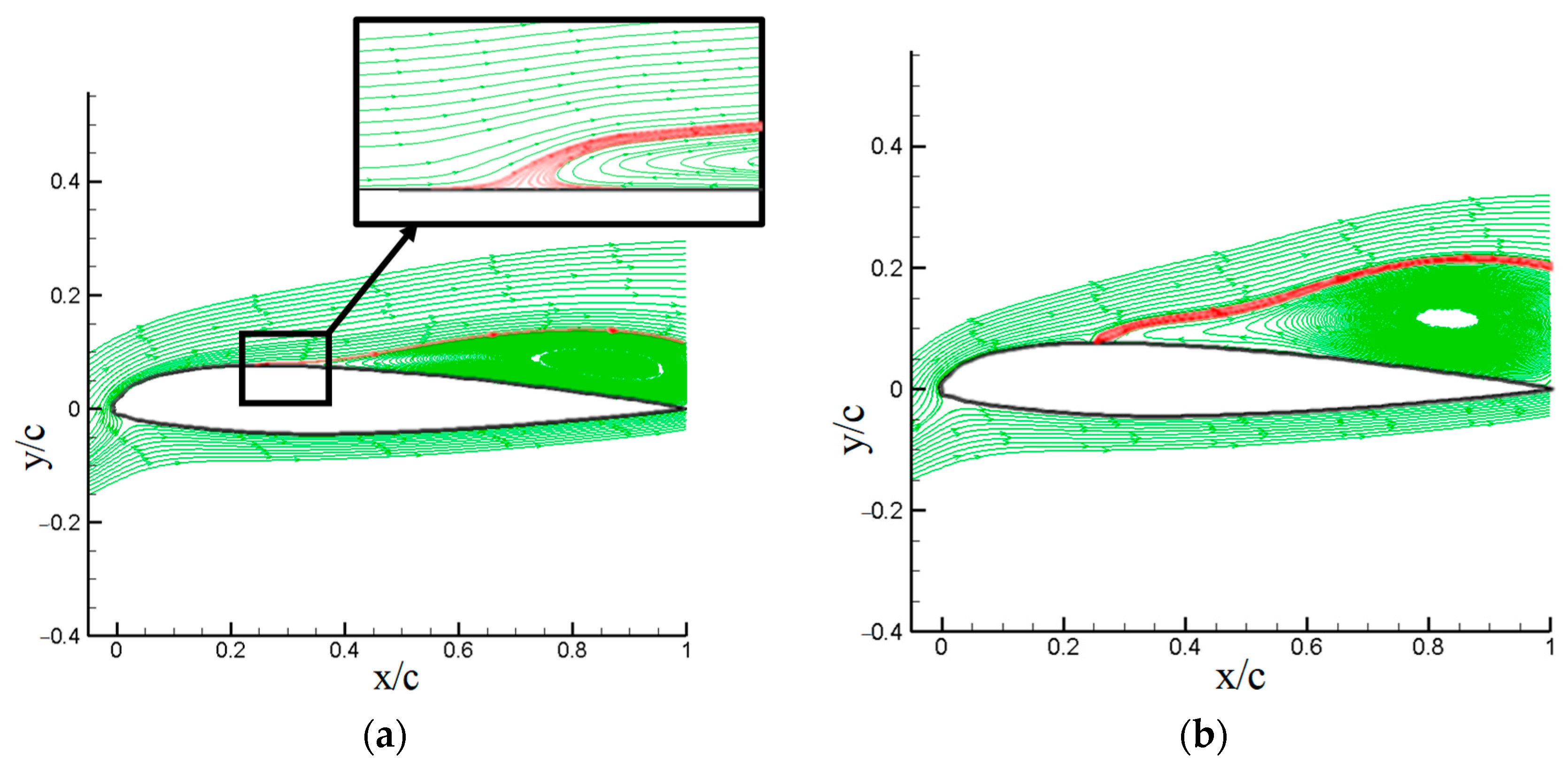
  • In the case of the leading edge iced airfoil, the synthetic jet can reduce the separation area on the upper surface, effectively controlling flow separation. The mechanism behind this phenomenon is similar to that of the synthetic jet controlling stall in the clean airfoil. In this case, the iced airfoil maximum lift coefficient increases by about 6% under the SJC.
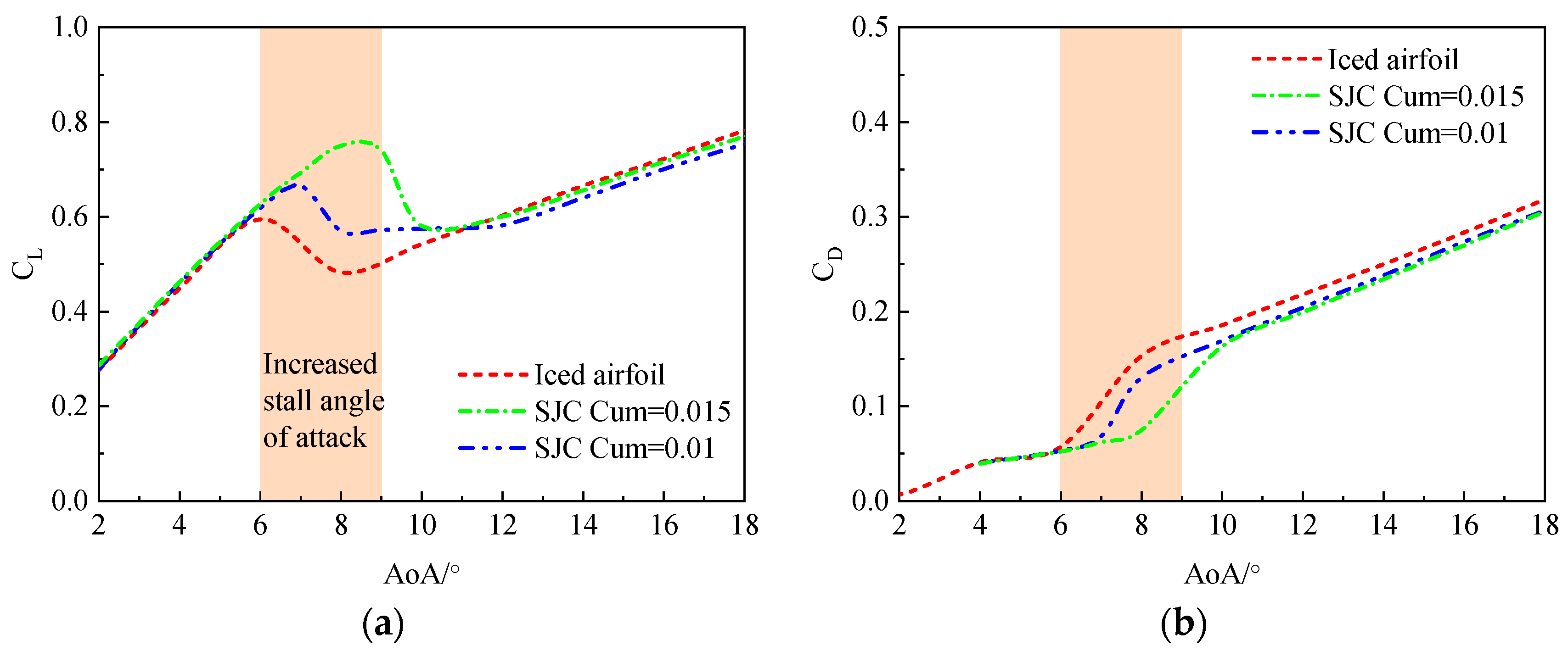
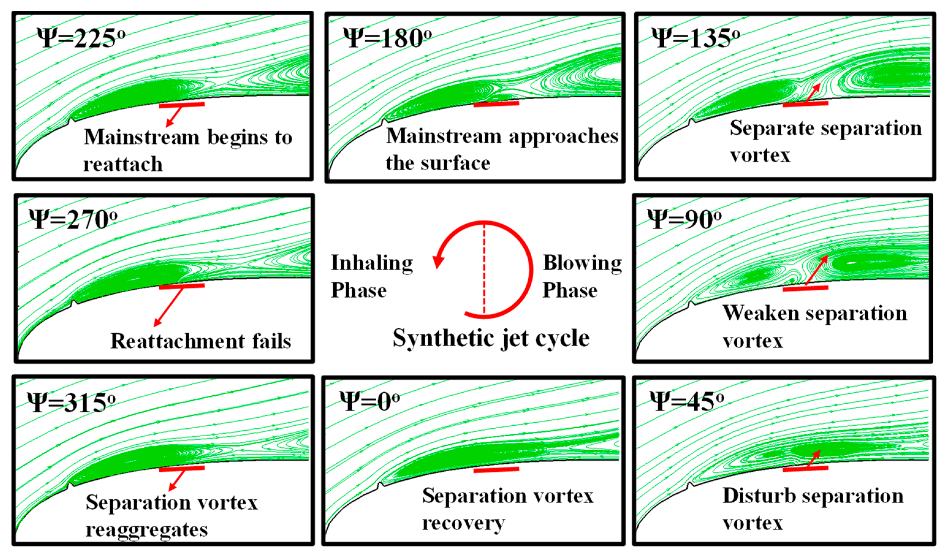
  • In the case of the airfoil with a small ice particle on the upper surface, there is a tendency for the mainstream to reattach under the SJC. When the energy of the jet is sufficient, it interacts with the mainstream, reducing the separation vortex downstream of the jet orifice and greatly improving the aerodynamic characteristics of the iced airfoil. However, partial separation phenomena still exist in the region between the ice particle and the synthetic jet orifice. In this case, the iced airfoil maximum lift coefficient increases by about 26% under the SJC.
  • In terms of selecting the control parameters, the optimal range for the jet angle is between 20° and 50° for ice near the leading edge. The optimal range for the jet angle is between 30° to 80° for ice with notable protrusions on the upper surface. Within the range of 1 < F + < 4 , there is a significant improvement in the lift coefficient, with the best lift coefficient enhancement occurring around F + = 2 . The variation in the drag coefficient is similar.

Author Contributions

Conceptualization, X.C. and G.Z.; Data curation, W.B.; Formal analysis, X.C.; Funding acquisition, Q.Z. and G.Z.; Investigation, X.C., W.B. and G.Z.; Methodology, W.B. and G.Z.; Project administration, Q.Z.; Resources, Q.Z.; Supervision, Q.Z.; Validation, X.C. and W.B.; Visualization, W.B.; Writing—original draft, X.C. and W.B.; Writing—review and editing, X.C. and W.B. All authors have read and agreed to the published version of the manuscript.

Funding

This study was co-supported by the National Natural Science Foundation of China (No. 12072156) and the Priority Academic Program Development of Jiangsu Higher Education Institutions.

Data Availability Statement

The data that support the findings of this study are available from the corresponding author upon reasonable request.

Conflicts of Interest

The authors declare no conflict of interest. The funders had no role in the design of the study; in the collection, analyses, or interpretation of data; in the writing of the manuscript; or in the decision to publish the results.

References

  1. Lynch, F.T.; Khodadoust, A. Effects of Ice Accretions on Aircraft Aerodynamics. Prog. Aeronaut. Sci. 2001, 37, 669–767. [Google Scholar] [CrossRef]
  2. Flemming, R.; David, A. High Speed Ice Accretion on Rotorcraft Airfoils. In Proceedings of the 39th Annual Forum of the American Helicopter Society, St. Louis, MO, USA, 9–11 May 1983. [Google Scholar]
  3. Morelli, M.; Guardone, A. A simulation framework for rotorcraft ice accretion and shedding. Aerosp. Sci. Technol. 2022, 129, 107157. [Google Scholar] [CrossRef]
  4. Liu, X.; Chen, H. Slippery Liquid-infused Porous Electric Heating Coating for Anti-icing and De-icing Applications. Surf. Coat. Technol. 2019, 374, 889–896. [Google Scholar] [CrossRef]
  5. Li, L.; Liu, Y. An Experimental Study on a Hot-air-based Anti-/de-icing System for Aero-engine Inlet Guide Vanes. Appl. Therm. Eng. 2020, 167, 114778. [Google Scholar] [CrossRef]
  6. Zhu, Y.; Palacios, L. Numerical simulation and experimental validation of tailored wave guides for ultrasonic de-icing on aluminum plates. In Proceedings of the 51st AIAA/ASME/ASCE/AHS/ASC Structures, Structural Dynamics and Materials Conference, Orlando, FL, USA, 12–15 April 2010. [Google Scholar]
  7. Esmaeilifar, E.; Raj, L. Computational simulation of aircraft electrothermal de-icing using an unsteady formulation of phase change and runback water in a unified framework. Aerosp. Sci. Technol. 2022, 130, 107936. [Google Scholar] [CrossRef]
  8. Liipfert, E.; Pottler, K. Parabolic Trough Optical Performance Analysis Techniques. J. Sol. Energy Eng. 2007, 147, 147–152. [Google Scholar] [CrossRef]
  9. Pouryoussefi, G.; Mirzaei, M. Experimental investigation of separation bubble control on an iced airfoil using plasma actuator. Appl. Therm. Eng. 2016, 100, 1334–1341. [Google Scholar] [CrossRef]
  10. Smith, B.; Glezer, A. Jet vectoring using synthetic jets. J. Fluid Mech. 2002, 458, 1–34. [Google Scholar] [CrossRef]
  11. Smith, B.; Glezer, A. The Formation and Evolution of Synthetic Jets. Phys. Fluids. 1998, 10, 2281–2297. [Google Scholar] [CrossRef]
  12. Nishibe, K.; Fujita, Y. Experimental and Numerical Study on the Flow Characteristics of Synthetic Jets. J. Fluid Sci. Technol. 2011, 6, 426–436. [Google Scholar] [CrossRef]
  13. Seifert, A.; Darabi, A. Delay of Airfoil Stall by Periodic Excitation. AIAA J. 1999, 33, 691–707. [Google Scholar] [CrossRef]
  14. Gilarranz, J.; Traub, L. A New Class of Synthetic Jet Actuators, Part II: Application to flow separation control. J. Fluids Eng. 2005, 127, 377–387. [Google Scholar] [CrossRef]
  15. Lee, B.; Kim, M. Separation Control Characteristics of Synthetic Jets with Circular Exit Array. In Proceedings of the 6th AIAA Flow Conference, New Orleans, LA, USA, 25–28 June 2012. [Google Scholar]
  16. He, M.; Zhang, L. Flow Characteristics and Parameter Influence of the Under-Expansion Jet on Circulation Control Airfoil. Energies 2023, 16, 3818. [Google Scholar] [CrossRef]
  17. Singh, D.; Jain, A. Active Flow Control over a NACA23012 Airfoil using Hybrid Jet. Def. Sci. J. 2021, 71, 721–729. [Google Scholar] [CrossRef]
  18. Ma, C.; Xu, H. Parameter-Based Design and Analysis of Wind Turbine Airfoils with Conformal Slot Co-Flow Jet. J. Appl. Fluid Mech. 2023, 16, 269–283. [Google Scholar] [CrossRef]
  19. Durrani, D.; Haider, B. Study of Stall Delay over a Generic Airfoil using Synthetic Jet Actuator. In Proceedings of the 49th AIAA Aerospace Sciences Meeting including the New Horizons Forum and Aerospace Exposition, Orlando, FL, USA, 4–7 January 2011. [Google Scholar]
  20. Jin, Z.; Wang, Y. An Experimental Investigation into the Effect of Synthetic Jet on the Icing Process of a Water Droplet on a Cold Surface. Int. J. Heat Mass Transf. 2014, 72, 553–558. [Google Scholar] [CrossRef]
  21. Nagappan, N.; Golubev, V. Parametric Analysis of Icing Control Using Synthetic Jet Actuators. In Proceedings of the 21st AIAA Computational Fluid Dynamics Conference, San Diego, CA, USA, 24–27 June 2013; p. 2453. [Google Scholar]
  22. Nagappan, N.; Golubev, V. On Icing Control Using Thermally Activated Synthetic Jets. In Proceedings of the 51st AIAA Aerospace Sciences Meeting Including the New Horizons Forum and Aerospace Exposition, Grapevine, TX, USA, 7–10 January 2013; pp. 109–126. [Google Scholar]
  23. Chen, X.; Zhao, Q. Numerical analysis of aerodynamic characteristics of iced rotor in forward flight. AIAA J. 2019, 57, 1523–1537. [Google Scholar] [CrossRef]
  24. Chen, X.; Ding, Y. Experimental Investigations on Flow Control of the Rotor via the Synthetic Jets in Forward Flight. Aerospace 2023, 10, 628. [Google Scholar] [CrossRef]
  25. Fu, L. A low-dissipation finite-volume method based on a new TENO shock-capturing scheme. Comput. Phys. Commun. 2019, 235, 25–39. [Google Scholar] [CrossRef]
  26. Bian, W.; Zhao, G. High-fidelity simulation of blade vortex interaction of helicopter rotor based upon TENO scheme. Chin. J. Aeronaut. 2023, 36, 275–292. [Google Scholar] [CrossRef]
  27. Messinger, B. Equilibrium Temperature of an Unheated Icing Surface as a Function of Air Speed. J. Aeronaut. Sci. 1953, 20, 29–42. [Google Scholar] [CrossRef]
  28. Zhao, Q.; Chen, X. Investigations of synthetic jet control effects on helicopter rotor in forward flight based on CFD method. Aeronaut. J. 2018, 122, 1102–1122. [Google Scholar] [CrossRef]
  29. Bragg, M.; Broeren, A. Iced-airfoil aerodynamics. Prog. Aeronaut. Sci. 2005, 41, 323–362. [Google Scholar] [CrossRef]
  30. Marques, S.; Badcock, K. Validation study for prediction of iced aerofoil aerodynamics. Aeronaut. J. 2016, 114, 103–111. [Google Scholar] [CrossRef]
  31. Mingione, G.; Brandi, V. Ice Accretion Prediction on Multielement Airfoils. J. Aircr. 1998, 35, 240–246. [Google Scholar] [CrossRef]
  32. Hassan, A.; Straub, F. Effects of surface blowing/suction on the aerodynamics of helicopter rotor blade-vortex interactions (BVI)—A numerical simulation. In Proceedings of the 52nd Annual Forum of AHS, Washington, DC, USA, 4–6 June 1996. [Google Scholar]
Figure 1. The analytical procedure of the SJC on the airfoil in icing conditions.
Energies 16 07487 g001
Figure 2. Jet boundary conditions on an iced airfoil.
Energies 16 07487 g002
Figure 3. The modified NACA23012 airfoil and the grids around the airfoil.
Energies 16 07487 g003
Figure 4. Aerodynamic characteristics of the modified NACA23012 airfoil. (a) CL; (b) CD.
Energies 16 07487 g004
Figure 5. Pressure coefficient distributions of the NACA23012 airfoil. (a) clean airfoil; (b) iced airfoil.
Energies 16 07487 g005
Figure 6. Ice shapes on a NACA0012 airfoil at different temperatures. (a) T = −28.4 °C; (b) T = −4.5 °C.
Energies 16 07487 g006
Figure 7. Effect of Cum on lift coefficient increment.
Energies 16 07487 g007
Figure 8. Schematic diagram of icing shape and grid. (a) AoA = 2 ° (type-A); (b) AoA = 8 ° (type-B).
Energies 16 07487 g008
Figure 9. The change in aerodynamic characteristics before and after icing. (a) Type-A; (b) Type-B.
Energies 16 07487 g009
Figure 10. The aerodynamic characteristic of the iced airfoil under the SJC. (a) CL; (b) CD.
Energies 16 07487 g010
Figure 11. The control effects of SJAs on the aerodynamic characteristics of the iced airfoil. (a) Type-A; (b) Type-B.
Energies 16 07487 g011
Figure 12. The streamlines near the type-A iced airfoil surface under the SJC with an AoA of 13°. (a) clean airfoil; (b) iced airfoil; (c) SJC at ψ = 90 ° (blowing); (d) SJC at ψ = 270 ° (inhaling).
Energies 16 07487 g012
Figure 13. The streamlines near the jet orifice under the SJC. (red arrows: direction of jet).
Energies 16 07487 g013
Figure 14. Ice shape with ice particle and the airfoil grid.
Energies 16 07487 g014
Figure 15. Aerodynamic characteristics of the iced airfoil before and after icing. (a) Aerodynamic characteristics; (b) The streamlines of the iced airfoil.
Energies 16 07487 g015
Figure 16. The aerodynamic characteristics of the type-C iced airfoil under the SJC. (a) CL; (b) CD.
Energies 16 07487 g016
Figure 17. The aerodynamic characteristics of the type-C iced airfoil under the SJC at C u m = 0 . 015 .
Energies 16 07487 g017
Figure 18. The streamlines around the iced airfoil surface under different momentum coefficients. (a) C u m = 0 . 01 , ψ = 90 ° (blowing); (b) C u m = 0 . 01 , ψ = 270 ° (inhaling); (c) C u m = 0 . 015 , ψ = 90 ° (blowing); (d) C u m = 0 . 015 , ψ = 270 ° (inhaling).
Energies 16 07487 g018
Figure 19. The interaction process between the jet and the separation vortex at C u m = 0 . 01 . (red arrows: direction of jet).
Energies 16 07487 g019
Figure 20. The aerodynamic coefficients of the type-C iced airfoil under the SJC with two jet momentum coefficients. (a) CL; (b) CD.
Energies 16 07487 g020
Figure 21. The variation in aerodynamic characteristics of the iced airfoil under SJC with different excitation frequencies. (a) CL; (b) CD.
Energies 16 07487 g021
Figure 22. The relationship between the variation in lift and drag coefficient of type-A iced airfoil and the jet position frequency. (a) CL; (b) CD.
Energies 16 07487 g022
Figure 23. The relationship between the variation in lift and drag coefficient of type-C iced airfoil and the jet position. (a) CL; (b) CD.
Energies 16 07487 g023
Figure 24. Effect of jet angle on lift and drag of iced airfoil. (a) Type-A; (b) Type-C.
Energies 16 07487 g024
Figure 25. The streamline of type-A iced airfoil under different jet angles ( ψ = 90 ° ). (a) Jet angle = 35°; (b) Jet angle = 60°.
Energies 16 07487 g025
Figure 26. The streamline of type-C iced airfoil under different jet angles ( ψ = 90 ° ). (a) Jet angle = 10°; (b) Jet angle = 60°. (red arrow: vortex direction).
Energies 16 07487 g026
Figure 27. The variation in lift/drag coefficient of iced airfoil with momentum coefficient.
Energies 16 07487 g027
Figure 28. The change in pressure coefficient of iced airfoil under different jet momentum coefficients. (a) C u m = 0 . 01 ; (b) C u m = 0 . 0125 .
Energies 16 07487 g028
Disclaimer/Publisher’s Note: The statements, opinions and data contained in all publications are solely those of the individual author(s) and contributor(s) and not of MDPI and/or the editor(s). MDPI and/or the editor(s) disclaim responsibility for any injury to people or property resulting from any ideas, methods, instructions or products referred to in the content.

