Article

Optimisation Design of a Low-Frequency Eddy Current Rail Heater

by
Aldo Canova
1,*,†,
Michele Tartaglia
1,† and
Michele Quercio
2,†
1
Energy Department, Politecnico di Torino, 10129 Torino, Italy
2
Department of Electronic and Mechanical Engineering, Università Degli Studi Roma Tre, 00146 Rome, Italy
*
Author to whom correspondence should be addressed.
These authors contributed equally to this work.
Energies 2023, 16(21), 7427; https://doi.org/10.3390/en16217427
Submission received: 9 October 2023 / Revised: 30 October 2023 / Accepted: 1 November 2023 / Published: 3 November 2023
(This article belongs to the Section J: Thermal Management)

Abstract

:
The aim of the work is the optimisation of a rail heater, constituted by a magnetic core supplied by a sinusoidal current, which induces an eddy current in the rail. Optimisation parameters are electrical and geometrical quantities: supply frequency, voltage amplitude, airgaps, and core shape, while objectives are power transferred to the rail, absorbed current, and power distribution index. Optimisation is performed by an accurate field analysis, provided by the finite element method (FEM), coupled to an automated multiobjective procedure based on fuzzy logic. Particular care has been devoted to the FEM model in order to take into account important phenomena as non-linearity magnetic behaviour and non-uniform distribution of current in the rail caused by eddy currents.

1. Introduction

Railway infrastructure plays a vital role in the transportation industry, providing a safe and efficient means of transporting goods and people across the country [1,2,3]. However, the maintenance of railway tracks is a critical issue that requires constant attention [4,5,6,7]. One of the most significant challenges in maintaining railway tracks is the prevention of cracks caused by thermal stresses [8,9,10,11]. These stresses are caused by the temperature changes in the rail tracks due to the expansion and contraction of the metal. Usually, gas heaters are employed, but this method presents drawbacks: a high thermal gradient in the rail cross-section and overheating on the surface [12]. These problems can be overcome using low-frequency (below 300 Hz) eddy current rail heaters [13,14,15,16]. Eddy current rail heaters have been widely used for preheating railroad tracks to prevent them from cracking due to thermal stresses [17,18]. The principle behind these heaters is based on the induction of eddy currents in the rail tracks, which generate heat due to the resistance of the metal [19,20,21,22]. This heat helps to reduce the temperature differential between the rail and the surrounding environment, thereby reducing the thermal stresses. The use of low-frequency current to heat railway rails allows us to improve heat transfer and temperature distribution. Heating induction requires a strong magnetic flux density in the rail section area. This can be obtained using a toroidal core inductor with a large airgap where the rail is placed (Figure 1). However, the existing designs of eddy current rail heaters have limitations in terms of their efficiency and effectiveness. These limitations include high energy consumption, low heating efficiency, and inadequate heating coverage. Therefore, there is a need for an optimisation design of a low-frequency eddy current rail heater that can provide better performance while consuming less energy. This paper aims to present a comprehensive study on the optimisation design of a low-frequency eddy current rail heater. The study includes a simple lumped parameter thermal mathematical model developed to analyse the heat transfer in the rail, but the energy deposited in the rail strongly depends on the magnetic flux density distribution. The above model uses a rough approximation of eddy current loss distribution, which determines rail heating. Therefore, a more accurate model of the electromagnetic problem is proposed in this paper using a finite element analysis, which takes into account the complex geometry and the non-linear magnetic behaviour of the different parts of the structure (core and rail). In fact, strong eddy current densities give rise to high local saturation of core and rail, which cannot be predicted by means of analytical computations. The results of this study will provide insights into the development of more efficient and cost-effective eddy current rail heaters for railway infrastructure maintenance. The rest of the paper is organised as follows. Section 2 provides an overview of materials and methods in which the finite element analysis is characterised. Section 3 presents the effect of the airgap of the new topology heater. Section 4 and Section 5 present the optimisation procedure of the study and discuss their implications for the development of more efficient and cost-effective eddy current rail heaters. Finally, Section 6 concludes the paper and provides recommendations for future research.

2. Materials and Methods

2.1. Finite Element Analysis (FEA)

Finite element analysis (FEA) is a numerical method used to solve complex engineering problems by dividing them into smaller, simpler elements [14,23,24]. These elements are then analysed to obtain a solution for the entire system. FEA has become an essential tool in engineering design, as it allows for virtual testing and optimisation of designs before they are physically built, saving time and resources. FEA can be used to simulate the behaviour of eddy current rail heaters by modeling the electromagnetic field and heat transfer processes involved. The software used for FEA is Sally 2D v.1 [25]; it is not a commercial software and it allows for the manipulation of various parameters, making it an ideal tool for optimising the design of these heaters. The main objective of optimising the design of a low-frequency eddy current rail heater is to achieve maximum efficiency and cost-effectiveness. This can be achieved by reducing the power consumption while maintaining the desired heating performance. FEA can assist in achieving this objective by providing a detailed analysis of the various parameters involved. In this application, a field formulation is required which takes into account the following:
  • non-linear magnetic behaviour;
  • eddy currents (in the rail section);
  • voltage-driven problems.
In particular, in the rail, induced eddy currents produce a high concentration of flux in the surface and non-linear magnetic behaviour must take into account (as observed in a comparison with linear analysis). The supply current depends on airgap width; therefore, a voltage-driven problem must be solved and the supply current is an unknown of the problem. Finally, considering the symmetry of the structure, it is possible to study only half the domain, reducing calculation effort. By taking advantage of the symmetry of the system, it is possible to study only half of the domain, thereby reducing the calculation effort required for the optimisation process. The symmetry of a low-frequency eddy current rail heater can be observed in its geometry and boundary conditions. For example, the coil and rail are typically symmetric about the centreline, and the boundary conditions on either side of the centreline are often identical. This symmetry can be leveraged to simplify the optimisation process. The use of symmetry in the optimisation process not only reduces computational effort but also allows for a more efficient and accurate design. By focusing on only half of the domain, it is possible to identify and optimize key parameters without being influenced by minor variations in the other half. This can lead to a more robust and reliable design.

2.2. Electromagnetic Field Problem

The analysis is performed under a two-dimensional simplifying assumption and the axial length is imposed equal to the length of the core. The electromagnetic field problem is then expressed, in terms of magnetic vector potential A, by the following equation:
x ζ ( x A ) = χ i N i S i I i + χ r σ r ( 1 S r Ω δ A δ t d Ω δ A δ t )
where ζ ( B = x A ) represents the non-linear characteristic of the ferromagnetic material. The first term on the left is the field source due to the current I i in the inductor winding, while the second term is due to the induced current in the rail. Moreover, N i and S i are the turn number and the surface area of the winding inductor, σ r and S r are the electric conductivity and the surface area of the rail, and χ is the characteristic function (e.g., χ i = 1 on S i and χ i = 0 elsewhere). The electric current I i is linked by Kirchhoff’s laws, which define loop topology, to the voltage imposed by the external supply and the induced electromotive force (emf) e, which depend on the vector potential:
e i = N i S i ( Ω i + δ A δ t d S Ω i δ A δ t d S )
where Ω i + and Ω i are the positive and negative traces of the inductor winding. The non-linear field problem (2) is linearised using the Fixed Point technique, which splits the magnetic characteristic into a linear term and a residual to be iteratively computed ( ζ ( B ) = vB + R). Under periodic supply conditions, the field equation is expressed in the frequency domain through a truncated Fourier series. Thus, at the k-th iteration, the electromagnetic equation for the m-th harmonic component, represented in terms of phasors, is
v x x A ̲ m ( k ) = χ i N i S i I ̲ i , m ( k ) + j m ω σ r χ r ( 1 S r Ω A ̲ m ( k ) d Ω A ̲ m ( k ) ) x R ̲ m ( k 1 )
where v is the Fixed Point linear coefficient and ω is the fundamental angular frequency.

2.3. Mesh Consideration

Meshing is an important aspect of the finite element method used to simulate the behaviour of a low-frequency eddy current rail heater. A properly designed and optimised mesh can greatly improve the accuracy and efficiency of the simulation, leading to a more reliable and efficient design. One key consideration when meshing a low-frequency eddy current rail heater is the skin depth effect. This phenomenon causes the eddy currents to be concentrated near the surface of the rail, with a decreasing magnitude as the distance from the surface increases. As a result, a fine mesh near the surface is necessary to accurately capture the behaviour of the eddy currents. Another important consideration is the geometry of the coil and rail. The mesh should be designed to accurately represent the shape and dimensions of these components. This can be achieved by using appropriate element types, such as tetrahedral or hexahedral elements, and refining the mesh in areas where there are sharp changes in geometry. The size of the mesh elements also plays a crucial role in the accuracy of the simulation. A fine mesh with small elements will provide a more accurate representation of the behaviour of the eddy currents, but it will also increase the computational effort required for the simulation. Therefore, a balance must be struck between accuracy and computational efficiency. In addition to these considerations, it is important to ensure that the mesh is sufficiently refined in areas where there are high variations in current density or temperature. This can be achieved by using adaptive meshing techniques, where the mesh is automatically refined in areas of interest during the simulation. During mesh creation, two problems have been faced. The optimisation procedure automatically modifies the domain geometry and so an adaptive mesh procedure is required (based on Delaunay triangulation). In particular, an adaptive meshing is used in the air regions and in the heater core near the rail, the dimensions of which represent optimisation parameters (Figure 2). A second mesh problem regards the rail region. In fact, non-uniform current distribution in the rail requires a thin mesh on the surface, which must be lower then the skin depth. For example, for a frequency of 300 Hz, the skin depth is equal to 1.34 mm (conductivity of 1.18   × 10 7   Ω m and relative permeability of 40) and the corresponding mesh triangulation must be adequate. The frequency of the alternating current is a crucial parameter in the design of eddy current rail heaters. It affects the depth of penetration of the eddy currents and, therefore, the amount of heat generated. A higher frequency results in shallow penetration and lower heat generation, while a lower frequency results in deeper penetration and higher heat generation.

2.4. Solution of FEM Analysis

After a preliminary description of the problem, a field study of the present configuration can give a first evaluation of device performances. Our attention is devoted to the transferred power to the rail by eddy current effects. From the FEM solution, it is possible to determine eddy current distribution in the rail and to evaluate Joule losses generated inside of it. An example of field distribution is reported in Figure 3 for two different supply frequencies.
These plots show the effect of frequency supply on magnetic field distribution and evidence the importance of the mesh in the rail region near the surface. What can be seen from the figures is the skin effect due to a greater working frequency. For this reason, it is important to apply a dense mesh on the edge of the structure under analysis in such a way as to capture the trends of the flow lines located along the surface of the rail.

2.5. Parameter Analysis

Before running the optimisation procedure, it is always preferable to analyse parameter influence on optimisation objectives. This involves studying how changes in various parameters affect the performance and efficiency of the rail heater. One key parameter to consider is the frequency of the alternating current used in the heater. This frequency has a significant impact on the skin depth effect, as higher frequencies result in a thinner skin depth and therefore a more concentrated current near the surface of the rail. This can affect the heating efficiency and distribution of heat along the rail, and must be carefully considered during the optimisation process. Another important parameter is the geometry of the coil and rail [26,27,28,29]. Some possible coil geometry options are as follows:
  • Spiral coil: A common coil geometry for electric heaters, the spiral coil offers a compact design and efficient heat transfer. The tightly wound structure allows for a large surface area in a small space, promoting effective heating.
  • Helical coil: Similar to the spiral coil, the helical coil provides a compact design and efficient heat transfer. However, the helical coil has a more open structure, which can be advantageous for applications requiring a lower heat density or where a more uniform temperature distribution is desired.
  • Flat coil: In some cases, a flat coil geometry may be preferred for electric heaters. This design allows for a larger heating surface area, which can be beneficial for applications requiring a lower heat density or where space is limited.
  • Coaxial coil: A coaxial coil consists of two or more concentric coils, with the inner coil carrying the current and generating heat while the outer coil acts as a shield. This geometry can provide better heat distribution and reduce the risk of hot spots, making it suitable for applications where temperature uniformity is critical.
  • Multi-layer coil: A multi-layer coil, with multiple turns of wire stacked on top of each other, can increase the heat output of an electric heater without significantly increasing its size. This geometry is often used in high-power applications where space is limited. Variable-pitch coil: A variable-pitch coil, with varying spacing between the turns, can promote better heat distribution and reduce the risk of hot spots. This geometry is particularly useful for heating applications where temperature uniformity is critical.
  • Interleaved coil: An interleaved coil consists of multiple layers of wire, with each layer offset from the previous one. This geometry can provide better heat distribution and reduce the risk of hot spots, making it suitable for applications where temperature uniformity is critical.
The performance of an electric heater can be affected by its coil geometry in various ways. Here are some of the factors that can be influenced by the coil geometry:
  • Efficiency: The efficiency of an electric heater is a measure of how effectively it converts electrical energy into heat. The coil geometry can affect the efficiency by influencing the resistance of the coil, the surface area available for heat transfer, and the distribution of the heat generated. For example, a coil with a larger surface area may be more efficient at transferring heat to its surroundings, while a coil with a smaller surface area may be more efficient at generating high temperatures in a confined space.
  • Power density: Power density is a measure of the amount of heat that can be generated per unit volume or unit area of the heater. The coil geometry can affect the power density by influencing the amount of heat that can be generated within a given volume or area. For example, a coil with a larger number of turns or a more compact shape may be able to generate more heat per unit volume or unit area.
  • Stray field: The stray field is the magnetic field that is generated by the heater and extends beyond its intended area of influence. The coil geometry can affect the stray field by influencing the distribution of the magnetic flux within the coil. For example, a coil with a more compact shape may produce a stronger magnetic field but have a smaller stray field, while a coil with a more spread-out shape may produce a weaker magnetic field but have a larger stray field.
  • Coupling coefficient: The coupling coefficient is a measure of the efficiency with which energy is transferred between the primary and secondary coils in a wireless power transfer system. The coil geometry can affect the coupling coefficient by influencing the amount of magnetic flux that is shared between the coils. For example, a coil with a larger number of turns or a more compact shape may have a higher coupling coefficient, while a coil with a smaller number of turns or a more spread-out shape may have a lower coupling coefficient.
  • Misalignment tolerance: Misalignment tolerance is a measure of how well the primary and secondary coils in a wireless power transfer system can maintain efficient energy transfer when they are not perfectly aligned. The coil geometry can affect the misalignment tolerance by influencing the distribution of the magnetic flux within the coils. For example, a coil with a more compact shape may have a higher misalignment tolerance, while a coil with a more spread-out shape may have a lower misalignment tolerance.
Changes in the dimensions and shape of these components can greatly affect the behaviour of the eddy currents and ultimately impact the heating performance. Therefore, it is crucial to analyse how different geometries affect the optimisation objectives and make adjustments accordingly. The material properties of the rail and coil, such as electrical conductivity and thermal conductivity, also play a significant role in the performance of the rail heater. These properties can vary depending on the material used, and must be carefully considered when optimising the design of the heater. In addition to these parameters, other factors such as coil spacing, number of turns in the coil, and coil shape can also influence the optimisation objectives. It is important to thoroughly analyse these parameters and their effects on the performance of the rail heater before running the optimisation procedure. In this application, electrical and geometrical quantities are assumed as design parameters. In particular, electrical parameters are the following:
  • voltage supply;
  • frequency.
Geometrical parameters are the following:
  • air-gaps between rail and inductor core: D1 and D2 (Figure 4);
  • inductor core vertical position: D3 (Figure 4).
By carefully analysing the influence of different parameters on the optimisation objectives, it is possible to make informed decisions during the optimisation process and achieve an efficient and effective design for a low-frequency eddy current rail heater.
The optimisation objectives considered are as follows:
  • induced power in the rail by eddy current: Pec (to be maximised);
  • supply current in the heater inductor: Ii (to be minimised);
  • uniform distribution of induced power in the rail: rd (to be maximised).
The last objective has been defined through the following ratio:
  • r d = P e c h P e c w + f    if P e c h P e c w + f
  • r d = P e c w + f P e c h    if P e c h P e c w + f
where P e c h and P e c w + f are the induced power in the rail head and in the rest of the rail section (web and foot). In order to give a visual representation of this analysis, the effect of two parameters on a certain objective, assuming the other parameter to be constant, was considered.

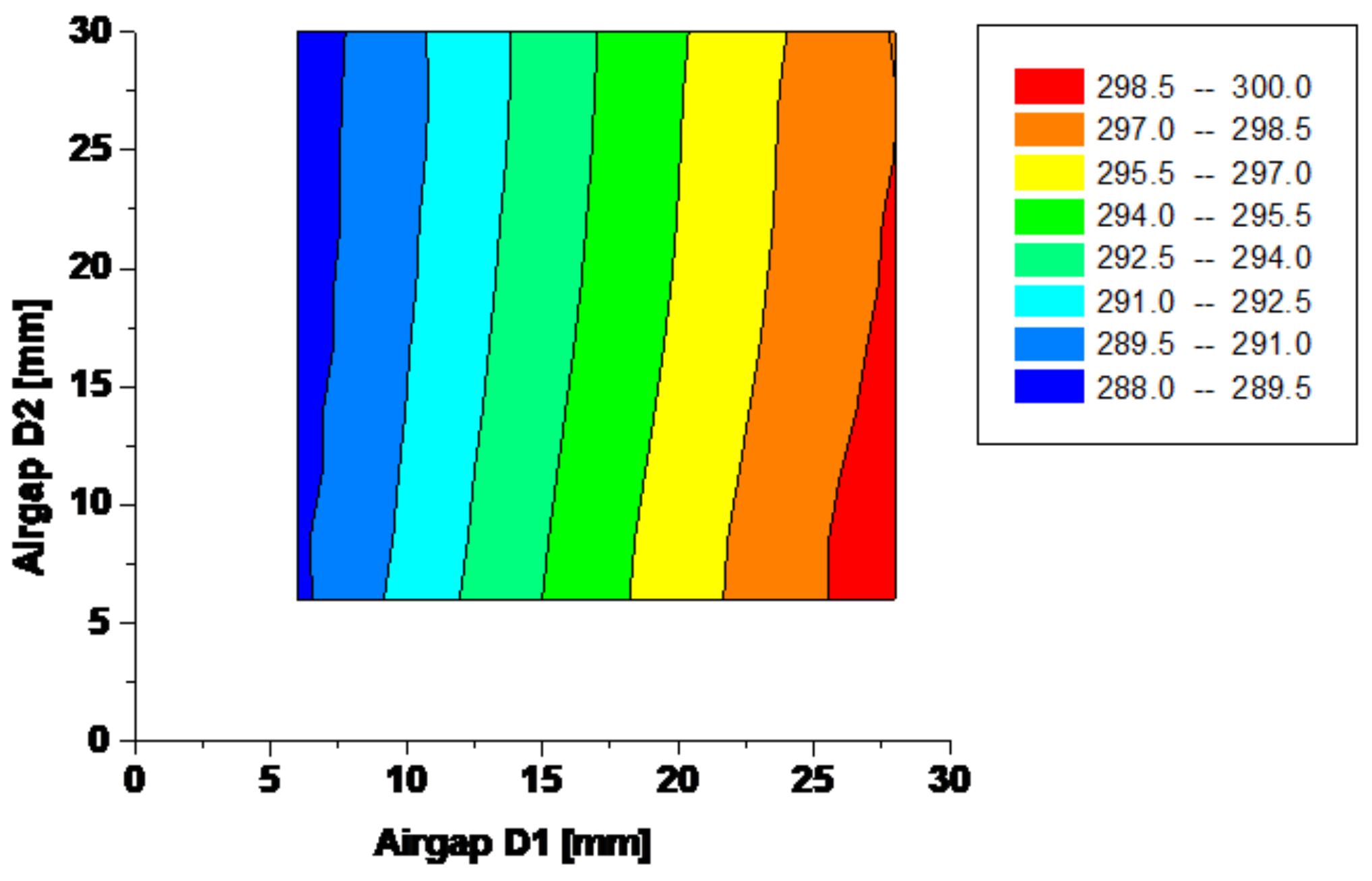
3. Effect of Airgaps D1 and D2

The airgap between the inductor core and the rail head in a low-frequency eddy current rail heater can have a significant impact on the heating efficiency and performance of the heater. This gap refers to the distance between the surface of the rail head and the surface of the inductor core. One of the main effects of the airgap is on the distribution of the magnetic field. The presence of an airgap can cause the magnetic field to become non-uniform, leading to uneven heating of the rail. This can result in hot spots or cold spots along the length of the rail, which can affect the overall heating efficiency and potentially cause damage to the rail. Moreover, a larger airgap can also lead to a decrease in the heating efficiency of the eddy current heater. This is because a larger gap means that a larger portion of the magnetic field is not in direct contact with the rail, resulting in a decrease in the amount of heat generated. On the other hand, a smaller airgap can lead to better heat transfer between the inductor core and the rail head, resulting in more efficient heating. However, if the gap becomes too small, it can lead to an increase in the magnetic flux density, which can potentially cause overheating and damage to the rail. In the following plots, the effect of airgaps D1 and D2 has been examined (Figure 5 and Figure 6). As should have expected, maximum induced power and minimum current are obtained when the airgaps are set at the lower values, but their influence on objectives is limited.
The analysis has been performed assuming for the other parameters the following values: frequency = 50 [Hz]; D3 = 0 [mm]; voltage = 220 [V].

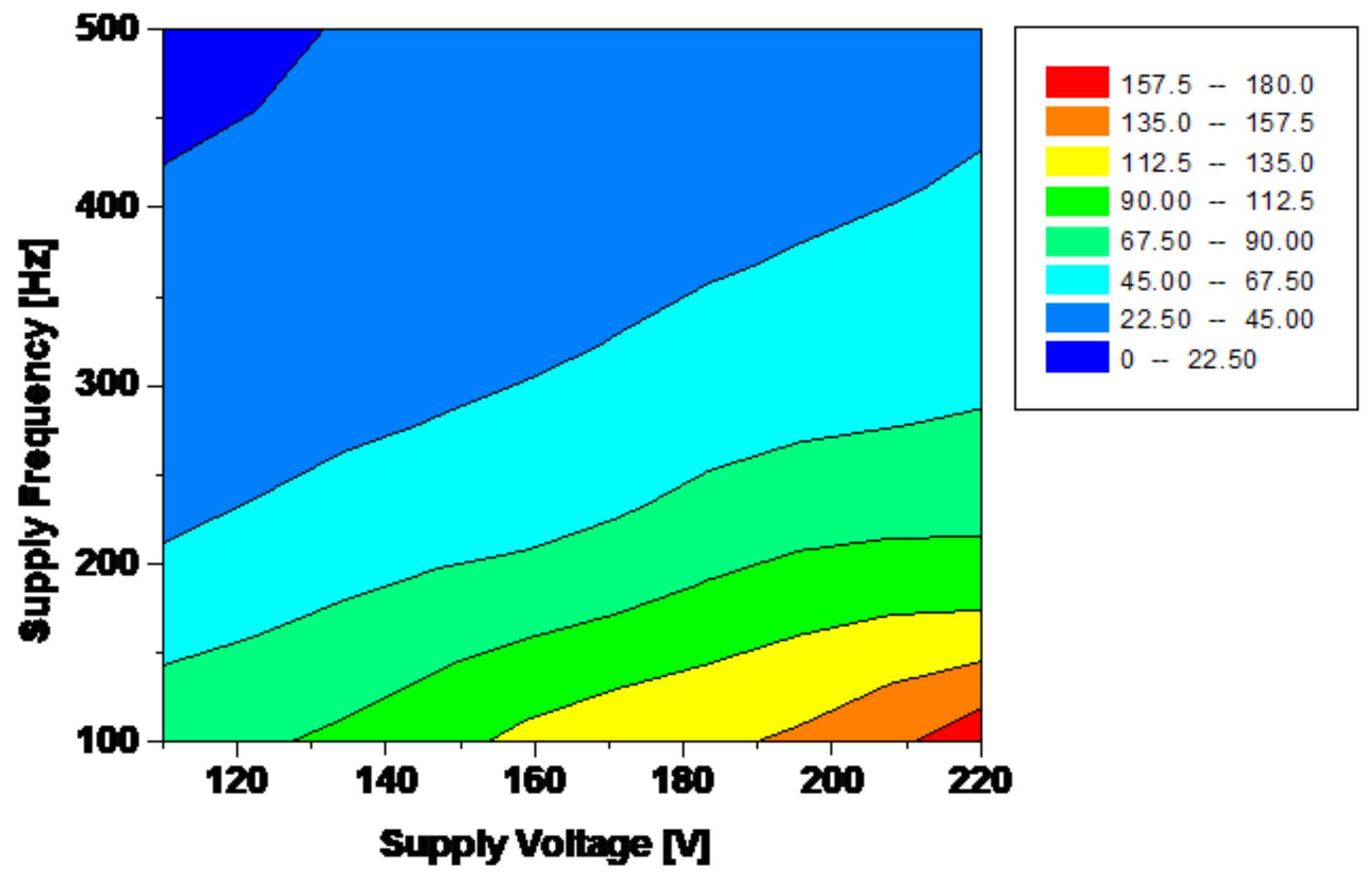
3.1. Effect of Voltage and Frequency Supply

Electrical parameters strongly influence device performances. The voltage and frequency supply of a low-frequency eddy current rail heater also have a significant impact on its performance and efficiency (Figure 7 and Figure 8). The voltage determines the strength of the current flowing through the coil and therefore affects the heating power of the rail heater. Higher voltages can result in a stronger magnetic field and more concentrated current, leading to higher heating efficiency. Similarly, the frequency of the alternating current supply also affects the heating performance of the rail heater. As mentioned earlier, higher frequencies result in a thinner skin depth and more concentrated current near the surface of the rail. This can lead to more efficient heating and a more uniform distribution of heat along the rail [16]. However, it is important to note that there is a limit to how high the voltage and frequency can be increased before it becomes detrimental to the performance of the rail heater. Excessive voltage can cause overheating and damage to the rail, while very high frequencies can lead to energy losses and reduced heating efficiency. Therefore, it is crucial to carefully select the voltage and frequency supply for a low-frequency eddy current rail heater during the optimisation process. This involves finding a balance between achieving high heating efficiency and avoiding any potential negative effects on the performance of the heater. In addition, the voltage and frequency supply must also be compatible with the power source being used for the rail heater. This may require additional considerations and adjustments during the optimisation process. In particular, by increasing voltage supply, the absorbed current, the magnetic flux, and thus the induced power increase, while increasing frequency, keeping constant supply voltage, the reactance winding increases and the absorbed current and induced power decrease. Regulation of voltage and frequency is a strategy to optimise device performances and to control the heating rail in order to take into account different weather conditions.
The analysis has been performed assuming for the other parameters the following values: D1 = 7 [mm]; D2 = 7 [mm]; D3 = 0 [mm].

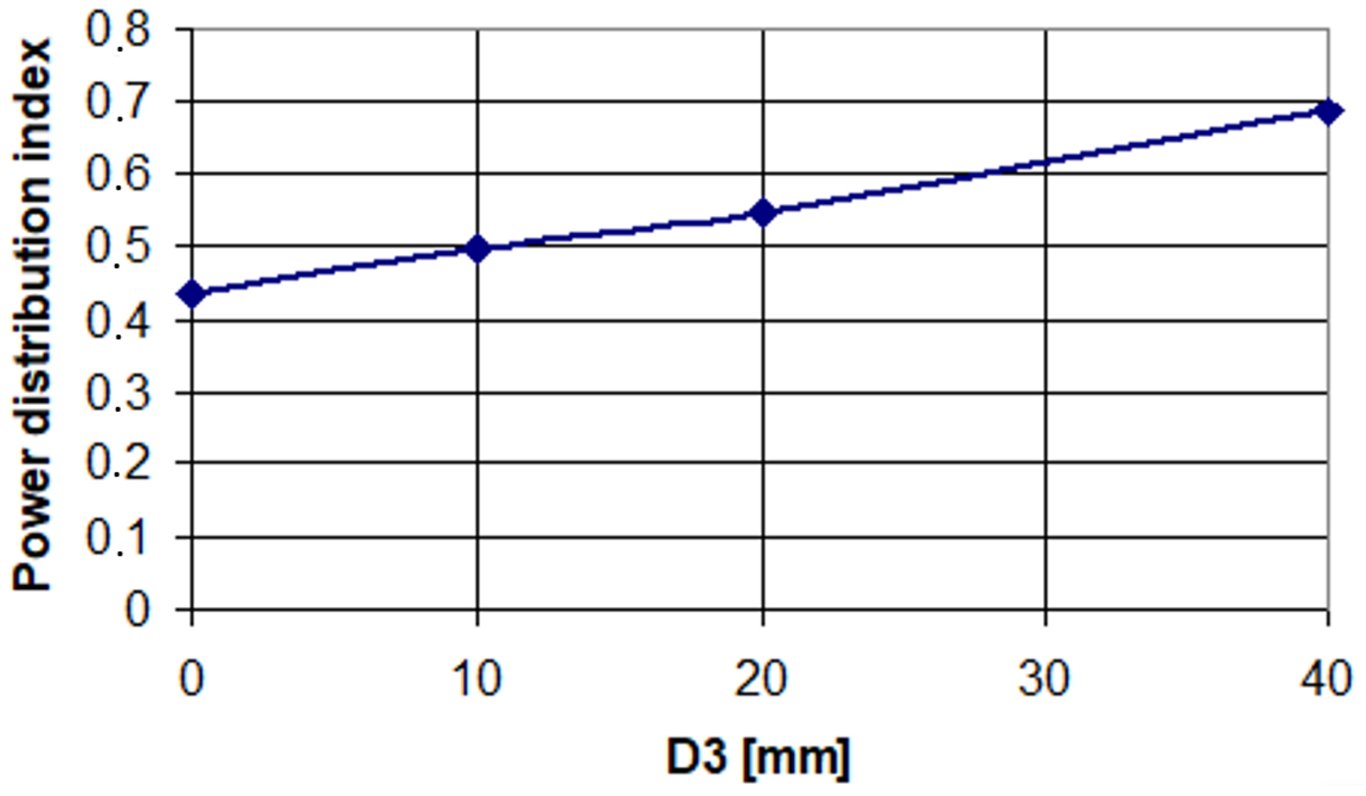
3.2. Effect of Core Vertical Position

The core, which is the central part of the coil, is responsible for generating the magnetic field that induces eddy currents in the rail (Figure 9). The position of the core within the coil affects the distribution of this magnetic field and therefore impacts the heating efficiency of the rail heater. If the core is too close to the rail, the magnetic field may be too concentrated, resulting in localised overheating and potential damage to the rail. On the other hand, if the core is too far away, the magnetic field may not be strong enough to induce sufficient eddy currents and provide efficient heating. Therefore, finding the optimal vertical position for the core is crucial for achieving maximum heating efficiency while avoiding any potential negative effects on the rail. This can be determined through simulations and testing during the optimisation process. In addition, the vertical position of the core may also affect the overall size and shape of the coil, as well as its proximity to other components or structures. These factors must also be taken into consideration during the design. Dropping the inductor core, induced power in the rail foot is increased, while in the rail head, it is decreased (Figure 9), improving power distribution (Figure 10), but globally, the total heating power increases. Unfortunately, magnetic reluctance and thus magnetising current increased (Figure 11).
The analysis has been performed assuming for the other parameters the following values: D1 = 7 [mm]; D2 = 7 [mm]; voltage = 220 [V]; frequency = 50 [Hz].

4. Objective Behaviours versus Parameters

The parameter analysis gives important information on objective behaviours versus parameter optimisation. A brief description of the obtained results is reported in the following Table 1.
Different symbols indicate the effect of the increase in the parameter on the considered objectives:
  • ↑ increase in the objective (high influence of the corresponding parameter);
  • ↗ increase in the objective (small influence of the corresponding parameter);
  • ↓ decrease in the objective (high influence of the corresponding parameter);
  • ↘ decrease in the objective (small influence of the corresponding parameter);
  • − constant (the objective is practically independent of the corresponding parameter).
The most evident consideration of the above analysis is that optimisation objectives are more influenced by electrical than geometrical factors. Voltage and frequency play an important role in improving device performances and the possibility of varying supply conditions is the way to regulate heating intensity to take into account different weather conditions.

5. Optimisation Procedure

An optimisation procedure tailored for the design of electromagnetic devices has been adopted. Fuzzy logic is employed in order to define a normalised quality index for each objective, by a considered membership function. Fuzzy logic is a mathematical approach that allows for the optimisation of complex systems by considering multiple input variables and their relationships. In the design of a low-frequency eddy current rail heater, there are several parameters that need to be optimised, and their relationships can be difficult to define using traditional methods. Fuzzy logic provides a systematic approach to optimising these parameters, taking into account their uncertainties and interdependencies. A single global satisfactory degree is then obtained using the min operator. In this way, the multi-objective problem is reduced to a scalar optimisation performed by Rosenbrock algorithm. In this application, fuzzy sets are chosen, as reported in the plot of Figure 12.
Initial and final device performances and corresponding satisfactory degree are reported in Table 2. From this table, it is possible to see that the initial configuration presents a high inductor current (due to the strong magnetising component) and an induced power in the rail which can be reduced. At the end of the optimisation, a reasonable value of the inductor current is reached to the detriment of the acceptable worsening of induced power and of distribution index.
The use of fuzzy logic in the optimisation of a low-frequency eddy current rail heater offers several benefits, including the following:
  • Handling Uncertainty: Fuzzy logic allows for the consideration of uncertainties in the input variables, which is often the case in real-world systems. This ensures that the optimised design is robust and can perform well under varying conditions.
  • Incorporating Expert Knowledge: Fuzzy logic allows for the incorporation of expert knowledge and experience in the optimisation process. This can lead to more accurate and effective results compared to purely numerical approaches.
  • Consideration of Interdependencies: Fuzzy logic takes into account the interdependencies between input variables, which may not be easily defined using traditional methods. This results in a more comprehensive and accurate optimisation process.

6. Discussion

The optimisation design of a low-frequency eddy current rail heater is an important consideration in ensuring efficient and effective heating of rails. The obtained results from the optimisation design of a low-frequency eddy current rail heater can affect the cracking in several ways. For example, the optimisation design can lead to a more efficient heating process, which may reduce the likelihood of cracking due to excessive heat or temperature gradients. A well-designed low-frequency eddy current rail heater can provide better temperature control, minimising the risk of thermal stress and cracking in the heated material. This can help prevent localised hot spots and potential cracking. In other contexts, such as the detection of cracks, low-frequency eddy current (LFEC) methods have been investigated. The optimisation of the LFEC system design can improve the effectiveness of crack detection, which is crucial for preventing further propagation and potential failure [30]. In this section, the key factors that need to be considered in optimising the design of such a heater will be discussed. The first factor to consider is the frequency of the eddy currents generated by the heater. Low-frequency eddy currents are typically used for rail heating, as they are more effective in penetrating the rail material and generating heat. However, the frequency needs to be optimised to ensure that the heating is uniform across the entire length of the rail. This can be achieved by adjusting the frequency and power of the heater to match the properties of the rail material. Another important factor to consider is the supply voltage, which is related to the value of current to be injected into the inductor. Other important parameters are the shape and size of the heater. The heater needs to be designed to fit snugly around the rail and provide even heating along its length. The shape of the heater can be optimised using simulation software to ensure that it provides maximum coverage and minimises any hot spots or cold spots along the rail. Therefore, the objective of this work was to discuss the design considerations, optimisation parameters, and techniques for achieving efficient and effective heating of railway rails using low-frequency eddy currents. The core geometry was identified and the system was designed to be positioned during the construction of the railway line. A similar work in the literature [16] discusses the possibility of applying low-frequency current to heat railway rails during track laying. It analyses the temperature distribution in the rail as a function of the parameters of the heating inductor and its location. The investigation considers only slowly varying magnetic fields below 300 Hz and formulates practical design rules for the use of inductive heating for track laying.

7. Conclusions

In this paper, a design optimisation of an eddy current rail heater is presented. The optimisation is performed by a procedure based on fuzzy logic and optimisation objectives are determined by means of an FEM code. The optimisation has been devoted to the improvement of electrical performances, such as induced power and inductor current. Particular care has been devoted to the FEM model in order to take into account important phenomena such as complex geometry, eddy current distribution, and non-linear magnetic behaviour of core and rail. The initial configuration is characterised by a sufficient value of induced power in the rail (concentrated in the head of the rail) but a high current is absorbed. The optimisation leads to an intensive reduction in the inductor current, with a limited decrease in induced power and in its distribution inside the rail. The next step of this work will be the direct optimisation of primary quantities, such as temperature distribution, coupling the thermal problem to the field analysis.

Author Contributions

Conceptualization, A.C., M.T. and M.Q.; Methodology, A.C., M.T. and M.Q.; Validation, A.C., M.T. and M.Q.; Writing—original draft, A.C., M.T. and M.T.; Writing—review & editing, A.C., M.T. and M.Q. All authors have read and agreed to the published version of the manuscript.

Funding

This research received no external funding.

Data Availability Statement

Not applicable.

Conflicts of Interest

The authors declare no conflict of interest.

References

  1. Al-Douri, Y.K.; Tretten, P.; Karim, R. Improvement of railway performance: A study of Swedish railway infrastructure. J. Mod. Transp. 2016, 24, 22–37. [Google Scholar] [CrossRef]
  2. Nash, C. Rail infrastructure charges in Europe. J. Transp. Econ. Policy (JTEP) 2005, 39, 259–278. [Google Scholar]
  3. Palin, E.J.; Stipanovic Oslakovic, I.; Gavin, K.; Quinn, A. Implications of climate change for railway infrastructure. Wiley Interdiscip. Rev. Clim. Change 2021, 12, e728. [Google Scholar] [CrossRef]
  4. Lidén, T. Railway infrastructure maintenance—A survey of planning problems and conducted research. Transp. Res. Procedia 2015, 10, 574–583. [Google Scholar] [CrossRef]
  5. Ebersohn, W. Implementing a railway infrastructure maintenance system. In Proceedings of the Conference on Railway Engineering Proceedings: Engineering Innovation for a Competitive Edge, Central Queensland University Rockhampton, Yeppoon, QLD, Australia, 7–9 September 1998; pp. 395–402. [Google Scholar]
  6. Budai-Balke, G. Operations Research Models for Scheduling Railway Infrastructure Maintenance; Number 456; Rozenberg Publishers: Amsterdam, The Netherlands, 2009. [Google Scholar]
  7. Artagan, S.S.; Bianchini Ciampoli, L.; D’Amico, F.; Calvi, A.; Tosti, F. Non-destructive assessment and health monitoring of railway infrastructures. Surv. Geophys. 2020, 41, 447–483. [Google Scholar] [CrossRef]
  8. Andrusca, M.; Adam, M.; Dragomir, A.; Lunca, E.; Seeram, R.; Postolache, O. Condition monitoring system and faults detection for impedance bonds from railway infrastructure. Appl. Sci. 2020, 10, 6167. [Google Scholar] [CrossRef]
  9. Canova, A.; Gruosso, G.; Quercio, M. Characterization of electromagnetic device by means of spice models. Int. J. Emerg. Technol. Adv. Eng. 2021, 11, 12–22. [Google Scholar] [CrossRef]
  10. Mirković, N.; Brajović, L.; Popović, Z.; Todorović, G.; Lazarević, L.; Petrović, M. Determination of temperature stresses in CWR based on measured rail surface temperatures. Constr. Build. Mater. 2021, 284, 122713. [Google Scholar] [CrossRef]
  11. Xiangyu, D.; Liqiang, Z.; Zujun, Y.; Xining, X. The verification of rail thermal stress measurement system. Period. Polytech. Transp. Eng. 2020, 48, 45–51. [Google Scholar] [CrossRef]
  12. Lin, L.; Liu, X.; Zhang, T. Performance investigation of heating terminals in a railway depot: On-site measurement and CFD simulation. J. Build. Eng. 2020, 32, 101818. [Google Scholar] [CrossRef]
  13. Oh, H.S.; Park, C.B.; Lee, S.H.; Lee, J.B.; Kim, T.H.; Lee, H.W. A study on de-icing for railway turnouts using 250 kHz–200 W-class induction heating system. AIP Adv. 2019, 9, 125229. [Google Scholar] [CrossRef]
  14. Szychta, E.; Szychta, L.; Luft, M.; Kiraga, K. Application of 3D Simulation Methods to the Process of Induction Heating of Rail Turnouts. In Infrastructure Design, Signalling and Security in Railway; IntechOpen: London, UK, 2012. [Google Scholar]
  15. Oh, H.S.; Kim, D.K.; Hong, S.M.; Ryu, S.G.; Park, C.B.; Lee, J.B.; Lee, J.; Lee, H.W. Anti-icing System on Railway Turnouts using Induction Heating Technology for Energy Saving. In Proceedings of the 2022 IEEE 21st Mediterranean Electrotechnical Conference (MELECON), Palermo, Italy, 14–16 June 2022; pp. 342–347. [Google Scholar]
  16. Miedzinski, B.; Okraszewski, Z.; Szymanski, A.; Kristiansen, M. Low frequency inductive heating of a rigid track during track laying. In Proceedings of the IAS’95, Conference Record of the 1995 IEEE Industry Applications Conference 30th IAS Annual Meeting, Orlando, FL, USA, 8–12 October 1995; Volume 3, pp. 1903–1909. [Google Scholar]
  17. Ravaee, R.; Hassani, A. Fracture mechanics determinations of allowable crack size in railroad rails. J. Fail. Anal. Prev. 2007, 7, 305–310. [Google Scholar] [CrossRef]
  18. Fry, G.T.; Jones, H.L.; Jones, S.L. Residual stress effects in railroad rail fatigue. In Fatigue and Fracture Mechanics: 29th Volume; ASTM International: West Conshohocken, PA, USA, 1999. [Google Scholar]
  19. Szychta, L.; Szychta, E.; Kiraga, K. Efficiency of Induction Heating of Rails with Oblong Heaters. In Proceedings of the Telematics in the Transport Environment: 12th International Conference on Transport Systems Telematics, TST 2012, Katowice-Ustroń, Poland, 10–13 October 2012; Springer: Berlin/Heidelberg, Germany, 2012; pp. 328–333. [Google Scholar]
  20. Degtyarev, S.; Skoblo, T.; Sapozhnikov, V. A study and development of technology for surface induction hardening of railroad rails from low-alloy steel. Met. Sci. Heat Treat. 1998, 40, 477–481. [Google Scholar] [CrossRef]
  21. Żelazny, R.; Jabłoński, P.; Szczegielniak, T. Operation of the Prototype Device for Induction Heating of Railway Turnouts at Various Operating Frequencies. Energies 2021, 14, 476. [Google Scholar] [CrossRef]
  22. Hong, S.Y.; Kim, D.K.; Oh, H.S.; Lee, J.B.; Park, C.B.; Lee, B.S.; Lee, H.W. Development of PFC Converter for Induction Heating System in Railway. In Proceedings of the 25th IEEE International Conference on Electrical Machines and Systems (ICEMS), Chiang Mai, Thailand, 29 November–2 December 2022; pp. 1–4. [Google Scholar]
  23. Wu, L.; Wen, Z.; Li, W.; Jin, X. Thermo-elastic–plastic finite element analysis of wheel/rail sliding contact. Wear 2011, 271, 437–443. [Google Scholar] [CrossRef]
  24. Tarawneh, C.M.; Fuentes, A.A.; Wilson, B.M.; Cole, K.D.; Navarro, L. Thermal analysis of railroad bearings: Effect of wheel heating. In Proceedings of the Joint Rail Conference, Pueblo, CO, USA, 4–5 March 2009; Volume 43383, pp. 193–204. [Google Scholar]
  25. Canova, A.; Chiampi, M.; Chiarabaglio, D.; Ragusa, C.S.; Repetto, M.; Zucca, M. An advanced electromagnetic code for the analysis and design of electromechanical apparatuses. WIT Trans. Eng. Sci. 1999, 22, 85–97. [Google Scholar]
  26. Bassily, A.M.; Colver, G.M. Modelling and performance analysis of an electric heater. Int. J. Energy Res. 2004, 28, 1269–1291. [Google Scholar] [CrossRef]
  27. Bosshard, R.; Iruretagoyena, U.; Kolar, J.W. Comprehensive Evaluation of Rectangular and Double-D Coil Geometry for 50 kW/85 kHz IPT System. IEEE J. Emerg. Sel. Top. Power Electron. 2016, 4, 1406–1415. [Google Scholar] [CrossRef]
  28. Li, Y.; Wang, Q.; Chen, S.; Lei, Y.; Dai, Y.; Ni, Z.; Hu, X. Quench Protection Design of an 8-T Magnet Built With Low- and High-Temperature Superconducting Coils. IEEE Trans. Appl. Supercond. 2012, 22, 4705907. [Google Scholar] [CrossRef]
  29. Bang, J.; Kim, J.; Lee, J.T.; Kim, G.; Park, J.; Park, S.H.; Noguchi, S.; Hahn, S. A customized electric heater to mitigate screening current by optimal control on temperature distribution in a high-temperature superconductor coil. J. Appl. Phys. 2022, 132, 183911. [Google Scholar] [CrossRef]
  30. Yang, G.; Tamburrino, A.; Zeng, Z.; Deng, Y.; Liu, X.; Udpa, L.; Udpa, S.S. Low frequency EC-GMR detection of cracks at ferromagnetic fastener sites in thick layered structure. AIP Conf. Proc. 2013, 1511, 480–487. [Google Scholar]
Figure 1. Device structure.
Energies 16 07427 g001
Figure 2. Zoom of the mesh near the rail head.
Energies 16 07427 g002
Figure 3. Magnetic field distribution.
Energies 16 07427 g003
Figure 4. Geometrical parameters.
Energies 16 07427 g004
Figure 5. Induced power in the rail [W].
Energies 16 07427 g005
Figure 6. Supply current [A].
Energies 16 07427 g006
Figure 7. Induced power in the rail [W].
Energies 16 07427 g007
Figure 8. Supply current [A].
Energies 16 07427 g008
Figure 9. Induced power in the different parts of the rail vs. vertical core position.
Energies 16 07427 g009
Figure 10. Power distribution index versus vertical core position.
Energies 16 07427 g010
Figure 11. Supply current versus vertical core position.
Energies 16 07427 g011
Figure 12. Membership functions.
Energies 16 07427 g012
Table 1. Objective behaviours versus parameters.
Max. Induced PowerMin. Supply CurrentMax. Power Distribution Index
Airgap D 1
Airgap D 2
Airgap D 3
Voltage
Frequency
Table 2. Device performance.
Initial ValuesInduced Power [W]
Satisfactory Degree
Supply Current [A]
Satisfactory Degree
Power Distribution Index
Satisfactory Degree
Airgap D 1 = 7 [mm]
Airgap D 2 = 7 [mm]4709289.20.41
Airgap D 3 = 0 [mm]
Supply voltage = 220 [V]0.85450.0550.795
Supply frequency = 50 [Hz]
Final ValuesInduced Power [W]
Satisfactory Degree
Supply Current [A]
Satisfactory Degree
Power Distribution Index
Satisfactory Degree
Airgap D 1 = 6 [mm]
Airgap D 2 = 6 [mm]39222090.35
Airgap D 3 = −11 [mm]
Supply voltage = 320 [V]0.4610.4550.575
Supply frequency = 110 [Hz]
Disclaimer/Publisher’s Note: The statements, opinions and data contained in all publications are solely those of the individual author(s) and contributor(s) and not of MDPI and/or the editor(s). MDPI and/or the editor(s) disclaim responsibility for any injury to people or property resulting from any ideas, methods, instructions or products referred to in the content.

