Abstract
Compared with typical mono-facial photovoltaic (PV) solar modules, bifacial solar modules can make full use of reflected or scattered light from the ground and the surroundings to yield more electrical energy. The electrical energy on the rear side depends on multiple factors, such as the IV parameters of modules, packaging materials, and installation circumstances. In this work, the power generation output is simulated and researched using the PV-SYST software program, based on the different electrical parameters of bifacial solar modules and the installation conditions of the given PV systems. The influencing factors that affect the electrical energy are further analyzed using power-loss diagrams. The results show that improving the surface albedo can raise additional energy by 8.3%, thus behaving significantly better than the mono-facial module. Furthermore, improving the siting height and incidence angle modifier (IAM) of the modules can increase the additional energy by 3.1%. In contrast, adjusting the output current or voltage of the modules adds some energy, while the modules are of the same nominal power value. It was observed that the energy level of a photovoltaic system mainly depends on the installation circumstances, but the electrical parameters of the modules themselves contribute little.
1. Introduction
At present, the main support for energy needs still relies on thermal power, such as coal, oil, or natural gas, but all of them are viewed as non-renewable sources of energy. The reserves of fossil energy sources worldwide are 40 years for oil, 60 years for natural gas, and 200 years for coal in 2002 [1,2]. Therefore, exploiting novel renewable energy sources is extremely urgent. Solar energy, outstanding for its unlimited storage capacity and produced without toxic emissions, has received considerable attention.
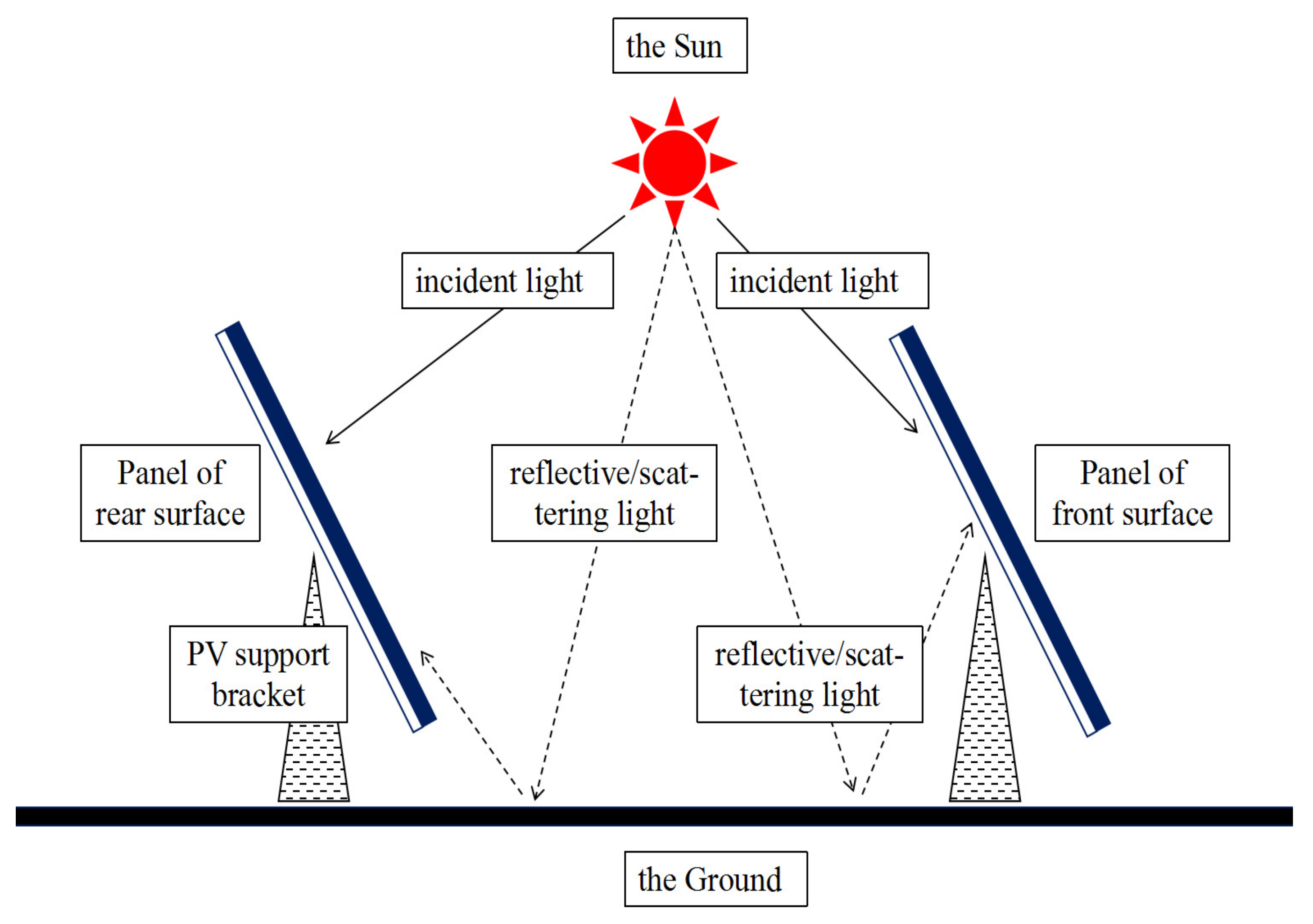
Bifacial solar modules have long been regarded as an effective way to increase power generation by utilizing diffused, scattered, and reflected light, yet mass production has been boosted since 2016. The passivated emitter and rear contact (PERC) structure allows local silicon–metal contact; so, it is more suitable for “double-sided” photon-electron conversion, rather than the standard BSF (back surface field) structure. Meanwhile, unlike the mono-facial module with a TPT (Teldar/polyethylene terephthalate/Teldar) back sheet on the rear side, the bifacial module is replaced by a glass or transparent back sheet, which increases the potential of utilizing the beam irradiation reflected from the ground and improves its general reliability, as shown in Figure 1.

Figure 1.
Comparison of the light utility of bifacial and mono-facial modules: (a) bifacial module; (b) mono-facial module.
Known as the first-generation double-sided solar cell, the PERC structure is also deemed a mature bifacial structure, which ensures a bifacial factor higher than 75% on the cell level by optimizing the finger distribution and passivation quality. Combined with glass and suitable aluminum frames on the rear side, the bifacial factor is able to maintain about 70% on the module level. Taking the influence of the surface albedo into account, bifacial modules usually have a 5–15% increase in power generation compared to mono-facial modules based on the same power level [3,4]. The bifacial factor is thought to be a key factor resulting in reduced balance of system (BOS) costs, thereby achieving a lower levelized cost of energy (LCOE). Thus, the ITRPV (International Technology Roadmap for Photovoltaic) predicts that the proportion of bifacial modules in the PV market will double to 60% within five years [5].
Considering that the electrical performance of bifacial modules has been ever-increasing in recent years with the novel types of systems, more attention needs to be paid to the outdoor working characteristics of high-power bifacial modules on the generation system level.
In recent years, to make full use of bifacial solar cells or modules, the power gains from the rear side have been comprehensively researched through experimental and simulation studies [6,7,8]. From the perspective of the fabrication stages, the power output of the bifacial module is affected by the cell’s performance, such as the bifacial factor [9,10]; module performance, such as patterned glass or light-guidance films [11,12,13]; as well as system installation and orientation parameters, such as the tilt angle, altitude, azimuth angle, and albedo of the ground [14,15,16,17,18,19]. In addition to the traditional perspectives, the weather is also a factor under investigation [20].
The majority of photovoltaic workers are more focused on bifacial PV modules with the same front-side power, and a higher bifacial factor can generate more electrical energy under the same system installation conditions, due to the higher conversion efficiency of the rear side. However, the difficulty of taking advantage of the extra power gains arises from how to balance the benefits between the front- and rear-side power levels of the same bifacial modules, because the way that leads to the high output power of the rear side may reduce the output power of the front side; therefore, there is a need for the optimization of cell structure and encapsulation design [11]. The energy yield gain of the glass/glass bifacial module was about 6% during the period of investigation by applying the lattice pattern on the rear glass due to the optical loss in the cell-gap area.
However, it is not easy to optimize the cell structure and encapsulation material design of the module. Changing the cell structure and encapsulation materials generally leads to manufacturing or reliability problems. Therefore, it is more important to optimize and improve power generation from the aspects of system design and module selection. It is much simpler to change the installation spacing height and to improve the surface reflectivity compared to changing the cell structure and encapsulation material design. At the same time, it is more economical to use software simulation compared to the experimental output data by building a power station system, because it can save considerable experimental costs and rapidly obtain the transformable output data, which are very popular among many power station designers.
Based on the many comparisons between the simulation and test data on the PV (photovoltaic) system level with universal simulation tools [21,22,23,24,25,26], PV-SYST is the most accepted program to help to calculate the functioning and operation of PV solar systems [3]. This simulation tool facilitates the design of system configurations (module arrays, inverters, and frames) and allows for the evaluation of the yield of power production. The output is based on the built-in measurement application, Meteonorm, which is more dependent on the geographical location of the PV system site. The results may contain several simulation variables that can be displayed in hourly, daily, or monthly values. The “loss diagram” estimates weaknesses in the system design [27]. The PV-SYST software (version 7.2) is very powerful and popular and has many functions other software cannot perform, as mentioned above.
Based on the abovementioned reasons, the influence of the modules’ electrical and system installation parameters on power generation is investigated with an energy-loss diagram using the PV-SYST software system in this work to reduce the loss of power generation due to the mismatch of irradiance and bifacial factors and to guide the power station designers to maximize the power generation.
2. Methods and Modeling Preparation
2.1. Bifacial Cells and Modules
The size of p-type bifacial PERC silicon cells was pseudo-square and 182 mm in length. The bulk Si wafers were processed following the traditional steps: alkaline texturing, POCl3 (phosphorus oxychloride) diffusion, laser-assisted doping, and PSG (phosphorosilicate glass) removing and polishing, AlOx (aluminum oxide) film deposition on the rear side with an SiNx (silicon nitride) film on both sides, laser ablation on the rear side, and regular screen printing on both sides. The cells were designed for 9 busbars and 102 fingers on the front side, and were suitable for half-cutting.
These halved cells were integrated into bifacial half-cut modules. The modules were covered with full-sized anti-reflective coating glass on both sides, which could be effectively utilized for the front incident and rear reflective irradiation. The packing film was highly permittable ethylene-vinyl acetate (EVA). There were three cell substrings, divided by a functional bypass protection diode. The bifacial factor was defined as the ratio of the rear- and front-side power sources of the bifacial modules.
2.2. Simulation Interface Settings
The PV system simulation model was located in Taizhou (32.5° N, 119.9° E), Jiangsu Province, and the average horizontal radiation was 1246.2 W/m2, according to the Meteonorm 8.0 Meteorological Station. The simulation model contained an inverter rated power of 5.0 kW, SUN2000-5HTL-L1 from Huawei Technology Ltd. Company (Shenzhen, China), and PV arrays consisting of 12 modules, each with a rated power of 540 W; the Si-mono LRS-72 HIBD 540 M Bifacial module was obtained from the Longi-solar Technology Ltd. Company (Taizhou, China), for which the data are shown in Table 1. In this paper, the simulation model was designed according to the total module power of 1.1 times the power of the inverter.

Table 1.
Detailed parameters of the module and inverter.
To search the effects of several factors on the power generation of the PV system, the PV system model was set as an infinite-length array installation model because this model permits the simulation of the effects of 2-dimensional multi-row modules.
The PV array was aligned and the module was fixed with a tilt angle of 32° to absorb the maximum amount of solar radiation and match the height of the site location for maximum sun exposure. Based on the different areas, the tilt-angled simulation setting should be chosen for an optimal installation inclination range correspondingly; however, this work selected an inclination setting according to the results of previous studies since the best inclination was not within the scope of this work’s discussion. The optimal tilt angle should be approximately the same as the latitude of the PV system’s location, and previous research has indicated that the increase in the albedo allows for a higher tilt angle, because of more reflected or diffused beams, to be incident on the rear side [18]. Matters are more complicated when considering the zenith and azimuth angles, especially panels with a tracking support bracket.
2.3. Simulation Analyses and Relevant Concepts
The performance ratio (PR) is widely used to evaluate the field performance of PV modules, which is defined as the performance relative to the STC power.
where Yf is the final system yield, Yr is the reference yield, Eout is the energy output, P0 is the rated power of the array, Hi is the in-plane irradiation, and Gi,ref is the irradiance at which P0 is determined [11].
Power loss can be extracted due to multiple variables on the system level. Thus, PV array losses are caused by a module Isc mismatch, module quality, and ohmic wiring, while converter losses are attributed to the threshold power, working condition, battery charge/discharge current efficiencies, and so on. The gross power loss can be listed in the power loss diagram.
Albedo plays a vital role in the energy balance of the Earth’s surface since it defines the rate of absorbed solar radiation [2]. The albedo of the solar module installation site is always considered first, because it is a sensible estimation for small-angle tilted PV system simulations. Moreover, the albedo is the ratio of the radiation reflected from the illuminated surface to the incoming radiation, and the value extends from 0 to 1; therefore, it is influenced by the surface morphology and optical path where the modules are placed. The definition of albedo is the ratio of reflected and incident light.
When the installation state of the PV bifacial module is altered, the light irradiation from the rear side fluctuates clearly. In the PV-SYST software (version 7.2), the view factor model is applied to handle the influence of the total irradiation change on the power production of the module [28].
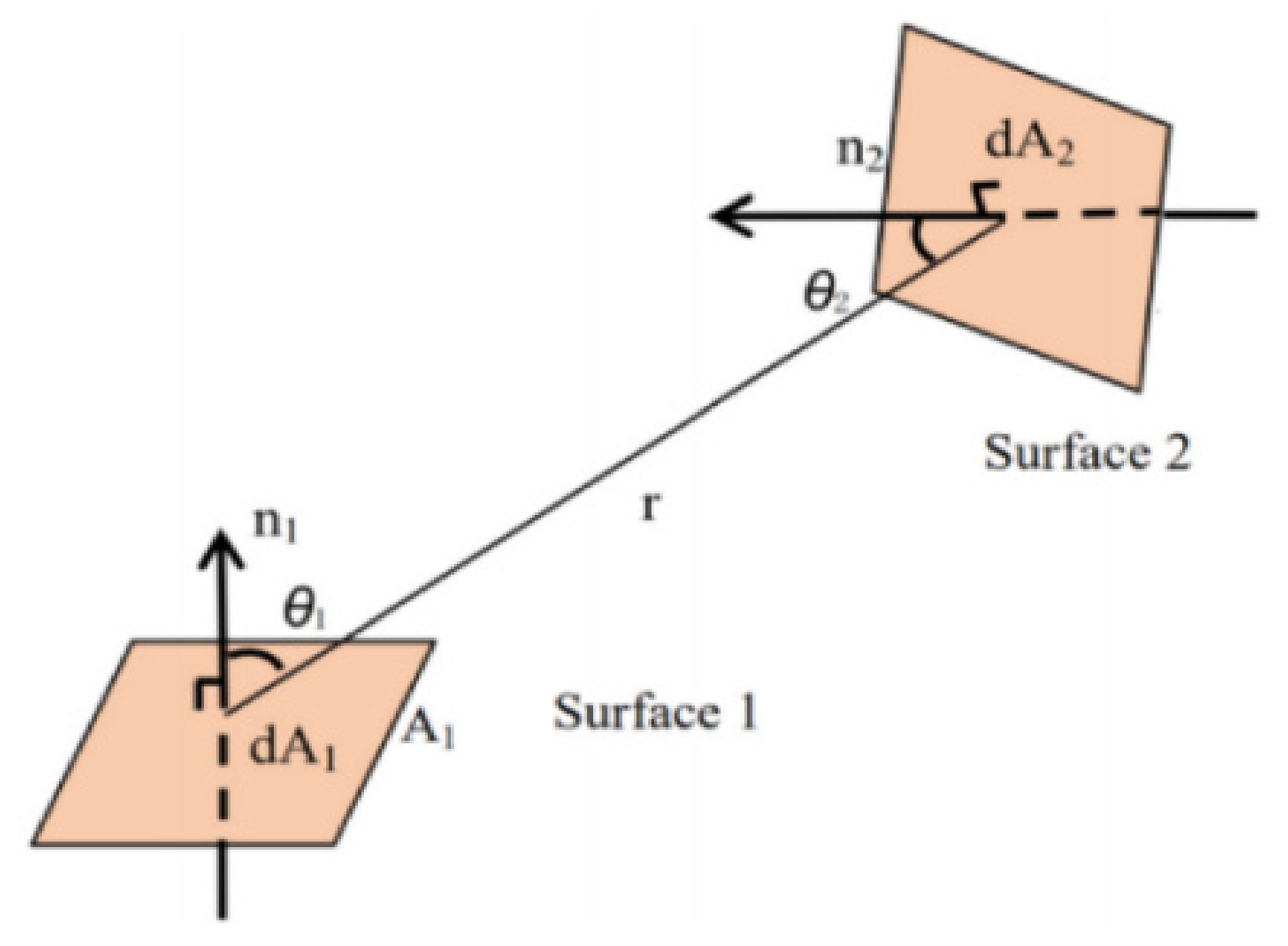
The 2-dimensional view factor model is shown in Figure 2. Assuming that the ground is A1 and the rear surface of the module is A2, the integral F1–2 indicates the proportion of the reflection from A1 can be received by A2, while r is the distance between A1 and A2, and θ is the angle between the line (r) connecting two planes and the normal vector (n) of the plane.
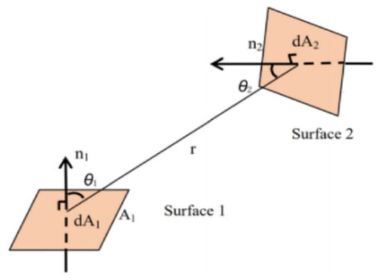
Figure 2.
A brief schematic of the view factor model and estimation [28].
According to the model, it can be concluded that: (i) the view factor rises with larger spacing, which corresponds to the coverage of the rear side of the module, and (ii) the view factor reduces with a greater height, while the total irradiation is increasing.
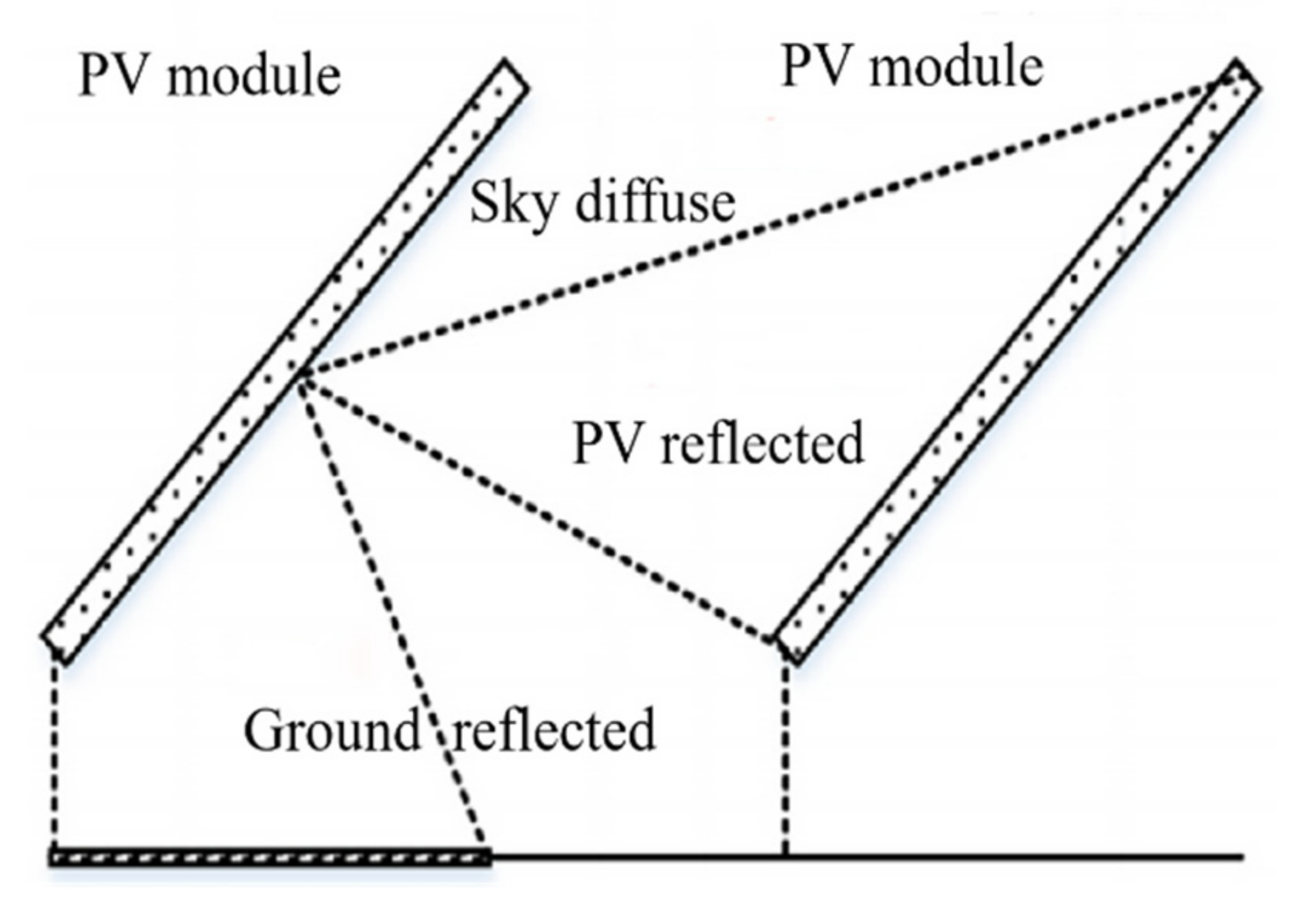
The view factor from the ground to the module should be considered if the installation state of PV module arrays alters. Thus, the ground cover ratio (GCR) was proposed and defined as the coverage of the module on the ground, which could be simplified as the ratio of the module length and spacing between neighbor rows with the same tilt angle. In a regular type of solar system, the module length is consistent with the size; therefore, the GCR is only determined by the spacing. A schematic diagram of the ground reflection is shown in Figure 3.
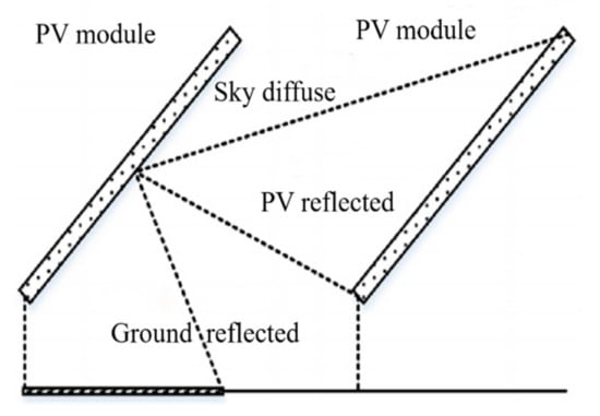
Figure 3.
Schematic diagram of the ground reflection [28].
The bifacial module is superior to sunshine-generated electricity when compared with the so-called mono-facial module. The rear side of the bifacial module is used for receiving light reflected from the ground and scattered from the sky, whereas the latter is deemed as constant. Based on the 2-dimensional view factor module in Figure 2, the view factor diminishes with an increasing module installation elevation, but the summation and uniformity of the reflected light irradiation are greatly affected by a range of panel heights. Thus, the power gain from the rear surface is non-linear. A schematic diagram of the ground reflection for the module installation spacing is shown in Figure 4.
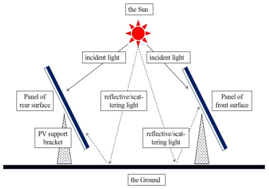
Figure 4.
Schematic diagram of the ground reflection for module installation spacing.
According to IEC 61215, the module power should be measured under the STC (namely, Standard Test Condition: AM1.5, 25 ± 2 °C, 1000 ± 5 W/cm2), and the incident light is perpendicular to the surfaces of the modules. However, the modules received incident light from various angles, IAM (incidence angle modifier) factor, used as the incident angle correction, which was defined as characterizing the impact of the incident angle change on the module power production.
The IAM factor was first adopted in the ASHRAE model, which used a simple empirical formula, only taking the effect of the incident angle (θ) into consideration; therefore, the relative transmittance at the incident angle of 0° was FTB (0). Thus, the transmittance at different angles is shown in the following equation:
where the b0 value is determined by the type of solar cell and module structure, and it can be replaced with a module of a better quality for the same size.
3. Result and Discussion
The necessary parameters, such as the ground surface albedo, installation variables of PV arrays, and inherent variables of PV modules, are discussed in this section. The component of the common bifacial module is shown in Figure 1.
3.1. Effect of Albedo on the System Power Production and Performance Ratio
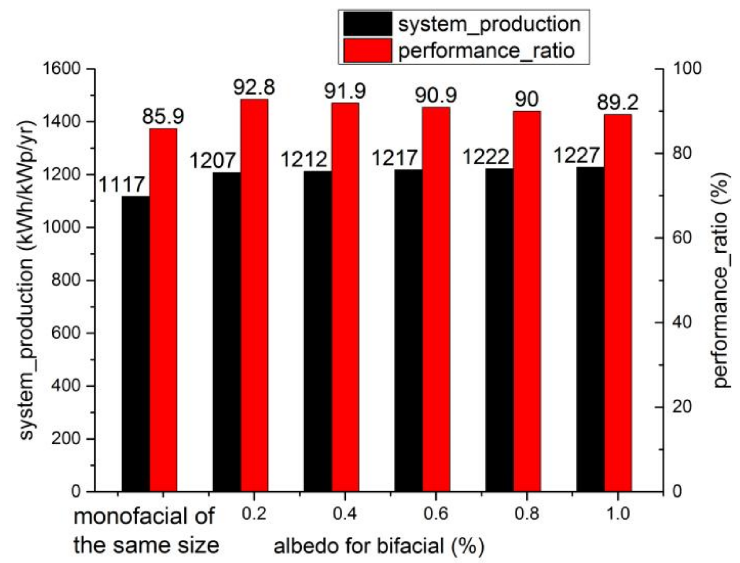
Using the PV-SYST software simulation, adjusting the different albedo values, and then obtaining the power generation and system efficiency data, the trend of the power production and system efficiency with an albedo value ranging from 0 to 0.8 was first observed, as shown in Figure 5. All the simulation output data were based on the aforementioned simulation interface settings as described Section 2 of this paper, except for the different albedo values.
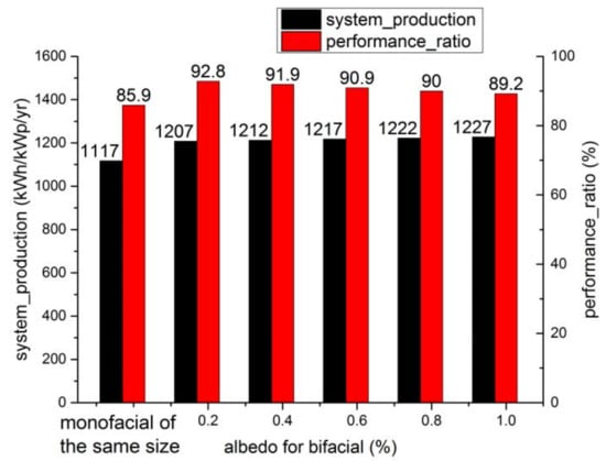
Figure 5.
System production and performance ratio for an increasing albedo.
The albedo value of the PV bifacial modules revealed that extra-light radiation reflected from the ground could be received, which enhanced the additional power generation performance of the PV system, as shown by the black bars. The power generation of the mono-facial module with the same size was simulated to 1117 kWh/kWp/yr, that is, the albedo of 0.8 yielded an 8.3% power gain compared with the mono-facial module of the same type. After comparing the related research result, the 8.3% power gain can be observed to be less than the experimentally reported high-energy-yield gain of 15.25% in a 30 kW bifacial PV system with different ground surfaces based on an albedo value of 0.65 [3]. For the other case, the other PV system installation conditions (module height, tilt angle, spacing, etc.) should be considered and optimized for the maximum power generation gain from the PV system design. The output gain of the albedo change for different installation conditions was not exactly the same.
For instance, the extra power generation observed after comparing mono-facial and bifacial solar PV systems was confirmed because of a higher albedo value on snowy ground [29]. The bifacial modules were even qualified during extreme weather conditions, such as on cloudy days or at a high latitude with high diffusions [30]. Note that the electrical energy of the bifacial module is still affected by scattering from the surroundings; thus, the power of the front-side module is only 1110 kWh/kWp/yr without the scattering effect, i.e., 1% lower than the mono-facial module of the same type. It was speculated that the bifacial module could not sufficiently receive the light reflected from the back glass; instead, the mono-facial module with a white back sheet on the rear side featured the bonus [10]. The most common albedo values in Jiangsu Province are in the 0.1–0.5 range. There are different ground types and surface covers with albedo values. Normally, the albedo value of white paint is 0.8, white stone is 0.8, white cement is 0.7, waterproof coil is 0.7, aluminum foil is 0.55, yellow sand is 0.4, green building is 0.25, and ash cement is 0.35.
After carefully checking the system power production report based on the PV-SYST software simulation output, which contained a system loss flowchart, and each ground reflection parameter had a corresponding PV loss flow-chart, the key data were taken and presented in Table 2. In Table 2, the positive sign indicates the energy gain and the negative sign indicates the energy loss. Similarly, the positive and negative signs in all of tables have the same meaning and are not specifically stated below. It was concluded that the power gain occurred owing to less than a quarter of the ground reflection loss and an additional 1.6% of ground reflection on the front side, as can be observed in Table 2. However, the module array power loss, such as Isc mismatch and reverse leakage of the PN junction, slightly increased with the extra irradiance from the ground; thus, the efficiency of the system was reduced, which is represented by red bars.

Table 2.
The power gain owing to the albedo of the ground.
3.2. Effect of the Bifacial Factor of PV Modules on the System Power Production and Performance Ratio
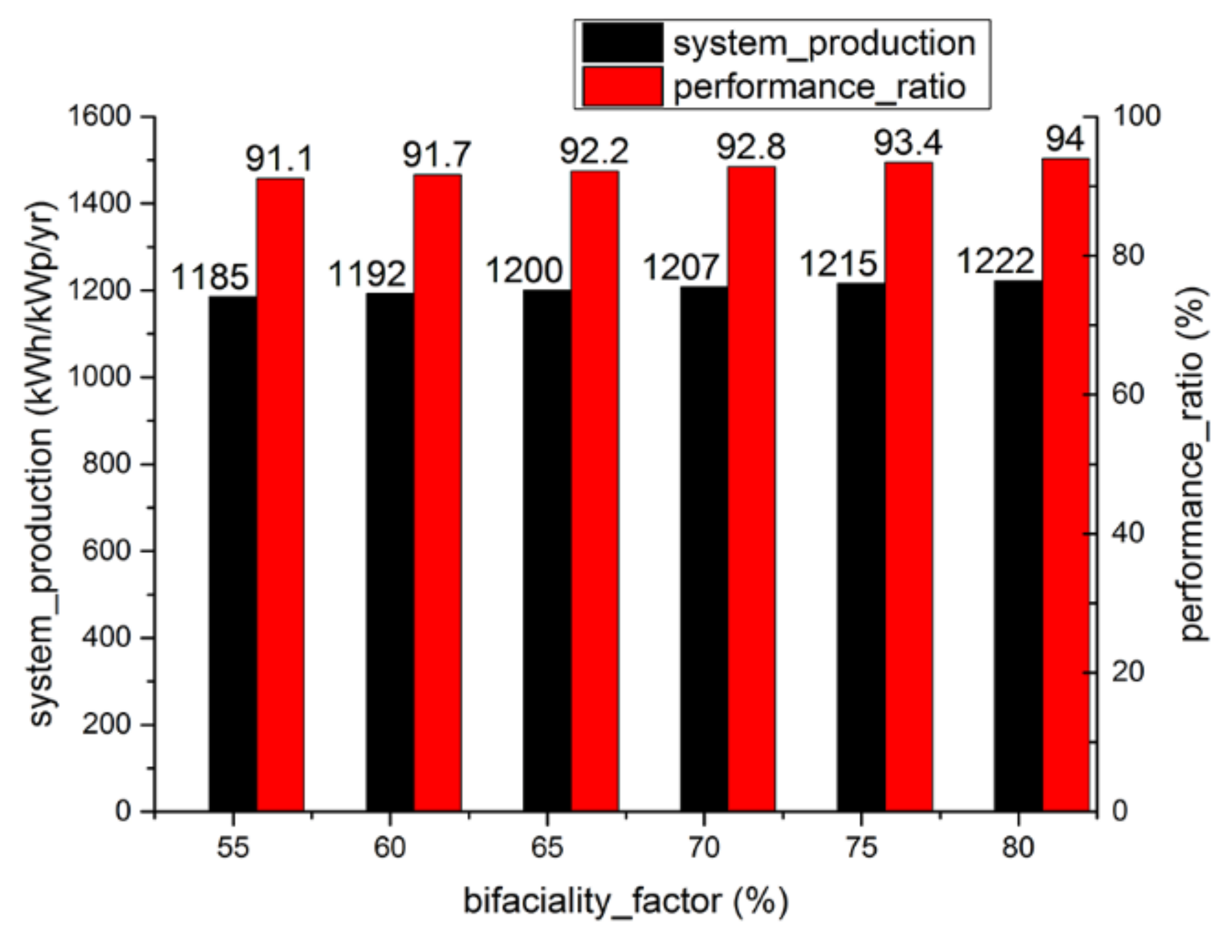
The bifacial factor, the ratio of rear- to front-side module power generation, is the core ability of power generation and is distinct from the mono-facial solar modules. The increase in the bifacial factor of modules is beneficial to exploit the potential of converting solar radiation into electrical energy from the rear side; thus, extra power generation goes along with the variable. By using the PV-SYST software simulation, adjusting the bifacial factor, and then obtaining these power generation and system efficiency data, the trend of the power production and system efficiency with the bifacial factor was first assessed, as shown in Figure 6. Figure 6 reveals that the PV system production and efficiency are both proportionally elevated with an increasing bifacial factor of the PV modules, which can be explained by the fact that a rear-side power yield is expressed as a generation superimposed onto the front side in the PV-SYST software. On the other hand, the PV module array power and system losses both occurred, regardless of the bifacial factor; therefore, the system efficiency was simultaneously improved. A bifacial factor of 0.8 achieved an extra 3.1% of power gain compared with a factor of 0.55.
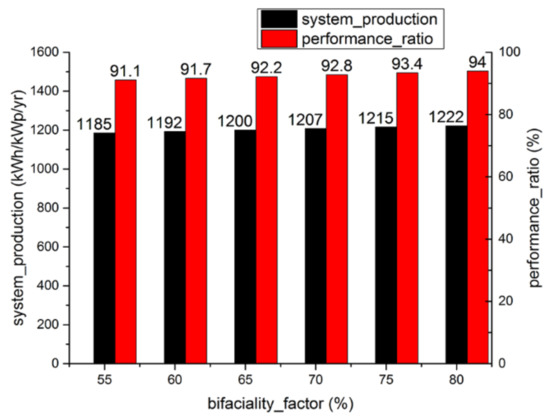
Figure 6.
System production and performance ratio for an increasing bifacial factor ranging from 55% to 80%.
After carefully checking the system power production report with the different bifacial factors based on the PV-SYST software simulation output, which presented a system loss flowchart, including PV loss due to the irradiation level, temperature, mismatch ohmic, etc., these key data were obtained and are presented in Table 3. Moreover, Table 3 shows that all proportions of irradiance values from the ground and energy loss remain unchanged by simply increasing the bifacial factor from 55% to 80%. The constant PV loss due to the irradiance level was 1.1%, the PV loss due to temperature was 4.4%, the mismatch loss was 3.3%, the ohmic loss was 0.8%, and the IAM loss was 2.6% because of the algorithm of total yielding results on both sides in the PV-SYST software. The only observable improvement was the array energy.

Table 3.
The power gain owing to the bifacial factor of the module.
3.3. Effect of the Ground Cover Ratio (GCR) on the System Power Production and Performance Ratio
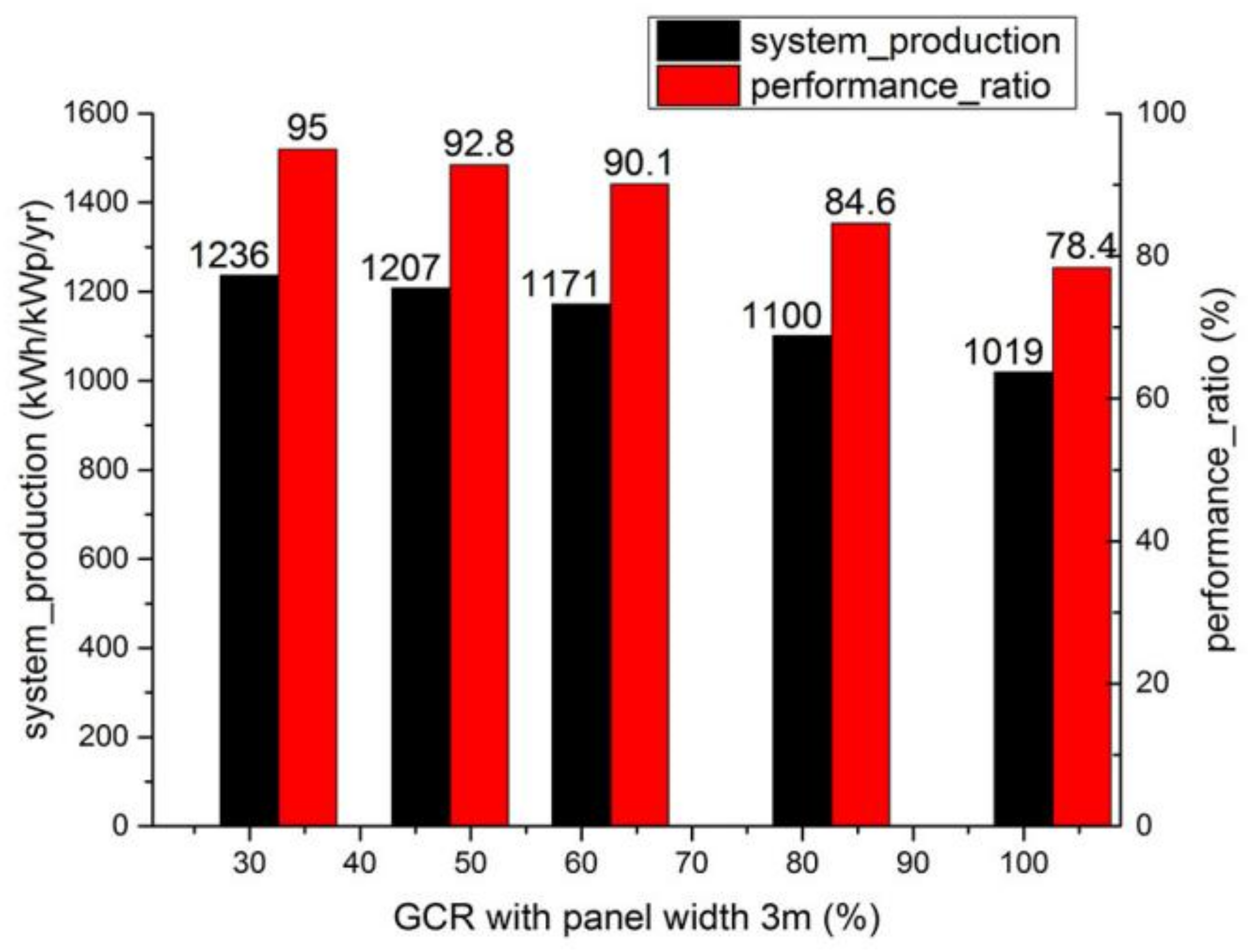
The PV-SYST software simulation was conducted based on the aforementioned simulation interface settings, as described Section 2 of this paper, except for the different spacings, and is depicted the curves presented in Figure 7, illustrating the PV system production and efficiency changes with different spacings. It can be implied that the system production and efficiency seem stable while the GCR is less than 50%, because more beams are reflected from the ground with a larger view factor.
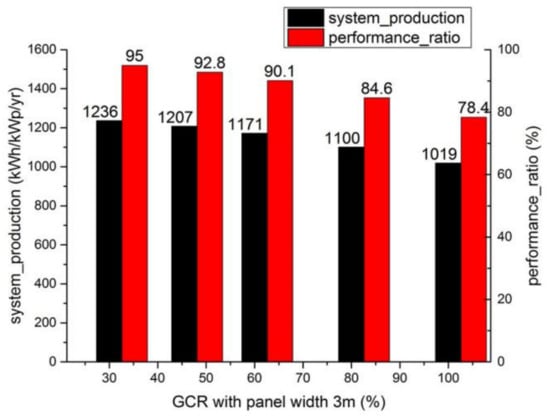
Figure 7.
System production and performance ratio for an increasing GCR.
After carefully checking the system power production report with the increasing GCR based on the PV-SYST software simulation output, which contained a system loss flowchart, including PV loss due to irradiation loss, these key data were obtained and presented in Table 4 below. From the energy loss diagram shown in Table 4, the reduction in “near shading:irradiance loss” is thought to be the reason for an improvement in the array energy, and it corresponds to the addition of the view factor on the rear side from 26.1% to 69.6%, which is extracted from the bifacial system definition.

Table 4.
The power gain owing to a growing GCR.
The GCR of 0.3 achieved an extra 21.3% of power gain compared with the factor of 1; hence, it seemed like an outstanding way to make full use of the potential of bifaciality. However, for a lower GCR, the spacing must be large enough with the same module size; therefore, the actual economic benefits should be compromised.
3.4. Effect of the Installation Height of PV modules on the System Power Production and Performance Ratio
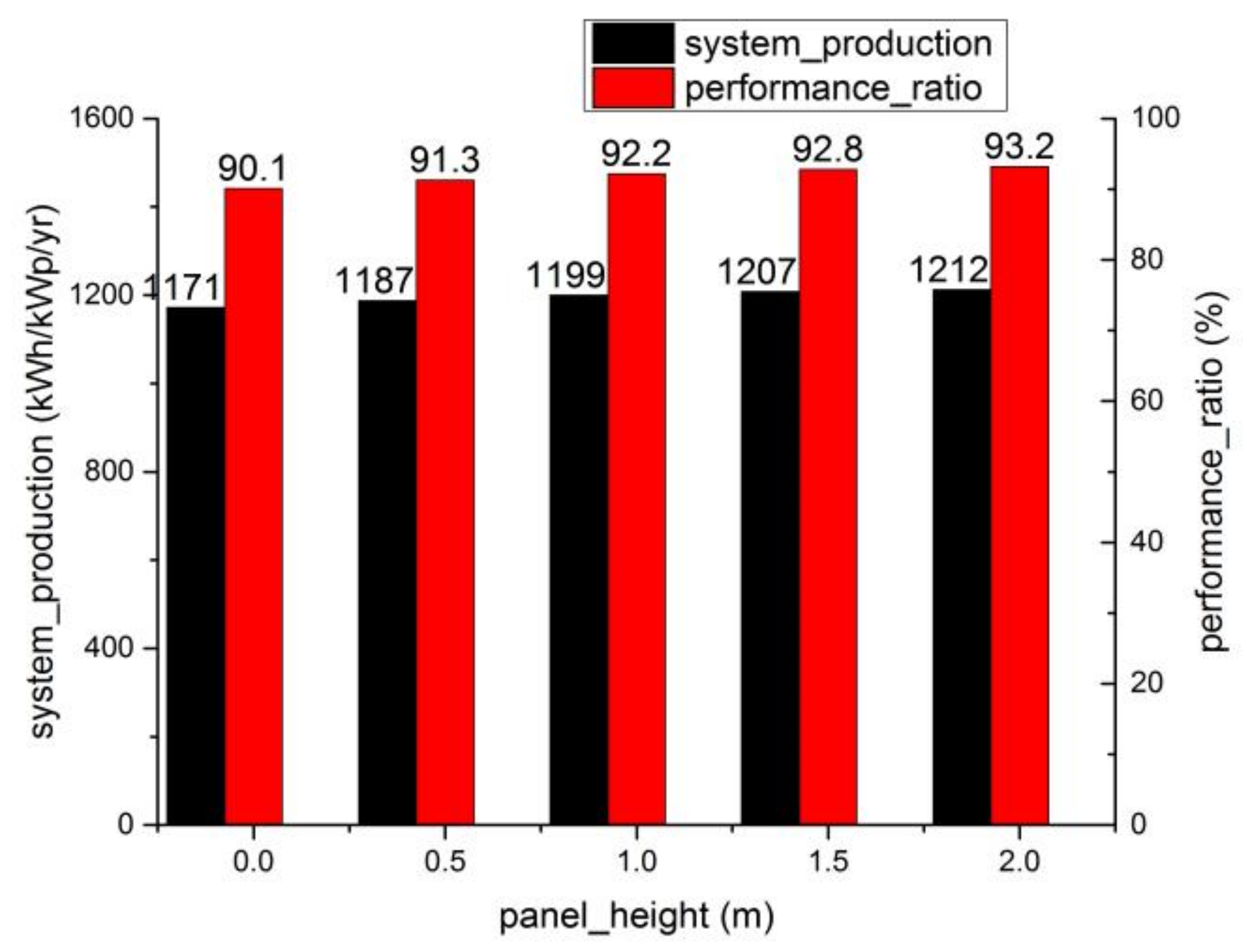
By the PV-SYST software simulation, adjusting the module height and then obtaining these power generation and system efficiency data, the trend of the power production and system efficiency in addition to module height was first assessed, as shown in Figure 8. It can be concluded, from Figure 8, that the system power production from the rear side of the bifacial modules gradually slows down if the installation height exceeds 1.5 m, which is deemed as an optimum figure because of the extra 3.1% power gain compared with the modules (or panels) positioned vertically over the ground. This tendency mainly depended on the effective light on the rear side and the view factor. The former was the function of sky diffusion on the rear side, while the latter was related to the GCR model. Note the latter “view factor” stands for the energy loss according to the GCR model, instead of the basic conception extracted from the bifacial system, as in Table 4.
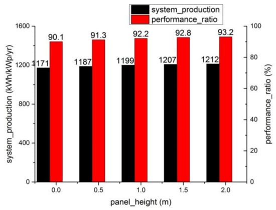
Figure 8.
System power production and performance ratio for an increasing module installation height.
After carefully checking the system power production report with the module installation height based on the PV-SYST software simulation output, which contained a system loss flowchart, these key data were collected and are presented in Table 5. The increasing trend of the extra power gain was mainly affected by the view factor on the rear side, for example, the energy loss could be reduced by 17% with the module installation height elevation ranging from 0 to 1.5 m, as can be observed from the loss analysis list shown in Table 5. It was speculated that the beam irradiation uniformity from the rear side of the modules greatly improved [31], rather than the irradiation reflected from the ground. According to our simulation, it is advised that the irradiance distribution density from the rear side remains almost consistent with a height greater than 1.5 m; thus, it induces the inflection on the power gain.

Table 5.
The power gain owing to the improvement of the module installation height.
Otherwise, the scattering effect of dust on light is reduced with a higher module height, so the modules can receive more incident light. However, the PV-SYST software did not fully take the scattering into account. As a reference [31], L. Kreinin et al. also illustrated that the Isc and power of the bifacial module could increase by 10% and 20%, respectively, based a similar fixed 30° tilt angle and installation elevation angle over 1.0 m, larger than our simulation data. The main reason is that the experiment result is sufficiently concerned with weather conditions. However, in this work, the module’s performance and installation design were the main focus, rather than weather conditions.
3.5. Effect of IAM on System Power Production and Performance Ratio
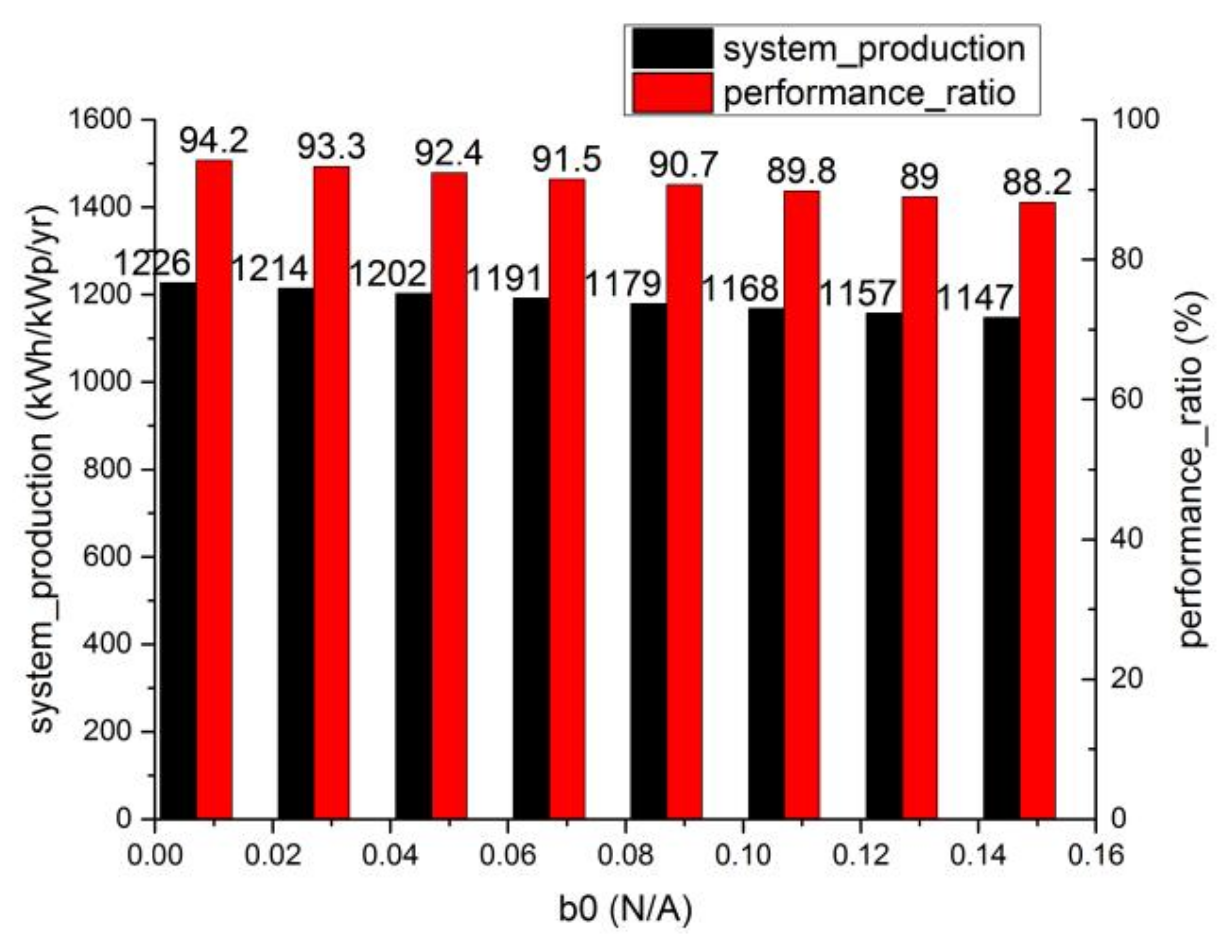
The b0 value of the common solar bifacial module was regarded as 0.03~0.05 according to the PV-SYST software. By the PV-SYST software simulation, adjusting the b0 value then obtaining these power generation and system efficiency data, the trend of the power production and system efficiency was assessed, as shown in Figure 9. The PV system production and efficiency increased with a lower b0 value, as shown in Figure 9, similar to the loss that occurred due to the IAM factor for global reductions. An extra 1.5% power-gain result can be achieved if the module works under ideal conditions, such as preventing impurities inside the glass, or Isc mismatches between the neighbor modules in a series.
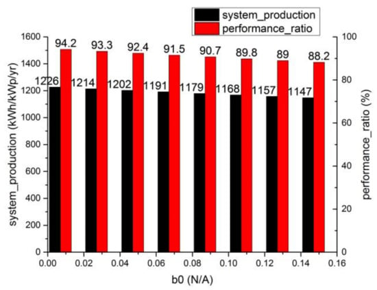
Figure 9.
System power production and performance ratio for an increasing IAM factor.
In the latest version, the IAM model is accessible to the Fresnel model, which is optional for various encapsulants. For example, when modules are coated with anti-reflective or textured glass, the surface is not as smooth as normal glass or plastic; therefore, the incident light is reflected more than once in theory, and the equivalent incident angle is reduced, thus increasing the system power production and performance ratio. We acknowledged a reduction in the energy loss value by 0.4% due to the IAM factor with the anti-reflective glass, as the energy flow shows in Table 6. Therefore, adjustable angle brackets are also recommended to take advantage of the light-trapping effect. After carefully checking the system power production report with the module b0 value based on the PV-SYST software simulation output, which contained a system pow gain flowchart, these key data were collected and presented in Table 7. Table 7 shows the different b0 values corresponding to the different IAM factor loss values.

Table 6.
System power production and performance ratio for different Fresnel models.

Table 7.
The power gain owing to the improvement of the IAM factor.
3.6. Effect of the Temperature Coefficient on the System Power Production and Performance Ratio
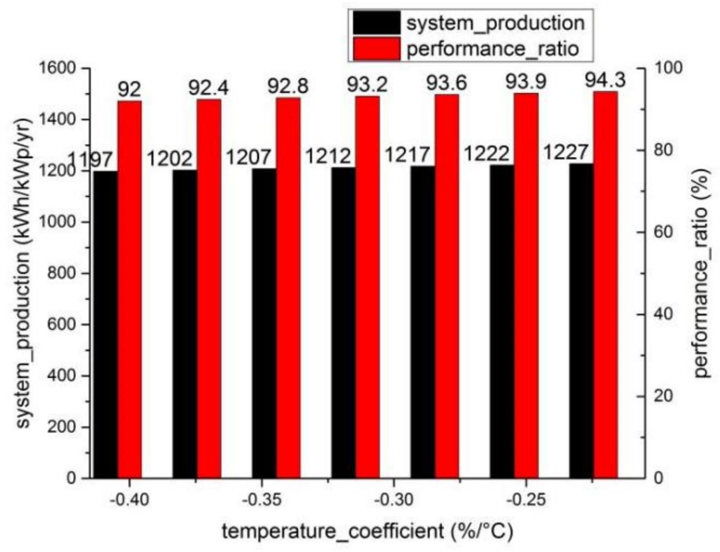
PV solar modules suffer a considerable output voltage drop when functioning outside. This is largely due to the heating effect of the photogenic current, resulting in a mass output power loss. The local heating gradient is also the origin of thermo-mechanical microcracks. The temperature coefficient experiences a power generation decrease by the increasing internal temperature of the module. In the PV-SYST software simulation, adjusting the temperature coefficient of the module and then obtaining these power generation and system efficiency data, the trend of the power production and system efficiency with the temperature coefficient was assessed, as shown in Figure 10. Figure 10 shows that the system power production and performance ratio varies according to the temperature coefficient. Thus, decreasing the temperature coefficient by 0.09%/°C is an ideal method for an extra 1.2% power gain. From Table 8, we can see the different PV losses occurring due to the temperature for the different temperature coefficients. All the data in Table 8 were obtained from the software simulation output report.
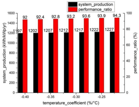
Figure 10.
System power production and performance ratio for the increasing temperature coefficients of the module.

Table 8.
The power gain owing to the increasing temperature coefficient.
A higher system power production and performance ratio was achieved using a module with a lower temperature coefficient, which is usually described as negative. A relatively slow heating rate reduces the waste of actual electric generation. The temperature coefficient of the module in our simulation was −0.34, corresponding to a system efficiency of 92.8% (performance ratio).
3.7. Effect of Merely Altering the Rs inside the Module on the Power Generation and System Efficiency of the PV Solar System
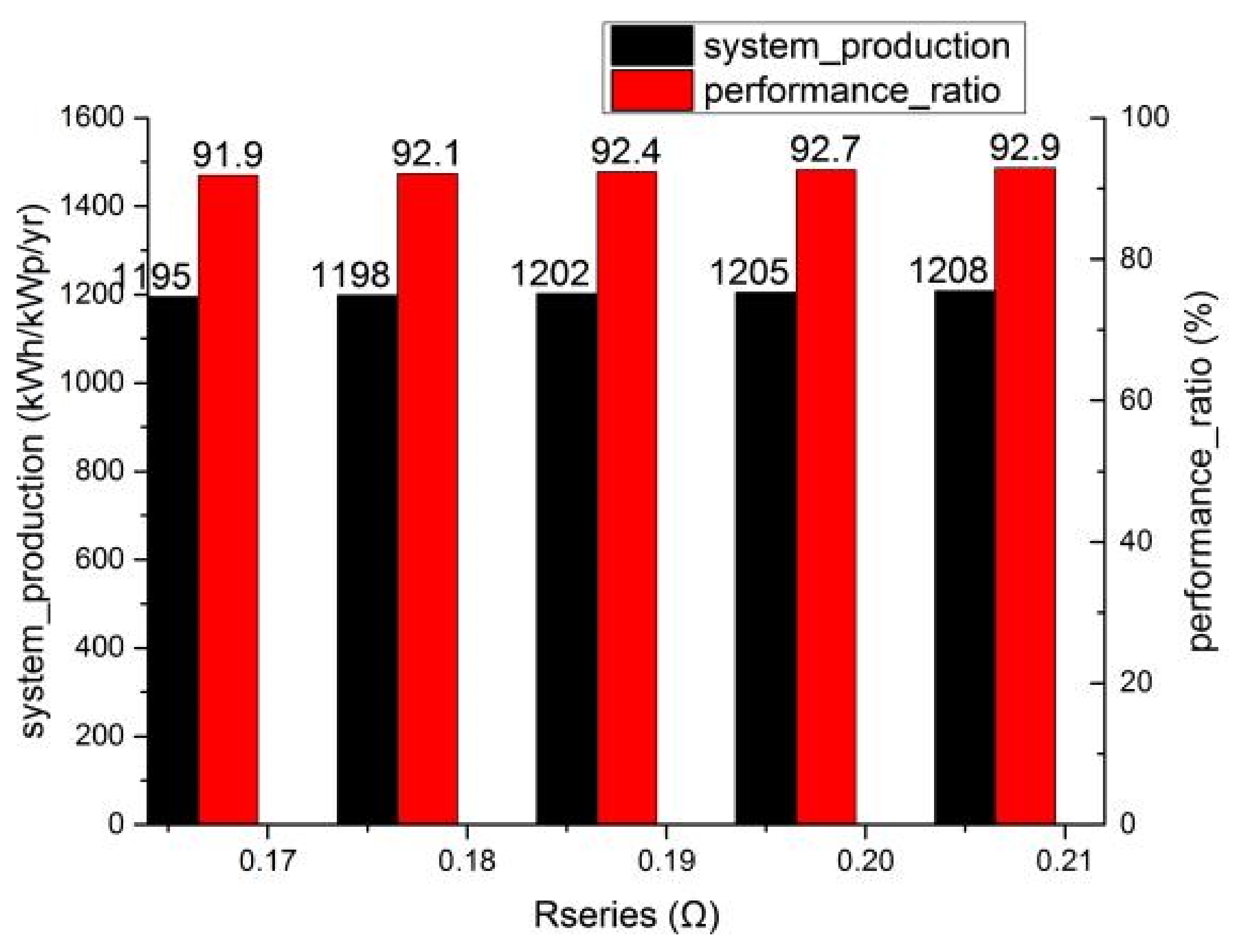
The increase in the series resistance (Rs) value of the PV system is generally divided into two cases, that is, the Rs inside solar modules and that of connection materials, such as electric wires, junction box, etc., and only the former is analyzed here. The former case is dramatically separated into two parts, namely, the increase in the Rs value of the solar cell and that of interconnecting ribbons or strings. On the one hand, as the Rs of the solar cell is independent of the short circuit (Isc), the corresponding open voltage (Voc) of the cell is nearly in direct proportion to an increasing Rs value; on the other hand, the Voc of the solar module also increases after an extra voltage subdivision due to an increase in the ribbon Rs value. According to the PV system model of the PV-SYST software, the former case was handled simply with an increasing Rs value. Thus, the tendencies of the system’s power production and performance ratio followed by an increasing Rs value are plotted in Figure 11, based on the system power production simulation report. All the simulation output data were based on the aforementioned simulation interface settings, as described Section 2 of this paper, except the different Rs value.
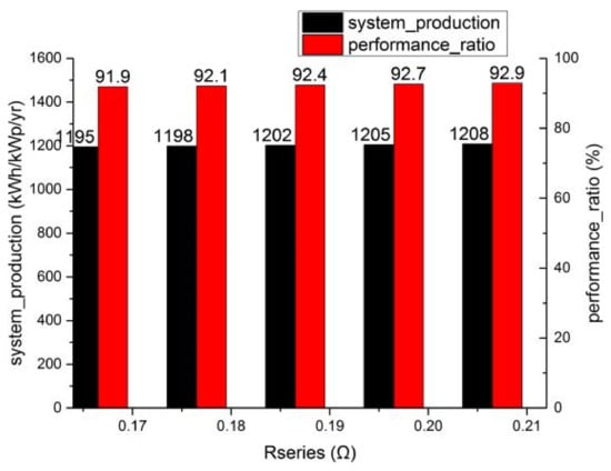
Figure 11.
System production and performance ratio for increasing Rs values.
The system’s power production and performance ratio were improved as the Rs value increased. From the energy flowchart presented in Figure 11, it can be implied that the PV loss due to the irradiance level decreases by 0.8% with the Rs value ranging from 0.168 to 0.208 Ω, which corresponds to an extra 1.0% power gain.
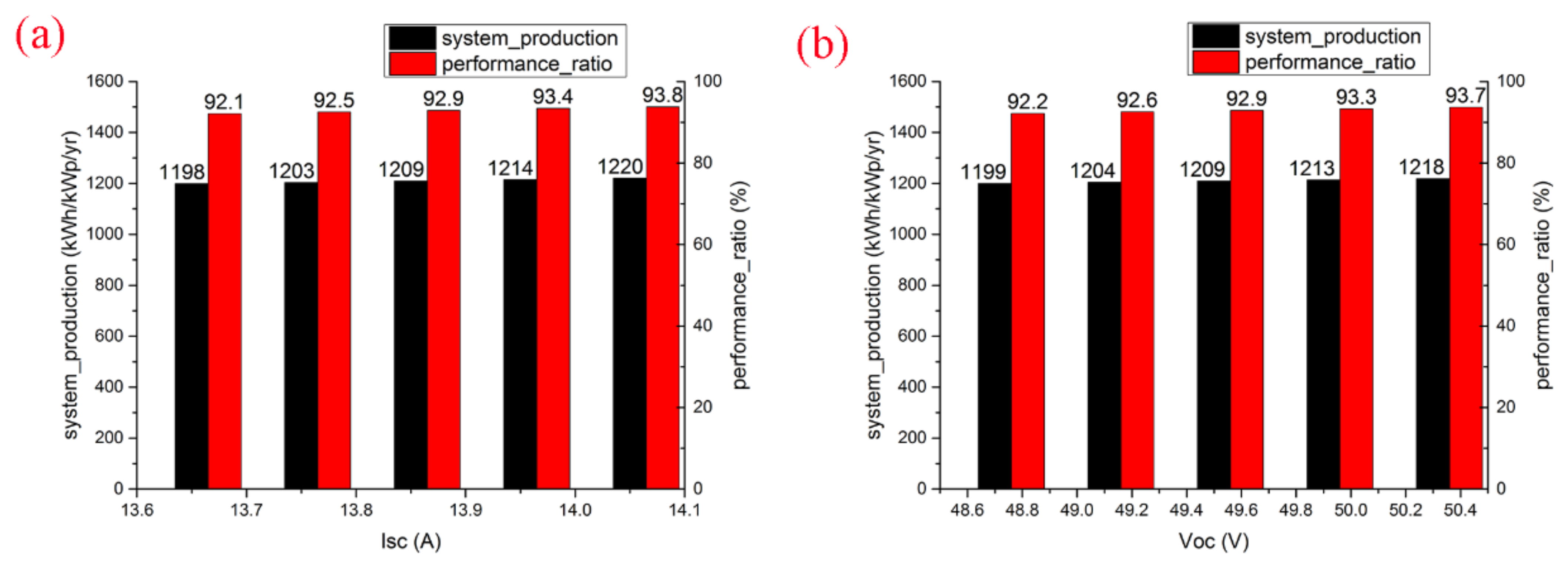
Herein, two special cases were also illustrated. If the module’s Pmpp remains constant, the Rs value inside the module should simultaneously increase while the Isc or Voc values increase. The trend of the power production and system efficiency ratio with the Isc and Voc values remaining constant was assessed, as shown in Figure 12, by adjusting the Isc and Voc values of the module in the PV-SYST software simulation and obtaining the power production and system efficiency data. Figure 12 shows that the PV system production and efficiency values increase with elevated Isc and Voc values. Table 9 shows the different PV losses due to the irradiance levels from the software simulation report for different Rs values. Here, with a higher Rs value, the voltage subdivision of the module was considerably improved, plus elevated Isc or Voc values, as well as the actual power generation, resulting in the system power production and performance ratio increasing further by 1.1%.
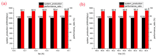
Figure 12.
(a) System production and performance ratio for an increasing Isc value with a constant Pmpp value; (b) system production and performance ratio for an increasing Voc value with a constant Pmpp value.

Table 9.
The power gain owing to an enhancement of the series resistance.
4. Conclusions
This paper studied the influence of module parameters and system conditions on the system’s electrical energy when installing PV systems. Considering that the bifacial module, rather than the mono-facial one, received little reflective light irradiation from the rear glass, the power of the front-side module was about 1% lower than the latter. However, based on the 0.8 albedo of the ground, the bifacial module could increase the energy level by about 8.3%, thus performing significantly better than the mono-facial module.
In addition, the power output can be optimized further in the following ways.
- (1)
- The power output achieves a 3.1% bonus when increasing the bifacial factor of the modules from 55% to 80%;
- (2)
- The power output achieves a 21.3% bonus when reducing the GCR from 1.0 to 0.3 (i.e., broadening the spacing from 3 to 10 m), and it is considered the best improvement;
- (3)
- The power output achieves a 3.1% bonus when increasing the installation height to 1.5 m;
- (4)
- The power output achieves a 1.9% bonus when reducing the b0 value in the ASHRAE model by 0.1; plus, it is an improvement on encapsulants in the Fresnel model;
- (5)
- The power output achieves a 1.2% bonus if decreasing the value of the temperature coefficient by 0.09%/°C;
- (6)
- If the nominal power of the module is kept constant, the energy of the bonus is limited to 2.1%, despite enhancing the output current of the module.
Thus, we suggest that, when installing a PV solar system, the siting conditions of the PV modules should be considered in advance. When the nominal power of the modules is largely fixed, the electrical energy is not greatly affected.
This paper mainly researched and analyze the module output gains and losses achieved by software systems. Limited by its experimental conditions, including the site and capital, the actual power plant system is still in preparation and a comparison of actual power output monitoring and theoretical simulations will be included in our future working plan. Comparing the actual output and simulation results is very meaningful work.
Author Contributions
Conceptualization, C.Z.; Methodology, C.Z. and H.S.; Software, H.L.; Validation, H.L.; Investigation, C.Z. and H.L.; Resources, H.S. and H.L.; Data curation, H.L.; Writing—original draft, C.Z.; Writing—review & editing, C.Z.; Supervision, H.S.; Funding acquisition, H.S. All authors have read and agreed to the published version of the manuscript.
Funding
This work was financially supported by the National Natural Science Foundation of China (61774084), a project supported by the Special Fund of Jiangsu Province for the Transformation of Scientific and Technological Achievements (BA2022204) and the Double Carbon Special Fund of Jiangsu Province (BE2022005) and (BE2022006).
Conflicts of Interest
The authors declare no conflict of interest.
References
- Muhammad, A.A.; Shiddiq, Y.A.M.; Jumadi, T. PVSYST-Based Solar Power Plant Planning. INTEK J. Penelit. 2022, 9, 89. [Google Scholar]
- Tri Kristiyani, R.; Hadi, S.P.; Kusumawanto, A. Energy planning with economic analysis of grid solar power plants in multipurpose building. AIP Conf. Proc. 2023, 7, 030007. [Google Scholar]
- Türkdoğru, E.; Kutay, M. Analysis of albedo effect in a 30-kW bifacial PV system with different ground surfaces using PVsyst software. J. Energy Syst. 2022, 6, 543–559. [Google Scholar] [CrossRef]
- Prasad, M.; Prasad, R. Bifacial vs monofacial grid-connected solar photovoltaic for small islands: A case study of Fiji. Renew. Energy 2023, 203, 686–702. [Google Scholar] [CrossRef]
- Tina, G.M.; Scavo, F.B.; Aneli, S.; Gagliano, A. Assessment of the electrical and thermal performances of building integrated bifacial photovoltaic modules. J. Clean. Prod. 2021, 313, 127906. [Google Scholar] [CrossRef]
- Abe, C.F.; Dias, J.B.; Notton, G.; Faggianelli, G.-A.; Pigelet, G.; Ouvrard, D. Estimation of the Effective Irradiance and Bifacial Gain for PV Arrays Using the Maximum Power Current. IEEE J. Photovolt. 2023, 13, 432–441. [Google Scholar] [CrossRef]
- Raina, G.; Sinha, S. Experimental investigations of front and rear side soiling on bifacial PV module under different installations and environmental conditions. Energy Sustain. Dev. 2023, 72, 301–313. [Google Scholar] [CrossRef]
- Muthu, V.; Ramadas, G. Performance studies of Bifacial solar photovoltaic module installed at different orientations: Energy, Exergy, Enviroeconomic, and Exergo-Enviroeconomic analysis. Environ. Sci. Pollut. Res. 2023, 30, 62704–62715. [Google Scholar] [CrossRef]
- Zhu, Q.; Zhu, C.; Liu, S.; Shen, C.; Zhao, W.; Chen, Z.; Chen, L.; Wang, J.; Wang, L.; Zhang, S.; et al. A model to evaluate the effect of shading objects on the energy yield gain of bifacial modules. Sol. Energy 2019, 179, 24–29. [Google Scholar] [CrossRef]
- Wang, L.; Tang, Y.; Zhang, S.; Wang, F.; Wang, J. Energy yield analysis of different bifacial PV (photovoltaic) technologies: TOPCon, HJT, PERC in Hainan. Sol. Energy 2022, 238, 258–263. [Google Scholar] [CrossRef]
- Yin, H.P.; Zhou, Y.F.; Sun, S.L.; Tang, W.S.; Shan, W.; Huang, X.M.; Shen, X.D. Optical enhanced effects on the electrical performance and energy yield of bifacial PV modules. Sol. Energy 2021, 217, 245–252. [Google Scholar] [CrossRef]
- Zauner, M.; Muehleisen, W.; Holzmann, D.; Baumgart, M.; Oreski, G.; Feldbacher, S.; Feichtner, M.; Nemitz, W.; Leiner, C.; Sommer, C.; et al. Light guidance film for bifacial photovoltaic modules. Renew. Energy 2022, 181, 604–615. [Google Scholar] [CrossRef]
- Jang, J.; Pfreundt, A.; Mittag, M.; Lee, K. Performance Analysis of Bifacial PV Modules with Transparent Mesh Backsheet. Energies 2021, 14, 1399. [Google Scholar] [CrossRef]
- Wang, S.; Wilkie, O.; Lam, J.; Steeman, R.; Zhang, W.; Khoo, K.S.; Siong, S.C.; Rostan, H. Bifacial Photovoltaic Systems Energy Yield Modelling. Energy Procedia 2015, 77, 428–433. [Google Scholar] [CrossRef]
- Yusufoglu, U.A.; Pletzer, T.M.; Koduvelikulathu, L.J.; Comparotto, C.; Kopecek, R.; Kurz, H. Analysis of the Annual Performance of Bifacial Modules and Optimization Methods. IEEE J. Photovolt. 2015, 5, 320–328. [Google Scholar] [CrossRef]
- Duhis, A.H.; Aljanabi, M.; Alkafaji, M.S.S. Increasing photovoltaic system power output with white paint albedo—A scenario in Al-Mausaib City using PVSyst. software. Int. J. Power Electron. Drive Syst. 2023, 14, 1149–1159. [Google Scholar] [CrossRef]
- Ebhota, W.S.; Tabakov, P.Y. Impact of Photovoltaic Panel Orientation and Elevation Operating Temperature on Solar Photovoltaic System Performance. Int. J. Renew. Energy Dev. 2022, 11, 591–599. [Google Scholar] [CrossRef]
- Raina, G.; Sinha, S.; Vijay, R. Study on the optimum orientation of bifacial photovoltaic module. Int. J. Energy Res. 2022, 46, 4247–4266. [Google Scholar] [CrossRef]
- Barbosa, J.D.; Ansari, A.S.; Manandhar, P.; Qureshi, O.A.; Ubinas, E.I.R.; Alberts, V.; Sgouridis, S. Tilt correction to maximize energy yield from bifacial PV modules. Earth Environ. Sci. 2022, 1008, 012008. [Google Scholar] [CrossRef]
- Shiravi, A.H.; Firoozzadeh, M.; Lotfi, M. Experimental study on the effects of air blowing and irradiance intensity on the performance of photovoltaic modules, using Central Composite Design. Energy 2022, 21, 121633. [Google Scholar] [CrossRef]
- Hanaa, M.F.; Emad, A.S.; Mohamed, I.A.; Fathy, A.S. Agricultural Grid Connected Photovoltaic System Design and Simulation in Egypt by using PVSYST Software. WSEAS Trans. Circuits Syst. 2022, 21, 306–315. [Google Scholar]
- Windarta, J.; Handoko, S.; Sukmadi, T.; Nafadinanto, K.; Muqtasida, S.; Halim, C. Design of a solar power plant system for micro, small, medium enterprise uses PVSyst 7.1 as a renewable energy alternative source in remote areas. Earth Environ. Sci. 2022, 969, 012029. [Google Scholar] [CrossRef]
- AlMakhzzom, O.M.; Ahmed, A.A. Design and Evaluation of Solar PV On-Grid Connected Power Plant Using PVsyst Software in Bani Walid Hospital / Libya. Afr. J. Adv. Pure Appl. Sci. 2023, 2, 128. [Google Scholar]
- Mohammadi, S.A.D.; Gezegin, C. Design and Simulation of Grid-Connected Solar PV System Using PVSYST, PVGIS and HOMER Software. Int. J. Pioneer. Technol. Eng. 2022, 1, 36–41. [Google Scholar] [CrossRef]
- Kumar, D.J.V.; Deville, L.; Ritter, K.A.; Raush, J.R.; Ferdowsi, F.; Gottumukkala, R.; Chambers, T.L. Performance Evaluation of 1.1 MW Grid-Connected Solar Photovoltaic Power Plant in Louisiana. Energies 2022, 15, 3420. [Google Scholar] [CrossRef]
- Islam, S.; Islam, F.; Habib, A. Feasibility Analysis and Simulation of the Solar Photovoltaic Rooftop System Using PVsyst Software. Int. J. Educ. Manag. Eng. 2022, 12, 21–32. [Google Scholar] [CrossRef]
- Mohamed, N.; Sulaiman, S.; Rahim, S. Design of ground-mounted grid-connected photovoltaic system with bifacial modules using PVsyst software. J. Phys. Conf. Ser. 2022, 2312, 012058. [Google Scholar] [CrossRef]
- Zhang, Z.; Wu, M.; Lu, Y.; Xu, C.; Wang, L.; Hu, Y.; Zhang, F. The mathematical and experimental analysis on the steady-state operating temperature of bifacial photovoltaic modules. Renew. Energy 2020, 155, 658–668. [Google Scholar] [CrossRef]
- Hayibo, K.S.; Petsiuk, A.; Mayville, P.; Brown, L.; Pearce, J.M. Monofacial vs bifacial solar photovoltaic systems in snowy environments. Renew. Energy 2022, 193, 657–668. [Google Scholar] [CrossRef]
- Gu, W.; Ma, T.; Li, M.; Shen, L.; Zhang, Y. A coupled optical-thermal model of the bifacial PV module. Appl. Energy 2020, 258, 114075. [Google Scholar] [CrossRef]
- Kreinin, L.; Bordin, N.; Karsenty, A.; Drori, A.; Grobgeld, D.; Eisenberg, N. PV module power gain due to bifacial design. Preliminary experimental and simulation data. In Proceedings of the 2010 35th IEEE Photovoltaic Specialists Conference (PVSC), Honolulu, HI, USA, 20–25 June 2010; p. 002171. [Google Scholar]
Disclaimer/Publisher’s Note: The statements, opinions and data contained in all publications are solely those of the individual author(s) and contributor(s) and not of MDPI and/or the editor(s). MDPI and/or the editor(s) disclaim responsibility for any injury to people or property resulting from any ideas, methods, instructions or products referred to in the content. |
© 2023 by the authors. Licensee MDPI, Basel, Switzerland. This article is an open access article distributed under the terms and conditions of the Creative Commons Attribution (CC BY) license (https://creativecommons.org/licenses/by/4.0/).


