Prediction of Dynamic Temperature and Thermal Front in a Multi-Aquifer Thermal Energy Storage System with Reinjection
Abstract
:1. Introduction
2. Heat Transfer Model
- (a)
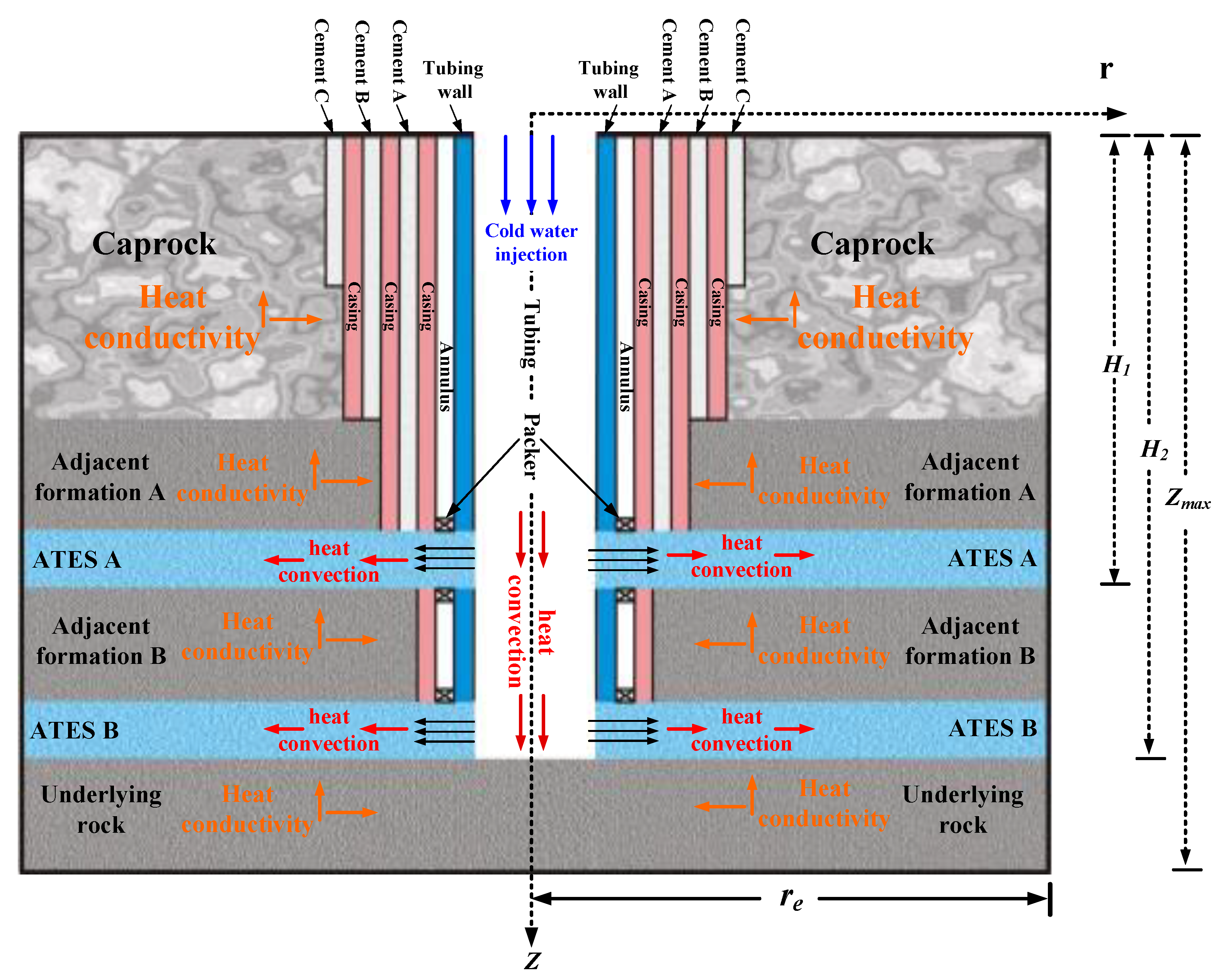
- Undisturbed geothermal temperature of the downhole is a known function of depth, and the vertical borehole radius remains unchanged with depth.
- (b)
- The reinjection well thoroughly penetrates the MATES system, and the fluid flow is steady state.
- (c)
- MATES fluid flows are considered planar radial flow.
- (d)
- Fitting functions of the thermo–physical parameters with different temperatures are suitable for the coupled thermal-hydraulic model.
2.1. Two-Way Fully Coupled Mathematical Model
2.1.1. Heat Transfer Model Inside the Tubing
2.1.2. Heat Transfer Model from the Impermeable Formations to the Tubing Wall
2.1.3. Heat Transfer Model of the MATES System
2.1.4. Initial and Boundary Conditions of the Model
2.1.5. Fluid Thermo–Physical Properties with Different Temperature
2.1.6. Derivation of Hydrodynamic Front and Thermal Front Migration Model
2.2. Model Validation
3. Results and Discussion
3.1. The Advancement Characteristic of the Hydrodynamic Front and Thermal Front
3.2. Monitoring the Hydrodynamic/Thermal Breakthrough via the Temperature Inside the Tubing
- (1)
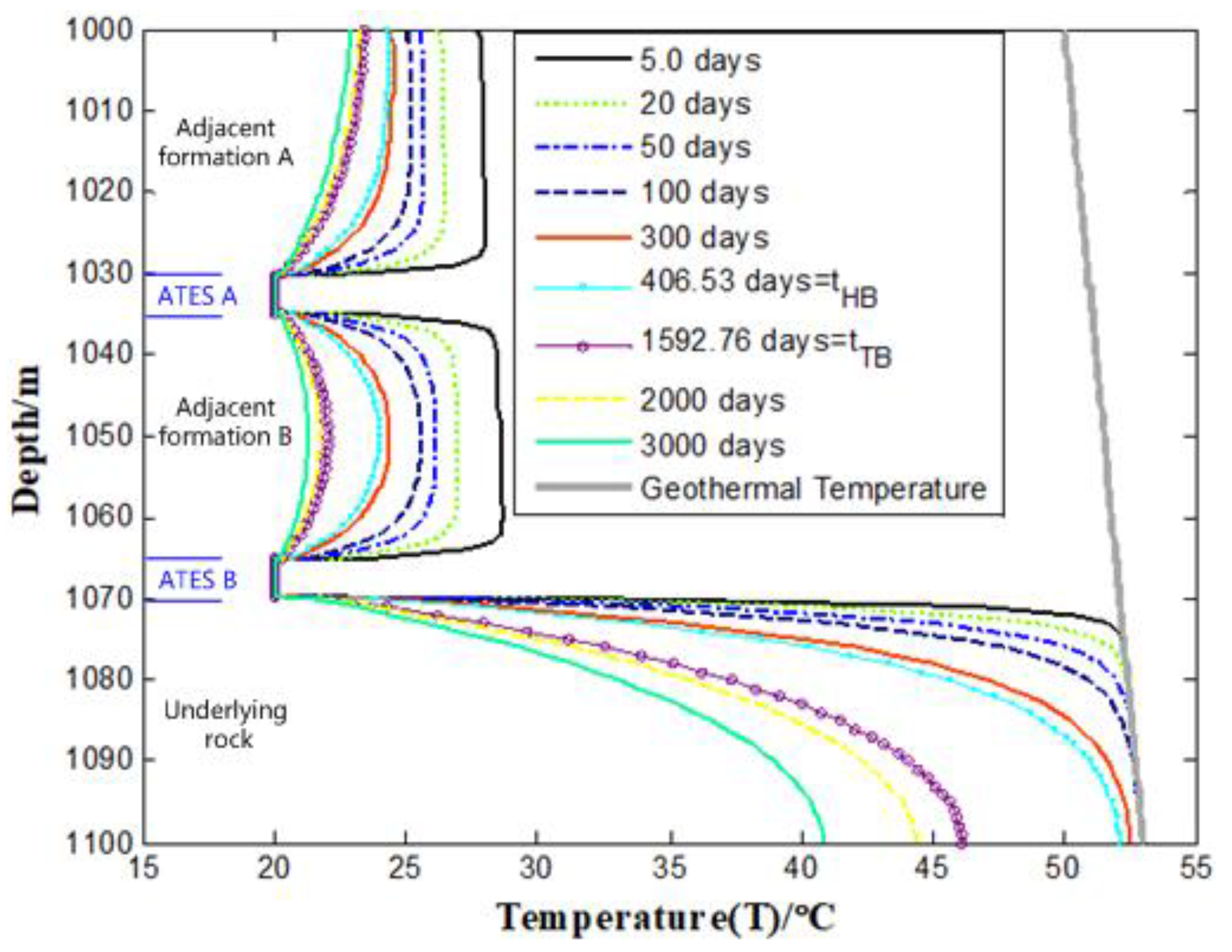
- The tubing fluid in sections of adjacent formations A (1000 m ≤ z ≤ 1030 m) and B (1035 m ≤ z ≤ 1065 m) is continuously cooled by the injected fluid, with heat convection and conduction of wellbore fluid dominating the heat transfer, causing a gradual temperature decrease until it approaches the injected fluid temperature. However, for wellbore fluid in the underlying rock depth range (1070 m ≤ z ≤ 1100 m), longitudinal heat conduction dominates the heat transfer, resulting in a more gradual temperature decrease.
- (2)
- In sections of ATES A (1030 m ≤ z ≤ 1035 m) and B (1065 m ≤ z ≤ 1070 m), the fluid temperature in the tubing is equal to the reinjection temperature (Tin = 20℃) throughout the injection life. As a result, the longitudinal temperature gradient inside the tubing for ATES A and B sections almost always approaches zero. In contrast, the absolute value of the temperature gradient inside the tubing for the depth range of impermeable formations is larger.
- (3)
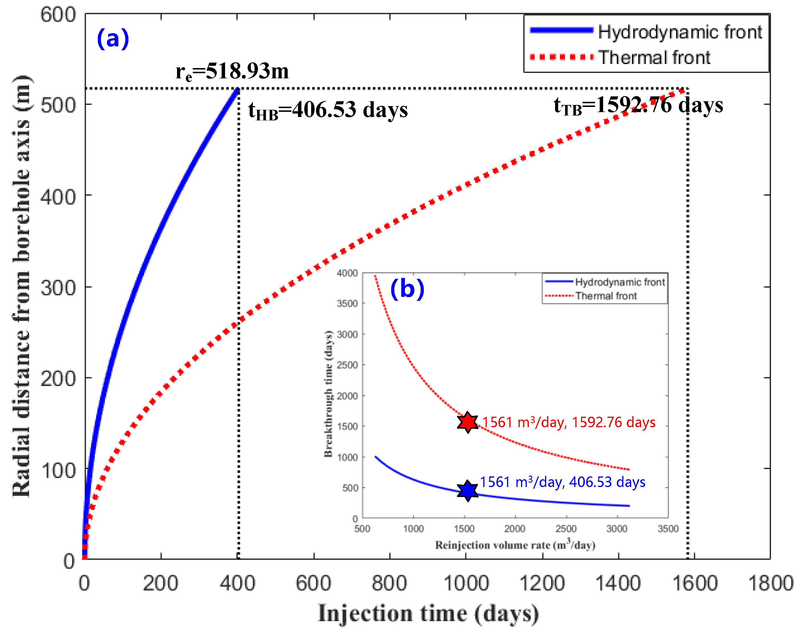
- Before hydrodynamic breakthrough time (tHB = 406.53 days), the tubing temperature changes significantly with reinjection time in sections of adjacent formations A and B, while the temperature changes little in the section of the underlying rock. However, after the thermal breakthrough time (tTB = 1592.76 days), the temperature change inside the tubing for the underlying rock section is more significant than that in adjacent formations A and B.
- (4)
- In the upper part of ATES A (1010–1020 m) and ATES B (1050–1060 m), before the thermal breakthrough, the temperature curve with depth shows a vertical distribution, with the temperature increase rate being almost zero. After the thermal breakthrough, the temperature increase rate is negative. Additionally, for the bottom hole (z = 1100 m), about 40 m away from the bottom of ATES B, the temperature is almost equal to the original formation temperature before the thermal breakthrough, which drops by 13% after the thermal breakthrough. Therefore, the temperature inside the tubing can be effectively used to monitor hydrodynamic or thermal breakthrough occurrences based on these observations.
3.3. Dynamic Thermal Performance Analysis of MATES
3.3.1. Spatial Distribution of the Downhole Transient Temperature (1000 m
- (1)
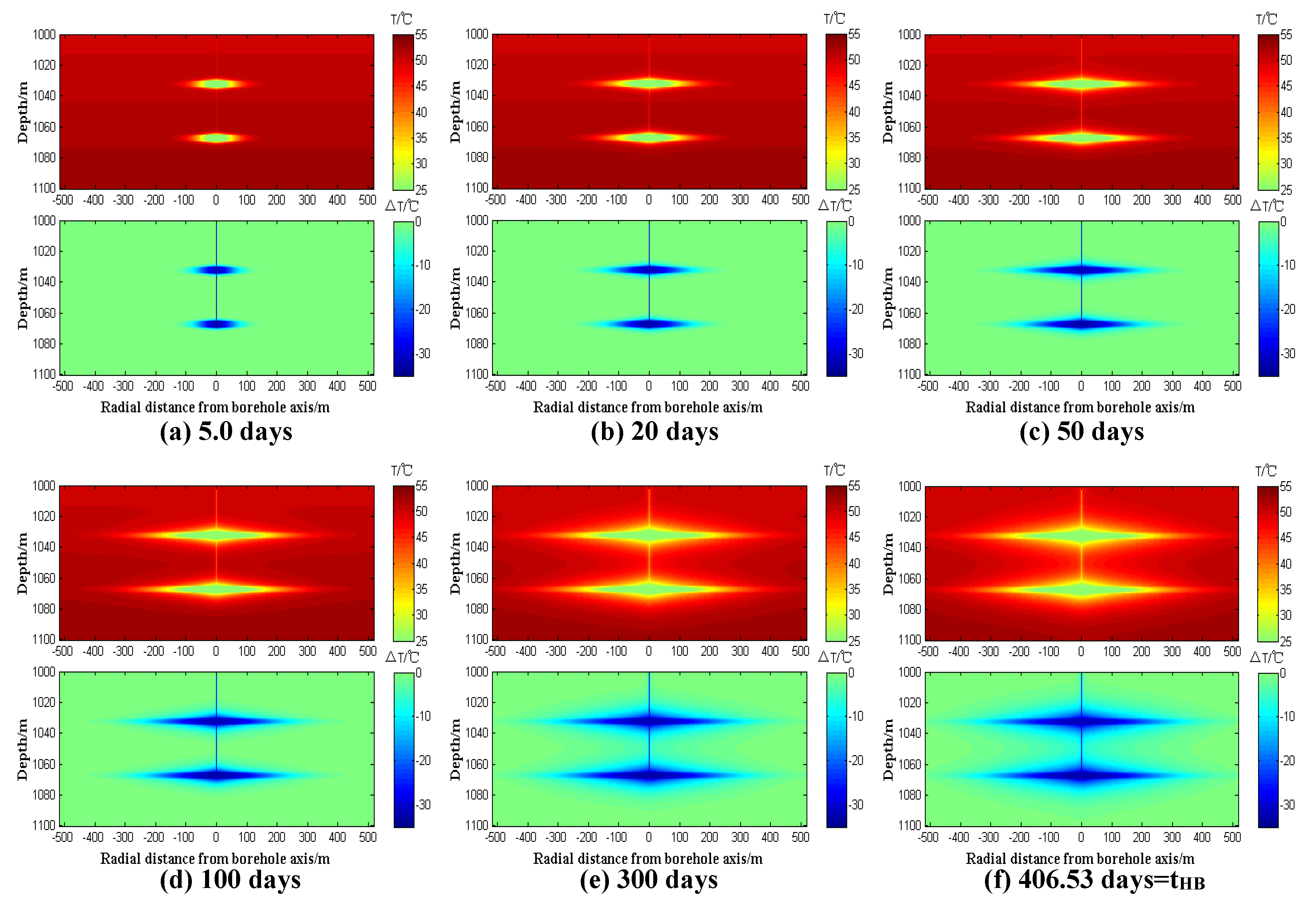
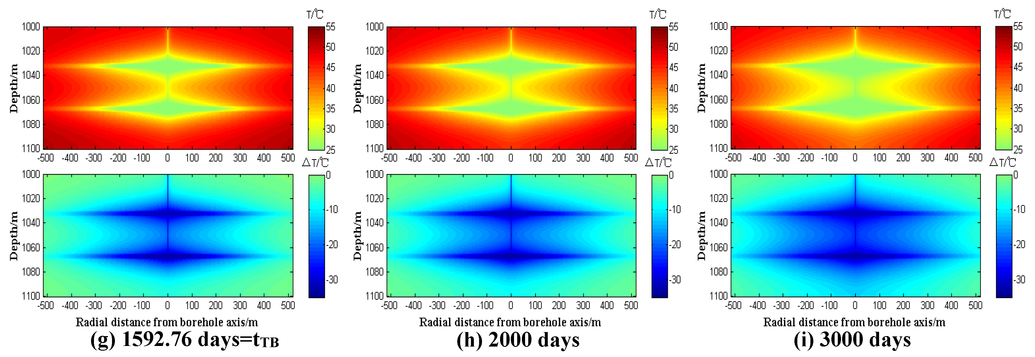
- The temperature profile can easily determine the location of the ATES, as the spatial downhole temperature distribution resembles the shape of a “compass”; this is because the reinjection fluid of the ATES constantly migrates from the wellbore to the thermal reservoir boundary, leading to differences in cooling time for different radial positions of the ATES, resulting in varying temperatures. The temperature of the ATES near the wellbore decreases significantly, while the temperature of the ATES further from the wellbore decreases only slightly.
- (2)
- The ATES and the impermeable formations above and below are continuously cooled by the injected fluid, causing a gradual temperature decrease. As the hydrodynamic front advances, the range of cooled impermeable formations increases gradually. At the later stage of reinjection, the temperature of the ATES (1030 m ≤ z ≤ 1035 m, 1065 m ≤ z ≤ 1070 m) approaches that of the injected fluid. Moreover, Figure 6g–i reveals that during the entire reinjection life, the temperature of the ATES decreases gradually, but not indefinitely, with a “steady state” eventually reached.
- (3)
- When the hydraulic front breaks through (Figure 6f), the temperature of the heat storage boundary (Re = 518 m) does not decrease significantly. However, the boundary temperature drops significantly when the thermal front breaks through. Additionally, the entire thermal reservoir (1030 m ≤ z ≤ 1035 m, 1065 m ≤ z ≤ 1070 m) is wholly cooled for about 3000 days (Figure 6i), about twice the thermal front breakthrough time, after which, the whole heat reservoir temperature is almost equal to that of the injected fluid.
3.3.2. Sensitivity Analysis of ATES Thermal Extraction
3.3.3. Comprehensive Comparison of Sensitivity Analysis
4. Conclusions
- (a)
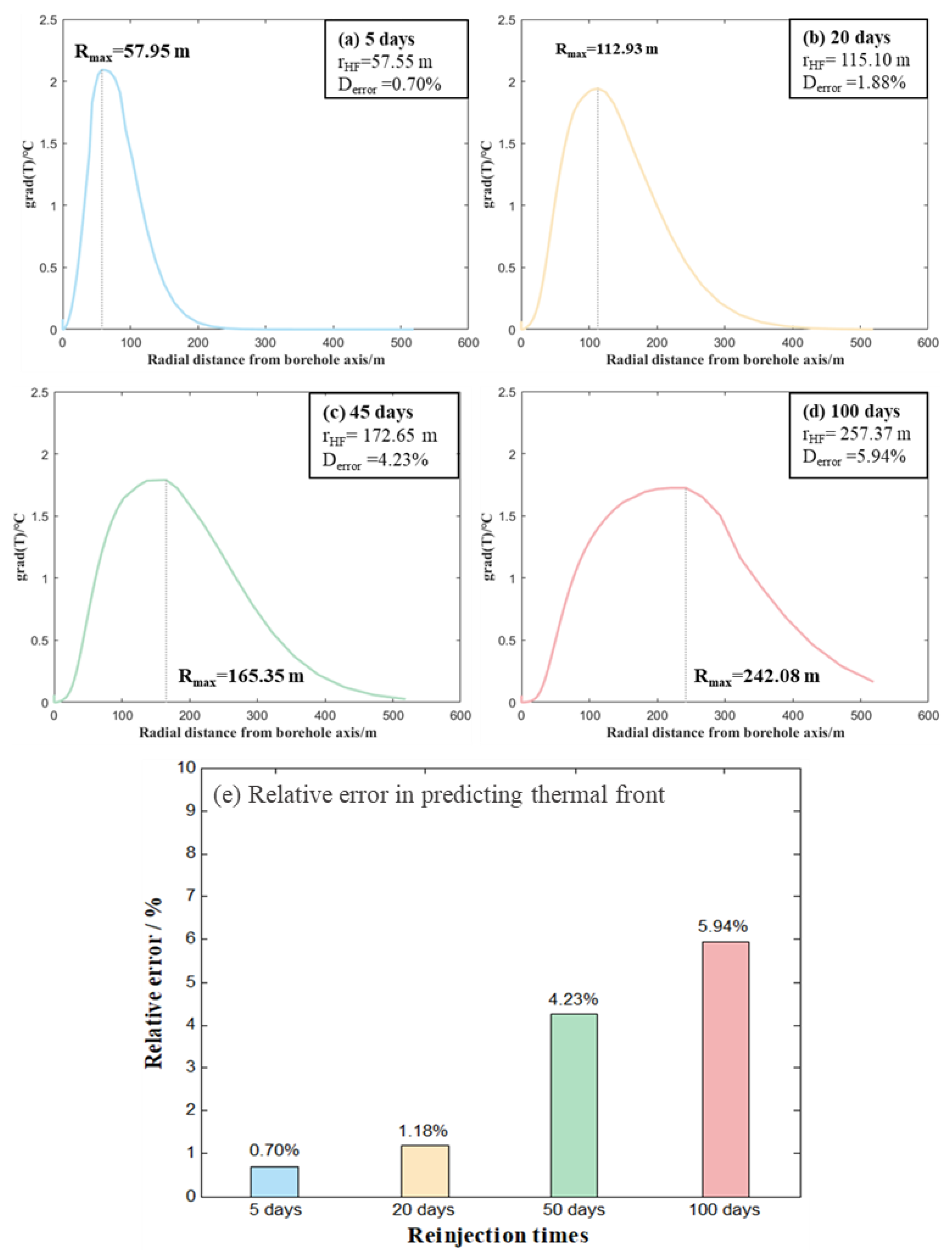
- The accuracy of the thermal front migration calculation model for geothermal reservoirs with radial fluid seepage has been confirmed. The position of the hydraulic front can be used to accurately predict the position of the thermal front before the hydraulic breakthrough, as the radial position (Rmax) of the maximum radial temperature gradient corresponds well with the calculated radial position (rHF) of the thermal front. The relative error between Rmax and rHF ranges from 0.70% to 5.94%, providing a reliable basis for forecasting the thermal front position various times before hydraulic breakthrough.
- (b)
- The temperature increase rate in the upper parts of ATES A (1010–1020 m) and ATES B (1050–1060 m) is almost negligible. However, the temperature increase rate turns negative after the thermal breakthrough (t > tTB = 1592.76 days). Furthermore, the temperature in the bottom hole (z = 1100 m), located approximately 40 m from the base of ATES B, remains close to the formation’s original temperature before the thermal breakthrough. Following the thermal breakthrough, the temperature drops by approximately 13%. These trends can serve as an indicator to detect hydrodynamic or thermal breakthroughs based on temperature monitoring inside the tubing.
- (c)
- The temperature gradient in the ATES section is close to zero (grad(T) = 0). Conversely, the temperature gradient in the impermeable formations section is more significant, allowing for identifying the location of the ATES or impermeable formations through analysis of the temperature inside the tubing.
- (d)
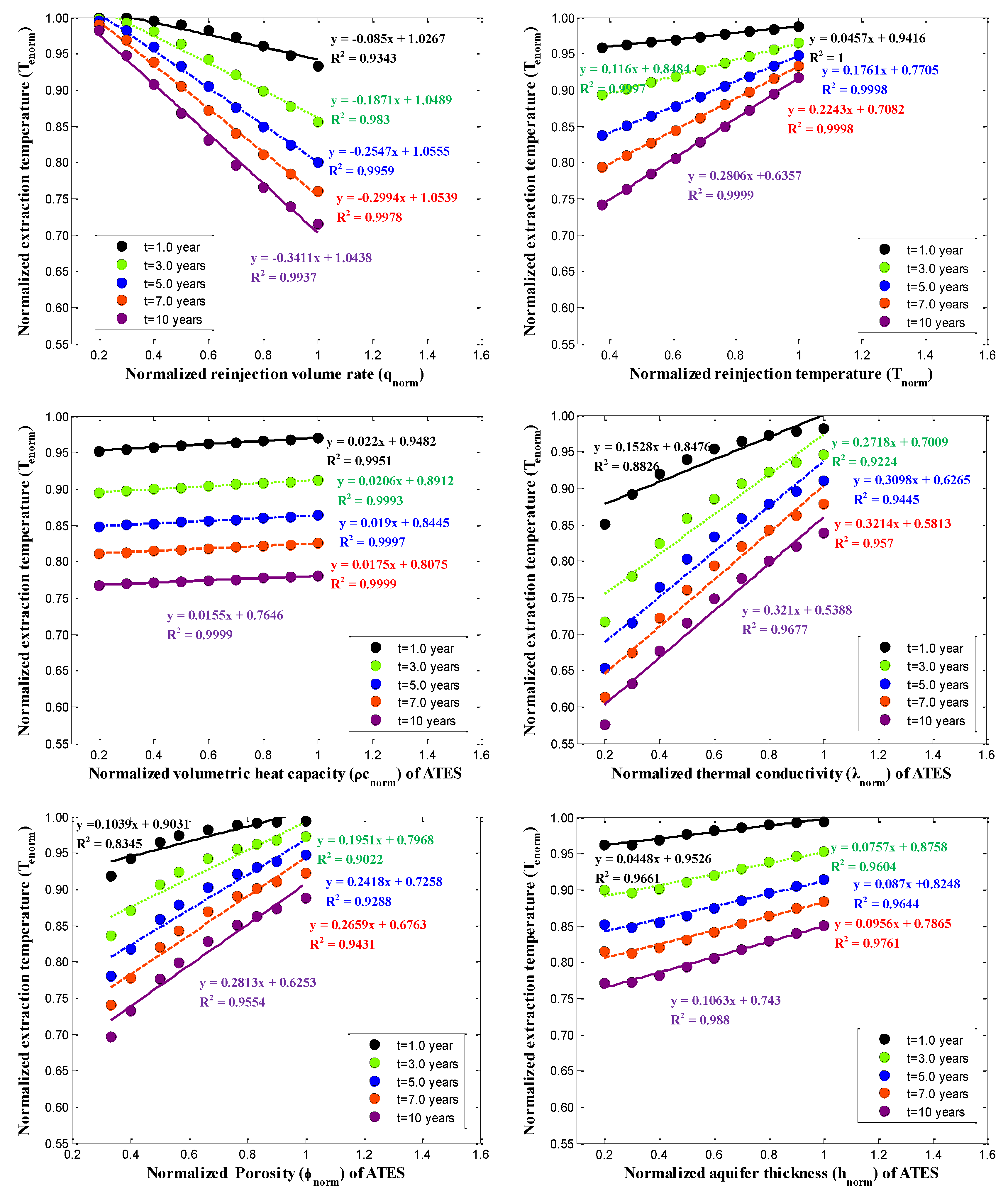
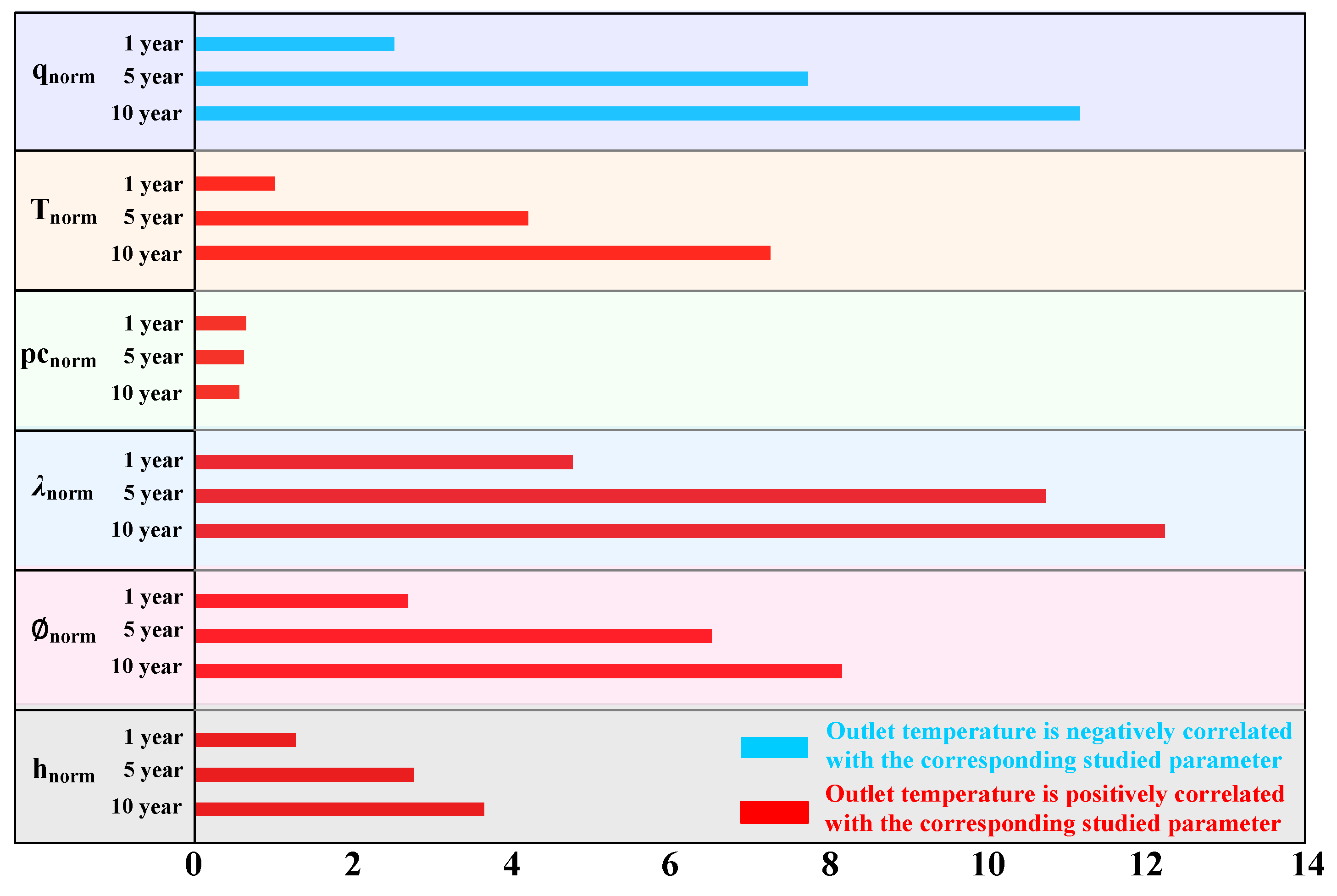
- The sensitivity analysis revealed that the normalized thermal extraction temperature variation with various normalized parameters is nearly linear. Furthermore, the following significant findings can be noted: (i) Among the reservoir factors (such as λm, (ρc)m, ∅m, and hm of the ATES), λm holds the most significant influence on the thermal extraction rate. In contrast, (ρc)m has the weakest impact. In contrast, qin had a significantly higher impact on thermal extraction temperature than Tin, with only qin showing a negative correlation with the thermal extraction temperature. (ii) Thermal conductivity and porosity are vital evaluation indices for assessing thermal reservoir development. Similarly, the reinjection volume rate is critical among the various injection parameters. As the reinjection time increases, the impact of different parameters on heat extraction temperature becomes more significant. Hence, the reinjection time must be meticulously considered in evaluating heat storage or heat extraction.
- (e)
- This study is applicable not only for single ATES but also for MATES, allowing us to consider the aquifer and adjacent formation as having multiple layers with dynamic thermo–physical properties. Moreover, the proposed coupled thermal-hydraulic model, as opposed to analytical or semi-analytical models, offers the capability to predict the complete dynamic temperature distribution within the wellbore of complex configuration and reservoirs under more realistic heat exchange conditions.
- (f)
- To make the model more closely resemble the natural geothermal geological environment, there are two main tasks for the next step: first, considering random fractures’ impact on temperature and the thermal front, and secondly, studying the relationship between transient temperatures at different positions within the wellbore and the fluid front/thermal front.
Author Contributions
Funding
Data Availability Statement
Acknowledgments
Conflicts of Interest
Nomenclature
| cm | Specific heat capacity of the matrix in ATES, J/(kg·K) |
| cs | Specific heat capacity of the impermeable media, J/(kg·K) |
| Cv | Coefficient of variation, %, in Equation (38) |
| cw | Specific heat capacity of water, J/(kg·K) |
| cw(T) | The fitting functions of specific heat capacity of water with different temperatures, Equation (23) |
| gT | The undisturbed geothermal gradient, °C/m |
| Grad(T) | The temperature gradient, °C/m |
| Derror | Relative error between the rHF and Rmax, Derror = |(Rmax-rHF)|/ rHF, dimensionless |
| hm | Aquifer thickness/height, m |
| hnorm | Normalized reservoir thickness, dimensionless |
| hover | The thickness of the overlying, m |
| hunder | The thickness of the underlying, m |
| hc | Convection heat transfer coefficient, W/(m2·K) |
| L | The characteristic length in Equation (16), m |
| H1 | The depth of the bottom of the ATES A, m |
| H2 | The depth of the bottom of the ATES B, m |
| n | The coefficients in Equation (16), n = 0.3 |
| Kslope | The slope of normalized extraction temperature with different normalized values of various parameters, dimensionless |
| PA | The ratio of the volumetric reinjection rate of ATES A to the total volumetric reinjection rate (qin), % |
| Prf | Prandtl number, dimensionless |
| qin | Total volumetric reinjection rate, m3/s |
| qnorm | Normalized total volumetric reinjection rate, dimensionless |
| r | The radial distance from the borehole axis, m |
| rai | Inside radius of cement A, m |
| rci | Inside the radius of the casing, m |
| re | The radial distance from the borehole axis to the reservoir limit, m |
| rHF | The radial position of the hydrodynamic front with different reinjection times, m |
| rTF | The radial position of the thermal front with different reinjection times, m |
| rti | Inside radius of the tubing, m |
| rto | Outside radius of the tubing, m |
| rwb | Outside radius of the wellbore, m |
| rab | Outside radius of the cement A, m |
| rbb | Outside radius of the cement B, m |
| rcb | Outside radius of the cement C, m |
| Ref | Reynolds number, dimensionless |
| r(i) | The radial distance from discrete nodes to borehole axis, m |
| Rmax | Radial position (Rmax) of the maximum temperature gradient of ATES, m |
| R2 | Multiple correlation coefficient, dimensionless |
| s | The standard deviation of the sample data, in Equation (39) |
| t | Reinjection time, day |
| tHB | The time of hydrodynamic breakthrough, Equation (25) |
| tTB | The time of thermal breakthrough, Equation (26) |
| T | The temperature at a specific reinjection time, °C |
| Ta | Initial ambient temperature, °C |
| Te | Thermal extraction temperature, °C |
| Tenorm | Normalized thermal extraction temperature, dimensionless |
| Tsur | Initial surface temperature, °C |
| Tbm | The temperature of aquifers at interfaces between the aquifers and the adjacent formations, °C |
| Tbs | The temperature of adjacent formations at interfaces between the aquifers and the adjacent formations, °C |
| Tbf | The fluid temperature at the tubing/tubing wall interface, °C |
| Tbw | Tubing wall temperature at the tubing/tubing wall interface, °C |
| Ttw | Tubing fluid temperature at the interface between the tubing and the ATES, °C |
| Ttm | The temperature of the ATES at the interface between the tubing and the ATES, °C |
| Tin | Reinjection temperature/°C |
| Tnorm | Normalized reinjection temperature, dimensionless |
| vwr(r) | Radial seepage velocity of the fluid in ATES, m/s. Equation (10) |
| vz | Downward seepage velocity of the tubing fluid, m/s. Equation (2) |
| x | The radial distance from the borehole axis in the Cartesian coordinate system, m |
| yi | A data sample |
| Average of sample data | |
| z | Vertical depth from surface, m |
| zb | The depth of boundaries between the aquifers and the adjacent formations, m |
| zmax | Total well depth from surface, m |
| λw | Thermal conductivity of the water, W/(m·K) |
| λw(T) | The fitting functions of thermal conductivity of water with different temperatures, Equation (24) |
| λm | Thermal conductivity of the aquifers, W/(m·K) |
| Equivalent thermal conductivity of the aquifers, W/(m·K) | |
| λnorm | Normalized thermal conductivity of the aquifers, dimensionless |
| λs | Thermal conductivity of impermeable media, W/(m·K) |
| Equivalent thermal conductivity of impermeable media, W/(m·K) | |
| ρw | The density of water, kg/m3 |
| ρw(T) | The fitting functions of the density of water with different temperatures, Equation (22) |
| ρm | The density of matrix in ATES, kg/m3 |
| ρs | The density of impermeable media, kg/m3 |
| Equivalent volumetric heat capacity of impermeable media, J/(m3·K) | |
| Equivalent volumetric heat capacity of aquifers, J/(m3·K) | |
| (ρc)m | Volumetric heat capacity of ATES, J/(m3·K) |
| ρcnorm | Normalized volumetric heat capacity of ATES, dimensionless |
| ∅ | Porosity, dimensionless |
| ∅m | The porosity of ATES, dimensionless |
| ∅norm | Normalized porosity, dimensionless |
| ΔT | ΔT = T − T0, where T means the temperature at a specific reinjection time and T0 is the initial (undisturbed) geothermal temperature, °C |
| ∆t | The discrete time, day |
| ∆x | The discrete radial spacing, m |
| ∆z | The discrete longitudinal spacing, m |
Appendix A. Implicit Finite Difference Discrete Schemes of the Mathematics Model
- (1)
- The heat-transfer finite difference equation in the tubing can be written as:
- (2)
- The transient temperature field finite difference equation for the tubing wall, tubing–casing annulus, casing, cement, overburden, and adjacent formations can be given by:
- (3)
- We can express the temperature field finite difference equation of the MATES as:

Appendix B. Thermo–Physical Properties of Water with Different Temperatures

Appendix C. Data Sets Used in This Study
| Properties | Value |
|---|---|
| Outside radius of wellbore (rwb)/m | 0.09 |
| Reservoir limit (re)/m | 184.36 |
| Thickness of overlying (hover)/m | 30 |
| Thickness of aquifer (hm)/m | 10 |
| Thickness of underlying (hunder)/m | 60 |
| Total volumetric Reinjection rate (qin)/ m3/d | 271.43 |
| Reinjection temperature (Tin)/ °C | 20 |
| Surface temperature (Tsur)/°C | 20 |
| Geothermal gradient (gT)/°C/m | 0.03 |
| Material | Overlying Rock | Underlying Rock | Matrix of the Aquifer | |
|---|---|---|---|---|
| Properties | ||||
| Density/kg/m3 | 2450 | 2650 | 2550 | |
| Specific heat/[J/(Kg·°C)] | 950 | 820 | 850 | |
| Thermal conductivity coefficient/[W/(m·°C)] | 2.1 | 2.2 | 2.5 | |
| Porosity/% | - | - | 15 | |
| Radial Direction | |
| Inside radius of tubing (rti)/m | 0.050 |
| Outside radius of tubing (rto)/m | 0.055 |
| Inside radius of casing (rci)/m | 0.065 |
| Inside radius of cement A (rai)/m | 0.070 |
| Outside radius of cement A (rab)/m | 0.090 |
| Outside radius of cement B (rbb)/m | 0.110 |
| Outside radius of cement C (rcb)/m | 0.130 |
| Reservoir limit (re)/m | 518.92 |
| Longitudinal direction | |
| Interval of cement A/m | 0–1030 |
| Interval of cement B/m | 0–1000 |
| Interval of cement C/m | 0–500 |
| Interval of caprock/m | 0–1000 |
| Interval of adjacent formation A/ m | 1000–1030 |
| Interval of ATES A/ m | 1030–1035 |
| Interval of adjacent formation B/ m | 1035–1065 |
| Interval of ATES B/ m | 1065–1070 |
| Interval of underlying rock/ m | 1070–1100 |
| Material | Tubing (Casing) | Cements | Caprock | Adjacent Formations and Underlying Rock | |
|---|---|---|---|---|---|
| Properties | |||||
| Density/kg/m3 | 7900 | 2150 | 1920 | 2500 | |
| Specific heat/[J/(Kg·°C)] | 460 | 2000 | 922 | 900 | |
| Thermal conductivity coefficient/[W/(m·°C)] | 16.2 | 0.7 | 1.02 | 2.2 | |
| Ambient temperature | |
| Surface temperature (Tsur)/°C | 20 |
| Geothermal gradient (gT)/°C/m | 0.03 |
| Reinjection conditions | |
| Total volumetric Reinjection rate (qin) /m3/d | 3121.48 |
| Volumetric Reinjection rate of ATES A/m3/d | 1560.74 |
| Volumetric Reinjection rate of ATES B/m3/d | 1560.74 |
| Reinjection temperature/°C | 20 |
References
- Lee, K.S. Effects of regional groundwater flow on the performance of an aquifer thermal energy storage system under continuous operation. Hydrogeol. J. 2014, 22, 251–262. [Google Scholar] [CrossRef]
- Shi, Y.; Song, X.; Li, J.; Wang, G.; Zheng, R.; YuLong, F. Numerical investigation on heat extraction performance of a multilateral-well enhanced geothermal system with a discrete fracture network. Fuel 2019, 244, 207–226. [Google Scholar] [CrossRef]
- Xu, J.; Wang, R.; Li, Y. A review of available technologies for seasonal thermal energy storage. Sol. Energy 2014, 103, 610–638. [Google Scholar] [CrossRef]
- Zhou, X.; Gao, Q.; Chen, X.; Yan, Y.; Spitler, J.D. Developmental status and challenges of GWHP and ATES in China. Renew. Sustain. Energy Rev. 2015, 42, 973–985. [Google Scholar] [CrossRef]
- Hill, M.; DeHouche, Z. A comparative analysis of the effectiveness of aquifer thermal energy storage in Expeditionary Campaign Infrastructure. Appl. Therm. Eng. 2017, 114, 271–278. [Google Scholar] [CrossRef]
- Abbasi, M.; Khazali, N.; Sharifi, M. Analytical model for convection-conduction heat transfer during water injection in fractured geothermal reservoirs with variable rock matrix block size. Geothermics 2017, 69, 1–14. [Google Scholar] [CrossRef]
- Aliyu, M.D.; Chen, H.-P. Optimum control parameters and long-term productivity of geothermal reservoirs using coupled thermo-hydraulic process modelling. Renew. Energy 2017, 112, 151–165. [Google Scholar] [CrossRef]
- Huang, G.; Ma, H.; Hu, X.; Cai, J.; Li, J.; Luo, H.; Pan, H. A Coupled Model of Two-Phase Fluid Flow and Heat Transfer to Transient Temperature Distribution and Seepage Characteristics for Water-Flooding Production Well with Multiple Pay Zones. Energies 2019, 12, 1854. [Google Scholar] [CrossRef]
- Ferreira, M.V.; Hafemann, T.E.; Barbosa Jr, J.R.; da Silva, A.K.; Hasan, R. A numerical study on the thermal behavior of wellbores. SPE Prod. Oper. 2017, 32, 564–574. [Google Scholar] [CrossRef]
- Lauwerier, H. The transport of heat in an oil layer caused by the injection of hot fluid. Appl. Sci. Res. Sect. A 1955, 5, 145–150. [Google Scholar] [CrossRef]
- Sauty, J.; Gringarten, A.; Menjoz, A.; Landel, P. Sensible energy storage in aquifers: 1. Theoretical study. Water Resour. Res. 1982, 18, 245–252. [Google Scholar]
- Gringarten, A.C.; Sauty, J. A theoretical study of heat extraction from aquifers with uniform regional flow. J. Geophys. Res. 1975, 80, 4956–4962. [Google Scholar] [CrossRef]
- Ezekoye, O.A. Conduction of Heat in Solids. In SFPE Handbook of Fire Protection Engineering; Springer: Berlin/Heidelberg, Germany, 2016; pp. 25–52. [Google Scholar]
- Chen, C.S.; Reddell, D.L. Temperature distribution around a well during thermal injection and a graphical technique for evaluating aquifer thermal properties. Water Resour. Res. 1983, 19, 351–363. [Google Scholar]
- Molson, J.W.; Frind, E.O.; Palmer, C.D. Thermal energy storage in an unconfined aquifer: 2. Model development, validation, and application. Water Resour. Res. 1992, 28, 2857–2867. [Google Scholar]
- Mongelli, F.; Pagliarulo, P. Influence of water recharge on heat transfer in a semi-infinite aquifer. Geothermics 1997, 26, 365–378. [Google Scholar]
- Cheng, A.D.; Ghassemi, A.; Detournay, E. Integral equation solution of heat extraction from a fracture in hot dry rock. Int. J. Numer. Anal. Methods Geomech. 2001, 25, 1327–1338. [Google Scholar]
- Boyadjiev, L.; Kamenov, O.; Kalla, S. On the Lauwerier formulation of the temperature field problem in oil strata. Int. J. Math. Math. Sci. 2005, 2005, 1577–1588. [Google Scholar]
- Shaw-Yang, Y.; Hund-Der, Y. An analytical solution for modeling thermal energy transfer in a confined aquifer system. Hydrogeol. J. 2008, 16, 1507. [Google Scholar]
- Li, K.Y.; Yang, S.Y.; Yeh, H.D. An analytical solution for describing the transient temperature distribution in an aquifer thermal energy storage system. Hydrol. Process. 2010, 24, 3676–3688. [Google Scholar]
- Yang, S.-Y.; Yeh, H.-D.; Li, K.-Y. Modelling transient temperature distribution for injecting hot water through a well to an aquifer thermal energy storage system. Geophys. J. Int. 2010, 183, 237–251. [Google Scholar]
- Yeh, H.D.; Yang, S.Y.; Li, K.Y. Heat extraction from aquifer geothermal systems. Int. J. Numer. Anal. Methods Geomech. 2012, 36, 85–99. [Google Scholar]
- Ganguly, S. Exact solution of heat transport equation for a heterogeneous geothermal reservoir. Energies 2018, 11, 2935. [Google Scholar]
- Fischer, T.; Walther, M.; Sattler, S.; Naumov, D.; Kolditz, O. GO2OGS: A versatile workflow to integrate complex geological information with fault data into numerical simulation models. Geosci. Model Dev. Discuss. 2015, 8, 6309–6348. [Google Scholar]
- Wong, Z.Y.; Horne, R.; Voskov, D. Comparison of nonlinear formulations for geothermal reservoir simulations. In Proceedings of the 41st Workshop on Geothermal Reservoir Engineering, Stanford, CA, USA, 22–24 February 2016. [Google Scholar]
- Xia, Y.; Plummer, M.; Podgorney, R.; Ghassemi, A. An Assessment of Some Design Constraints on Heat Production of a 3D Conceptual EGS Model Using an Open-Source Geothermal Reservoir Simulation Code; Idaho National Lab.(INL): Idaho Falls, ID, USA, 2016. [Google Scholar]
- Shook, G.M. Predicting thermal breakthrough in heterogeneous media from tracer tests. Geothermics 2001, 30, 573–589. [Google Scholar]
- Bodvarsson, G. Thermal problems in the siting of reinjection wells. Geothermics 1972, 1, 63–66. [Google Scholar] [CrossRef]
- Molz, F.J.; Warman, J.C.; Jones, T.E. Aquifer storage of heated water: Part I—A field experiment. Groundwater 1978, 16, 234–241. [Google Scholar]
- Molz, F.; Parr, A.D.; Andersen, P.; Lucido, V.; Warman, J. Thermal energy storage in a confined aquifer: Experimental results. Water Resour. Res. 1979, 15, 1509–1514. [Google Scholar]
- Tsang, C.F.; Buscheck, T.; Doughty, C. Aquifer thermal energy storage: A numerical simulation of Auburn University field experiments. Water Resour. Res. 1981, 17, 647–658. [Google Scholar]
- Lippmann, M.; Bodvarsson, G.; Witherspoon, P. Preliminary simulation studies related to the Cerro Prieto field. Geothermics 1980, 9, 197–207. [Google Scholar] [CrossRef]
- Satman, A. Solutions of Heat-and Fluid-Flow Problems in Naturally Fractured Reservoirs: Part 1–Heat-Flow Problems. SPE Prod. Eng. 1988, 3, 463–466. [Google Scholar]
- Vinsome, P.; Shook, G. Multi-purpose simulation. J. Pet. Sci. Eng. 1993, 9, 29–38. [Google Scholar] [CrossRef]
- Hayba, D.O.; Ingebritsen, S. The Computer Model HYDROTHERM, a Three-Dimensional Finite-Difference Model to Simulate Ground-Water Flow and Heat Transport in the Temperature Range of 0 to 1200 Degrees C; US Geological Survey; USGS Earth Science Information Center: Denver, CO, USA, 1994. [Google Scholar]
- Pruess, K. The TOUGH codes—A family of simulation tools for multiphase flow and transport processes in permeable media. Vadose Zone J. 2004, 3, 738–746. [Google Scholar]
- Stopa, J.; Wojnarowski, P. Analytical model of cold water front movement in a geothermal reservoir. Geothermics 2006, 35, 59–69. [Google Scholar] [CrossRef]
- Ascencio, F.; Samaniego, F.; Rivera, J. A heat loss analytical model for the thermal front displacement in naturally fractured reservoirs. Geothermics 2014, 50, 112–121. [Google Scholar] [CrossRef]
- Abbasi, M.; Mansouri, M.; Daryasafar, A.; Sharifi, M. Analytical model for heat transfer between vertical fractures in fractured geothermal reservoirs during water injection. Renew. Energy 2019, 130, 73–86. [Google Scholar] [CrossRef]
- Mahmoodpour, S.; Singh, M.; Turan, A.; Bär, K.; Sass, I. Simulations and global sensitivity analysis of the thermo-hydraulic-mechanical processes in a fractured geothermal reservoir. Energy 2022, 247, 123511. [Google Scholar] [CrossRef]
- Mahmoodpour, S.; Singh, M.; Bär, K.; Sass, I. Thermo-hydro-mechanical modeling of an enhanced geothermal system in a fractured reservoir using carbon dioxide as heat transmission fluid-A sensitivity investigation. Energy 2022, 254, 124266. [Google Scholar] [CrossRef]
- Huang, G.; Hu, X.; Ma, H.; Liu, L.; Yang, J.; Zhou, W.; Liao, W.; Ningbo, B. Optimized geothermal energy extraction from hot dry rocks using a horizontal well with different exploitation schemes. Geotherm. Energy 2023, 11, 5. [Google Scholar] [CrossRef]
- Abdi, H. Coefficient of variation. Encycl. Res. Des. 2010, 1, 169–171. [Google Scholar] [CrossRef]
- McAuliffe, R.E. Coefficient of variation. Wiley Encycl. Manag. 2015, 8, 39. [Google Scholar] [CrossRef]
- Wagner, W.; Pruß, A. IAPWS Formul. 1995 for the thermodynamic properties of ordinary water substance for general and scientific use. J. Phys. Chem. Ref. Data 2002, 31, 387–535. [Google Scholar] [CrossRef]
- Zhang, M.; Che, Z.; Chen, J.; Zhao, H.; Yang, L.; Zhong, Z.; Lu, J. Experimental determination of thermal conductivity of water− agar gel at different concentrations and temperatures. J. Chem. Eng. Data 2011, 56, 859–864. [Google Scholar] [CrossRef]

Disclaimer/Publisher’s Note: The statements, opinions and data contained in all publications are solely those of the individual author(s) and contributor(s) and not of MDPI and/or the editor(s). MDPI and/or the editor(s) disclaim responsibility for any injury to people or property resulting from any ideas, methods, instructions or products referred to in the content. |
© 2023 by the authors. Licensee MDPI, Basel, Switzerland. This article is an open access article distributed under the terms and conditions of the Creative Commons Attribution (CC BY) license (https://creativecommons.org/licenses/by/4.0/).
Share and Cite
Huang, G.; Liu, L.; Mu, M.; Yang, J.; Ding, H. Prediction of Dynamic Temperature and Thermal Front in a Multi-Aquifer Thermal Energy Storage System with Reinjection. Energies 2023, 16, 7358. https://doi.org/10.3390/en16217358
Huang G, Liu L, Mu M, Yang J, Ding H. Prediction of Dynamic Temperature and Thermal Front in a Multi-Aquifer Thermal Energy Storage System with Reinjection. Energies. 2023; 16(21):7358. https://doi.org/10.3390/en16217358
Chicago/Turabian StyleHuang, Guoshu, Liang Liu, Mangen Mu, Jian Yang, and Hui Ding. 2023. "Prediction of Dynamic Temperature and Thermal Front in a Multi-Aquifer Thermal Energy Storage System with Reinjection" Energies 16, no. 21: 7358. https://doi.org/10.3390/en16217358
APA StyleHuang, G., Liu, L., Mu, M., Yang, J., & Ding, H. (2023). Prediction of Dynamic Temperature and Thermal Front in a Multi-Aquifer Thermal Energy Storage System with Reinjection. Energies, 16(21), 7358. https://doi.org/10.3390/en16217358


