Article

Mechanisms and Operational Strategies of Multi-Lateral Steam-Assisted Gravity Drainage (SAGD) for Heterogeneous Reservoirs

1
Research Institute of Exploration and Development, Xinjiang Oilfield Company, PetroChina, Karamay 834000, China
2
Research Institute of Petroleum Exploration & Development, PetroChina, Beijing 100083, China
*
Author to whom correspondence should be addressed.
Energies 2023, 16(21), 7351; https://doi.org/10.3390/en16217351
Submission received: 23 August 2023 / Revised: 18 September 2023 / Accepted: 23 October 2023 / Published: 31 October 2023
(This article belongs to the Section H1: Petroleum Engineering)

Abstract

:
As the SAGD steam chamber and production performance in heavy oil reservoirs under fluvial sedimentation environment are heavily impacted by reservoir heterogeneity, an innovative strategy was proposed in this study coupling rock dilation and multi-lateral wells in SAGD projects to break the mud barriers and achieve uniform steam chamber growth. True tri-axial experiments and numerical simulation were designed to validate the feasibility of this strategy, based on which the branches of the SAGD well pairs were designed and the operational parameters were optimized for different geologic heterogeneity conditions. The tri-axial experiment results indicate that the rock formations in the heavy oil reservoirs of the F oilfield exhibit significant shear dilation effects under low confinement pressure conditions, with a volumetric dilation capacity of up to 7%. The branches should be deployed in an interleaved manner, with a horizontal displacement of 20 m and a vertical displacement of 6 m. The optimal results are achieved when the branches intersect the interbeds, allowing for enhanced steam chamber conformance and enlarged volume. Dilation zones of 3–8 m can be created above the steam-injection horizontal wells and around the branches in the reservoir during the dilation of SAGD steam chambers. The maximum volume of dilation fluid used for hydraulic dilation is suggested to be less than 2000 m3. This strategy has been validated as being successful in the pilot SAGD well pair in the F oilfield, China, with the SAGD preheating time reduced by 50% and an incremental oil rate of 4.5 tones/day, indicating encouraging potentials in similar heavy oil reservoirs.

1. Introduction

Steam-Assisted Gravity Drainage, invented by Roger Butler and his colleagues in Imperial Oil in the late 1970s [1], is one of the most effective recovery methods for heavy oil and bitumen deposits. As most of the well pair configuration is the parallel dual well horizontal well deployment with a horizontal segment of 400 m or even longer, the reservoir heterogeneity is sensitive to the steam conformance and SAGD production performance.
As the difference in sedimentation environment, which is manifested in variations of lithology or petrophysical properties like permeability, the heterogeneity-induced uneven steam chamber development is a conventional phenomenon in the SAGD recovery process, and directly impacts the oil rate and recovery factor.
The understanding of the shale barrier configuration is the prerequisite to make strategies to control or break it [2,3]. Researchers have made investigations including fast screening of 3D heterogeneous shale barrier configurations [4], data-driven models for characterizing shale barrier configuration [5], numerical studies of the effects of lean zones and evolution characteristics of the SAGD steam chamber [6], application of cluster analysis and artificial neural networks [7], and data analytics and machine learning to characterize shale barrier configuration [8]. They have carried out a 3D physical simulation on dual horizontal well SAGD in heterogeneous reservoirs [9], classified the impact of thermal and permeability heterogeneity on SAGD performance [10], and proposed methods to control reservoir heterogeneity [11].
Among various strategies targeting the enhancement of production performance in heterogeneous SAGD projects, the expanding-solvent SAGD (ES-SAGD) method is one of the few methods that reach commercialization. Govind, P. A. proposed that the ES-SAGD can be used in heterogeneous reservoirs to increase the oil rate by solvent-assisted gravity drainage [12]. Venkatramani, A. V. has carried out a mechanistic simulation study of expanding-solvent steam-assisted gravity drainage under reservoir heterogeneity and illustrated its mechanisms [13]. The feasibility of adding solvent into steam has also been validated. Based on these studies, the suitable reservoir condition was investigated [14,15], and the impact of shale barriers on SAGD performance and the hybrid optimization techniques were used to design the solvent-assisted SAGD process [16,17]. Although exponentially reducing the oil viscosity, the solvent is less effective in diffusing into shale barriers and speeds up the steam chamber evolution.
The flow control device (FCD) is particularly effective in dealing with the permeability variations in the wellbore vicinity. By using the carefully designed valve along the horizontal section according to the temperature variation and steam chamber surveillance results, it forces the steam flows into the steam bypassed region. Researchers have carried out evaluation, completion design, implementation, and operations of FCD in SAGD projects [18,19,20], and have studied its potential in SAGD applications [21,22]. Based on its field performance, the future solution by FCD has also been investigated [23]. However, this mechanical method is less effective in dealing with heterogeneities far from the wellbore.
Although controlling wellbore flow using an FCD is effective, the porous flow in the neighboring well pair region is difficult to modify using conventional or wellbore mechanical methods. Fast-SAGD was proposed in this background, which normally requires the drilling of a wedge well or several vertical wells along horizontal sections to force the development of a steam chamber [24]. The feasibility of the Fast-SAGD process in naturally fractured heavy oil reservoirs has been evaluated [25,26], the discrete variables and repetition inhibitory algorithm were utilized to optimize the Fast-SAGD process [27], and a comparative numerical simulation was carried out to compare the production performance of Fast-SAGD and SAGD [28,29]. For SAGD projects with harsh surface conditions or strict environment policies, the infill drilling is not only officially disadvantaged but also requires more sophisticated surface networks.
Based on a review of different SAGD steam chamber improvement methods, the multi-lateral SAGD coupled with an inter-wellbore dilation strategy is proposed in this study, which takes the heterogeneous SAGD deposits in the F oilfield of Xinjiang province, China, as the study area. Unconventional wellbore trajectories and multi-lateral configurations are now widely adopted in oil and gas field development. These techniques effectively enhance recovery efficiency by increasing the oil drainage area in thermal and cold heavy oil production. However, their application in SAGD development for ultra-heavy oil remains unreported.
In 2014, a field trial of multi-lateral SAGD wells was conducted in the F oilfield, which indicated that the branches effectively delivered steam and heated the surrounding crude oil during the initial production phase. However, its mechanism coupling formation and dilation has not yet been fully understood, and the key operational strategies and parameters of this hybrid process need to be optimized.
The authors designed and conducted scaled physical experiments on SAGD reservoir dilation and built numerical simulation models characterizing rock mechanics to illustrate the mechanisms of multi-lateral SAGD dilation in this study. The operational strategies and crucial parameters for the multi-lateral SAGD process were optimized synthetically, which has critical significance in improving steam conformance in similar heavy oil reservoirs.

2. Geologic and Recovery Backgrounds of the Heterogeneous Reservoir

The F oilfield in Xinjiang exhibits fluvial deposition in a continental environment. Its structure comprises south-dipping monoclines that have been segmented by faults, displaying a dip angle ranging from 5° to 10°. The oil sands in this field consist of particles smaller than 300 μm, with minimal contact points or faces due to the presence of bitumen cement. The sand particles have angular shapes with well-defined grain edges, and some are encapsulated in bitumen. The thickness of the oil reservoir in the F oilfield varies from 0.5 to 32 m, exhibiting extensive lateral distribution but poor vertical continuity. The reservoir has a porosity ranging from 25% to 33% and a permeability ranging from 0.7D to 2.7D. Oil saturation levels range from 50% to 75%. Buried at depths of 170 m to 700 m, the formation temperature ranges from 15 to 25 °C. The crude oil’s viscosity at 50 °C ranges from 0.2 × 10⁴ to 1.15 × 10⁶ mPa.s. In particular, the reservoir displays significant heterogeneity (Figure 1), with the permeability variation coefficient ranging from 0.7 to 0.9. The oil-bearing formation exhibits discontinuous lithology with extensive mud barriers ranging from 0.6 m to 2.6 m in thickness. The interbeds extend between 47 m and 200 m laterally. The reservoir rock has an elastic modulus of 310 MPa and a Poisson’s ratio of 0.08. The angle of internal friction measures 35.39°, and the cohesive strength is 0.94 kPa. Additionally, the reservoir has a thermal dilation coefficient of 2.5 × 10⁻⁵/°C.
Following the pilot SAGD test in the Xinjiang F oilfield in 2008, more than 260 SAGD well pairs have been successfully deployed for production. This achievement has led to the commercialized development of this super-heavy oil deposit with an annual output above one million tons. However, as the development progresses, the production performance and steam chamber development were increasingly impacted by the reservoir heterogeneity. Therefore, innovative technologies are needed for the efficient development of this strongly heterogeneous super-heavy oil reservoir to achieve more uniform steam chamber evolution and higher oil recovery factor.
To this end, the strategy of reservoir dilation coupled with multi-lateral SAGD was proposed in this study. The mechanisms, multi-lateral well configurations, and operational parameters are investigated and optimized synthetically.

3. Mechanisms of Reservoir Dilation Coupled with Multi-Lateral SAGD

Compared to conventional SAGD production methods, the branches in multi-lateral SAGD wells serve the purpose of conveying steam and heating the surrounding crude oil. In the absence of an intervening layer or when the intervening layer has limited extent, the surrounding crude oil can bypass the interbed and drain downward, thereby accelerating the expansion of the steam chamber and accessing the crude oil above the interbed at an earlier stage. However, when the branches penetrate a widely distributed interbed, it becomes challenging to establish effective pathways for oil drainage around the branches, thereby limiting their effectiveness (Figure 2).

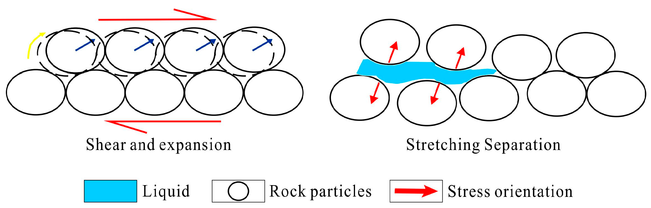
3.1. Mechanisms of Reservoir Dilation

Reservoir dilation denotes the deformation of rocks due to external loading, induced by heightened shear stress or pore pressure. This dilation can enhance porosity and promote improved permeability.
In Xinjiang, ultra-heavy oil sand particles have gradually formed weakly consolidated sandstone with an interconnected structure over an extensive geological timeframe. Following compaction, the sandstone particles predominantly exhibit an interlocking arrangement resulting from cementation. When subjected to specific confining pressures, these particles may undergo various forms of deformation, including shear, rotation, displacement, elastic deformation, and compression. A decrease in confining pressure triggers rock deformation, leading to an increase in pore volume. This deformation creates a highly permeable region, known as the dilation zone, characterized by numerous micro-scale tensile and shear fractures.
The reservoir dilation technique capitalizes on the geomechanical dilation phenomenon observed in weakly consolidated oil sand reservoirs. The process of reservoir dilation in rocks can be visualized by considering particle sliding or separation. In loose rocks, reservoir dilation occurs through the sliding or separation of particles, both of which contribute to an increase in porosity and permeability (Figure 3). Shear dilation predominantly occurs prior to pore pressure induction, owing to the faster propagation speed of the mechanical pressure front compared to that of the pore fluid mass transfer front.

3.2. Physical Simulation

(1)
Rock mechanics experiments and analysis
Three-axis experiments were conducted on core samples extracted from a representative well located in the F oilfield of Xinjiang. The obtained stress–strain curves (Figure 4a) and volume dilation curves (Figure 4b) illustrate the response of the rock formation in the heavy oil reservoir of Wind City oilfield to various effective confining pressures, namely, 0, 2, 3, 4, and 6 MPa. These curves reveal that the rock formation displays notable dilation behavior under low confining pressures. Particularly, at an effective confining pressure of 0 MPa, the volume dilation reaches a remarkable magnitude of 7%. Furthermore, the extent of dilation at this confining pressure augments with axial deformation.
(2)
Three-dimensional physical simulation experiment apparatus
The experimental setup comprised a true tri-axial model loading system, a fluid pressure injection system, and the MaxTest-Coal control and data acquisition system. The true tri-axial model was equipped with eight loading pumps, enabling loading capacities of 4 × 1000 kN in the X-direction, 4 × 1000 kN in the Y-direction, and 1 × 2000 kN in the Z-direction. The system incorporated four fluid channels, and the injection and production columns utilized a dual tubing system consisting of long and short pipes. The long pipe extended to the toe of the model, while the short pipe was positioned at the heel. For the horizontal injection and production well, a simulated slotted liner measuring 90 mm in length and with an inner diameter of 14 mm was employed. The long and short pipes inside the slotted liner were constructed from steel, had an inner diameter of 3 mm, and were capable of withstanding pressures up to 35 MPa. The effective dimensions of the model within the test chamber were 1050 mm × 410 mm × 410 mm. The system featured 75 channels for temperature measurement and 16 channels for pressure measurement, enabling the simultaneous monitoring of flow rate, temperature, and pressure (Figure 5).
The rock samples used in the experiment were collected from surface outcrops of oil sand in the F oilfield of Xinjiang, with a total mass of 800 kg. Before the experiment, the oil sand underwent crushing and processing using molding equipment to ensure that the physical properties of the remolded oil sand in the physical simulation experiment closely matched those of the outcrop oil sand. Statistical sampling was conducted to ensure the comparability of physical properties between the remolded samples and the outcrop samples, as presented in Table 1.
(3)
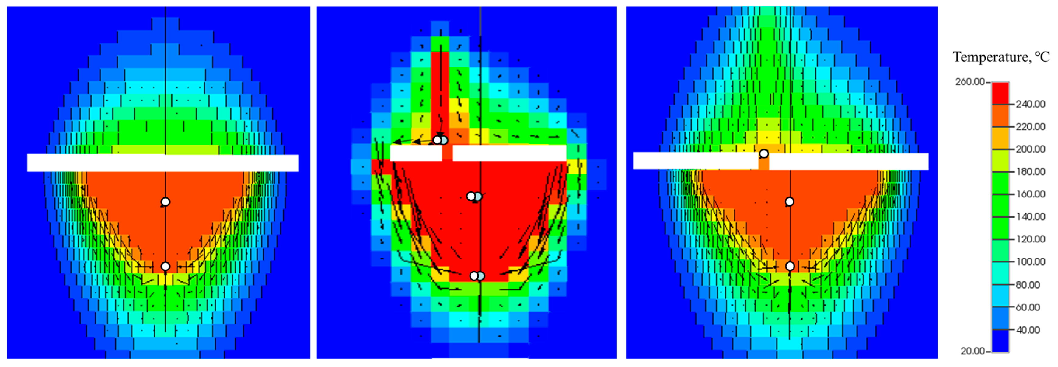
Experimental scheme and result analysis
Based on the actual in situ stress distribution in the F oilfield, the reservoir rock samples were subjected to a true tri-axial stress of 5000 kPa in the X-direction, 5500 kPa in the Y-direction, and 4500 kPa in the Z-direction, before initiating the multi-lateral SAGD reservoir dilation experiment (Figure 6).
The multi-lateral SAGD dilation experiment consists of three stages: low-pressure wellbore modification, dilation between SAGD injection and production wells, and dilation of the reservoir above the branches and steam-injection horizontal wells.
In the low-pressure wellbore modification stage, three steps are involved. Firstly, the steam-injection horizontal wells and production horizontal wells undergo a circulation wellbore cleaning process using an injection pressure of 500 kPa. Cleaning is performed by injecting through the long pipes and extracting through the short pipes. After cleaning, the short pipes are closed, and low-pressure dilation is conducted on the surrounding reservoir by injecting through the long pipes. Subsequently, the production wells are closed, and a polymer is injected into the injection well and branches to enhance water saturation and improve the homogeneity of the surrounding properties, aiming for uniform expansion. The injection pressure is strictly controlled within the range of 2300 to 3500 kPa, and the injection rate is set between 2 and 4 L/min. This stage results in the formation of a 1 to 2 m dilation zone around the injection and production wellbores and branches.
In the dilation between SAGD injection and production wells stage, after completing the low-pressure wellbore modification, the bottomhole pressure is further increased by increasing the injection volume. Simultaneously, the dilation zone of the steam-injection horizontal wells and production horizontal wells is expanded until connectivity is achieved between the injection and production horizontal wells. Injection pressures range from 3500 to 4000 kPa, and injection rates range between 4 and 5 L/min. This stage effectively improves the reservoir properties between the injection and production horizontal wells, establishes thermal and fluid connectivity between the wells, reduces circulation time in the SAGD preheating stage, and minimizes steam consumption. A 2 to 3 m dilation zone is formed around the injection and production wellbores, and noticeable temperature fields are observed between the wells.
In the dilation of the reservoir above the branches and steam-injection horizontal wells stage, after achieving connectivity between the injection and production horizontal wells, the production horizontal well is closed and sealed. The injection pressure of the steam-injection horizontal wells is adjusted to a value of 4000 to 4500 kPa, and a polymer with a viscosity of 50 mP·s is injected at a rate of 5 to 6 L/min. With increasing injection pressure and volume, the dilation range around the branches and above the steam-injection horizontal wells gradually increases, while the dilation range around the production horizontal well remains relatively constant. The experiment concludes when data at each monitoring point stabilize under the stable injection pressure. During this stage, the dilation zone above the steam-injection horizontal wells can extend up to a value of 3 to 8 m, and the dilation range around the branches reaches 3 to 5 m. This achieves the dilation and transformation of the reservoir above the steam-injection horizontal wells, improves reservoir properties, reduces the impact of heterogeneity, and facilitates the dilation of the steam chamber (Figure 7).

3.3. Numerical Simulation

The reservoir model is homogenous with parameters derived from the mean of the actual reservoir in Area A of the F oilfield. The initial reservoir temperature is 19.0 °C, and the initial reservoir pressure is 4600 kPa. Post discretization, the model dimensions in the x, y, and z directions are 35 m × 460 m × 21 m, with grid spacings of 1 m × 100 m × 0.5 m in the respective directions. All simulation runs were conducted using the commercial reservoir simulator (CMG’s STARS). The pertinent geomechanical parameters were obtained through tri-axial mechanical tests on actual core samples from the F oilfield conducted in a laboratory setting, with detailed specifications as presented in Table 2.
Based on the physical properties of the F oilfield reservoir and the rock mechanics characteristics, a coupled numerical model characterizing rock mechanics has been developed to simulate the dilation effects of the multi-lateral SAGD reservoir at each stage, with the objective of optimizing key operational parameters.
(1)
Pore pressure pre-processing stage: In this stage, the injection of 80 °C hot wastewater into the steam-injection well is conducted. The initial pore pressure for pre-processing in the Z18 well area is set at 6.65 MPa, which closely matches the minimum horizontal principal stress of the formation. The maximum pressure is controlled at 7.5 MPa. The injection volume is 350 cubic meters, and the injection duration spans 3 days.
(2)
Main wellbore and branch stress adjustment stage: During this stage, the steam-injection well continues to inject 80 °C hot wastewater, while the production well is shut down. The primary objective is to increase the pore pressure around the steam-injection well branch by approximately 1 m without interfering with the production well and without establishing communication between the steam-injection well and the production well. The optimal effect is achieved when the pressure in the steam-injection well reaches 1.2 times the minimum principal stress (8.25 MPa). The injection volume is 200 cubic meters, and the injection duration spans 2 days with a total treatment time-span of 5 days (Figure 8).
(3)
Branch pre-dilation stage: In this stage, a stepped pressure increase and decrease cycle is applied to the steam-injection well to maximize the dilation range. Concurrently, the production well circulates a polymer with a viscosity of 50 mPa·s, synchronized with the pressure variations in the steam-injection well. The primary objective is to achieve a dilation of approximately 1–2 m around the steam-injection well branch without causing plastic deformation or significant communication between the steam-injection well and the production well. The optimal effect is achieved when the maximum pressure during oscillation reaches 1.3 times the minimum principal stress (8.9 MPa). The injection volume is 650 cubic meters, and the injection duration spans 4 days.
(4)
Communication stage between steam-injection well and production well: During this stage, the pressure in both the steam-injection well and the production well is reduced through fluid drainage, followed by the dilation of the production well using hot wastewater to establish communication between the wells. The main objective is to create a weak connection between the steam-injection well and the production well. After the pressure reduction through fluid drainage in both wells, the production well circulates hot wastewater at 1.2 times the minimum principal stress. Simultaneously, the pressure difference between the steam-injection well and the production well is controlled within 1 MPa to achieve optimal inter-well communication. The injection volume is 30 cubic meters, and the injection duration is 1 day.
(5)
Large-volume dilation stage above the steam-injection well: In this stage, the steam-injection well injects 80 °C hot wastewater, while the production well circulates a polymer with a viscosity of 100 mPa·s, synchronized with the pressure variations in the steam-injection well. The primary objective is to achieve a dilation of 5–8 m above the steam-injection well without affecting the overlying formation. The optimal effect is achieved when the injection pressure reaches 1.4 times the minimum principal stress (9.2 MPa) (Figure 9). Too low a pressure results in an unclear dilation effect, while excessive pressure leads to significant heterogeneity. The injection volume is 2000 cubic meters, and the injection duration spans 10 days.
To optimize the reservoir upgrading and dilation process in the Xinjiang F oilfield, the study of a heterogeneous model of a typical well pair suggests the adoption of a segmented dilation approach during the inter-well communication stage. The reservoir in this well pair exhibits significant heterogeneity, particularly in the horizontal sections where interbeds are present. Without segmented expansion, it would be challenging to effectively improve the heterogeneity between wells, resulting in low recovery efficiency at the toe of the horizontal well.
The segmented dilation approach involves using high-viscosity polymers to seal the well sections with favorable reservoir properties initially. This helps to isolate those sections and prevent excessive fluid flow. Subsequently, the poorly performing sections are expanded using low-viscosity polymers, which allow for an improved fluid flow and the dilation of the reservoir.
Simulation results demonstrate that implementing segmented dilation can lead to significant improvements in permeability heterogeneity between wells. Prior to expansion, the permeability contrast between different sections may be around 5, indicating a significant difference in flow properties. However, after segmented expansion, the permeability contrast can be reduced to approximately 2 (Figure 10), indicating a more balanced and homogeneous distribution of flow properties between wells.

4. Optimization of the Multi-Lateral SAGD Configuration

In conventional SAGD, two parallel horizontal wells are used, one positioned above the other, to achieve the main objective of heating the oil reservoir by continuously injecting steam into the upper well. This process results in the downward movement of the heated crude oil, along with condensed steam, due to gravitational forces, which is then extracted from the lower production well.
In multi-lateral horizontal well SAGD with steam injection, the production well remains unchanged, but modifications are made to the steam-injection well to incorporate branching. These branches are designed to incline upward along the horizontal section, with an optimized inclination angle and branch length based on reservoir conditions and technical requirements. To accurately represent the three-dimensional shape of the upward-inclined branches, the upward inclination is decomposed into vertical and horizontal displacements relative to the horizontal well section (Figure 11).
Branching into the reservoir has three primary effects:
  • It expands the interface between the oil reservoir and the steam-injection wellbore, augmenting the steam injection capacity and enhancing the reservoir’s steam absorption capability under similar pressure conditions.
  • It expands the interface between the oil reservoir and the steam injection wellbore, augmenting the steam injection capacity and enhancing the reservoir’s steam absorption capability under similar pressure conditions.
  • It expands the interface between the oil reservoir and the steam injection wellbore, augmenting the steam injection capacity and enhancing the reservoir’s steam absorption capability under similar pressure conditions.
A numerical model of a typical well pair is established for the Xinjiang F oilfield, based on its reservoir conditions. Taking into account the practical aspects of the field, the SAGD well pair is designed with a horizontal section length of 450 m. The production well is positioned 2 m above the bottom of the oil layer, with a vertical spacing of 5 m between the steam-injection well and the production well.
Given the mechanisms and characteristics of production in dual horizontal well SAGD development, the optimization of branching in the multi-lateral steam-injection horizontal well focuses on three key aspects:
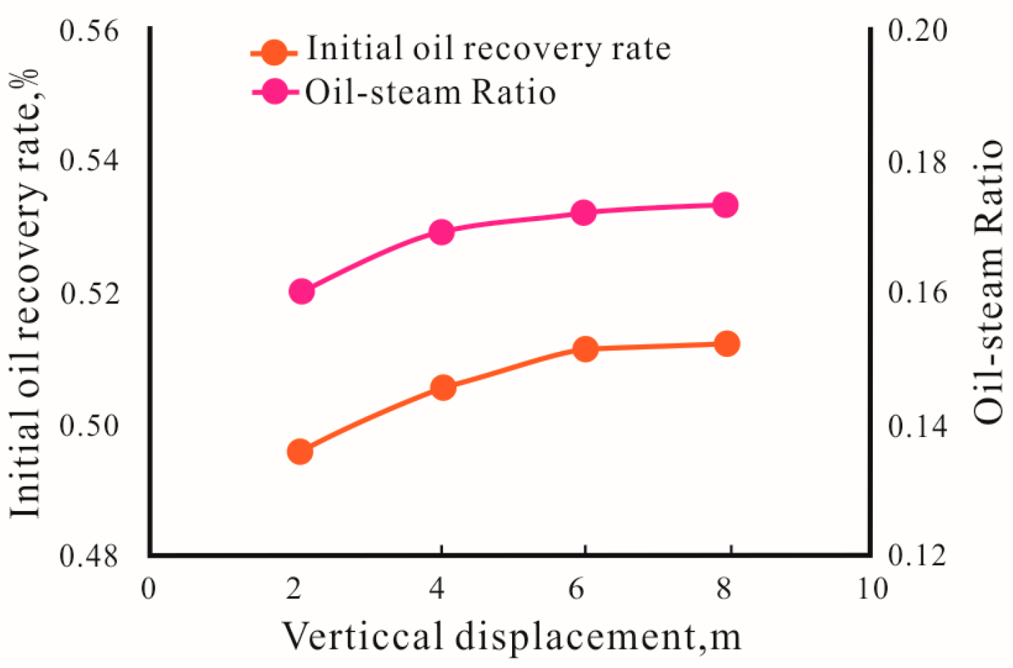
  • The relative positioning of the branches in relation to the main wellbore, specifically considering the vertical and horizontal displacements of the branches when inclined upward at a specific angle.
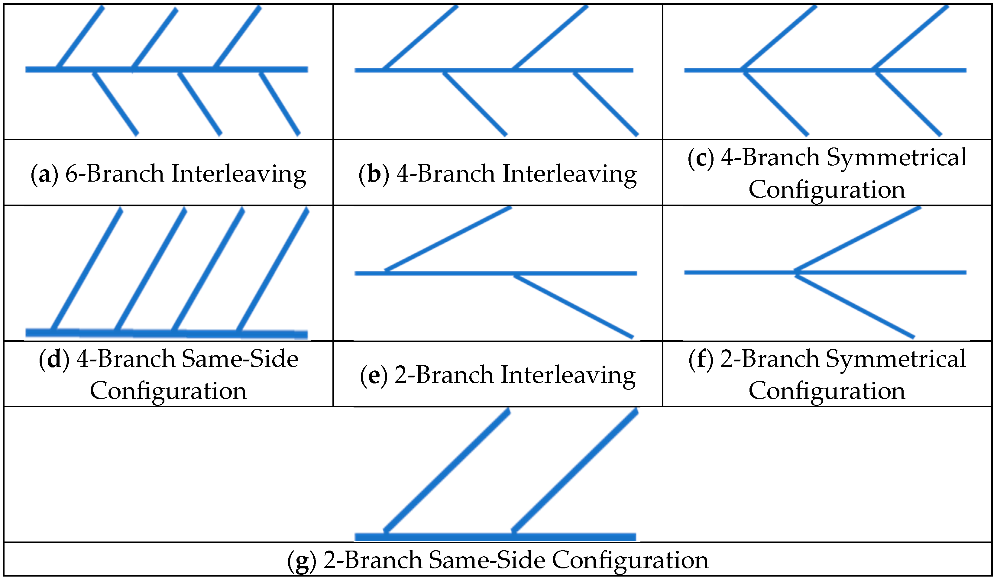
  • Determining the number of branches and their distribution with respect to the main wellbore.
  • Strategically positioning and orienting the branches in the presence of interbeds.
(1)
The spatial position of the upward branches relative to the main wellbore
The relative positioning of the branches in relation to the main wellbore plays a crucial role in determining the morphology of multi-lateral steam-injection wells. When the length of the branches remains constant, increasing the horizontal displacement between the branches and the main wellbore results in a larger controlled area of the branch wellbore and a greater area affected by steam. However, as the distance between them increases, the time required to establish a drainage pathway between the branches and the production well also lengthens, leading to a longer thermal communication time. Consequently, an optimal spatial position exists for the upward branches.
Simulations were conducted to analyze the production performance for varying horizontal displacements of the branches, ranging from 5 m to 30 m (Figure 12). The findings demonstrate that as the horizontal displacement of the branches increases, the initial oil production rate and oil-to-steam ratio also rise, albeit with a diminishing increment beyond a 20 m horizontal displacement. Likewise, simulations were performed for different vertical displacements of the branches, ranging from 2 m to 8 m (Figure 13). The results indicate that as the vertical distance between the branches and the main wellbore increases, the increment in the initial oil production rate and oil-to-gas ratio becomes less significant. Once a vertical displacement of 6 m is reached, the initial oil production rate exhibits minimal further increase. Analysis suggests that when the steam chamber rises to submerge the branches in the SAGD development, the branches lose their effectiveness.
In conclusion, it is recommended to limit the horizontal displacement of the branches to a maximum of 20 m and the vertical displacement to a maximum of 6 m.
(2)
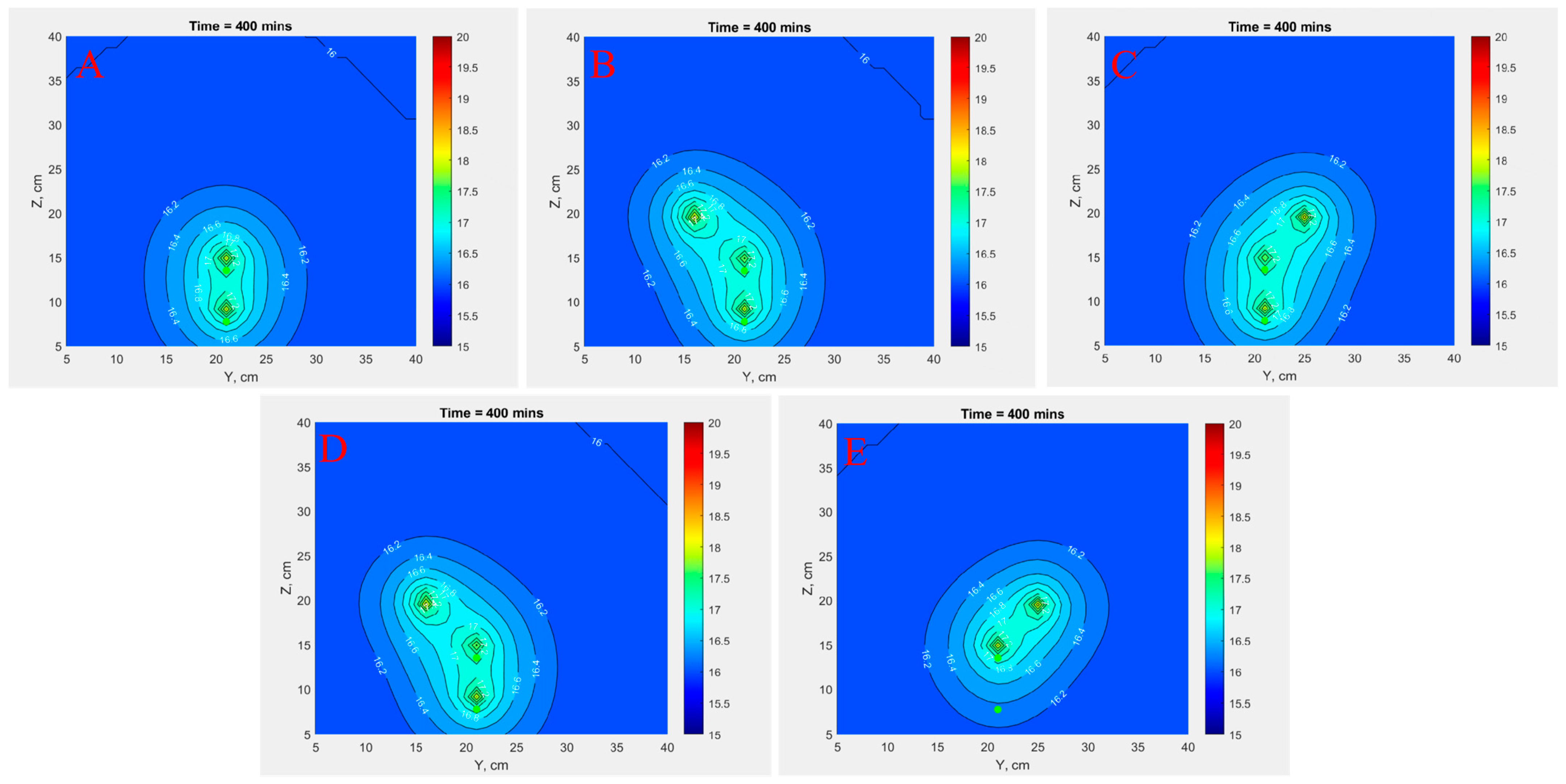
The number of branches and their distribution relative to the main wellbore
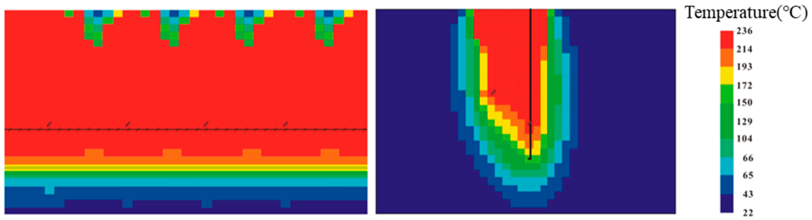
The number and distribution of branches within the steam-injection well are vital factors influencing steam distribution and steam chamber development. When the total length of the branches remains constant, and the horizontal and vertical displacements of the branches are fixed, seven distinct scenarios are devised to assess the effects of branch number and distribution on steam distribution (Figure 14).
Simulations were performed for each of these scenarios to analyze their influence on steam distribution and steam chamber development. By comparing the outcomes of these various branch configurations, valuable insights can be obtained concerning the optimal number and pattern of branch distribution.
Maintaining a constant total length of branches, a smaller number of branches results in longer individual branch lengths. Consequently, this leads to a wider range of steam distribution, a higher cumulative oil-to-steam ratio (COSR), and increased recovery efficiency. In terms of steam chamber development, the absence of branches or the presence of branches on only one side of the main well yield unsatisfactory results (Figure 15). In comparison to configurations without branches, symmetric branch distribution, or distribution on the same side, the configuration with alternating branch distribution demonstrates the most favorable outcomes (Table 3).
Analysis suggests that the presence of branches creates additional pathways for steam flow, effectively extending the length of the flow channels and improving production. When branches are arranged in an alternating distribution, they contribute evenly to the development and expansion of steam chambers along the main well. As a result, this configuration surpasses configurations with symmetric or same-side branch distribution.
When economic factors are not a constraint and there are no limitations on the total length of branches, simulation results reveal that a larger number of branches exerts a more pronounced positive influence on production performance.
(3)
The relative position of the branches to interbeds
The primary goal of the multi-lateral SAGD development is to mitigate the influence of interbeds above the steam-injection wells and effectively drain the reservoirs situated above them. The relationship between the branches and interbeds significantly impacts the production performance of the well pair. To assess this impact, two representative interbeds, measuring 100 m in length and extending laterally for 30 m, are positioned 3 m above the steam-injection well. Simulations are conducted to compare three scenarios: branches not penetrating the interbeds, branches penetrating the interbeds, and no branches. Results show that when branches penetrate the interbeds, peak production rates increase, leading to superior production performance. This occurs because the branches disrupt the integrity of the interbeds, creating drainage pathways and accessing the reservoirs above in advance. Compared to the scenario without branches, peak production rates increase by 7.1 t/d (Figure 16a), recovery efficiency improves by 3.8% (Figure 16b), and the CSOR increases by 0.012 when branches penetrate the interbeds.

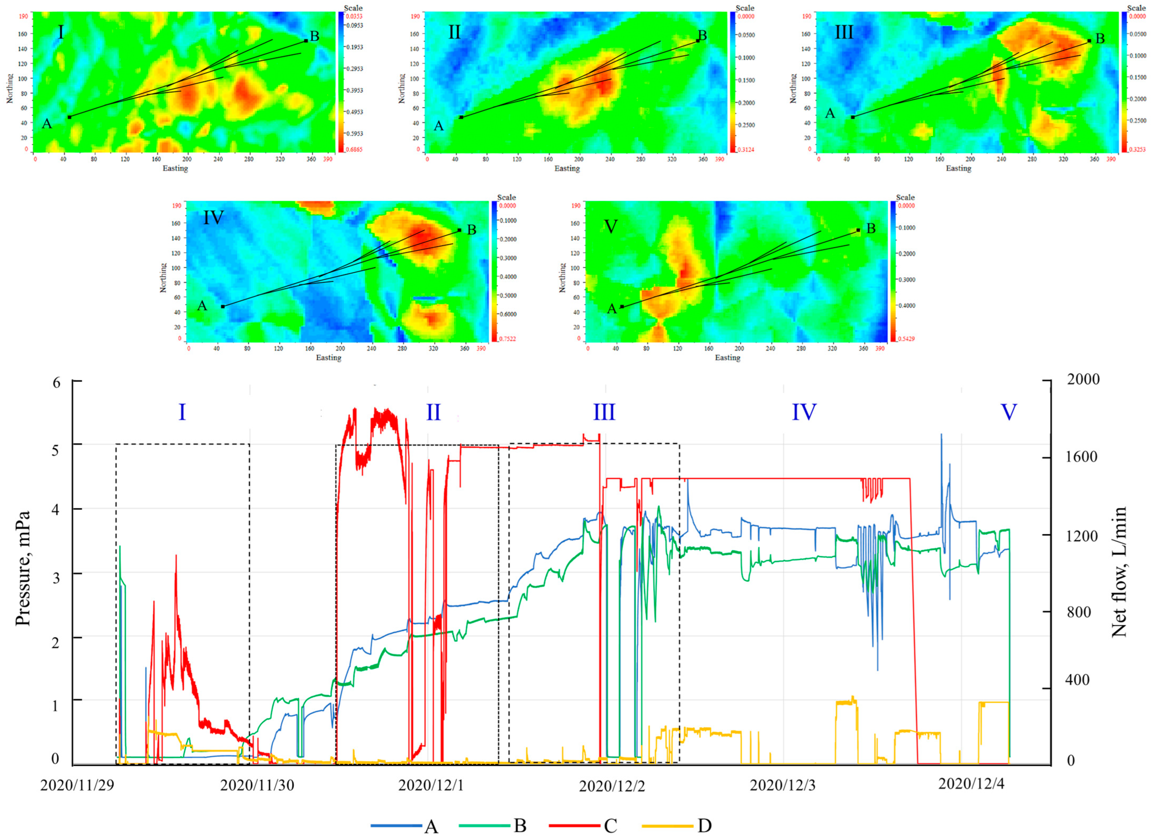
5. Pilot Production Performance

The SAGD reservoir segmented dilation was implemented at the A well pair of the F oilfield in 2020. In the Z18 area of the F oilfield, within Well A, the horizontal section measures 322 m in length. Above the steam-injection well, three branches were successfully drilled, each with a length of 100 m. The average permeability of this well section stands at 958 millidarcies (mD), with an average oil saturation of 64.7%.
This well was put into operation in 2020, primarily focusing on reservoir enhancement and expansion during its initial phase. Simultaneously, it underwent comprehensive monitoring throughout the expansion process using microseismic monitoring. The expansion process consisted of five key stages: wellbore pressure pre-treatment, stress-based expansion, staged section expansion, significant volume modification above Well I, and inter-well communication. The entire expansion process was completed within a span of 8 days, utilizing a total of 1251 cubic meters of injection fluid. According to the monitoring results, each stage of the sectional expansion exhibited distinct signals in the well section and branching locations (Figure 17).
Overall, the preheating period for Well A lasted for 90 days, consuming a total of 1.89 × 10⁴ tons of steam. This resulted in a 50% reduction in preheating time compared to well sections in the same region with similar reservoir properties, accompanied by a 30% reduction in steam consumption. After transitioning to production, Well A achieved a daily oil production rate of 15 tons, with an oil-to-steam ratio of 0.18. This represents a 20% improvement in oil production rate compared to well sections in the same region with similar reservoir properties, resulting in a 0.01 increase in the oil-to-steam ratio. On-site application of the results indicates that this study can serve as a valuable reference for optimizing construction parameters in the SAGD (steam-assisted gravity drainage) enhancement and expansion of strongly heterogeneous reservoirs.

6. Conclusions

(1)
Multi-lateral SAGD in strongly heterogeneous heavy oil reservoirs in Xinjiang was proposed and investigated in this study. Based on the experimental and numerical simulation results, this approach can effectively break interbeds and improve production performance. The tri-axial experiment results indicate that the rock formations in the heavy oil reservoirs of the F oilfield exhibit significant shear dilation effects under low confinement pressure conditions, with a volumetric dilation capacity of up to 7%. By employing the multi-lateral SAGD approach in conjunction with reservoir segmented dilation, the pore pressure in the vicinity of the branches and interbeds can be altered, creating high-porosity and high-permeability dilation zones. This facilitates the establishment of independent channels for steam injection and oil drainage through the branches, ultimately leading to increased oil production rates in strongly heterogeneous reservoirs.
(2)
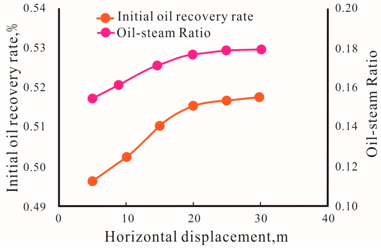
Based on the numerical simulation results, the branches should be strategically deployed in an interleaved manner, with a horizontal displacement of 20 m and a vertical displacement of 6 m. The best results are achieved when the branches intersect the interbeds, allowing for enhanced steam chamber conformance and volume.
(3)
Operational strategies indicate that dilation zones of 3–8 m can be created above the steam-injection horizontal wells and around the branches in the reservoir during the dilation of SAGD steam chambers. It is advisable to limit the maximum volume of dilation fluid used for hydraulic dilation to less than 2000 m3. Additionally, the SAGD steam-injection pressure should be lower than the minimum horizontal principal stress at the bottom of the cap rock. These findings help ensure optimal reservoir dilation and incremental production performance while maintaining the integrity of the cap rock.

Author Contributions

Conceptualization, C.L.; methodology and writing, Y.G.; investigation, Y.W. and W.H.; review and editing, J.L. All authors have read and agreed to the published version of the manuscript.

Funding

This research was funded by the China National Key Project (2016ZX05031) and the Science and Technology Project of CNPC (2019B-1411).

Institutional Review Board Statement

Not applicable.

Informed Consent Statement

Not applicable.

Data Availability Statement

Not applicable.

Acknowledgments

The authors gratefully acknowledge the financial support of the China National Key Project (2016ZX05031) and the Science and Technology Project of CNPC (2019B-1411). The valuable comments made by the anonymous reviewers are also sincerely appreciated.

Conflicts of Interest

The authors declare no conflict of interest.

References

  1. Butler, R.M. Steam-Assisted Gravity Drainage: Concept, Development, Performance and future. JCPT 1994, 32, 44–50. [Google Scholar] [CrossRef]
  2. Ma, Z.; Leung, J.Y. A knowledge-based heterogeneity characterization framework for 3D steam-assisted gravity drainage reservoirs. Knowl.-Based Syst. 2020, 192, 105327. [Google Scholar] [CrossRef]
  3. Liu, H.; Cheng, L.; Huang, S.; Jia, P.; Chen, M. Evolution characteristics of SAGD steam chamber and its impacts on heavy oil production and heat consumption. Int. J. Heat Mass Transf. 2018, 121, 579–596. [Google Scholar] [CrossRef]
  4. Gao, C.; Leung, J.Y. Techniques for fast screening of 3D heterogeneous shale barrier configurations and their impacts on SAGD chamber development. SPE J. 2021, 26, 2114–2138. [Google Scholar] [CrossRef]
  5. Ma, Z.; Leung, J.Y. Integration of data-driven models for characterizing shale barrier configuration in 3D heterogeneous reservoirs for SAGD operations. In Proceedings of the SPE Canada Heavy Oil Conference, Calgary, AB, Canada, 13–14 March 2018; SPE: Calgary, AB, Canada, 2018; p. D022S003R001. [Google Scholar]
  6. Xu, J.; Chen, Z.; Cao, J.; Li, R. Numerical study of the effects of lean zones on SAGD performance in periodically heterogeneous media. In Proceedings of the SPE Canada Heavy Oil Conference, Calgary, AB, Canada, 10–12 June 2014; SPE: Calgary, AB, Canada, 2014; p. D021S005R007. [Google Scholar]
  7. Amirian, E.; Leung, J.Y.; Zanon, S.D.; Dzurman, P.J. An integrated application of cluster analysis and artificial neural networks for SAGD recovery performance prediction in Heterogeneous Reservoirs. In Proceedings of the SPE Canada Heavy Oil Conference, Calgary, AB, Canada, 10–12 June 2014; SPE: Calgary, AB, Canada, 2014; p. D011S004R003. [Google Scholar]
  8. Kumar, A.; Hassanzadeh, H. A qualitative study of the impact of random shale barriers on SAGD performance using data analytics and machine learning. J. Pet. Sci. Eng. 2021, 205, 108950. [Google Scholar] [CrossRef]
  9. Li, X.; Liu, H.; Luo, J.; Jiang, H.; Wang, H. 3D physical simulation on dual horizontal well SAGD in heterogeneous reservoir. Acta Pet. Sin. 2014, 35, 536. [Google Scholar]
  10. Hampton, T.; Kumar, D.; Azom, P.; Srinivasan, S. Analysis of impact of thermal and permeability heterogeneity on SAGD performance using a semi-analytical approach. In Proceedings of the SPE Heavy Oil Conference-Canada, Calgary, AB, Canada, 11–13 June 2013; OnePetro: Richardson, TX, USA, 2013. [Google Scholar]
  11. Stone, T.W.; Law, D.H.S.; Bailey, W.J. Control of reservoir heterogeneity in SAGD bitumen processes. In Proceedings of the SPE Canada Heavy Oil Conference, Calgary, AB, Canada, 11–13 June 2013; SPE: Calgary, AB, Canada, 2013; p. SPE-165388. [Google Scholar]
  12. Govind, P.A.; Das, S.; Srinivasan, S.; Wheeler, T.J. Expanding solvent SAGD in heavy oil reservoirs. In Proceedings of the SPE International Thermal Operations and Heavy Oil Symposium, Calgary, AB, Canada, 20–23 October 2008; SPE: Calgary, AB, Canada, 2008; p. SPE-117571. [Google Scholar]
  13. Venkatramani, A.V.; Okuno, R. Mechanistic simulation study of expanding-solvent steam-assisted gravity drainage under reservoir heterogeneity. J. Pet. Sci. Eng. 2018, 169, 146–156. [Google Scholar] [CrossRef]
  14. Venkat Venkatramani, A.; Okuno, R. Steam-Solvent Coinjection under Reservoir Heterogeneity: Should ES-SAGD be Implemented for Highly Heterogeneous Reservoirs? In Proceedings of the SPE Canada Heavy Oil Conference, Calgary, AB, Canada, 15–16 February 2017; SPE: Calgary, AB, Canada, 2017; p. D021S008R003. [Google Scholar]
  15. Venkat Venkatramani, A.; Okuno, R. Characterization of Reservoir Heterogeneity for SAGD and ES-SAGD: Under What Type of Heterogeneity is ES-SAGD More Likely to Lower SOR? In Proceedings of the SPE Annual Technical Conference and Exhibition, San Antonio, TX, USA, 9–11 October 2017; OnePetro: Richardson, TX, USA, 2017. [Google Scholar]
  16. Kumar, A.; Hassanzadeh, H. Impact of shale barriers on performance of SAGD and ES-SAGD—A review. Fuel 2021, 289, 119850. [Google Scholar] [CrossRef]
  17. Al-Gosayir, M.; Leung, J.; Babadagli, T. Design of solvent-assisted SAGD processes in heterogeneous reservoirs using hybrid optimization techniques. J. Can. Pet. Technol. 2012, 51, 437–448. [Google Scholar] [CrossRef]
  18. Neeteson, N.; Heukelman, H.; Zhu, D.; Thompson, S. Evaluation, Implementation, and Operations of an FCD for SAGD Producer Wells. In Proceedings of the SPE Thermal Integrity and Design Symposium, Banff, AB, Canada, 19–21 November 2019; SPE: Calgary, AB, Canada, 2019; p. D021S005R001. [Google Scholar]
  19. Banerjee, S.; Hascakir, B. Flow control devices in SAGD completion design: Enhanced heavy oil/bitumen recovery through improved thermal efficiency. J. Pet. Sci. Eng. 2018, 169, 297–308. [Google Scholar] [CrossRef]
  20. Gohari, K.; Ortiz, J.; Abraham, A.; Moreno, O.B.; Irani, M.; Nespor, K.; Sanchez, J.; Betancur, A.; Bilic, J.; Duong, K.; et al. Investigating the Performance of Various FCD Geometries for SAGD Applications. In Proceedings of the SPE Thermal Integrity and Design Symposium, Banff, AB, Canada, 29–30 November 2021; OnePetro: Richardson, TX, USA, 2021. [Google Scholar]
  21. Riel, A.; Burton, R.C.; Vachon, G.P.; Wheeler, T.J.; Heidari, M. An Innovative Modeling Approach to Unveil Flow Control Devices’ Potential in SAGD Application. In Proceedings of the SPE Canada Heavy Oil Conference, Calgary, AB, Canada, 10–12 June 2014; SPE: Calgary, AB, Canada, 2014; p. D031S016R004. [Google Scholar]
  22. Nespor, K.; Chacin, J.; Ortiz, J.; Morter, J.; Romanova, U.; Bilic, J.; Gohari, K.; Becerra, O. An Overview of the Field Performance of Tubing Deployed Flow Control Devices in the Surmont SAGD Project. In Proceedings of the SPE Thermal Integrity and Design Symposium, Banff, AB, Canada, 19–21 November 2019; SPE: Calgary, AB, Canada, 2019; p. D031S009R002. [Google Scholar]
  23. Burke, L.; Ghazar, C. Flow control devices in SAGD-A system-based technology solution. In Proceedings of the SPE Thermal Integrity and Design Symposium, Banff, AB, Canada, 27–29 November 2018; SPE: Calgary, AB, Canada, 2018; p. D023S005R002. [Google Scholar]
  24. Yang, Z.; Sun, X.; Luo, C.; Xu, B.; Yang, B.; Li, B. Vertical-well-assisted SAGD dilation process in heterogeneous super-heavy oil reservoirs: Numerical simulations. Undergr. Space 2021, 6, 603–618. [Google Scholar] [CrossRef]
  25. Kamari, A.; Hemmati-Sarapardeh, A.; Mohammadi, A.H.; Hashemi-Kiasari, H.; Mohagheghian, E. On the evaluation of Fast-SAGD process in naturally fractured heavy oil reservoir. Fuel 2015, 143, 155–164. [Google Scholar] [CrossRef]
  26. Sarapardeh, A.H.; Kiasari, H.H.; Alizadeh, N.; Mighani, S.; Kamari, A. Application of fast-SAGD in naturally fractured heavy oil reservoirs: A case study. In Proceedings of the SPE Middle East Oil and Gas Show and Conference, Manama, Bahrain, 10–13 March 2013; SPE: Calgary, AB, Canada, 2013; p. SPE-164418. [Google Scholar]
  27. Ameli, F.; Mohammadi, K. A novel optimization technique for Fast-SAGD process in a heterogeneous reservoir using discrete variables and repetition inhibitory algorithm. J. Pet. Sci. Eng. 2018, 171, 982–992. [Google Scholar] [CrossRef]
  28. Mohammadi, K.; Ameli, F. Toward mechanistic understanding of Fast SAGD process in naturally fractured heavy oil reservoirs: Application of response surface methodology and genetic algorithm. Fuel 2019, 253, 840–856. [Google Scholar] [CrossRef]
  29. Dang, C.T.; Chen, Z.J.; Nguyen, N.T.; Bae, W. Fast-SAGD vs. SAGD: A comparative numerical simulation in three major formations of Alberta’s oil sands. In Proceedings of the SPE Canada Heavy Oil Conference, Calgary, AB, Canada, 12–14 June 2012; SPE: Calgary, AB, Canada, 2012; p. SPE-144149. [Google Scholar]
Figure 1. Typical reservoir lithology section of the Xinjiang F oilfield.
Energies 16 07351 g001
Figure 2. Comparison diagram of steam chamber development profiles between multi-lateral SAGD and conventional SAGD.
Energies 16 07351 g002
Figure 3. Dilation phenomenon of loose rocks caused by shear stress and pore pressure.
Energies 16 07351 g003
Figure 4. Rock mechanics test curve of the reservoir core in well A of the F oilfield. (a) Stress–strain curves under different confining pressures. (b) Volume dilation curves under different confining pressures.
Energies 16 07351 g004
Figure 5. Experimental device of the true tri-axial model.
Energies 16 07351 g005
Figure 6. Temperature distribution along the horizontal section of a large-scale physical model of reservoir dilation for multilateral SAGD.
Energies 16 07351 g006
Figure 7. Temperature distribution along the horizontal section of a large-scale physical model of reservoir dilation for multi-lateral SAGD. (AE represent the cross-sectional results of the side view in Figure 6).
Energies 16 07351 g007
Figure 8. Permeability changes around branches under different injection periods.
Energies 16 07351 g008
Figure 9. Comparison chart of permeability under different pressures after large-volume dilation above the steam-injection well.
Energies 16 07351 g009
Figure 10. Comparison of permeability distribution before and after unsegmented/segmented dilation of typical well pairs.
Energies 16 07351 g010
Figure 11. Schematic representation of the multi-lateral steam-injection horizontal well SAGD development configuration.
Energies 16 07351 g011
Figure 12. Comparison of the horizontal displacement production of different branches.
Energies 16 07351 g012
Figure 13. Comparison of the vertical displacement production of different branches.
Energies 16 07351 g013
Figure 14. Branch configuration scenarios.
Energies 16 07351 g014
Figure 15. Schematic diagram of temperature field distribution of the multi-lateral steam injection horizontal well SAGD (left—along wellbore profile; right—vertical wellbore profile).
Energies 16 07351 g015
Figure 16. Comparison of production effects with different branch and interbed relative positions. (a) Oil rate and CSOR are affected by branch location, and (b) recovery efficiency is affected by branch location.
Energies 16 07351 g016
Figure 17. Field operation curve and microseismic monitoring results of the typical well pair segmented expansion. (A—Injection well pressure; B—Production well pressure; C—Injection well net flow; D—Production well net flow; I—Wellbore pretreatment; II—Step-out expansion; III—Segmented expansion with branch well: plug the heel, expand the toe; IV—Segmented expansion with large-volume modification: plug the heel, expand the toe; V—Segmented expansion with minor-volume modification: expand the heel).
Energies 16 07351 g017
Table 1. Similarity of physical properties between remolded oil sand and outcrop oil sand in the physical simulation experiment.
Sample TypePhysical Property Parameters
Porosity
/%
Permeability
/mD
Young’s Modulus
/MPa
Unconfined Compressive Strength
/MPa
Density
/(g·cm−3)
Remolded oil sand291 6004101.31.96
Outcrop oil sand288006001.62.0
Table 2. The property values of the F oilfield model.
PropertyValue
Porosity28.0%
Horizontal permeability0.96D
Vertical permeability0.62D
Initial reservoir pressure at the depth of 445 m4.6 × 103 kPa
Initial reservoir temperature19.0 °C
Initial oil saturation66.0%
Formation compressibility5 × 10−5 kPa−1
Rock heat capacity2.1 × 106 J/m3·°C
Rock thermal conductivity2.0 × 105 J/m·day·°C
Average viscosity at 50 °C7.47 × 104 cp
Young’s modulus3.10 × 105 kPa
Poisson’s ratio0.08
Internal friction angle35.39°
Cohesion0.94 kPa
Coefficient of thermal expansion2.5 × 10−5/°C
Angle of dilation20°
Table 3. Comparison of production effects between different branch numbers and symmetrical conditions in steam-injection wells.
Symmetrical ConditionsCOSRRecovery Efficiency (%)
6-Branch Interleaving0.12550.6
4-Branch Interleaving0.12750.7
4-Branch Symmetrical Configuration0.12249.5
4-Branch Same-Side Configuration0.12550.6
1-Branch Interleaving0.12451.0
1-Branch Symmetrical Configuration0.12150.1
2-Branch Same-Side Configuration0.12350.4
No Branching0.11548.1
Disclaimer/Publisher’s Note: The statements, opinions and data contained in all publications are solely those of the individual author(s) and contributor(s) and not of MDPI and/or the editor(s). MDPI and/or the editor(s) disclaim responsibility for any injury to people or property resulting from any ideas, methods, instructions or products referred to in the content.

