Article

Influence of Interface Morphology on the Thermal Stress Distribution of SOFC under Inhomogeneous Temperature Field

1
School of Aerospace Engineering, North University of China, Taiyuan 030051, China
2
Beijing Tsing Aero Armament Technology Co., Ltd., Beijing 100190, China
3
Bi-Inspired and Advanced Energy Research Center, Department of Engineering Mechanics, Northwestern Polytechnical University, Xi’an 710129, China
*
Authors to whom correspondence should be addressed.
Energies 2023, 16(21), 7349; https://doi.org/10.3390/en16217349
Submission received: 26 September 2023 / Revised: 23 October 2023 / Accepted: 26 October 2023 / Published: 31 October 2023
(This article belongs to the Section A5: Hydrogen Energy)

Abstract

:
Excessive thermal stress can cause the failure of a solid oxide fuel cell (SOFC), and an inhomogeneous temperature field is one of the reasons for thermal stress in the cell. In the present work, the bi-dimensional thermo-mechanical coupling models of SOFCs with different interface morphologies including planar and corrugated cells are proposed. The temperature distribution of two types of cells under the action of heat conduction is analyzed. Further, the inhomogeneous temperature field caused by gas flow is used as the thermal load to compare the thermal stress distribution of planar and corrugated cells. The influence of interface morphology on the temperature distribution, stress distribution and the contribution of the temperature gradient to stress distribution are investigated. This research provides a reference for reducing thermal stress and improving the stability of SOFC.

1. Introduction

With the increasing demand for energy, the sustainable development of clean and efficient energy becomes more and more important and the new energy industry has received worldwide attention [1,2,3,4]. The solid oxide fuel cell (SOFC), as an electrochemical device operating at a high temperature, can convert the chemical energy of the fuel (hydrogen, marsh gas and so on) directly to electrical energy. It can break through the limitation of Carnot cycle, and the maximum conversion efficiency is 70% without heat utilization [5,6]. This advantage makes SOFC widely used in hybrid systems, such as micro combined heat and power systems for residential use [7], and hybrid systems with Stirling engines [8], with gas turbines [9], steam turbines [10] and biomass gasification processes [11].
A typical SOFC unit is a sandwich structure, which includes the interconnector, the channel and the positive electrode–electrolyte–negative electrode (PEN) structure, which usually works at high temperatures from 600 °C to 1000 °C [12]. The electrochemical properties of SOFC are closely coupled with the thermal characteristics, that is to say, it is necessary to maintain a suitable high temperature environment for efficient electrochemical reactions. The higher the temperature, the smaller the internal resistance, the greater the power generation capacity and the higher the output efficiency [13,14]. To a certain extent, this suitable high temperature can be advantageous because released heat can be made profitable for other thermal systems. However, the excessive temperature change or temperature gradient and the thermal expansion coefficient difference in the SOFC structure may cause large residual stresses, crack initiation and crack propagation in the electrolyte or electrodes, and it can even cause the SOFC structure to fail [6,15]. For instance, the interfacial crack begins to propagate gradually under an excessive thermal load until an interface delamination is generated when the crack initiation occurs at the anode–electrolyte interface or cathode–electrolyte interface [6,16]. The ohmic resistance in the interface delamination region increases exponentially after interface delamination occurs, which hinders the transfer of ions and electrons between the electrolyte and electrode, causing the interface delamination region to lose its electrochemical potential [17,18,19,20]. Therefore, temperature distribution and thermal stress have become important problems in the study of SOFC.
Many studies have been focused on the thermal safety properties of planar SOFC or tubular SOFC under the homogeneous temperature field. A thermo-electrical coupling mode of a planar SOFC at a homogeneous temperature of 900 °C was solved using a self-programming algorithm by Zitouni et al. [12]. The temperature, the mass fractions of hydrogen and water and their locations were discussed for the electrodes and the electrolyte with different geometric configurations. When the structure is influenced by the chemical reaction, Joule effect and activation overpotential, its maximum temperature was located between the interface of the anode and electrolyte, at the electrolyte and at the cathode, respectively. A finite difference calculation program was developed by LeMasters [21], which can be used to calculate the thermal stresses in the SOFC, preliminarily. This calculation program was applied to the new heat sources, flow conditions and various properties of the fluids. The thermal stresses of a five-stack two-dimensional planar SOFC model and a single three-dimensional planar SOFC model were investigated by Valluru [22]. In the single three-dimensional planar SOFC model, the maximum thermal stress was produced at the electrolyte edge, which causes the SOFC structure to fail. The conversion efficiency of fuel to electrical energy is reduced because oxygen reacts with fuel by an uncontrolled means at the electrolyte edge. An analytical model for the electrochemical performance, structural reliability and thermal losses for a planar, circular, electrolyte-supported miniaturized SOFC at the temperature range from 600 °C to 1000 °C was presented by Srikar et al. [23]. Over the range of parameters considered, thermal losses were significantly higher than the electrochemical power produced. A multi-dimensional, multi-component, non-isothermal and dynamic model were presented by Tseronis et al. [24] to study the energy and mass transport and the electrochemical phenomena take place in the SOFC. The composition and temperature distribution were effectively predicted using this dynamic model. The polarization curves were generated to examine the effects of various design and operating parameters on the SOFC performance. Therefore, the major stake of current research in the field of the SOFC is to decrease the operating temperature while preserving optimal properties.
In addition to planar SOFC, the tubular SOFC applied in many power systems was also investigated by many scholars. The tubular SOFC was developed by Westinghouse firstly [25]. The operation time of kW-class tubular SOFC stacks is over 5000 h [26]. The tubular SOFC has a good mechanical strength to withstand the thermal expansion. But the power density of the tubular SOFC (diameter > 15 mm) is only 0.2 W/cm2 approximately [27], which is much lower than that of the planar SOFC due to the long current collection path. The effective method to improve the power density is to increase the ratio of surface area to volume, which leads to the high volumetric stack power density [28,29,30]. The manufacturing details of a cubic microtubular (diameter < 5 mm) SOFC stack was reported by Funahashi et al. [31]. Kendall et al. [32,33] successfully used the microtubular SOFC as the auxiliary power sources for a LNG truck and a battery-driven mobile robot. A 700 W microtubular SOFC stack with a high-power density was designed and manufactured by Lee et al. [34]. In addition, the temperature gradient along the structure axis increases with the decrease in the diameter of tubular SOFC because the decrease in the tube diameter resulted in an increase in volumetric heat generation [28]. It has been found that the temperature gradient in the tubular SOFC is larger than 30 °C/cm when the tube diameter is 1.8 mm [35], while the temperature gradient is smaller than 5 °C/cm when the tube diameter is larger than 15 mm [36,37].
In recent years, compared with traditional planar SOFC, the corrugated SOFC has received a lot of attention because it has higher fuel utilization, lower temperature differences and higher current density [38,39,40,41,42,43] by enlarging the triple phase boundary length of the cell [44,45]. Similar to typical planar SOFC, the anode-supported corrugated SOFC consists of three components, i.e., anode, cathode and electrolyte, and is a dense film of only a few tens of microns thick or even thinner, but the interfaces between electrodes and the electrolyte are corrugated rather than flat [15,46]. However, many previous studies mainly focused on the thermal safety properties of planar and tubular SOFC under a homogeneous temperature field, while there was less research on the thermo-mechanical model and thermal stress problem of the corrugated SOFCs under inhomogeneous temperature fields.
Therefore, the bi-dimensional thermo-mechanical coupling model has been proposed in the present work to investigate the heat conduction process and thermal stress distribution of SOFC with different interface morphology including planar and corrugated SOFCs. The inhomogeneous temperature field caused by co-flow in gas is used as the thermal load to investigate the thermal stress distribution of SOFC. The influence of interface morphology on the temperature distribution, stress distribution and the contribution of temperature gradient to stress distribution is also investigated. In addition, the interface temperature and thermal stress distribution are compared between planar and corrugated SOFCs. The results obtained by this investigation can provide a reference for reducing thermal stress and improving stability of SOFC.

2. Materials and Methods

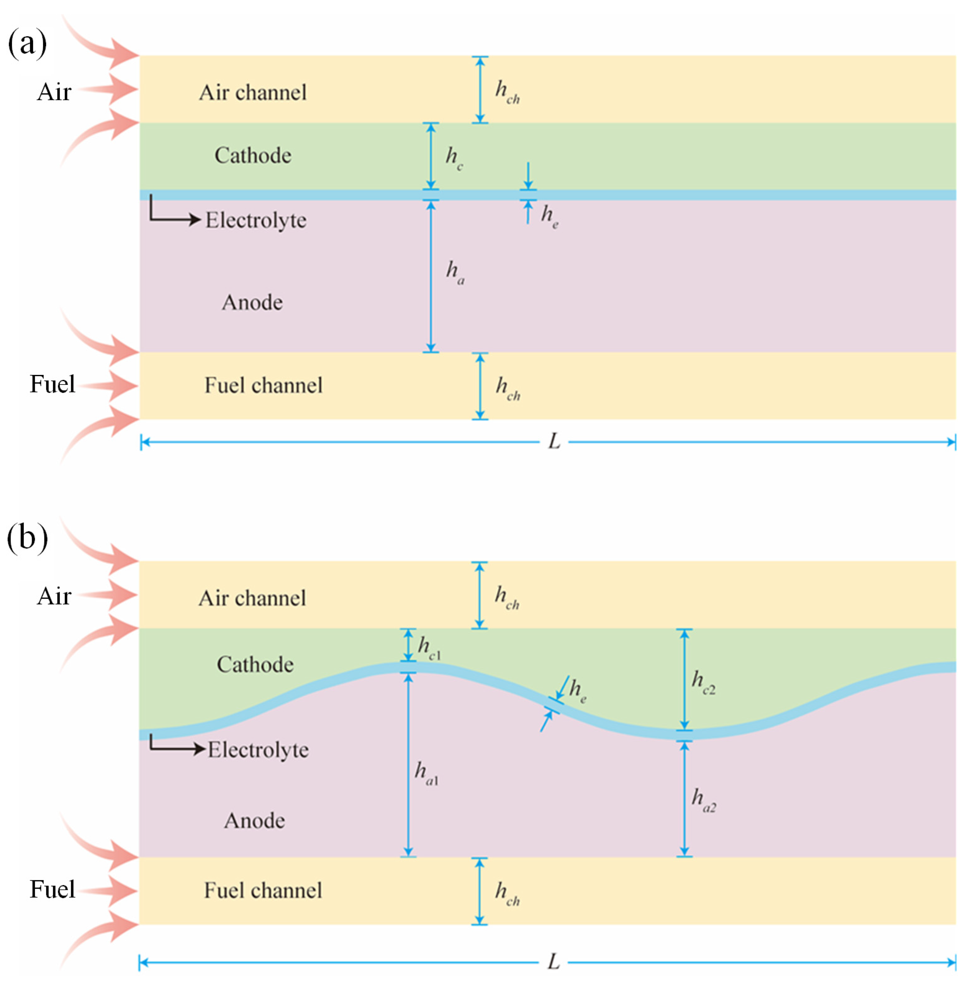
2.1. Geometry Structures

The SOFC structure unit consists of the interconnector, the channel and the positive electrode–electrolyte–negative electrode (PEN) structure. The PEN structure is the main body of the cell, which consists of a dense gas-tight electrolyte sandwiched by an anode and cathode, which present enough porosity for allowing the fuel and air to go into and back from the cell active sites. In addition, the fuel channel and the air channel are located outside the anode and cathode, respectively. The difference between the planar SOFC and corrugated SOFC is the interface morphology of the electrolyte and electrodes, but their basic PEN components are same. The structure diagrams of planar and corrugated SOFCs with different interface morphologies are shown in Figure 1. The width of both cells is L and the thickness of the air channel and fuel channel are hch. In terms of the planar SOFC, the thickness of each PEN component is uniform and all interfaces are flat. It can be seen from Figure 1a that the thicknesses of the anode, electrolyte and cathode of planar SOFC are ha, he, and hc, respectively. While in terms of the corrugated SOFC, only the thickness of the electrolyte is uniform, but its structure is corrugated, which results in a corrugated interface between the electrolyte and electrode, and a non-uniform thickness of the cathode and anode. It can be seen from Figure 1b that the thickness of the electrolyte of corrugated SOFC is also he, and the thicknesses of the anode and cathode at their peak are ha1 and hc1, and at their trough are ha2 and hc2, respectively. In order to ensure that the overall thickness of corrugated SOFC is consistent with that of planar SOFC, the following relationship exists between the electrode thicknesses:
ha = (ha1 + ha2)/2
hc = (hc1 + hc2)/2

2.2. Material Models

The electrode materials of the planar and corrugated SOFCs applied in the analytical model are nickel yttria-stabilized zirconia composites (Ni-YSZ) for the anode and strontium-doped lanthanum manganite (LSM) for the cathode. The electrolyte material is yttria-stabilization zirconia (YSZ), which has great ionic conductivity, low electron conductivity, fine compacting degree, high thermal compatibility and high mechanical strength [47,48,49]. The isotropic linear-elastic and homogenized model is employed to describe all materials. The material properties including thermal conductivity, density and specific heat are used to characterize the thermal conduction behavior of the cell; while the temperature-dependent material properties including the elastic modulus, Poisson’s ratio and thermal expansion coefficient are used to characterize the thermal stress behavior of the cell. All material properties of the electrodes and electrolyte are listed in Table 1 [50,51,52,53,54,55].

2.3. Finite Element Model

The purpose of this paper is to compare the temperature distribution and stress distribution of planar SOFC and corrugated SOFC under heat conduction. Therefore, the heat conduction process and thermal stress distribution of two types of SOFCs are simulated using the numerical software ABAQUS. The finite element models of two processes are basically the same. For the heat conduction process, the finite element model includes the fuel channel, air channel and PEN structure. And in order to analyze the heat conduction process of the SOFC, the surface heat flux ϕ is set on the left side of the two channels (x = 0) and the specific values of different components of the cell are determined according to the following equation:
ϕ = λT/l
where λ is the thermal conductivity of the material, ∆T is the temperature difference between room temperature and the operating temperature of the cell, l is the length of the cell.
For heat conduction process, the initial temperature of the model is room temperature, and the maximum temperature of the cell reaches operating temperature, i.e., about 1073 K, after a period of time under the action of heat flow. In addition, the residual thermal stress in the preparation process of SOFC is not taken into account in the finite element model. Due to the influence of geometric characteristics and thermal conductivity of the cell, the temperature field of the SOFC is inhomogeneous. Furthermore, the inhomogeneous temperature field is used as the thermal load of the cell to study its thermal stress distribution. For thermal stress process, the finite element model only includes the PEN structure. The boundary condition of the finite element model is set to axisymmetric, i.e., ux = 0, about the Y axial when x = L, while the displacement along the Y axial direction is fixed, i.e., uy = 0, when x = L and y = 0.
The 4-node thermally coupled quadrilateral element (CPE4T) [56] is used to study the heat conduction process of SOFC based on plane strain assumption, while the 4-node quadrilateral element (CPE4) [56] is used to study the thermal stress distribution of SOFC. The whole finite element model consists of 22,800 elements and 23,177 nodes for planar SOFC and 26,010 elements and 26,402 nodes for corrugated SOFC, and the width of each element is approximately 0.01 mm.

3. Results and Discussion

The heat flow acts on the left side of the gas channel along the X direction, then the heat is conducted inside the SOFC until the temperature of the PEN structure reaches the operating temperature. Based on the heat conduction process, the influence of interface morphology on the temperature distribution of SOFC is studied. Furthermore, the effect of interface morphology on the stress distribution of SOFC under the obtained inhomogeneous temperature field is also discussed.

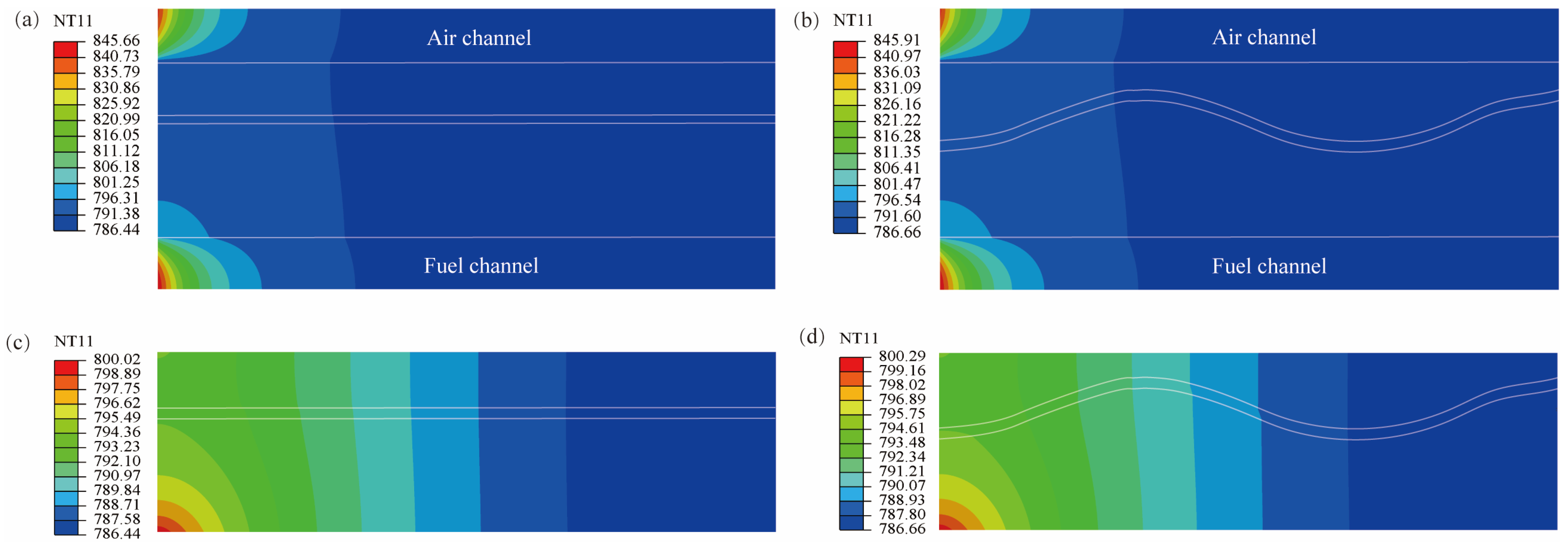
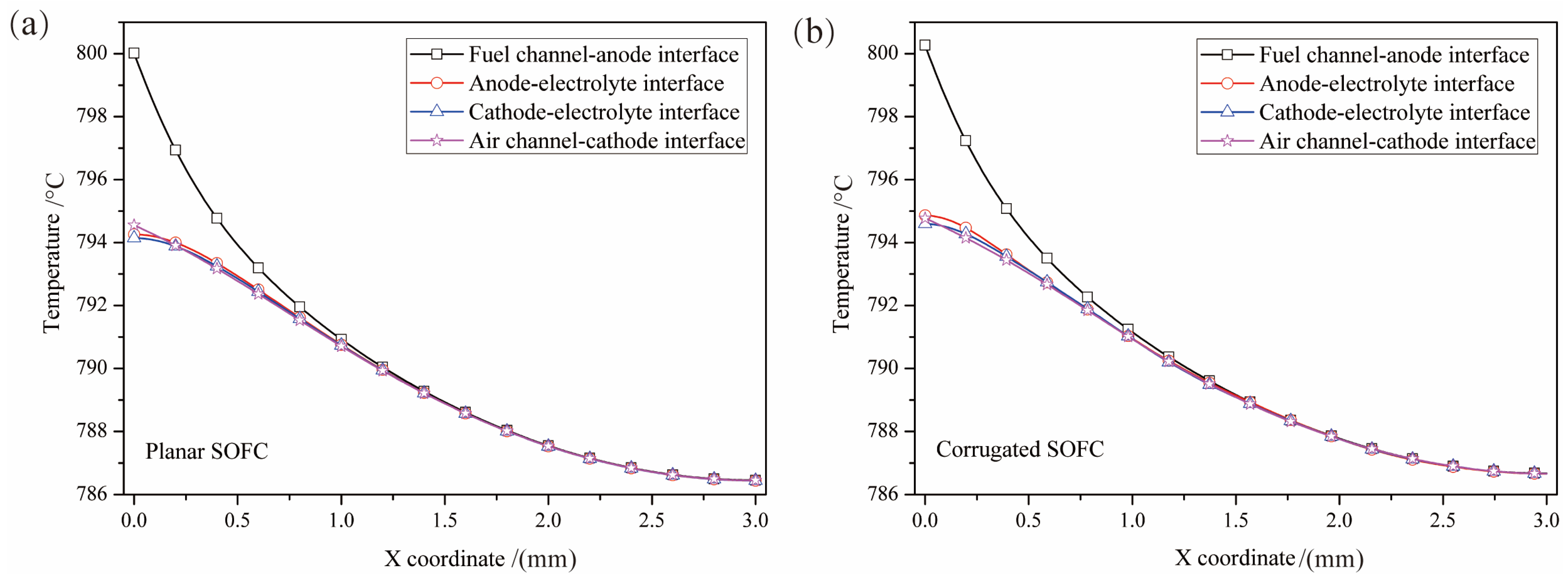
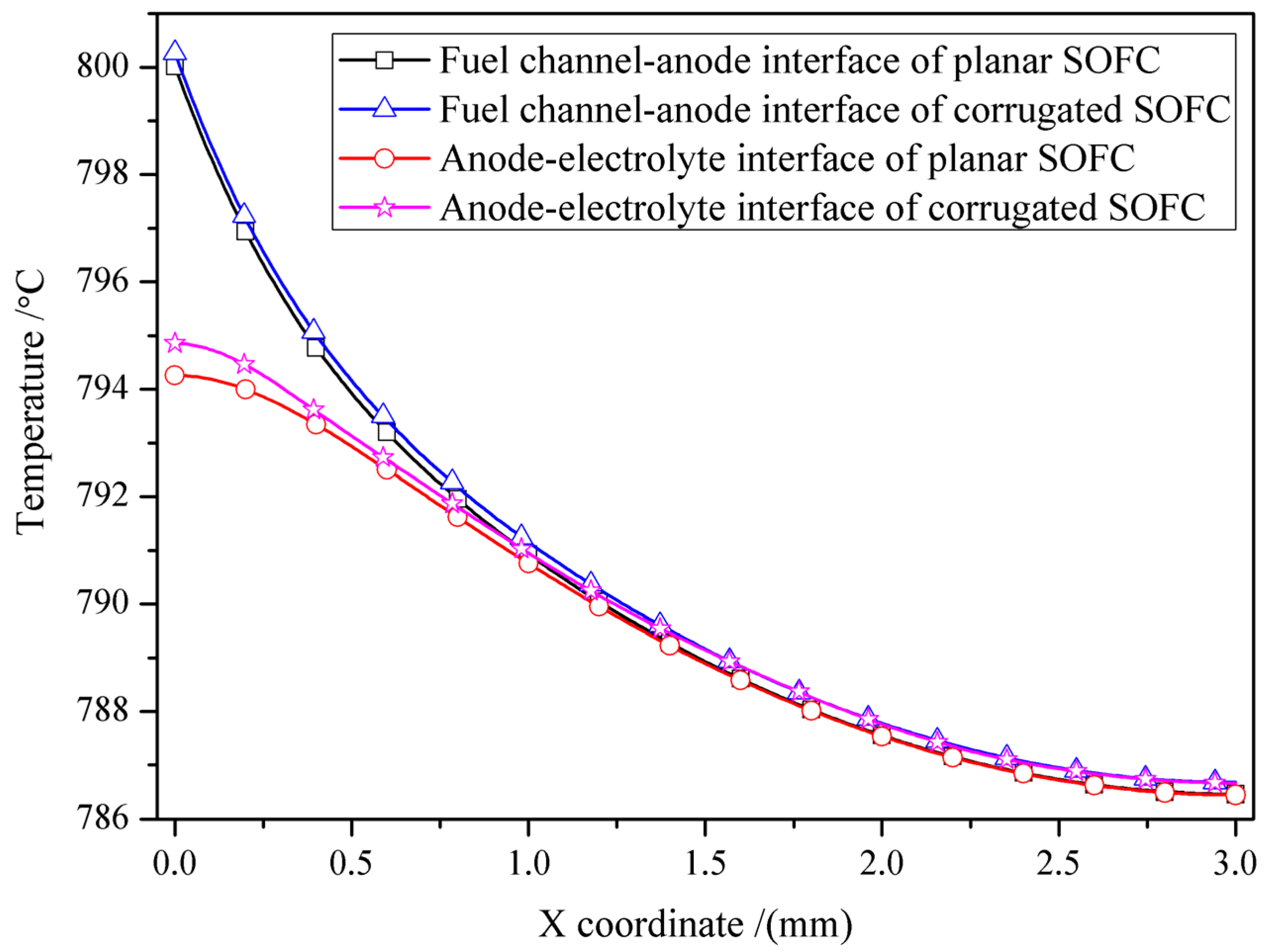
3.1. Influence of SOFC Interface Morphology on Temperature Distribution

The temperature distribution of SOFCs with different interface morphologies under the heat flux is shown in Figure 2. It can be seen that heat is conducted simultaneously from the inlet of the channel along the X and Y directions, and the temperature distribution of the planar and corrugated SOFCs is basically the same, as shown in Figure 2a,b. The temperature distribution of PEN structures with different interface morphologies are shown in Figure 2c,d. After a certain period of time, the temperature of the PEN structure reaches its operating temperature of 1073 K. The maximum temperature is located at the anode near the fuel channel inlet.
The temperature change at the cell interface along the width direction (x coordinate direction) of different interface morphologies is shown in Figure 3. It can be seen that the change trend of the interface temperature of the planar cell and corrugated cell is basically the same. The temperature of all interfaces decreases along the x coordinate direction. When x < 1.0 mm, the temperature of the fuel channel–anode interface is higher than that of other interfaces, especially at x = 0. Then, the temperature difference gradually decreases with the increase of x. When x > 1.0 mm, all interfaces have the same temperature. The above results show that the difference of material properties of the SOFC components does not cause the temperature gradient in the direction of cell thickness. While along the width direction of the cell, the farther away from the heat source, the slower the temperature drops.
The comparison of interfacial temperature of SOFCs with different interfacial morphologies is shown in Figure 4, taking the fuel channel–anode interface and anode–electrolyte interface as examples. It can be seen that the two interface temperatures of corrugated SOFC are slightly higher than that of planar SOFC, but the interface temperatures of two types of SOFCs decreased at the same rate. This indicates that a corrugated SOFC can bring the entire cell to operating temperature faster, considering only heat conduction. But for the temperature gradient formed by heat conduction, the two types of cells are consistent.
To sum up, the influence of interface morphology on the temperature distribution under SOFC heat flow is not very obvious. The temperature distribution of corrugated SOFC is only a little higher than that of planar SOFC, and the temperature gradient of both cells is the same.

3.2. Influence of SOFC Interface Morphology on Stress Distribution under the Inhomogeneous Temperature Field

The stress distribution of SOFCs with different interfacial morphologies under the inhomogeneous temperature field generated by Section 3.1 is studied by taking the inhomogeneous temperature field as a thermal load. Only the stress in the PEN structure is studied, which is shown in Figure 5. From the figure, it can be seen that the maximum stress of both the planar and corrugated cells, which have been marked in white circles, is located at the anode–electrolyte interface. But the difference is that the maximum stress is located near x = 0 for the planar cell, while it is located at the peak of the corrugated morphology for the corrugated cell. In addition, the maximum stress of the corrugated cell is 15% greater than that of the planar cell. Therefore, it can be concluded that the interface morphology has a significant influence on the maximum of the SOFC, including its position and value.
Furthermore, the anode–electrolyte interfacial stress of planar and corrugated SOFCs is compared in Figure 6. It can be seen that the anode–electrolyte interfacial stress of the planar SOFC reaches its maximum value near x = 0, then rapidly decreases until it remains constant when x > 1.0 mm, while the anode–electrolyte interfacial stress of the corrugated SOFC exhibits significant fluctuations, and the stress distribution is locally symmetrical about the peak and trough. For the maximum stress point of the planar SOFC, it is also a local peak stress in the corrugated SOFC, but it quickly decreased. The maximum stress at the anode–electrolyte interface is located at the peak of the corrugated interface, where the stress is 1.7 times that of planar SOFC; and the minimum stress is located at the trough of the corrugated interface, where the stress is 0.7 times that of the planar SOFC. In conclusion, if the initial crack is located at the boundary of the cell, it can also easily lead to delamination, while if the initial crack is located at the boundary or trough of the interface of the corrugated SOFC, it can better ensure the integrity of the cell than the planar SOFC [15].

3.3. Contribution of Temperature Gradient to Stress Distribution of SOFC with Different Interface Morphology

In order to identify the contribution of the temperature gradient caused by the heat conduction process to the thermal stress distribution of SOFC, the stress distribution of SOFCs with different interface morphologies under homogeneous and inhomogeneous temperature fields is compared, as shown in Figure 7 and Figure 8. Under the homogeneous temperature field, all parts of the SOFC are subjected to a thermal load of 1073 K. For the planar SOFC, the stress distribution under homogeneous and inhomogeneous temperature fields is similar, and the positions of the maximum values are also close, both located near the boundary of the free end of the cell, as shown in points A and A′ marked in Figure 7. The maximum stress of the planar SOFC under the inhomogeneous temperature field is 192.77 MPa, which is about 5% greater than that under the homogeneous temperature field. Meanwhile, for the corrugated SOFC, it can be seen that the maximum stress is 223.07 MPa and located at the peak of the anode–electrolyte interface for the cell under the homogeneous temperature field, and is 221.18 MPa under the inhomogeneous temperature field, as shown in points B and B′ marked in Figure 8.
From the above analysis results, it can be seen that ignoring the temperature gradient caused by heat conduction will underestimate the thermal stress of the planar SOFC, but it does not affect the overall distribution of thermal stress. And the temperature gradient contributes about 5% of the thermal stress for the cell. However, for the corrugated SOFC, the thermal stress of the cell will be overestimated, and from a quantitative perspective, the temperature gradient contributes only about 1% of the thermal stress for the corrugated SOFC. Therefore, the inhomogeneous temperature field caused by gas flow has a smaller impact on the corrugated SOFC compared with the planar SOFC. In addition, if the calculation is simplified using a homogeneous temperature field, the stress of the corrugated SOFC tends to be conservative.

4. Conclusions

The thermo-mechanical model has been proposed in the present work to investigate the heat conduction process and thermal stress distribution of SOFCs with different interface morphologies including the planar cell and corrugated cell. The inhomogeneous temperature field caused by gas flow is used as the thermal load to study the thermal stress distribution of the SOFC. The influence of interface morphology on the temperature distribution, stress distribution and the contribution of temperature gradient to stress distribution have been investigated. The following conclusions have been drawn from this study:
(1)
The influence of interface morphology on the temperature distribution of SOFCs under heat flow is not very obvious. The overall temperature of the corrugated cell is slightly higher than that of the planar cell.
(2)
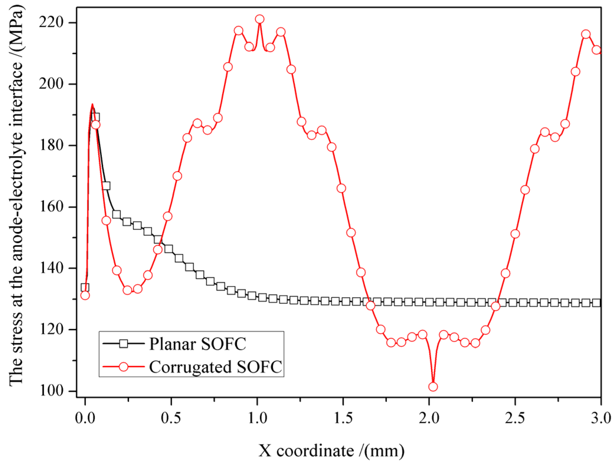
The influence of interface morphology on the stress distribution of SOFCs under the inhomogeneous temperature field is significant, including the extreme values of the cells and their locations. Compared to the planar SOFC, the corrugated SOFC has a higher maximum stress and a lower minimum stress, and more pronounced stress fluctuations. Because high stress can promote crack propagation, while low stress can restrain crack propagation, whether the interface morphology can enhance the stability of the cell is related to the position of the initial crack.
(3)
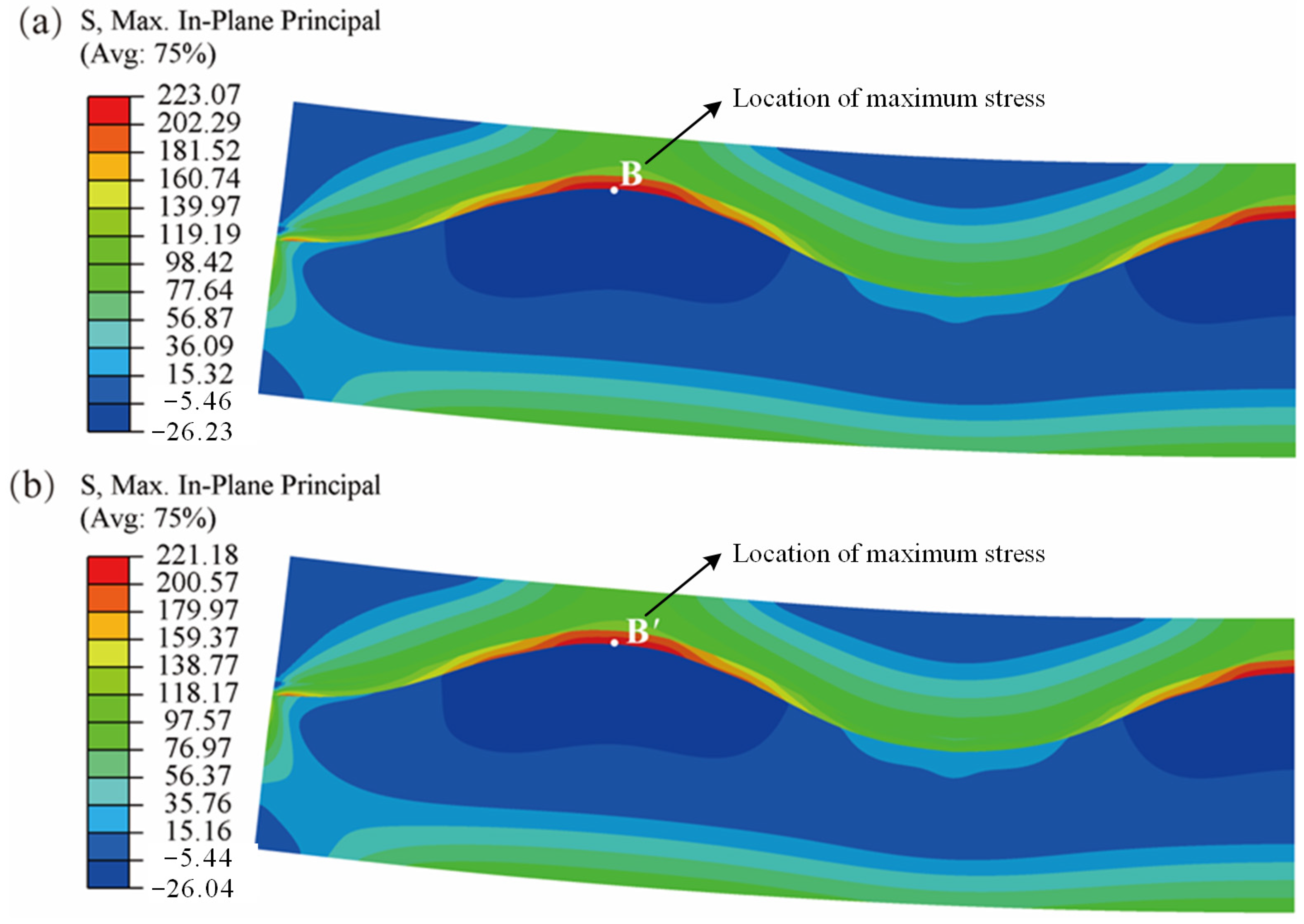
The contribution of the inhomogeneous temperature field to the planar SOFC is 5%, while the contribution to the corrugated SOFC is only 1%. And compared with the homogeneous temperature field, the inhomogeneous temperature field increases the stress of planar SOFC and decreases the stress of the corrugated SOFC. Therefore, ignoring the temperature gradient caused by heat conduction will underestimate the thermal stress of the planar SOFC, while it will overestimate for the corrugated SOFC. And if the calculation is simplified using a homogeneous temperature field, the stress of the corrugated SOFC tends to be conservative.

Author Contributions

Conceptualization, J.X., J.L. and W.H.; methodology, J.X., J.L. and W.H.; software, J.X. and W.H.; validation, J.X., J.L., W.H. and F.W.; formal analysis, W.H.; investigation, J.X., J.L., W.H. and F.W.; writing—original draft preparation, J.X. and W.H.; writing—review and editing, J.L. and F.W.; visualization, J.X. and W.H. All authors have read and agreed to the published version of the manuscript.

Funding

This research was funded by National Natural Science Foundation of China, grant numbers 12102399 and 12202407, Fundamental Research Program of Shanxi Province, grant numbers 20210302124383 and 20210302124263, and Scientific and Technological Innovation Programs of Higher Education Institutions in Shanxi, grant number 2020L0323.

Data Availability Statement

The reported data are available by reasonable request from the corresponding authors.

Acknowledgments

Authors would like to gratefully acknowledge the funding support.

Conflicts of Interest

The authors declare no conflict of interest.

References

  1. Yusaf, T.; Faisal Mahamude, A.S.; Kadirgama, K.; Ramasamy, D.; Farhana, K.; Dhahad, H.A.; Talib, A.B.D.R.A. Sustainable hydrogen energy in aviation-A narrative review. Int. J. Hydrogen Energy 2023, in press. [Google Scholar] [CrossRef]
  2. Arsad, A.Z.; Hannan, M.A.; Al-Shetwi, A.Q.; Mansur, M.; Muttaqi, K.M.; Dong, Z.Y.; Blaabjerg, F. Hydrogen energy storage integrated hybrid renewable energy systems: A review analysis for future research directions. Int. J. Hydrogen Energy 2022, 47, 17285–17312. [Google Scholar]
  3. Xie, J.M.; Wei, X.Y.; Bo, X.Q.; Zhang, P.; Chen, P.Y.; Hao, W.Q.; Yuan, M.N. State of charge estimation of lithium-ion battery based on extended Kalman filter algorithm. Front. Energy Res. 2023, 11, 1180881. [Google Scholar]
  4. Hao, W.Q.; Xie, J.M. Reducing diffusion-induced stress of bilayer electrode system by introducing pre-strain in lithium-ion battery. J. Electrochem. Energy Convers. Storage 2021, 18, 20909. [Google Scholar]
  5. Zeng, Z.Z.; Qian, Y.P.; Zhang, Y.J.; Hao, C.K.; Dan, D.; Zhuge, W.L. A review of heat transfer and thermal management methods for temperature gradient reduction in solid oxide fuel cell (SOFC) stacks. Appl. Energy 2020, 280, 115899. [Google Scholar]
  6. Xie, J.M.; Hao, W.Q.; Wang, F.H. Parametric study on interfacial crack propagation in solid oxide fuel cell based on electrode material. Int. J. Hydrogen Energy 2022, 47, 7975–7989. [Google Scholar]
  7. Liso, V.; Olesen, A.C.; Nielsen, M.P.; Kær, S.K. Performance comparison between partial oxidation and methane steam reforming processes for solid oxide fuel cell (SOFC) micro combined heat and power (CHP) system. Energy 2011, 36, 4216–4226. [Google Scholar]
  8. Rokni, M. Thermodynamic analysis of SOFC (solid oxide fuel cell)-Stirling hybrid plants using alternative fuels. Energy 2013, 61, 87–97. [Google Scholar] [CrossRef]
  9. Komatsu, Y.; Kimijima, S.; Szmyd, J.S. Performance analysis for the part-load operation of a solid oxide fuel cell-micro gas turbine hybrid system. Energy 2010, 35, 982–988. [Google Scholar] [CrossRef]
  10. Dunbar, W.R.; Lior, N.; Gaggioli, R.A. Combing fuel cells with fuel fired power plants for improved exergy efficiency. Energy 1991, 16, 1259–1274. [Google Scholar] [CrossRef]
  11. Bang-Møller, C.; Rokni, M.; Elmegaard, B.; Ahrenfeldt, J.; Henriksen, U.B. Decentralized combined heat and power production by two-stage biomass gasification and solid oxide fuel cells. Energy 2013, 58, 527–537. [Google Scholar]
  12. Zitouni, B.; Moussa, H.B.; Oulmi, K.; Saighi, S.; Chetehouna, K. Temperature field, H2 and H2O mass transfer in SOFC single cell: Electrode and electrolyte thickness effects. Int. J. Hydrogen Energy 2009, 34, 5032–5039. [Google Scholar] [CrossRef]
  13. Deng, Z.H.; Cao, H.L.; Li, X.; Jiang, J.H.; Yang, J.; Qin, Y. Generalized predictive control for fractional order dynamic model of solid oxide fuel cell output power. J. Power Sources 2010, 195, 8097–8103. [Google Scholar] [CrossRef]
  14. Zhang, L.; Li, X.; Jiang, J.H.; Li, S.H.; Yang, J.; Li, J. Dynamic modeling and analysis of a 5-kW solid oxide fuel cell system from the perspectives of cooperative control of thermal safety and high efficiency. Int. J. Hydrogen Energy 2015, 40, 456–476. [Google Scholar] [CrossRef]
  15. Xie, J.M.; Hao, W.Q.; Wang, F.H. Crack propagation of planar and corrugated solid oxide fuel cells during cooling process. Int. J. Energy Res. 2019, 43, 3020–3027. [Google Scholar] [CrossRef]
  16. Biswas, S.; Nithyanantham, T.; Thangavel, S.N.; Bandopadhyay, S. High-temperature mechanical properties of reduced NiO-8YSZ anode-supported bi-layer SOFC structures in ambient air and reducing environments. Ceram. Int. 2013, 39, 3103–3111. [Google Scholar]
  17. Ivers-Tiffee, E.; Weber, Q.; Herbstritt, D. Materials and technologies for SOFC-components. J. Eur. Ceram. Soc. 2001, 21, 1805–1811. [Google Scholar] [CrossRef]
  18. Gazzarri, J.I.; Kesler, O. Short-stack modeling of degradation in solid oxide fuel cells: Part I. Contact degradation. J. Power Sources 2008, 176, 138–154. [Google Scholar] [CrossRef]
  19. Gazzarri, J.I.; Kesler, O. Non-destructive delamination detection in solid oxide fuel cells. J. Power Sources 2007, 167, 430–441. [Google Scholar] [CrossRef]
  20. Park, K.; Yu, S.; Bae, J.; Kim, H.; Ko, Y. Fast performance degradation of SOFC caused by cathode delamination in long-term testing. Int. J. Hydrogen Energy 2010, 35, 8670–8677. [Google Scholar] [CrossRef]
  21. LeMasters, J. Thermal Stress Analysis of LCA-Based Solid Oxide Fuel Cells; Master of Science in Mechanical Engineering, Georgia Institute of Technology: Atlanta, GA, USA, 2004. [Google Scholar]
  22. Valluru, S. Steady State Thermal Stress Analyses of Two-Dimensional and Three-Dimensional Solid Oxide Fuel Cells; Master of Science in Mechanical Engineering, West Virginia University: Morgantown, WV, USA, 2005. [Google Scholar]
  23. Srikar, V.T.; Turner, K.T.; AndrewIe, T.Y.; Mark, S.S. Structural design considerations for micro machined solid oxide fuel cells. J. Power Sources 2004, 125, 62–69. [Google Scholar] [CrossRef]
  24. Tseronis, K.; Bonis, I.; Kookos, I.K.; Theodoropoulos, C. Parametric and transient analysis of non-isothermal planar solid oxide fuel cells. Int. J. Hydrogen Energy 2012, 37, 530–547. [Google Scholar] [CrossRef]
  25. Dollard, W.J. Solid oxide fuel cell developments at Westinghouse. J. Power Sources 1992, 37, 133–139. [Google Scholar] [CrossRef]
  26. Singhal, S.C. Advances in tubular solid oxide fuel cell technology. ECS PV. Jan. 1995, 1995-1, 195–207. [Google Scholar] [CrossRef]
  27. Irvine, J.T.S.; Connor, P. Solid Oxide Fuels Cells: Facts and Figures: Past Present and Future Perspectives for SOFC Technologies; Springer Science & Business Media: New York, NY, USA, 2012. [Google Scholar]
  28. Sarkar, P.; Yamarte, L.; Rho, H.; Johanson, L. Anode-supported tubular micro-solid oxide fuel cell. Int. J. Appl. Ceram. Technol. 2007, 4, 103–108. [Google Scholar] [CrossRef]
  29. Panthi, D.; Tsutsumi, A. Micro-tubular solid oxide fuel cell based on a porous yttria-stabilized zirconia support. Sci. Rep. 2014, 4, 5754. [Google Scholar] [CrossRef]
  30. Kendall, K. Progress in microtubular solid oxide fuel cells. Int. J. Appl. Ceram. Technol. 2010, 7, 1–9. [Google Scholar] [CrossRef]
  31. Funahashi, Y.; Shimamori, T.; Suzuki, T.; Fujishiro, Y.; Awano, M. Fabrication and characterization of components for cube shaped micro tubular SOFC bundle. J. Power Sources 2007, 163, 731–736. [Google Scholar] [CrossRef]
  32. Kendall, K.; Newton, J.; Kendall, M. Microtubular SOFC (mSOFC) System in Truck APU Application. ECS Trans. 2015, 68, 187–192. [Google Scholar] [CrossRef]
  33. Kendall, K.; Liang, B.; Kendall, M. Microtubular SOFC (mSOFC) system in mobile robot applications. ECS Trans. 2017, 78, 237–242. [Google Scholar] [CrossRef]
  34. Lee, S.B.; Lim, T.H.; Song, R.H.; Shin, D.R.; Dong, S.K. Development of a 700 W anode-supported micro-tubular SOFC stack for APU applications. Int. J. Hydrogen Energy 2008, 33, 2330–2336. [Google Scholar] [CrossRef]
  35. Serincan, M.F.; Pasaogullari, U.; Sammes, N.M. Computational thermal-fluid analysis of a microtubular solid oxide fuel cell. J. Electrochem. Soc. 2008, 155, B1117–B1127. [Google Scholar] [CrossRef]
  36. Jia, J.; Jiang, R.; Shen, S.; Abudula, A. Effect of operation parameters on performance of tubular solid oxide fuel cell. AIChE J. 2008, 54, 554–564. [Google Scholar] [CrossRef]
  37. Sánchez, D.; Chacartegui, R.; Muñoz, A.; Sánchez, T. Thermal and electrochemical model of internal reforming solid oxide fuel cells with tubular geometry. J. Power Sources 2006, 160, 1074–1087. [Google Scholar] [CrossRef]
  38. Yang, Y.Z.; Wang, G.L.; Zhang, H.O.; Xia, W.S. Comparison of heat and mass transfer between planar and MOLB-type SOFCs. J. Power Sources 2008, 177, 426–433. [Google Scholar] [CrossRef]
  39. Yang, Y.Z.; Wang, G.L.; Zhang, H.O.; Xia, W.S. Computational analysis of thermo-fluid and electrochemical characteristics of MOLB-type SOFC stacks. J. Power Sources 2007, 173, 233–239. [Google Scholar] [CrossRef]
  40. Hwang, J.J.; Chen, C.K.; Lai, D.Y. Detailed characteristic comparison between planar and MOLB-type SOFCs. J. Power Sources 2005, 143, 75–83. [Google Scholar] [CrossRef]
  41. Ramírez-Minguela, J.J.; Rodríguez-Muñoz, J.L.; Pérez-García, V.; Mendoza-Miranda, J.M.; Muñoz-Carpio, V.D.; Alfaro-Ayala, J.A. Solid oxide fuel cell numerical study: Modified MOLB-type and simple planar geometries with internal reforming. Electrochim. Acta 2015, 159, 149–157. [Google Scholar] [CrossRef]
  42. Konno, A.; Iwai, H.; Saito, M.; Yoshida, H. A corrugated mesoscale structure on electrode-electrolyte interface for enhancing cell performance in anode-supported SOFC. J. Power Sources 2011, 196, 7442–7449. [Google Scholar] [CrossRef]
  43. Konno, A.; Iwai, H.; Inuyama, K.; Kuroyanagi, A.; Saito, M.; Yoshida, H.; Kodani, K.; Yoshikata, K. Mesoscale-structure control at anode/electrolyte interface in solid oxide fuel cell. J. Power Sources 2011, 196, 98–109. [Google Scholar] [CrossRef]
  44. Kenjo, T.; Osawa, S.; Fujikawa, K. High temperature air cathodes containing ion conductive oxides. J. Electrochem. Soc. 1991, 138, 349–355. [Google Scholar] [CrossRef]
  45. Haanappel, V.A.C.; Mertens, J.; Rutenbeck, D.; Tropartz, C.; Herzhof, W.; Sebold, D.; Tietz, F. Optimisation of processing and microstructural parameters of LSM cathodes to improve the electrochemical performance of anode-supported SOFCs. J. Power Sources 2005, 141, 216–226. [Google Scholar] [CrossRef]
  46. Xie, J.M.; Hao, W.Q.; Wang, F.H. Interface strength analysis of the corrugated anode-electrolyte interface in solid oxide fuel cell characterized by peel force. J. Power Sources 2018, 396, 141–147. [Google Scholar] [CrossRef]
  47. Yang, C.L.; Li, W.; Zhang, S.Q.; Bi, L.; Peng, R.R.; Chen, C.S.; Liu, W. Fabrication and characterization of an anode-supported hollow fiber SOFC. J. Power Sources 2009, 187, 90–92. [Google Scholar] [CrossRef]
  48. Brahim, C.; Ringued, A.; Gourba, E.; Cassir, M.; Billard, A.; Briois, P. Electrical properties of thin bilayered YSZ/GDC SOFC electrolyte elaborated by sputtering. J. Power Sources 2006, 156, 45–49. [Google Scholar] [CrossRef]
  49. Han, M.F.; Tang, X.L.; Yin, H.Y.; Peng, S.P. Fabrication, microstructure and properties of a YSZ electrolyte for SOFCs. J. Power Sources 2007, 165, 757–763. [Google Scholar] [CrossRef]
  50. Xie, J.M.; Hao, W.Q.; Wang, F.H. The analysis of interfacial thermal stresses of solid oxide fuel cell applied for submarine power. Int. J. Energy Res. 2018, 42, 2010–2020. [Google Scholar] [CrossRef]
  51. Xie, J.M.; Hao, W.Q.; Wang, F.H. Analysis of anode functional layer for minimizing thermal stress in solid oxide fuel cell. Appl. Phys. A 2017, 123, 656. [Google Scholar] [CrossRef]
  52. Nakajo, A.; Mueller, F.; Brouwer, J.; Favrat, D. Mechanical reliability and durability of SOFC stacks. Part I: Modelling of the effect of operating conditions and design alternatives on the reliability. Int. J. Hydrogen Energy 2012, 37, 9249–9268. [Google Scholar] [CrossRef]
  53. Nakajo, A.; Mueller, F.; Brouwer, J.; Favrat, D. Mechanical reliability and durability of SOFC stacks. Part II: Modelling of mechanical failures during ageing and cycling. Int. J. Hydrogen Energy 2012, 37, 9269–9286. [Google Scholar] [CrossRef]
  54. Chatterjee, A.; Sharma, G.; Varshney, J.; Neogy, S.; Singh, R.N. Comparative study of mechanical properties of pure nanocrystalline Ni and Ni-Tf nanocomposite. Mater. Sci. Eng. A 2017, 684, 626–633. [Google Scholar] [CrossRef]
  55. Lin, Y.M.; Beale, S. Performance predictions in solid oxide fuel cells. In Proceedings of the Third International Conference on CFD in the Minerals and Process Industries CSIRO, Melbourne, VIC, Australia, 10–12 December 2003. [Google Scholar]
  56. Simulia, D.C.S. Abaqus 6.13 Help Documentation: Abaqus Analysis User’s Manual; Dassault Systems Simulia Corp: Waltham, MA, USA, 2013. [Google Scholar]
Figure 1. The structure diagrams of SOFCs with different interface morphologies: (a) planar SOFC; (b) corrugated SOFC.
Energies 16 07349 g001
Figure 2. The temperature distribution of cells with different interface morphology under the heat flux: (a) the planar SOFC; (b) the corrugated SOFC; (c) the planar PEN structure; (d) the corrugated PEN structure.
Energies 16 07349 g002
Figure 3. The temperature change at the cell interface along the width direction of different interface morphology: (a) the planar SOFC; (b) the corrugated SOFC.
Energies 16 07349 g003
Figure 4. The comparison of interface temperature between planar and corrugated SOFCs.
Energies 16 07349 g004
Figure 5. The stress distribution of SOFCs with different interface morphologies under the inhomogeneous temperature field: (a) the planar SOFC; (b) the corrugated SOFC.
Energies 16 07349 g005
Figure 6. The comparison of stress at the anode–electrolyte interface for SOFCs with different interface morphology.
Energies 16 07349 g006
Figure 7. The stress distribution of planar SOFC under different temperature field: (a) homogeneous temperature field; (b) inhomogeneous temperature field.
Energies 16 07349 g007
Figure 8. The stress distribution of corrugated SOFC under different temperature field: (a) homogeneous temperature field; (b) inhomogeneous temperature field.
Energies 16 07349 g008
Table 1. The material properties of electrodes and electrolyte in SOFC [50,51,52,53,54,55].
UnitTemperatureAnode
(Ni-YSZ)
Electrolyte
(YSZ)
Cathode
(LSM)
Thermal conductivity λW/(m·K)-6.02.76.0
Density ρkg/m3-687059006570
Specific heat cJ/(kg·K)-595606573
Elastic modulus EGPa293 K72.5196.341.3
1073 K58.1148.648.3
Poisson’s ratio μ-293 K0.360.310.33
1073 K0.360.310.33
Thermal expansion
coefficient α
×10−6/K293 K12.4110.09.8
1073 K12.6010.511.8
Disclaimer/Publisher’s Note: The statements, opinions and data contained in all publications are solely those of the individual author(s) and contributor(s) and not of MDPI and/or the editor(s). MDPI and/or the editor(s) disclaim responsibility for any injury to people or property resulting from any ideas, methods, instructions or products referred to in the content.

