Abstract
Digital twins have provided valuable information for making effective decisions to ensure high efficiency in the manufacturing process using virtual models. Consequently, AC electric motors play a pivotal role in this framework, commonly employed as the primary electric actuators within Industry 4.0. In addition, classification systems could be implemented to identify normal and abnormal operating conditions in electric machines. Moreover, the execution of such classification systems in low-cost digital embedded systems is crucial, enabling continuous monitoring of AC electric machines. Self-Organized Maps (SOMs) offer a promising solution for implementing classification systems in low-cost embedded systems due to their ability to reduce system dimensionality and visually represent the model’s features, so local digital systems can be used as classification systems. Therefore, this paper aims to investigate the utilization of SOMs for classifying operating conditions in AC electric machines. Furthermore, when integrated into an embedded system, SOMs detect abnormal conditions in AC electric machines. A trained SOM is deployed on a C2000 microcontroller to exemplify the proposed approach. It should be noted that the proposed structure can be adapted for implementation with different systems in the context of Industry 4.0.
1. Introduction
Industry 4.0 represents a significant advancement in manufacturing systems, incorporating technologies such as IoT, machine learning, digital twins, and cyber-physical systems [1,2]. This paradigm establishes a robust connection between the physical and virtual realms to enhance predictive maintenance [1], thus enabling the transition from reactive to proactive maintenance strategies. Consequently, numerous proposals have emerged focusing on developing wireless sensors [2] to facilitate the implementation of this approach. AC electric motors, particularly induction motors, have gained prominence in Industry 4.0 [3,4], finding extensive applications across different manufacturing domains. Notably, these motors exhibit lower maintenance requirements than DC motors and are generally more cost-effective [5,6]. Comprising a rotor and a stator, these motors operate without an electrical connection between the main components. The stator, which receives the electric power through its terminals, typically consists of a three-phase winding that generates a rotating magnetic field [3]. Considering the critical role of electric actuators in Industry 4.0, continuous monitoring of AC motors during their operation becomes imperative. Sometimes, these AC motors are called the horsepower of the industry. Thus, implementing classification systems is essential to effectively detect and monitor AC motors’ normal and abnormal operating conditions [7]. Table 1 shows a selection of research papers on fault detection, illustrating that fault detection has been a subject of significant interest and study within both academic and industrial sectors.

Table 1.
Papers regarding fault detection in electric machines.
Machine learning has been used in several classification systems. However, machine learning methodologies, such as deep learning or recurrent neural networks, consume high computational resources [12,13]. Machine learning methodologies, both supervised and unsupervised, can be utilized to design such systems [14]. Yet, the dimensionality of the system and the training process could be improved in their practical implementation [15]. In this regard, Self-Organizing Maps (SOMs) have emerged as a viable alternative due to their ability to reduce system dimensionality by creating Self-Organizing Maps [16,17]. Consequently, Self-Organizing Maps (SOMs) present themselves as a compelling alternative, considering the information previously explained. The intrinsic complexity in refining the Artificial Neural Network (ANN) structure for fault detection accentuates the imperative for a methodology endowed with the capability to organize and delineate complex data intuitively. SOMs, acclaimed for their adeptness in dimensionality reduction and generating spatially organized visualizations, potentially proffer a more intuitive and streamlined data representation and comprehension modality.
Given the prevalent limitation of single fault analysis in existing studies, the ability of SOMs to cluster analogous data becomes pivotal, enabling the concurrent analysis of diverse faults. This capability broadens the analytical scope and fosters a more holistic comprehension of fault conditions and interdependencies. The influence of many variables on failure detection accentuates the need for a versatile and adaptive methodology [15,16]. SOMs, with their inherent learning and adaptative capabilities, can provide precise and reliable fault detection amidst varying conditions, mitigating the complexities introduced by disparate influencing factors. Furthermore, integrating SOMs with the non-invasive condition monitoring techniques discussed, such as those utilizing voltage, current, acoustic, angular velocity, and vibration signals, can significantly enhance the efficacy and accuracy of failure detection by effectively processing and organizing the derived data. In addition, the requirement for robust and comprehensive diagnostic methods that can operate under diverse conditions aligns well with the robustness and versatile analytical capabilities of SOMs [17]. Their resilience in handling noise and variations in data can significantly contribute to formulating robust and comprehensive diagnostic methodologies.
Thus, SOMs have been proposed as a classification system for detecting fault conditions in electrical machines. This approach is demonstrated in [18], where a strategy for condition monitoring is applied to electric motors. This strategy incorporates a multifaceted fault detection and identification methodology underpinning a feature-level fusion strategy and a hierarchical Self-Organizing Map structure. Furthermore, compelling evidence has been provided for the feasibility of fault recognition using the information acquired through measured voltage and current in electrical machines. This is achieved using Kohonen’s Self-Organizing Map (SOM), which necessitates an unsupervised learning process that discerns the relationship between the locations and their respective voltage and current characteristics [19,20]. Additionally, problems of mechanical imbalances and shaft misalignments in induction motor-driven machines are addressed in [20]. In this study, the phase current is utilized to train the SOM in a simulation environment, and then, the trained SOM is subsequently validated in an experimental context. The authors convincingly demonstrate that the proposed strategy can detect imbalance and misalignment. Several papers similarly identified broken bars in fault conditions using the SOM [21,22,23]. While the methodologies presented in [18,19,20,21,22,23] focus on specific applications of Self-Organizing Maps (SOMs) for diagnosing faults and identifying mechanical unbalances in electrical machines, the proposed paper introduces a comprehensive, adaptable, and low-cost technological strategy that could be utilized to optimize electric motor performance in smart industrial applications. This paper also explores the integration of SOMs into Industry 4.0, primarily focusing on AC electric motors and showcasing advantages, particularly when considering the insights provided by the weight maps corresponding to each feature. These maps could serve as a core supplementary tool, revealing the relationships between variables in electrical machines and explicitly representing both normal and abnormal conditions. The first-principles model might also enhance the clarity and understanding of these representations, providing a robust framework for interpreting machine states. Moreover, the SOM offers a distinct advantage by reducing the system’s dimensionality, thereby facilitating the creation of a reduced-order classification map. This simplification not only aids in more efficient data processing but also enhances the accuracy and speed of decision-making processes related to the operational states of the machines. Furthermore, the reduced-order classification map can be deployed on a low-cost microcontroller, ensuring feasible implementation. The visually rendered information from the SOM can be harnessed to discern various operational conditions, providing a cost-effective and efficient solution for monitoring and managing electrical machines. In the context of Industry 4.0, where digital twins are critical, the significance of the SOM is particularly pronounced, serving as a crucial component to augment efficiency in the manufacturing process. Using low-cost microcontrollers enables the deployment of the SOM in various electric actuators within production lines, enhancing its practicality and adaptability in contemporary industrial settings. The proposed structure, which integrates SOMs into embedded systems, offers a versatile solution adaptable to various systems within Industry 4.0, spanning different industries and applications and aiding in classifying and monitoring electric motor conditions. Moreover, this proposal could assist in fault detection and diagnosis in classifying operational states and making real-time, data-driven decisions, which are crucial for optimizing manufacturing processes, enhancing efficiency, and minimizing operational disruptions. This proposal could enable predictive maintenance, enhance operational efficiency, provide a cost-effective solution, and ensure a robust, safe, and optimized manufacturing environment for the industry. On the other hand, in the emerging landscape of industrial applications, digital twins have gained prominence, with SOM being deployed in real-time simulators. However, such sophisticated simulators can present significant cost implications [24]. Moreover, machine learning coupled with digital twins has been applied to fault detection, diagnosis, and lifetime prediction in electric machines. Consequently, there is an increasing demand for cost-effective digital systems capable of fault detection. These systems should be assembled into the digital twin topology as classifiers, providing valuable resources for industrial applications. When constructing the SOM, it is crucial to consider the first-principles model to determine the relevant variables that contribute significant information, avoiding including redundant or irrelevant variables. Integrating these classification systems into low-cost, embedded digital systems can facilitate their implementation in various stages of the production line where electric actuators are employed. Moreover, these systems can be considered as part of the virtual model integrated within the structure of a digital twin, enabling effective solutions [25].
2. Electric AC Machines and SOM
Industry 4.0 utilizes electric actuators that undergo continuous monitoring to implement predictive maintenance and enhance manufacturing process efficiency [26]. Additionally, these electric machines often incorporate controllers and power electronic components within the motor casing [27], making it appealing to include a classification system that visually represents the motor’s performance, as can be achieved using Self-Organizing Maps (SOMs) [28,29]. Employing a first principles-based model of an electric machine is valuable for determining the relevant variables to be collected for SOM generation. Including variables that do not contribute to the creation of the SOM may diminish the classification system’s effectiveness and obscure the SOM’s structure. The following set of equations presented in (1) provide the primary descriptions of an induction motor in a (d-q) framework [30,31]:
where stator voltage is ; stator and rotor current are and stator and rotor flux are , ; electromagnetic torque is ; and angular rotor speed is .
These equations (first-principles model of an induction motor) could help to define the variables for elaborating and training Self-Organizing Maps (SOMs). The SOM, initially developed by Tuevo Kohonen in 1982 [17], employs an unsupervised learning methodology and is often referred to as a feature map, as it aims to capture the salient features of the input data. Furthermore, SOMs can represent high-dimensional data in a lower-dimensional space (output nodes) [25]. Figure 1 illustrates the fundamental topology of a SOM, wherein the input nodes are connected to all of the output nodes. The map nodes, on the other hand, remain disconnected, while the output nodes are arranged in a two-dimensional space. Each node’s position within the map can be described using (i,j) values, allowing for localization. Consequently, the node’s weight is updated based on the information received from the input [17,28,32].
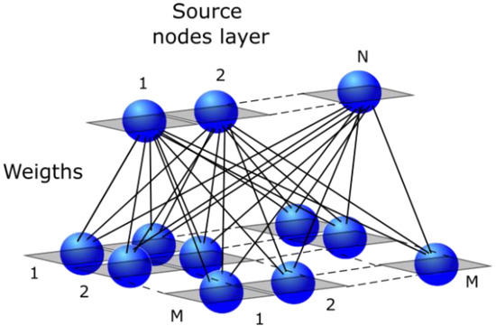
Figure 1.
(2D) Kohonen SOM.
The training algorithm for Self-Organizing Maps (SOMs) follows a fundamental structure comprising six main steps, as outlined in reference [17,32,33].
- (A)
- The initialization of weights is performed for all nodes in the SOM.
- (B)
- A set of training data from the collected data is presented to the network.
- (C)
- The nodes undergo an evaluation to determine the Best Matching Unit (BMU), representing the winning node. This evaluation involves calculating the similarity between the weights of each node and the input vector. Euclidean distance squared, as expressed in Equation (1), serves as a uniform scale for comparing each node with the input vector. In Equation (1), the Euclidean distance squared metric quantifies the dissimilarity between the weights of each node and the input vector. It provides a measure of how closely the characteristics of the input vector align with those of a particular node in the SOM. Equation (2) calculates the distance.How to calculate the BMU:
- (D)
- The calculation of the radius of the Best Matching Unit (BMU) is an integral step in the SOM training process. Initially, the radius is set to a large value and gradually decreases over each time step. This reduction follows an exponential decay pattern, as Equations (3) and (4) depict. When t (the current iteration number) is zero, the values of Equations (3) and (4) reach their maximum. As t increases, these values approach zero. Specifically, in Equation (3), the radius starts with the size of the lattice and progressively diminishes until it ultimately becomes the radius of the BMU node. Equation (3) is used to calculate the radius using exponential decay. Determination of the BMU radius reaching zero at t = tmax: These equations govern the dynamic adjustment of the BMU radius, enabling the SOM to adapt its neighborhood size throughout the training process. Initially, considering a broader radius and gradually focusing on the BMU node, the SOM achieves a refined representation of the input space.Radius of the neighborhood:Time constant:
- (E)
- The adjustment of nodes within the Best Matching Unit (BMU) radius is a crucial step in the SOM training process, aimed at aligning them more closely with the input vector. The nodes in closer proximity to the BMU undergo greater weight adjustments. Equation (5) represents the learning function, where W(t + 1) denotes a given node’s new trained weight value. This equation gradually modifies the node’s weight over time, making it more similar to the currently selected input vector, denoted as I. The disparity between the node’s weight and the input vector influences learning. Nodes that differ significantly from the current input vector experience more substantial changes, promoting greater adaptation. This difference is then scaled by the current learning rate of the SOM (6), denoted as Θ(t) (7). Learning function for weight adjustment: In Equation (5), the learning function considers the learning rate and the dissimilarity between the node’s weight and the input vector. By scaling the difference with the learning rate and the value of Θ(t), the SOM gradually converges towards an optimal representation of the input space.The new weight of a node:
- (F)
- The SOM training process involves repeating the steps described above for a specified number of epochs, denoted as n. Each epoch represents a complete iteration through the training data, allowing the SOM to continuously adjust and refine its weights based on the input vectors. During each epoch, the SOM goes through the steps of initializing weights, presenting training data, evaluating the BMU, updating the radius, adjusting the weights of nodes within the BMU radius, and iterating through the remaining epochs. This iterative process ensures that the SOM gradually adapts to the input data and improves its ability to represent the underlying patterns and structures. The SOM refines its organization by repeating the training process for multiple epochs, enhancing its ability to effectively classify and map input vectors. This paper proposes a general methodology for implementing Self-Organizing Maps (SOM) to detect normal and abnormal electric machine conditions. The methodology is delineated into several structured steps, ensuring a systematic approach to developing and deploying the SOM model for fault detection. The first step involves the definition of faults (normal and abnormal conditions). The objective here is to define and categorize the faults that will be classified, setting the scope of the research. The method employed will utilize first-principle models to identify the type of electric machine performance and establish the relations and variables essential for classifying faults according to the type of electric machine. The rationale behind this step is that it serves as a foundational layer which is pivotal for guiding subsequent feature extraction and selection processes, ensuring the model’s accuracy and efficiency in fault classification. Following the definition of faults, the next step is data collection. The objective of this phase is to accumulate pertinent data through either simulation or real experimentation. The method involves selecting appropriate sensors and acquiring data under normal and abnormal conditions when simulations or real experiments are chosen, followed by data preprocessing. The rationale is that collecting high-quality, relevant data is crucial for training and validating the model, impacting the overall reliability and accuracy of the fault detection system. Subsequently, the process of data labeling is undertaken. This step aims to assign accurate labels to the collected data to facilitate model training. The method systematically labels the data points under normal and various abnormal conditions. The foundation is that properly labeled data are essential for classification, impacting the model’s ability to generalize and accurately detect and classify unseen data. Post data labeling, the SOM model development is initiated. This phase aims to develop, train, and optimize the SOM model for fault detection. The method to be employed will initialize the model with random weights and train it using labeled data, adjusting the learning rate and neighborhood function as necessary, followed by model evaluation using a validation dataset. Developing a well-trained model is crucial for accurate and reliable normal and abnormal conditions and classification in real-world scenarios. Once the model is developed, the next step is detection (normal and abnormal). The objective here is to detect and classify different types of normal and abnormal conditions using the trained SOM model. The method involves utilizing the trained SOM to classify detected anomalies into distinct fault types. Finally, the last step is model deployment. This phase aims to integrate the trained SOM model into a microcontroller (see Figure 2).
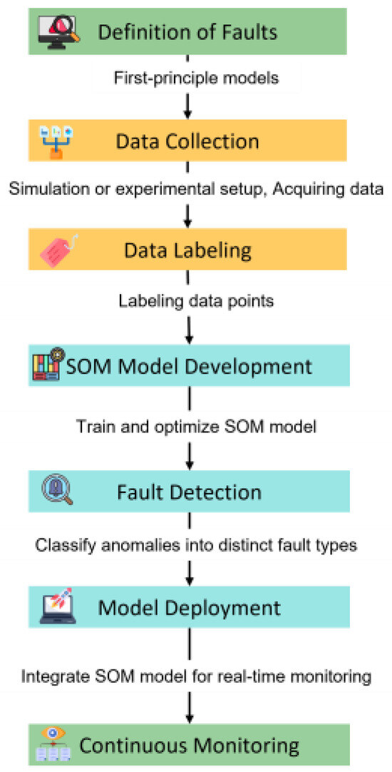 Figure 2. Sequential flow diagram of the proposed methodology.
In this sequential flow diagram, incorporating a Self-Organizing Map (SOM) with a first-principles motor model can provide an enhanced analytical framework, offering insights into system dynamics and facilitating effective abnormal detection. A first-principles model is grounded in fundamental physical laws and equations detailing the relationships between various motor variables such as voltage, current, torque, and speed. Utilizing a SOM with this model serves various purposes. It can help validate the first-principles model used via determining the areas where the model accurately or inaccurately mirrors real-world system behaviors. The insights gathered from the SOM can also contribute to refining the first-principles model by revealing previously unobserved patterns or relationships among correlated variables. The inherent relationships between different variables, described by the equations from the first-principles model, can be visualized effectively through SOMs. This visualization explores the congruence between motor data and theoretical relationships, offering insights into potential deviations due to non-modeled phenomena or faults. In the domain of fault detection, anomalies or faults in the motor will manifest as deviations from the expected behaviors outlined in the first-principles model. The SOM can identify these anomalies by recognizing input vectors that map to unexpected locations on the map.
3. Results
The first study presented in this paper illustrates the connection between the first-principles model and the Self-Organizing Maps (SOMs) to establish a clear and robust relationship. A DC motor is selected as the chosen electric machine to demonstrate this relationship effectively [34]. Subsequently, an AC induction motor is examined. The DC motor model can be decoupled into two distinct channels: one for the magnetic field and another for the armature current. Its simplicity allows for a straightforward correlation between the generated SOMs and the first-principles model. Furthermore, when AC motors are modeled within a rotating framework (field-oriented model), their representation could resemble that of a DC motor [35,36]. The representation in this rotatory framework allows a torque equation in which the current component (d) in the rotatory framework regulates the value of the flux, and the current component (q) regulates the electromagnetic torque. This representation is like Equation (7) in DC motors, so it could be possible to use the d-q currents in a rotatory framework to obtain a similar feature map as a DC motor [35]. Moreover, several other studies suggest varying methodologies for decoupling the models of induction motors [37]. On the other hand, the field-oriented model works well when the voltages and currents are balanced [38]. Thus, these maps could be different when there are fault conditions. Therefore, employing a DC motor as a representation aids to confirm the necessity of connecting the SOM implementation with the first-principles model. This connection is vital for determining the variables to be utilized and capturing the information more comprehensively within the SOMs. Simulations or real experiments can be conducted to generate data for training Self-Organizing Maps (SOMs). Given that simulations are more cost-effective and have been proven to yield high-fidelity models of electric machines, they are a preferable choice for conducting proof of concept. Thus, in this paper, simulations are used to collect data and train the SOM. After that, the SOM can be deployed in a real-time microcontroller. Additionally, simulations can effectively validate newly proposed concepts and strategies. Figure 3 displays a low-cost microcontroller, specifically the C2000 (TMS320F28379D) Launchpad, connected to a DC motor. This microcontroller can collect data coming from a DC motor [39,40]. Consequently, the microcontroller’s analog channels have the capability to receive data which can be stored to train the SOM.
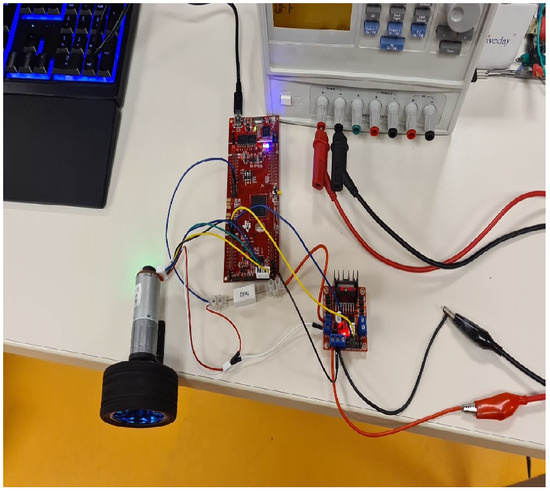
Figure 3.
C2000 (TMS320F28379D) Launchpad connected to a DC motor (collecting data).
Utilizing normalized variables from the motors is essential for training the Self-Organizing Maps (SOMs), allowing for a more standardized and consistent approach to analyzing the response of the variables. The normalization of variables is crucial as it scales the variables to a standard range, essential for comparing and analyzing data where the original scales of the variables differ. Once normalized, these variables can be employed within a Per-Unit (P.U.) system, a normalized unit system widely used to assess the performance of electric machines [41]. The Per-Unit system holds significant advantages, offering a consistent framework to assess various machines on a uniform scale, regardless of their actual physical dimensions or ratings [41]. It streamlines the analysis and design calculations pertinent to electric machines, facilitating a more effective study of the system’s behavior and performance under various conditions, encompassing normal and abnormal scenarios. In this context, the normalized variables serve as a universal metric, enabling the comparison, analysis, and evaluation of different electric machines to be more streamlined and coherent. Figure 4 illustrates the speed, current, and voltage signals from a DC motor that were collected during a normal operation using the C2000 (TMS320F28379D) Launchpad with the P.U. system.
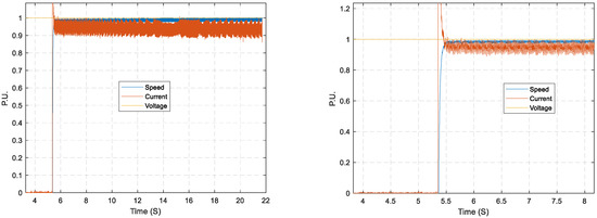
Figure 4.
DC motor speed, armature current, and armature voltage from experimental setup using the C2000 (TMS320F28379D) Launchpad.
On the other hand, MATLAB/Simulink offers specialized toolboxes designed explicitly for simulating electric machines [42]. In addition, public databases detailing electric machines’ fault conditions are available and can be instrumental data for training Self-Organizing Maps (SOMs). Several public databases provide rich datasets that illustrate the progression of typical faults such as commutator defects, winding faults, and brush wear in cost-effective DC motors under extensive monitoring, including vibration, temperature, voltage, current, and noise assessments [43,44]. These motors, known for their notably short operational life when functioning outside nominal conditions—ranging from 30 min to 6 h—are especially intriguing for testing various signal processing algorithms. They serve as practical introductions for students and researchers to signal processing, fault detection, and predictive maintenance. For instance, the Squirrel Cage Induction Motor Fault Diagnosis Dataset is a comprehensive multisensor data collection, compiled to advance research in anomaly detection, fault diagnosis, and predictive maintenance, primarily employing non-invasive methods like thermal observation or vibration measurement [44,45]. Figure 5 shows two MATLAB/Simulink block diagrams, one of a DC permanent magnet motor and the other one of an AC induction motor; these models can be used to collect data that can be used to train the SOM to detect normal and abnormal conditions.
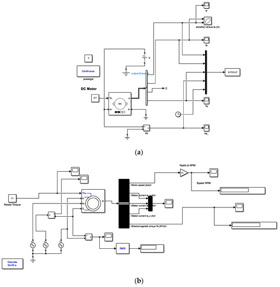
Figure 5.
Dynamic model DC motor (a) and AC motor (b) in MATLAB/Simulink.
The DC motor’s response during normal operation is illustrated in Figure 6. If normal operation is identified, it enables the potential classification of conditions that deviate from the normal performance, denoting abnormal operation.
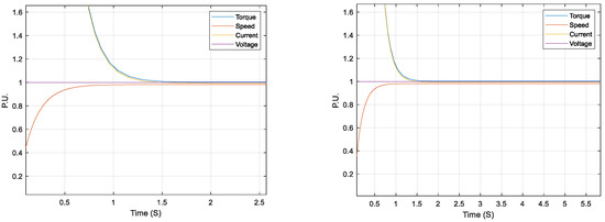
Figure 6.
This figure illustrates the responses of speed, current, and torque of a DC motor during normal operation, as modeled using MATLAB/Simulink.
The main equations governing the behavior of a DC motor are presented below [34].
In Equation (8), the electromagnetic torque generated by a DC motor is directly proportional to the armature current and the strength of the magnetic field. If the magnetic field remains constant, the electromagnetic torque becomes proportional to the armature current alone, multiplied by a constant factor, as expressed in the equation. This configuration is referred to as an armature-controlled motor.
The relationship between back electromotive force (back emf) and angular velocity of the shaft in a DC motor is shown in Equation (9), which states that the back emf in a DC motor is directly proportional to the angular rotor speed using a constant factor ().
The motor torque and back emf constant are equal in SI units. Hence, a single variable, represented by Kt and Ke, denotes the electromagnetic torque and back emf constant.
The governing Equations (10) and (11) are derived from Newton’s second law and Kirchhoff’s voltage law, incorporating the inertia (J) and the friction coefficient (b). These equations provide a foundation for analyzing the behavior and dynamics of a DC motor within the context of the first-principles model. The present study incorporates a direct current (DC) motor characterized by a permanent magnet. Determining the map’s dimensions is crucial in influencing the ultimate outcomes of the SOM training. These crucial elements are typically discerned by evaluating the input data’s attributes and understanding the expected results’ primary goals. While there are no strict protocols for deciding the number of nodes [46], a foundational principle is that the selected size should allow for the precise and unambiguous recognition of SOM structures [47]. Adhering to this principle ensures that the inherent structures within the SOM are easily perceptible and interpretable, allowing for a more instinctive interaction with and analysis of the map. Following this principle ensures that the inherent structures within the Self-Organizing Map (SOM) become readily discernible and understandable, facilitating a more intuitive engagement with and analysis of the map. In this study, a proposed topology of Self-Organizing Maps (SOMs) has been visually delineated in Figure 7. This topology comprises a 10 × 10 map and four input variables: current, voltage, rotor speed, and electromagnetic torque. On the other hand, a smaller map might not be as easily interpretable. A noteworthy correlation is evident between the weight maps of the current and the electromagnetic torque (Figure 8). This association aligns seamlessly with the results inferred from Equation (8), thereby confirming the linkage between these two variables. Similarly, the voltage and rotor speed weight maps display a significant correlation. This observation aligns with the insights from Equation (11), further consolidating a robust linkage between these two variables. The SOM’s topology, the pictorial representation of the weight maps, and the corroborative analysis drawn from the corresponding equations underscore the interconnectedness and interdependence of the input variables within the SOM framework. Figure 9 shows the weight maps when a load torque increases. The previous correlations are preserved. In the maps, the most negative connections show as black, zero connections as red, and the strongest positive connections as yellow.
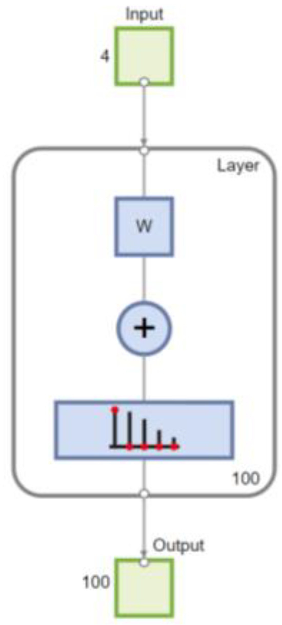
Figure 7.
SOM 10 × 10 map, four input variables: current, voltage, rotor speed, and electromagnetic torque.
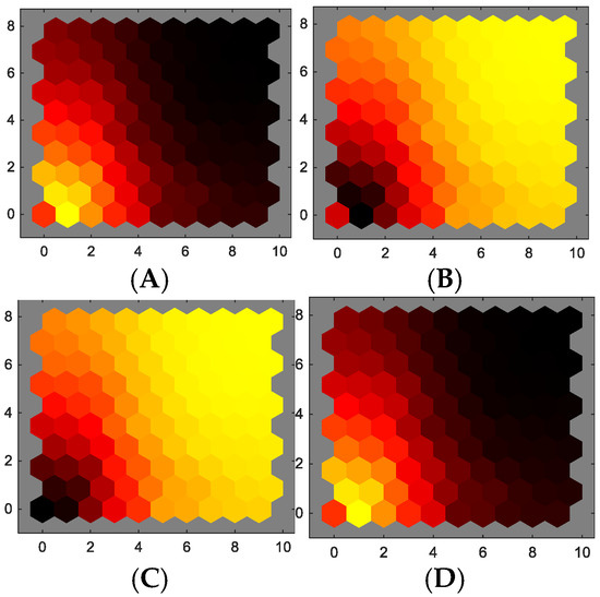
Figure 8.
Weights in features (A) current, (B) voltage, (C) rotor speed, and (D) electromagnetic torque.
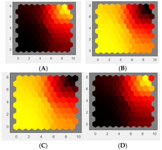
Figure 9.
Weights of features when an increment of torque load is performed, (A) current, (B) voltage, (C) rotor speed, and (D) electromagnetic torque.
The correlation between current and torque is significantly high, as validated by Equation (8), and a similar correlation is observed between voltage and rotor speed as per Equation (11). In this visual representation of weights, it is essential to highlight the role of the first-principles model. This model contributes to the dimensionality reduction of the SOM, as it aids in identifying variables with a low contribution to the study. Consequently, this identification allows the SOM to be represented with fewer nodes. Furthermore, it is important to note that collecting all potential variables could be cost-prohibitive. As for the alternating current (AC) machine, namely the induction motor, the rated performance of the induction motor, as illustrated through simulation using P.U., is depicted in Figure 10. For this evaluation, a 10 × 10 output nodes map was used (Figure 11). The features chosen for constructing the SOM include rotor speed, phase currents for stator a, b, and c, and electromagnetic torque.
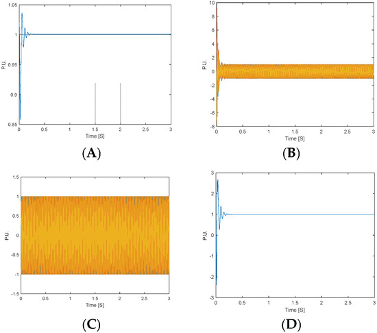
Figure 10.
Normal operation induction motor: speed (A), phase currents (B), phase voltages (C), and torque (D).
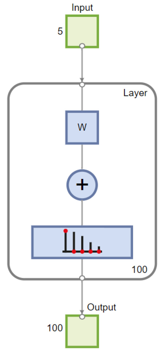
Figure 11.
SOM 10 × 10 map, four input variables: rotor speed, phase currents for stator a, b, and c, and electromagnetic torque.
Figure 12, Figure 13, Figure 14, Figure 15, Figure 16 and Figure 17 present the weights of each feature when the motor operates under various conditions: no load, rated conditions, load torque disturbances within the rated values, and an overload torque that is higher than the rated value. The no load torque and rated torque operation conditions presents a similar weight map, but the overload torque condition is an abnormal condition that presents a dissimilar weight map, so classification of this condition is feasible. For the set of the induction motor, Equation (1) shows that the electromagnetic toque depends on the stator currents, so if they have a fault condition, such as an abnormal condition like a voltage reduction of 99% in one phase (voltage sag), the weight map of torque and currents will be drastically different (see Figure 16).
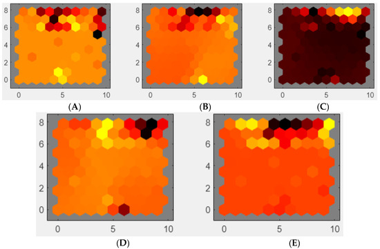
Figure 12.
Weights of features maps, four input variables: (A) rotor speed, (B–D) phase currents for stator a, b, and c, and (E) electromagnetic torque during no load torque operation.

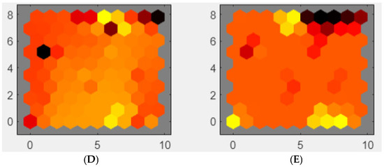
Figure 13.
Weights of features maps, four input variables: (A) rotor speed, (B–D) phase currents for stator a, b, and c, and (E) electromagnetic torque during rated load torque operation.
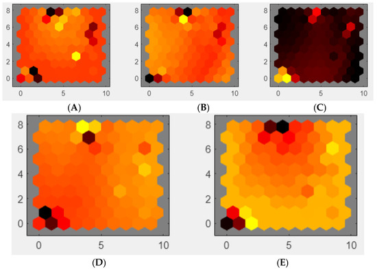
Figure 14.
Weights of features maps, four input variables: (A) rotor speed, (B–D) phase currents for stator a, b, and c, and (E) electromagnetic torque during load torque disturbances within the rated values.

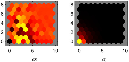
Figure 15.
Weights of features maps, four input variables: (A) rotor speed, (B–D) phase currents for stator a, b, and c, and (E) electromagnetic torque during overload torque which is higher than the rated value.
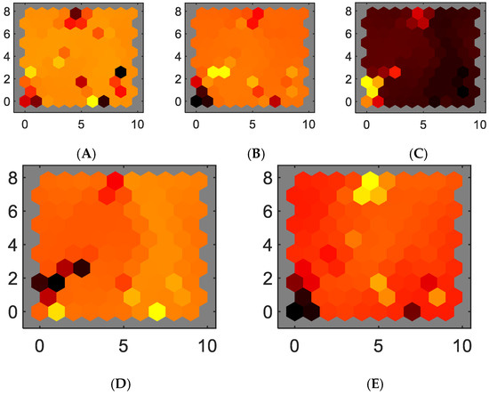
Figure 16.
Weights of features maps, four input variables: (A) rotor speed, (B–D) phase currents for stator a, b, and c, and (E) electromagnetic torque during an abnormal condition—a voltage reduction of 99% in one phase (voltage sag).
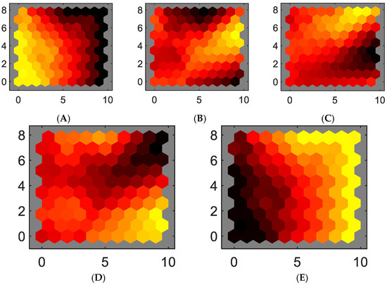
Figure 17.
Weights of features maps, four input variables: (A) rotor speed, (B–D) phase currents for stator a, b, and c, and (E) electromagnetic torque during a normal and abnormal conditions.
The weight maps illustrate the drastic changes in feature representation under abnormal conditions, such as during an overload or voltage sag. Moreover, the first-principles model offers essential insights regarding the variables that require sensing and the anticipated relationships between them. Thus, a voltage sag impacts the current and torque in a significant manner according to Equation (1), and this can be visually represented using the weight maps. Therefore, the correlations between different weight maps are more easily discernible when the first-principles model is employed. Training a Self-Organizing Map (SOM) under these conditions effectively detects normal and abnormal states. Notably, electric motors often operate within a particular zone wherein the efficiency is at its peak so abnormal conditions must be detected. Thus, these weight maps could be utilized as a tool to detect instances of high efficiency when the motor works close to the rated load torque and speed. It is feasible to train a SOM during normal and abnormal conditions so the generated map can be used to detect abnormal conditions. The detailed weight maps and the trained SOM that include these normal and abnormal conditions are presented in Figure 17 and Figure 18. Figure 18 depicts the SOM layer, where neurons are represented as gray-blue patches, accompanied by red lines indicating their direct neighbors. The neighboring patches are color-coded, ranging from black to yellow, to visually indicate the proximity of each neuron’s weight vector to its neighboring neurons. Moreover, Figure 11 displays the SOM layer, with each neuron denoting the number of input vectors it classifies. The magnitude of the colored patch represents the relative quantity of vectors assigned to each neuron.
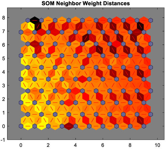
Figure 18.
SOM layer 10 × 10, neurons are gray-blue patches, and their direct neighbors are with red lines.
As a result, in an AC induction motor, the interrelation between the current, torque, and speed is pivotal in understanding the motor’s operational dynamics. Under standard operational circumstances, the current that the motor draws is generally proportional to the torque. This proportionality implies that as the load on the motor increases, the current drawn by the motor also escalates correspondingly. The operational speed of the induction motor is inherently dependent on two primary factors: the frequency of the alternating current (AC) supply and the number of poles integrated within the motor. The presence of slip, a measure of the difference between the synchronous and rotor speeds, results in the rotor trailing behind the synchronous speed. This phenomenon is crucial in analyzing the variations in motor speed due to alterations in load conditions. The foundational methodologies employed remain consistent when leveraging Self-Organizing Maps (SOM) to study AC induction motors. However, the features defined in the model and the relationships between these features exhibit distinct characteristics. Within the SOM map, regions representing high slip and torque values are visually identifiable and exhibit a direct proportionality, mirroring their theoretical interrelation. This visual representation facilitates an intuitive understanding of the inherent relationships within the motor’s operational parameters. Similarly, regions on the SOM map that depict high current values typically correlate with high torque values, reflecting their direct proportionality under diverse load conditions. This correlation is particularly significant in analyzing the motor’s response to varying operational demands. Regions on the SOM map representing high slip usually correlate with regions depicting lower rotor speeds, providing valuable insight into the motor’s operational dynamics and enabling an analysis of speed variations resulting from load alterations. The SOM is instrumental in detecting anomalies and deviations from the normal operational states of the motor. Different regions on the SOM indicate these anomalies, serving as a robust tool for fault detection and validation of theoretical models. The process of anomaly detection using the Best Matching Unit (BMU) in a SOM is meticulous. It evaluates whether the BMU or its associated values significantly deviate from the established normal conditions. To facilitate this, the SOM is initially trained under the normal operating conditions of the motor, establishing a baseline representation of the motor’s standard operational states. Each neuron’s weight vector within the SOM represents a specific normal motor condition. Once this baseline is established, incoming data are juxtaposed with the map to discern any significant deviations from the learned patterns, signaling potential abnormal conditions in the motor’s operation. By correlating the identified anomalies with the specific conditions of the motor, a comprehensive assessment can be made regarding whether the anomaly is indicative of a fault, wear, or another abnormal condition in the motor. This correlation aids in the precise diagnosis of the type of abnormal condition and its possible causes, providing insights into the progression of the condition and facilitating proactive maintenance planning and anomaly diagnosis. In this study, the trained Self-Organizing Map (SOM) has been evaluated as a proof of concept, utilizing a low-cost microcontroller, specifically, the C2000 (TMS320F28379D) Launchpad [39,40]. Table 2 shows a selection of real-time microcontrollers along with one multicore processor, outlining their principal characteristics and categorizing their respective costs. In these microcontrollers, it is feasible to implement a Self-Organizing Map (SOM). Subsequent studies could then evaluate the performance of the SOM across different microcontroller architectures.

Table 2.
Microcontrollers and one multicore processor.
The training and deployment of the SOM were conducted via MATLAB/Simulink, using an execution time of 0.001 s [53,54]. Figure 19 illustrates the microcontroller and the Simulink front panels. This front panel allows for a visual representation of the SOM. MATLAB/Simulink, a graphical programming environment, interacts with the Target Language Compiler (TLC) file in a specific way, as illustrated in the following pseudocode. The TLC file is a vital component used by the Simulink Coder throughout the code generation process [55]. The TLC file enables the transformation of high-level models in Simulink to source code suitable for specific target hardware or software environments. The provided pseudocode assists in configuring and customizing code generation for diverse targets, including the C2000 microcontroller and various software environments, ensuring optimal translation of model semantics and facilitating efficient, target-appropriate code output. This customization becomes paramount in tailoring the generated code to adhere to specifications, constraints, and performance requirements pertinent to different platforms and operational contexts.
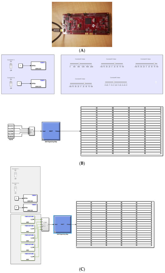
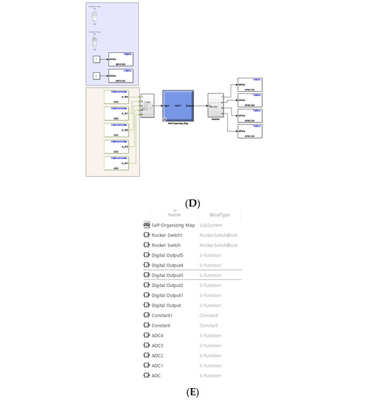
Figure 19.
MATLAB/Simulink frontal panels for implementing the SOM: Launchpad of Texas Instruments C2000 (A), Simulink frontal panel using inputs in the frontal panel and the map (B), Simulink frontal panel using analog inputs in the frontal panel and the map (C), and Simulink block types (E).
Real-Time Pseudocode Generation in MATLAB/Simulink
- 1.
- Initialize System-Specific Variables and SettingsSET TargetType TO “RT”SET Language TO “C”INCLUDE “codegenentry.tlc”
- 2.
- Define Real-Time Workshop OptionsDEFINE rtwoptions WITH PROPERTIES SUCH AS PromptMessages, UserInputType, DefaultValues, TLCVariables, MakeVariables, Tooltips, CallbackFunctions
- 3.
- Configure Option ParametersFOR EACH option IN rtwoptions:SET respective properties ACCORDING TO predefined parameters
- 4.
- Configure Code Generation SettingsSET BuildDirSuffix TO “_grt_rtw”
- 5.
- Define Target-Specific Components and ConfigurationsDEFINE target-specific components, classes, AND configurations WITH PARAMETERS SUCH AS targetComponentClass TO ‘Simulink.GRTTargetCC’
4. Conclusions
The weight maps corresponding to each feature hold the potential as supplementary information for determining relationships between variables in electrical machines. Notably, these maps can explicitly represent normal and abnormal conditions, with the first-principles model providing further clarity and understanding of these representations. Moreover, the Self-Organizing Map (SOM) offers the advantage of reducing the system’s dimensionality, thereby facilitating the creation of a reduced-order classification map. This map can be deployed on a low-cost microcontroller, and the visually rendered information can be harnessed to discern various operational conditions. The significance of the SOM is heightened in the context of Industry 4.0, where digital twins serve as crucial components to augment efficiency in the manufacturing process. Additionally, the utilization of low-cost microcontrollers makes it feasible to deploy the SOM in a variety of electric actuators within production lines. This practicality further underscores the relevance and adaptability of the SOM in contemporary industrial settings.
Author Contributions
Conceptualization, P.P. and B.A.; methodology, P.P., B.A., A.M. and A.S.D.; software, P.P.; validation, P.P., A.M., A.S.D. and B.A.; formal analysis, P.P. and B.A.; investigation, P.P., B.A., A.S.D. and A.M. All authors have read and agreed to the published version of the manuscript.
Funding
This research was funded by Tecnologico de Monterrey, School of Engineering and Sciences, Institute of Advanced Materials for Sustainable Manufacturing, and Massachusetts Institute of Technology.
Data Availability Statement
Data sharing not applicable to this article.
Acknowledgments
The authors would like to express their profound gratitude to Tecnologico de Monterrey and Massachusetts Institute of Technology for their invaluable support and contributions to this research. Their dedication to fostering a collaborative research environment and providing essential resources played a fundamental role in the successful completion of this study. We are also thankful to the faculty, staff, and fellow researchers from both institutions for their insights, guidance, and encouragement throughout the research process.
Conflicts of Interest
The authors declare no conflict of interest.
References
- Pereira, A.C.; Romero, F. A review of the meanings and the implications of the Industry 4.0 concept. Procedia Manuf. 2017, 13, 1206–1214. [Google Scholar] [CrossRef]
- Lasi, H.; Fettke, P.; Kemper, H.G.; Feld, T.; Hoffmann, M. Industry 4.0. Bus. Inf. Syst. Eng. 2014, 6, 239–242. [Google Scholar] [CrossRef]
- Zhou, K.; Liu, T.; Zhou, L. Industry 4.0: Towards future industrial opportunities and challenges. In Proceedings of the 2015 12th International Conference on Fuzzy Systems and Knowledge Discovery (FSKD), Zhangjiajie, China, 15–17 August 2015; IEEE: Piscataway, NJ, USA, 2015; pp. 2147–2152. [Google Scholar]
- Magadán, L.; Suárez, F.J.; Granda, J.C.; García, D.F. Low-cost real-time monitoring of electric motors for the Industry 4.0. Procedia Manuf. 2020, 42, 393–398. [Google Scholar] [CrossRef]
- Liang, X.; Ilochonwu, O. Induction motor starting in practical industrial applications. IEEE Trans. Ind. Appl. 2010, 47, 271–280. [Google Scholar] [CrossRef]
- Chapman, S.J. Electric Machinery Fundamentals; McGraw-Hill: New York, NY, USA, 2004. [Google Scholar]
- Markiewicz, M.; Wielgosz, M.; Bocheński, M.; Tabaczyński, W.; Konieczny, T.; Kowalczyk, L. Predictive maintenance of induction motors using ultra-low power wireless sensors and compressed recurrent neural networks. IEEE Access 2019, 7, 178891–178902. [Google Scholar] [CrossRef]
- Blodt, M.; Granjon, P.; Raison, B.; Regnier, J. Mechanical fault detection in induction motor drives through stator current monitoring-theory and application examples. In Fault Detection; IntechOpen: London, UK, 2010. [Google Scholar]
- Zhu, J.; Ertugrul, N.; Soong, W.L. Detection and remediation of switch faults on a fault tolerant permanent magnet motor drive with redundancy. In Proceedings of the 2007 2nd IEEE Conference on Industrial Electronics and Applications, Harbin, China, 23–25 May 2007; IEEE: Piscataway, NJ, USA, 2007; pp. 96–101. [Google Scholar]
- Abusaad, S.; Benghozzi, A.; Shao, Y.M.; Gu, F.S.; Ball, A. Utilizing data from a sensorless AC variable speed drive for detecting mechanical misalignments. Key Eng. Mater. 2013, 569, 465–472. [Google Scholar] [CrossRef]
- Chouhan, A.; Gangsar, P.; Porwal, R.; Mechefske, C.K. Artificial neural network based fault diagnostics for three phase induction motors under similar operating conditions. Vibroengineering Procedia 2020, 30, 55–60. [Google Scholar] [CrossRef][Green Version]
- Mathew, A.; Amudha, P.; Sivakumari, S. Deep learning techniques: An overview. In Advanced Machine Learning Technologies and Applications: Proceedings of AMLTA 2020; Springer: Singapore, 2021; pp. 599–608. [Google Scholar]
- Salehinejad, H.; Sankar, S.; Barfett, J.; Colak, E.; Valaee, S. Recent advances in recurrent neural networks. arXiv 2017, arXiv:1801.01078. [Google Scholar]
- Hopgood, A.A. Intelligent Systems for Engineers and Scientists: A Practical Guide to Artificial Intelligence; CRC Press: Boca Raton, FL, USA, 2021. [Google Scholar]
- Sorzano, C.O.S.; Vargas, J.; Montano, A.P. A survey of dimensionality reduction techniques. arXiv 2014, arXiv:1403.2877. [Google Scholar]
- Oja, E.; Kaski, S. (Eds.) Kohonen Maps; Elsevier: Amsterdam, The Netherlands, 1999. [Google Scholar]
- Guthikonda, S.M. Kohonen Self-Organizing Maps; Wittenberg University: Springfield, OH, USA, 2005. [Google Scholar]
- Saucedo-Dorantes, J.J.; Delgado-Prieto, M.; Romero-Troncoso, R.D.J.; Osornio-Rios, R.A. Multiple-fault detection and identification scheme based on hierarchical self-organizing maps applied to an electric machine. Appl. Soft Comput. 2019, 81, 105497. [Google Scholar] [CrossRef]
- Kato, T.; Ueta, G. Fault Location Identification in Power Transfomer Impulse Test. IEEJ Trans. Electron. Inf. Syst. 2001, 121, 1670–1675. [Google Scholar]
- Kato, T.; Inoue, K.; Takahashi, T.; Kono, Y. Automatic Fault Diagnosis Method of Electrical Machinery and Apparatus by Using Kohonen’s Self-Organizing Map. In Proceedings of the 2007 Power Conversion Conference-Nagoya, Nagoya, Japan, 2–5 April 2007; IEEE: Piscataway, NJ, USA, 2007; pp. 1224–1229. [Google Scholar]
- Bossio, J.M.; De Angelo, C.H.; Bossio, G.R.; García, G.O. Fault diagnosis on induction motors using Self-Organizing Maps. In Proceedings of the 2010 9th IEEE/IAS International Conference on Industry Applications-INDUSCON 2010, Sao Paulo, Brazil, 8–10 November 2010; IEEE: Piscataway, NJ, USA, 2010; pp. 1–6. [Google Scholar]
- Khalfaoui, N.; Salhi, M.S.; Amiri, H. The SOM tool in mechanical fault detection over an electric asynchronous drive. In Proceedings of the 2016 4th International Conference on Control Engineering & Information Technology (CEIT), Hammamet, Tunisia, 16–18 December 2016; IEEE: Piscataway, NJ, USA, 2016; pp. 1–6. [Google Scholar]
- Sid, O.; Menaa, M.; Hamdani, S.; Touhami, O.; Ibtiouen, R. Self-organizing map approach for classification of electricals rotor faults in induction motors. In Proceedings of the 2011 2nd International Conference on Electric Power and Energy Conversion Systems (EPECS), Sharjah, United Arab Emirates, 15–17 November 2011; IEEE: Piscataway, NJ, USA, 2011; pp. 1–6. [Google Scholar]
- Lopez, J.R.; de Jesus Camacho, J.; Ponce, P.; MacCleery, B.; Molina, A. A Real-Time Digital Twin and Neural Net Cluster-Based Framework for Faults Identification in Power Converters of Microgrids, Self Organized Map Neural Network. Energies 2022, 15, 7306. [Google Scholar] [CrossRef]
- Herwig, C.; Pörtner, R.; Möller, J. (Eds.) Digital Twins; Springer: Berlin/Heidelberg, Germany, 2021. [Google Scholar]
- Tortorella, G.L.; Fogliatto, F.S.; Cauchick-Miguel, P.A.; Kurnia, S.; Jurburg, D. Integration of industry 4.0 technologies into total productive maintenance practices. Int. J. Prod. Econ. 2021, 240, 108224. [Google Scholar] [CrossRef]
- Nandi, S.; Toliyat, H.A.; Li, X. Condition monitoring and fault diagnosis of electrical motors—A review. IEEE Trans. Energy Convers. 2005, 20, 719–729. [Google Scholar] [CrossRef]
- Kohonen, T.; Somervuo, P. Self-organizing maps of symbol strings. Neurocomputing 1998, 21, 19–30. [Google Scholar] [CrossRef]
- Asan, U.; Ercan, S. An introduction to self-organizing maps. In Computational Intelligence Systems in Industrial Engineering: With Recent Theory and Applications; Atlantis Press: Paris, France, 2012; pp. 295–315. [Google Scholar]
- Shah, S.; Rashid, A.; Bhatti, M.K.L. Direct quadrate (dq) modeling of 3-phase induction motor using matlab/simulink. Can. J. Electr. Electron. Eng. 2012, 3, 237–243. [Google Scholar]
- Bellure, A.; Aspalli, M.S. Dynamic dq model of induction motor using simulink. Int. J. Eng. Trends Technol. 2015, 24, 252–257. [Google Scholar] [CrossRef]
- Kohonen, T.; Oja, E.; Simula, O.; Visa, A.; Kangas, J. Engineering applications of the self-organizing map. Proc. IEEE 1996, 84, 1358–1384. [Google Scholar] [CrossRef]
- Cottrell, M.; Fort, J.C.; Pagès, G. Theoretical aspects of the SOM algorithm. Neurocomputing 1998, 21, 119–138. [Google Scholar] [CrossRef]
- Maheriya, S.; Parikh, P. A review: Modelling of Brushed DC motor and Various type of control methods. J. Res. 2016, 1, 18–23. [Google Scholar]
- Bose, B.K. Power Electronics and Motor Drives: Advances and Trends; Academic Press: Cambridge, MA, USA, 2020. [Google Scholar]
- Vas, P. Electrical Machines and Drives: A Space-Vector Theory Approach; Clarendon Press: Oxford, UK, 1992; Volume 1. [Google Scholar]
- Liceaga-Castro, J.; Amezquita-Brooks, L.; Liceaga-Castro, E. Induction motor current controller for field oriented control using individual channel design. In Proceedings of the 2008 34th Annual Conference of IEEE Industrial Electronics, Orlando, FL, USA, 10–13 November 2008; IEEE: Piscataway, NJ, USA, 2008; pp. 235–240. [Google Scholar]
- Espinoza-Trejo, D.R.; Campos-Delgado, D.U.; Bossio, G.; Bárcenas, E.; Hernández-Díez, J.E.; Lugo-Cordero, L.F. Fault diagnosis scheme for open-circuit faults in field-oriented control induction motor drives. IET Power Electron. 2013, 6, 869–877. [Google Scholar] [CrossRef]
- Boutahiri, C.; Nouaiti, A.; Bouazi, A.; Hsaini, A.M. Experimental Test of a Three-Phase Inverter Using a Launchpad TMS320F28379D Card. In Proceedings of the International Conference on Electronic Engineering and Renewable Energy Systems, Saidia, Morocco, 20–22 May 2022; Springer Nature: Singapore, 2022; pp. 451–459. [Google Scholar]
- MATWORKS C2000. Available online: https://www.mathworks.com/products/ti-c2000-microcontroller.html (accessed on 9 October 2023).
- Iglesias, I.; Garcia-Tabares, L.; Tamarit, J. A dq model for the self-commutated synchronous machine considering the effects of magnetic saturation. IEEE Trans. Energy Convers. 1992, 7, 768–776. [Google Scholar] [CrossRef]
- MATHWORKS. Available online: https://www.mathworks.com/products.html (accessed on 9 October 2023).
- Reñones, A.; Galende, M. FAIR open dataset of brushed DC motor faults for testing of AI algorithms. ADCAIJ Adv. Distrib. Comput. Artif. Intell. J. 2020, 9, 83. [Google Scholar]
- Piechocki, M.; Pajchrowski, T.; Kraft, M.; Wolkiewicz, M.; Ewert, P. Unraveling Induction Motor State through Thermal Imaging and Edge Processing: A Step towards Explainable Fault Diagnosis. Eksploat. Niezawodn. Maint. Reliab. 2023, 25, 170114. [Google Scholar] [CrossRef]
- Kumar, D.; Mehran, S.; Shaikh, M.Z.; Hussain, M.; Chowdhry, B.S.; Hussain, T. Triaxial bearing vibration dataset of induction motor under varying load conditions. Data Brief 2022, 42, 108315. [Google Scholar] [CrossRef]
- Park, Y.S.; Chung, Y.J. Hazard rating of pine trees from a forest insect pest using artificial neural networks. For. Ecol. Manag. 2006, 222, 222–233. [Google Scholar] [CrossRef]
- Wilppu, E. The Visualization Capability of Self-Organizing Maps to Detect Deviations in Distribution Control; TUCS Research Group: Turku, Finland, 1997. [Google Scholar]
- C2000 Real Time Microcontroller. Available online: https://www.ti.com/microcontrollers-mcus-processors/c2000-real-time-control-mcus/overview.html (accessed on 9 October 2023).
- PIC32 MZ. Available online: https://www.microchip.com/en-us/products/microcontrollers-and-microprocessors/32-bit-mcus/pic32-32-bit-mcus/pic32mz-da (accessed on 9 October 2023).
- Cortex M4. Available online: https://developer.arm.com/Processors/Cortex-M4 (accessed on 9 October 2023).
- IMX-RT-SERIES. Available online: https://www.nxp.com/products/processors-and-microcontrollers/arm-microcontrollers/i-mx-rt-crossover-mcus:IMX-RT-SERIES (accessed on 9 October 2023).
- ZYNQ. Available online: https://www.xilinx.com/products/silicon-devices/soc/zynq-ultrascale-mpsoc.html (accessed on 9 October 2023).
- Self-Organized Maps. Available online: https://www.mathworks.com/help/deeplearning/gs/cluster-data-with-a-self-organizing-map.html (accessed on 9 October 2023).
- Tisan, A.; Cirstea, M. SOM neural network design–A new Simulink library based approach targeting FPGA implementation. Math. Comput. Simul. 2013, 91, 134–149. [Google Scholar] [CrossRef]
- Target Language Compiler. Available online: https://www.mathworks.com/help/rtw/target-language-compiler.html (accessed on 9 October 2023).
Disclaimer/Publisher’s Note: The statements, opinions and data contained in all publications are solely those of the individual author(s) and contributor(s) and not of MDPI and/or the editor(s). MDPI and/or the editor(s) disclaim responsibility for any injury to people or property resulting from any ideas, methods, instructions or products referred to in the content. |
© 2023 by the authors. Licensee MDPI, Basel, Switzerland. This article is an open access article distributed under the terms and conditions of the Creative Commons Attribution (CC BY) license (https://creativecommons.org/licenses/by/4.0/).