1. Introduction
Piston combustion engines are still willingly used in drives of machines and devices, thanks to their compact structure and flexibility with the type of fuel powering them [
1]. For environmental reasons, the users of combustion engines are forced to use non-petroleum fuels [
2]. In the field of spark-ignition piston engines, renewable fuels, such as various types of alcohol fuels, have been used to power them for many years [
3]. Gaseous fuels are also used here, e.g., hydrogen [
4]. Such engines are also willingly used for the utilization of waste fuels such as post-fermentation gases (biogas) or process fuels (coke oven gas) [
5]. Many researchers around the world are conducting intensive research on the use of carbon-free fuels to power combustion engines, the advantage of which is the lack of CO
2 emissions [
6,
7]. A carbon-free fuel capable of powering internal combustion piston engines is ammonia (NH
3). Ammonia may be a significant fuel for energy transformation in this area. Due to its relatively high energy density (13.72 MJ/m
3), this fuel can be an attractive carrier of chemical energy. Ammonia can be burned in a piston engine or used as a carrier for hydrogen obtained from its dissociation. Unfortunately, the process of ammonia dissociation into hydrogen is an expensive process; therefore, research into the fueling of piston engines with ammonia is justified. Ammonia, having no carbon in its molecular structure, is a chemical compound that does not generate greenhouse gases (CO
2) that enter the atmosphere. Ammonia is an attractive zero-emission fuel that can reduce the need for conventional hydrocarbon fuels and reduce the emissions of undesirable environmental pollutants such as carbon monoxide and dioxide, particulate matter, and unburned hydrocarbons. Ammonia, like any other fuel, also has its drawbacks: it is a gas harmful to humans and causes breathing problems. It is also a source of chemical compounds formed in exhaust gases, such as NO and NO
2, which are harmful to the natural environment. In order to reduce the negative impact of such an engine’s exhaust gases on the environment, research should be carried out on the optimization of combustion in an engine powered only with ammonia or the combustion of this fuel supported with another fuel. Ammonia, due to its properties, is a fuel with low reactivity, it is characterized by difficulty in ignition (ignition energy of approximately 8 mJ) and a low combustion speed of 0.015 m/s, and it is a difficult fuel with which to conduct a stable combustion process in an engine. For this reason, other fuels are added to improve the combustion process. A common case is the use of hydrogen as a fuel that improves the ignition process itself and improves the stability of engine operation [
8,
9,
10,
11].
Gu Xin et al. [
11] used ammonia as an additional fuel, enabling the controlled combustion of hydrogen in a spark-ignition engine. They added ammonia to hydrogen at volume ratios of 5.2%, 7.96%, and 10.68%. They confirmed that the addition of ammonia extends the combustion period in such an engine and, thus, reduces the heat release rate. There was an increase in the average indicated pressure and engine efficiency. There was no clear impact of these volume fractions of ammonia on the increase in NOx emissions. Uddeen et al. drew attention to problems with ignition and a problem with the spread of the flame front in the ammonia combustion process in a piston engine [
12]. They found that the use of multi-point ignition significantly improves combustion stability, shortens the duration of combustion in the engine cylinder, and increases engine power compared to an engine with a conventional ignition system. Flame nuclei formed at multiple ignition points resulted in higher NOx emissions in the exhaust system due to higher in-cylinder temperatures. Multipoint ignition tests have already been carried out for engines powered using conventional fuels [
13]. In an ammonia-fueled engine, this solution, despite increasing costs, seems to be justified. The problem of ammonia combustion in a piston engine due to a low combustion speed was noticed by Ma et al. [
14]. They indicated that the best way to compensate for this disadvantage of ammonia is to add fuel with high reactivity, e.g., hydrogen. The ignition delay period and combustion time are shortened, which has a positive effect on the engine’s operating parameters. Chorowski et al. drew attention to the problems of using ammonia as a fuel for road transport [
15]. The authors draw attention to the dangerous side of ammonia, which is its poisonous nature, which requires the use of systems controlling its presence, and it is necessary to control unburned ammonia that escapes from the exhaust system. Attention was also drawn to the lack of clear information on the impact of ammonia co-burned with other fuels on PM emissions. Ge et al., in their work, used a mixture of ammonia and hydrogen to power a spark-ignition piston engine [
16]. Hydrogen and ammonia, considering their properties, are extremely different fuels. Hydrogen is characterized by a high combustion speed, which brings the engine to the limit of knocking combustion, which limits the engine parameters and increases the uniqueness of the engine’s operation. Ammonia, however, causes ignition problems due to its very low combustion speed and low reactivity, but an appropriate combination of both fuels should yield satisfactory results. The authors used ammonia to modulate the combustion process by controlling the rate of flame spread. It was found that, after adding ammonia, engine knocking could be avoided, even under stoichiometric operating conditions. Mounaïm-Rousselle et al. presented the results of testing an engine powered with ammonia and hydrogen operating at partial loads [
17]. For low engine loads, satisfactory operational stability was achieved for approximately 10% of the volume fraction of hydrogen in relation to NH
3. This share of H
2 allowed for NOx reduction of nearly 40% while maintaining stable engine operation. D’Antuono et al. conducted simulation tests of the operation of a spark-ignition engine powered with a mixture of ammonia and hydrogen (85% ammonia and 15% hydrogen by volume) at various operating points [
18]. It was found that the addition of hydrogen contributed to widening the range of engine speed and load control. Ronan et al., in their work, presented the results of testing an ammonia spray stream in a constant-volume chamber in an atmosphere of different densities and temperatures; the results were compared with the parameters of ethanol and gasoline injection [
19]. The parameters of the injected fuel stream were assessed: the range of the stream, the angle of the stream in the area of the injector outlet, and the half-length of the stream. A different geometry of ammonia injection compared to the reference fuels and a greater sensitivity to changes in air density and temperature in the tested space were noted. At the injector outlet, the ammonia stream was more compact than in the cases of other fuels by about 5 deg.
A synthetic summary of the results obtained by various authors is included in
Table 1.
Table 1 displays the effects of ammonia on performance, emission, and combustion parameters.
As can be seen from the several presented selected examples of the use of ammonia to power a spark-ignition piston engine, as well as the difficulties and challenges associated with it, most of these studies have referred to the use of hydrogen as a fuel facilitating the ignition process and shortening the combustion time. In our work, we used DME as a highly reactive fuel. It seems that DME may be an additional fuel that can successfully replace hydrogen in such an application. Meng et al. proposed DME as a renewable fuel that improves the ammonia combustion process [
20]. In their model considerations, complex chemical mechanisms consisting of 1597 reactions were used, and the impact of the NH
3/DME share on the laminar combustion speed and combustion stages was assessed. An increase in DME addition caused an increase in NO emissions. It was found on the basis of theoretical research that DME can be a fuel that has a beneficial effect on the combustion control process in a spark-ignition engine.
Table 1.
Performance, emission, and combustion characteristics of ammonia.
Table 1.
Performance, emission, and combustion characteristics of ammonia.
| Ref. | Engine Type | Fueling Type | Operating Parameters | Emission |
|---|
| [8] | One-cylinder, four-stroke, water-cooled engine, constant speed of 1500 rpm | NH3 and H2 into engine manifolds (PFI), hydrogen energy share: 0%, 5%, 10%, 20%, 40%, and 60% | Equivalence ratio of 0.6–1.2, the highest IMEP and ITE were achieved at low and
moderate hydrogen ratios, and H2 improved performance and stability | Minimal values were obtained for rich mixtures with high ammonia content, and maximal values were found for an equivalence ratio of 0.8–0.9 |
| [9] | One-cylinder, SI engine with variable ignition timings (18 deg bTDC to 32 deg bTDC) and WOT,
CR changes (14–16) at 1400 rpm and 1800 rpm | NH3 and H2 (PFI) | Increasing the CR from 14 to 16 increased the brake power, brake thermal efficiency, NOx, cylinder pressure, and net heat release rate by 36.82%, 25.11%, 30.21%, 10.35%, and 9.53%, respectively | NOx increased |
| [10] | One-cylinder, four-stroke, naturally aspired, constant speed of 600 rpm | NH3 and H2 into engine manifold (PFI), H2 energetic fraction: 0, 7, 12, 23, 46, 58, and 70 | 12% H2 eliminated the instability of the ignition process, powering with ammonia alone resulted in a very high IMEP uniqueness, and the optimal H2 fraction for CR10 was 7% | With the increase in the share of H2, the NO emission increased |
| [11] | Four-cylinder, four-stroke gasoline direct injection (GDI) spark-ignition (SI) engine, 1300 rpm | H2 and NH3 fuels; ammonia via PFI; H2 direct injection; the volume fraction of ammonia was 5.2%, 7.96%, and 10.68%; under part load and stoichiometric air–fuel ratio | The addition of ammonia increased the power of the engine and reduced the ITE | Increasing the ammonia volume fraction had little effect on the NOx emissions, and the NOx emissions gradually increased with the delay in the ignition timing |
| [12] | Optical spark-ignition engine (SI), multiple-spark-ignition (four spark plugs) | Pure ammonia fueling,
three air–fuel equivalence ratios (λ) of 1.0, 1.2, and 1.4 | Single-spark-ignition resulted in lower in-cylinder pressure, a longer CD, and higher combustion instability due to the poor ammonia fuel combustion rate, and
multiple spark plugs significantly improved these parameters | Multiple ignition sites resulted in higher NOx emissions, the maximum NOx level was obtained for λ: 1.2, and reducing the ammonia fuel and increasing the excess air to λ: 1.4 dramatically reduced NOx emission, |
| [16] | One-cylinder,
3000 rpm,
CR10 | H2/NH3 mixture,
Vol. of ammonia fractions: 0, 0.1, 0.2, 0.3, 0.4, and 0.5, | An increase in the ammonia fraction reduced the flame speed, and
the maximum work output of blended ammonia/hydrogen can reach 90% of a pure gasoline SI engine under the same operating conditions | With more blends of ammonia, the NO can be partially converted to nitrogen, which
reduces the engine-out NO emissions |
| [17] | Four-cylinder, four-stroke GDI-SI EP6 PSA engine modified to become an indirect-injection, single-cylinder engine,
CR10.5 | H2/NH3 mixture, PFI,
low load | The engine stably operated with less than 10% H2 (of the total fuel volume) added to NH3;
for neat ammonia, the low load operation was difficult with
a compression ratio of 10.5, requiring a higher minimum intake pressure | The maximum value of NOx was reached in a lean air/fuel mixture, the NH3 at the exhaust increased with an equivalence ratio when the NOx decreased, and the addition of H2 to the mixture with ammonia induced an NH3 emission decrease |
| [21] | SI engine, CFR | Ammonia/hydrogen mixtures,
PFI, varying excess air,
different ammonia-to-hydrogen ratios | The fuel mixture with 10 vol.% hydrogen performed best with respect to efficiency and power; in comparison with a gasoline-fueled engine, efficiency and power increased due to the possibility of a higher compression ratio | To reduce the high NOx emissions, SCR exhaust was used |
| [22] | Four-stroke, two-cylinder SI engine of 505 cm3 | NH3/H2 mixture | The addition of hydrogen to an air–ammonia mixture improved ignition and increased the combustion velocity; the hydrogen-to-ammonia energy ratio mainly depended on the load and less on the engine speed; and the efficiency of the engine fueled with NH3/H2 was lower than that with gasoline | - |
In the available literature, it is difficult to find works dealing with the use of DME as a fuel supporting the combustion of ammonia in a SI engine; hence, this work is innovative and expands the current scope of knowledge. This paper presents the results of experimental tests performed on a spark-ignition research engine (CFR) powered with ammonia, ammonia, and DME. Ether was intended to improve the ignition initiation process and shorten the combustion time. The impact of the DME share on engine operation indicators such as IMEP (indicated mean effective pressure), ITE (indicated thermal efficiency), and SEC (specific energy consumption), as well as the heat release process, combustion stages, and the stability of the engine operation, were assessed. The parameter determining the share of co-combusted DME with NH3 was the achievement of optimal IMEP and ITE values. The tests were carried out for a compression ratio of 10 because, for lower compression ratios, it is not possible to operate an engine powered with only ammonia.
2. Materials and Methods
The tests were carried out on a single-cylinder spark-ignition research engine with a compression ratio of 10 and a constant rotational speed of 600 rpm. The assumption of the research was the application of such a fuel to power industrial engines operating at a constant rotational speed. The compression ratio of 10 was chosen based on previous studies on this engine powered with NH
3 and hydrogen fuels. The basis of the test stand was the UIT-85 research engine with a forced, open water-cooling system. The motor was braked via an asynchronous electric machine controlled with a frequency converter that gave energy to the braking resistors. The engine specifications are shown in
Table 2.
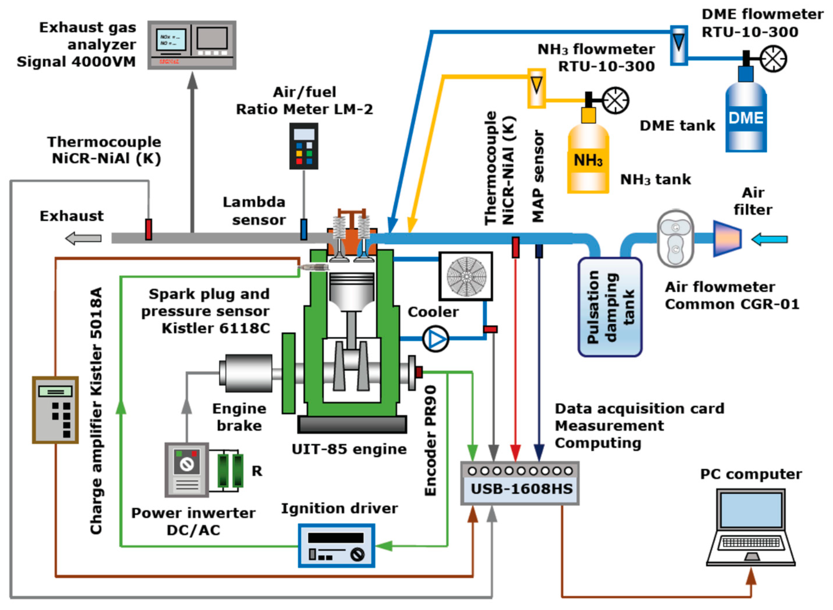
An encoder was mounted on the camshaft, serving as a digital transmitter of the signals of the instantaneous angular position of the engine shaft and the piston TDC (top dead center) marker, directed to the digital ignition controller and data acquisition card. This card also recorded the signal from the pressure sensor of the spark plug processed in the charge amplifier and amplified signals from thermocouples measuring the temperatures of exhaust gases, the fuel–air mixture, the surroundings, and the water jacket. These data were sent to a PC and analyzed and processed programmatically. Air was supplied to the engine intake manifold through a route consisting of a filter, a rotor flowmeter, and a pulsation dumping tank. Gaseous ammonia was taken from the cylinder with a pressure reducer through a flowmeter to the intake manifold, where it was mixed with gaseous DME that was also supplied from the cylinder with a pressure reducer through a second flowmeter. Both fuels were delivered to the intake manifold in gaseous form (PFI—port fuel injection). The research was conducted for the optimal CA50 angle, which required a change in the ignition timing. There was a pressure sensor in the intake manifold. A broadband lambda sensor with a measurement system was installed in the exhaust manifold, as well as an exhaust gas analyzer probe to determine NOx emissions. The diagram of the test stand is shown in
Figure 1.
The parameters of the measuring equipment and its accuracy are presented in
Table 3.
The aim of the research was to determine the impact of the addition of DME to an ammonia-gas-powered SI engine on its operation and the emission of toxic exhaust gas components (NOx). The main research included checking the impact of different percentages of DME in a constant total energy dose of fuel composed of ammonia and DME. The percentage of DME energy in the
eDME fuel was determined according to the following relationship:
where
EDME and
ENH3 represent the DME and ammonia energy in the total fuel dose per cycle.
Combustion tests in a spark-ignition engine powered with a mixture of DME and ammonia gas were carried out at a constant rotational speed of 600 rpm, with the throttle fully open and with a constant total energy fuel dose. The research included:
The indication of an engine with a compression ratio of 10 for the energy percentages of DME in the fuel: 0%, 8%, 10%, 13%, 18%, 24%, and 29%. For each of these fuel compositions, the pressure in the engine cylinder was recorded during 150 consecutive cycles of its operation, with simultaneous measurements of the intake air temperature, engine temperature, exhaust gas temperature, ammonia, DME, intake air flows, and NOx concentration in exhaust gases;
Analysis of the course of changes in cylinder pressure in subsequent cycles and the rate of heat release as a function of the fuel composition;
Analysis of changes in IMEP and ITE as a function of fuel composition;
Analysis of changes in the coefficient of variation of IMEP (COVIMEP) as a function of fuel composition;
Analysis of combustion phases divided into the initial combustion phase from ignition to CA10 and the main combustion phase from CA10 to CA90 as a function of fuel composition;
Analysis of changes in nitrogen oxides (NOx) emissions and exhaust gas temperature as a function of fuel composition.
The ignition advance angle for all DME–ammonia mixtures was 22 deg bTDC, while in the case of operation using ammonia only, due to its difficult ignition, it was 46 deg bTDC. The excess air coefficient λ was maintained in the range of 1.0–1.05. The tests were carried out at the optimal heat release angle of 50% (CA50), equal to approximately 10 deg CA after TDC. The cylinder pressure recording system used in the research also determined the instantaneous engine speed based on measuring the duration of pulses generated via the crankshaft angle marker. The recorded pressure waveforms were analyzed in real time, so it was possible to observe:
The maximum pressure and the angle of its occurrence;
The maximum speed of pressure changes and the angle of its occurrence;
The engine speed;
The unit-indicated work;
The indicated cylinder power;
A 50% heat release angle (CA50).
During measurements, the following were also displayed on an ongoing basis:
A cylinder pressure indicator chart—open and closed;
Graphs of the derivatives of pressure, temperature, and heat release and a graph of mass fraction burned as a function of the crankshaft rotation angle.
Pressure in the engine cylinder was recorded for every 1 degree of crankshaft rotation. Meanwhile, the temperatures of the intake air, engine, and exhaust gases were recorded as average values from 720 samples collected in each cycle. A 16-bit module with synchronously operating AC converters was used for signal acquisition.
The indication system also presented graphs of changes in the speed, indicated work, and indicated power in subsequent cycles and measured and recorded the temperature values for each engine cycle: the air in the intake duct, exhaust gases, and coolant. The exhaust gas analyzer allowed for the measuring and recording of the concentration of nitrogen oxide (NOx) in the engine exhaust gases.
The measurements of ammonia, DME, and air streams fed into the engine intake duct allowed the determination of the value of the excess air coefficient
λ for the DME and ammonia mixture:
where
ma denotes the air mass,
mDME represents the DME mass,
mNH3 indicates the mass of ammonia, and (
A/
F)
s represents the stoichiometric air-to-fuel ratio, which is equal to:
where (
A/
F)
s1 represents the stoichiometric air-to-fuel ratio for DME, (
A/
F)
s1 = 9, and (
A/
F)
s2 denotes the stoichiometric air-to-fuel ratio for ammonia: (
A/
F)
s2 = 6.04.
The measurements for each fuel composition were repeated three times, always after thermal stability was achieved, and their results were averaged. A detailed scope of the studies is given in
Table 4.
3. Fuel Characteristics
The fuels used in the tests were ammonia (NH
3) and dimethyl ether (DME) (
Table 5). Ammonia (NH
3) is an inorganic chemical compound of nitrogen and hydrogen. It is a colorless gas with a pungent odor. It is an extremely toxic substance and may be very hazardous to health upon direct contact. It is a carbon-free compound, contains 17.6% hydrogen, and is characterized by a relatively high energy density (13.72 MJ/m
3). The very high octane number of ammonia (about 130) makes it possible to use this gas in a spark-ignition combustion engine with a higher compression ratio. Ammonia is characterized by good anti-knock properties, so as the main fuel ingredient, it should reduce the occurrence of this unfavorable phenomenon. These features make ammonia an attractive fuel in the transport and energy sectors. One of the main disadvantages of ammonia as a fuel is its lower reactivity than conventional coal-based fuel, which complicates the combustion process and may negatively affect the emission of toxic and harmful exhaust gas components. Its relatively low calorific value (LHV = 18.8 MJ/kg), high heat of vaporization (HoE = 1370 kJ/kg), low laminar combustion speed (LFS = 0.015 m/s), high auto-ignition temperature (651 °C), and narrow flammability range (15–28) hinder the use of ammonia in piston engines [
21]. These properties create problems in effective combustion in both compression ignition and spark-ignition engines. The undoubted advantage of ammonia is its ease of storage. Ammonia can be used directly as a fuel, for example, in power turbines in thermal power plants or as a fuel in maritime transport. Ammonia can be easily transformed into hydrogen. Hydrogen, especially in the form of ammonia, is highly significant in the decarbonization process of the energy sector in many developed countries and is one of the methods to move away from fossil fuels. Ammonia can serve as a high-quality energy carrier, having a significant advantage over hydrogen. Hydrogen needs to be stored at a temperature of 20.15 K (−253 °C) as a liquid or at a pressure of about 70 MPa (700 bar) as a gas. Liquid ammonia can be stored at a reasonable temperature of 240.15 K (−33 °C) at standard pressure and 293.15 K (+20 °C) at a pressure of 0.9 MPa (9 bar). This makes storing and transporting this energy carrier much easier, cheaper, and simpler. Due to the large mass fraction of hydrogen in the NH
3 molecule, ammonia can be used as an efficient hydrogen energy carrier. Ammonia in nature is produced as a result of the microbiological decomposition of nitrogenous organic substances containing protein, while in industry, the primary raw materials used for its production are natural gas and air [
22]. Currently, efforts are being made to produce ammonia from renewable sources (RES). In this case, energy from RES is first used to produce green hydrogen (water electrolysis), which is then converted into green ammonia. Hydrogen from water electrolysis can be used to produce ammonia, and the electrolysis itself can be performed using biomass energy, wind energy, solar energy, geothermal energy, or hydroelectric energy [
23].
Dimethyl ether (DME) belongs to the organic chemical compounds from the group of ethers. It is a colorless gas with a characteristic odor and is moderately soluble in water. DME can be used as a standalone fuel in compression ignition engines or as a mixture in spark-ignition engines. DME was chosen as an assisting fuel to enhance the combustion process of NH3 in a spark-ignition engine. The main reason for selecting this fuel lies in its properties, which largely contrast with NH3, primarily the LFS value, wide flammability range in air, and ease of ignition. It plays a particularly good role as a fuel in diesel engines—its cetane number is over 55, while for diesel oil, it usually does not exceed 53. DME is the simplest ether obtained from both fossil and renewable raw materials. Dimethyl ether is usually produced via the dehydration of methanol. More environmentally friendly methods are increasingly being used, such as producing DME from syngas, a mixture of hydrogen and carbon monoxide. The synthesis of dimethyl ether is more efficient than the dehydration of methanol because it allows the production of this compound from waste or biomass, bypassing the production of methanol. Ecological DME production methods allow this gas to be classified as a renewable fuel. Dimethyl ether is produced from synthesis gas using two methods: indirect synthesis (through methanol) and direct synthesis. Dimethyl ether, through synthesis gas, can be produced from raw materials such as biogas, biomethanol, biomass, natural gas, hard coal, brown coal, oil shale, plastic waste, and municipal waste. Synthesis gas obtained from steam-reforming various raw materials and bioresources can be further utilized for the direct synthesis of dimethyl ether. If raw materials such as biomethanol, biomass, or biogas are used in DME production, the DME is formally recognized as a biofuel (BioDME). The application of BioDME in automotive transportation can reduce greenhouse gas (GHG) emissions by 92–95%. DME can be liquefied at room temperature and stored in liquid form. Dimethyl ether is characterized by a relatively low calorific value (LHV = 28.4 MJ/kg), a flash point comparable to that of diesel oil (235 °C), and a wide flammability range (3.4–27 vol.%). It burns without soot, has a low ignition temperature, and evaporates perfectly. One of the greatest advantages of DME is the lack of emission of dust pollutants, thanks to the absence of direct carbon bonding in the atomic structure, as well as the presence of oxygen in this bond (approx. 35%). Dimethyl ether (DME) may also be a potential fuel used in low-temperature fuel cells that operate below 100 °C.
4. Results and Discussion
The tests on the combustion of ammonia alone and the co-combustion of ammonia with DME were carried out for a full engine load, a constant rotational speed, and a compression ratio of 10. Due to the low value of the combustion speed of ammonia, it was examined how the addition of DME to it affects the combustion process. DME is characterized by a much higher combustion speed than ammonia and, therefore, should improve the ignition initiation process and shorten the combustion time. Ammonia is characterized by good anti-knock properties, so as the main fuel ingredient, it should reduce the occurrence of this unfavorable phenomenon. The analysis of the combustion process of both fuels was carried out based on the results of measurements of the instantaneous pressure in the engine cylinder and exhaust emissions. Heat release patterns were determined based on the pressure curves obtained. The standardized course of heat release was used to determine the characteristic stages of combustion, i.e., the ignition delay time (CA10) and combustion time (CA10-90). Ignition delay (CA10) is the period from the spark discharge at the spark plug to the point of 10% heat release. The combustion duration (CA10-90) is the period from the point of 10% heat release to the point of 90% heat release. The CA50 value defines the point of 50% heat release and is calculated from the TDC (top dead center). The tests were carried out at the optimal heat release angle of 50% (CA50) at the level of 10 ± 1 degrees CA after TDC. The ignition delay was determined in degrees CA as the angular interval from the moment of ignition to the moment of 10% heat release. The combustion time was the interval between the moment of releasing 10% of the heat and the moment of releasing 90% of the heat. Knowledge of these characteristic stages of combustion is crucial for optimal engine control.
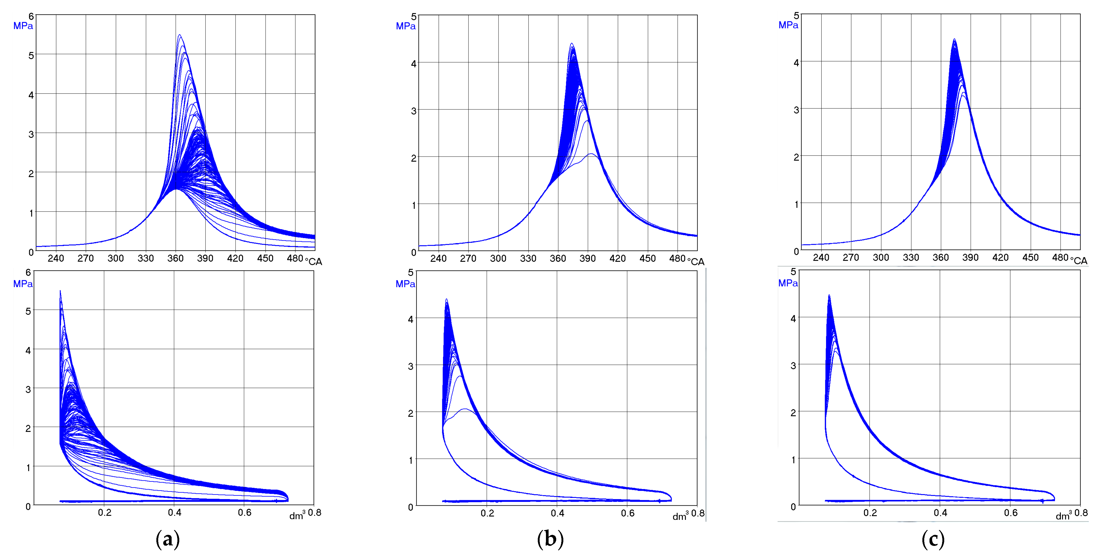
Figure 2 presents a summary of the combustion pressure and pressure rise curves for an NH
3-fueled engine with various DME additives ranging from 0% to 29% of the energy share. For a compression ratio of 10, the engine powered by NH
3 alone worked, but its operation stability was unsatisfactory (COV
IMEP = 30%). To improve the quality of engine operation and combustion stability, DME was added, and with its 8% share, a significant improvement in engine performance indicators was achieved.
The addition of 8% DME (by energy share) resulted in an increase in the average (from 150 cycles) of the maximum pressure in the engine combustion chamber of 1.35 MPa compared to the engine powered by NH
3 alone. There was also a shift of p
max towards TDC of 3.5 deg. Each research point was optimized according to the CA50 criterion. A further increase in the energy share of DME to 24% resulted in an increase in the average p
max value, which for this DME share was 17 deg aTDC and amounted to 3.97 MPa. Increasing the DME share to 28% resulted in a significant decrease in the p
max value to 3.72 MPa. Due to the p
max criterion, it can be concluded that even an 18% DME share provides the optimal pressure value. The analysis of the pressure increase (
Figure 2b) showed that the addition of DME provides the (dp/dφ) values desired in an SI engine for its proper operation. For all runs involving DME, peak values (dp/dφ)
max occurred around 10 deg aTDC and were in the range of 0.16 to 0.19 MPa/deg. Only for an engine fueled only with NH
3, the average (dp/dφ) curve was too flat, which indicates very slow combustion, which does not ensure appropriate gas-dynamic parameters for exhaust gases in the engine cylinder.
Analysis of the course of heat release in a piston engine is the basis for assessing the combustion process in the engine. The heat release rate (dq/dφ) provides information about the dynamics of the combustion process, while the integrated waveform of the heat release rate allows for the determination of characteristic stages of combustion.
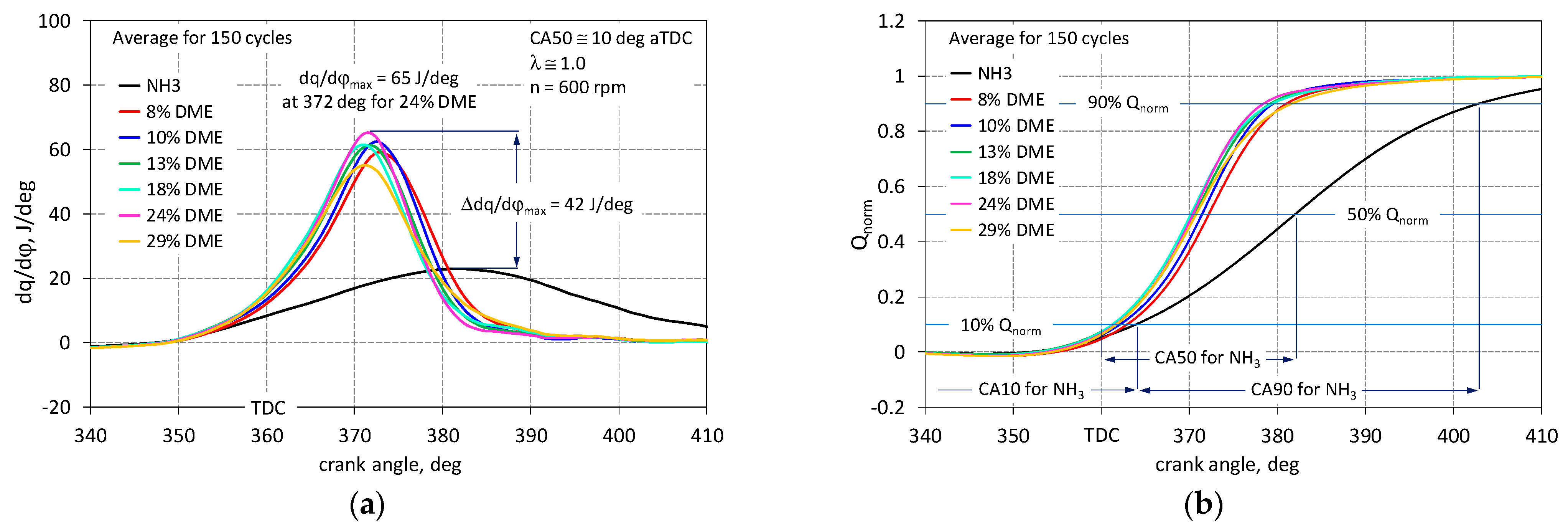
Figure 3 shows the obtained heat release waveforms.
Figure 3a shows the waveforms of the heat release rate depending on the share of DME. For an engine fueled only with NH
3, the average waveform (dq/dφ) was very flat, i.e., the maximum heat release rate was very low and amounted to 22.8 J/deg, and 22 deg aTDC was achieved. Despite the optimization of the engine operation using the CA50 criterion, satisfactory results could not be achieved for fueling with NH
3 alone due to the very high uniqueness of the cycles. For the waveform averaged from a set of 150 cycles, the CA50 value was reached at 22 degrees aTDC, i.e., too late (
Figure 3b). The addition of 8% DME resulted in a significant improvement in the heat release rate; for this share, a peak value of 58 J/deg was recorded, and the CA50 value was 12 deg, i.e., the engine operation was already close to optimal operation. For piston engines, it is assumed that CA50 within the limit of 10 deg is optimal [
28]. The maximum value (dq/dφ) of 65.2 J/deg for an angle of 12 degrees after TDC was recorded for 24% of DME. The maximum values (dq/dφ) for the engine fueled with a DME addition were in the range of 10.4 J/deg. From the Q
norm (normalized heat release) waveforms, it can be seen that the addition of DME clearly shifted the CA50 angle towards the optimal value, close to 10 deg aTDC; all obtained waveforms from 8 to 29% DME shares were focused in a narrow spread range (CA50) of 2.5 deg. The obtained Q
norm waveforms were used to determine the location and length of characteristic combustion stages.
Knowing the values of individual combustion stages provides detailed information about the dynamics of this process. This is especially important for fuels that are difficult to burn, such as ammonia. Knowing the value of the ignition delay CA10 allows for appropriate corrections in the engine control system in terms of the ignition angle. The CA50 value is used to optimize the engine’s thermal circulation, and knowledge of the CA10-90 angle provides indirect information about the engine’s efficiency.
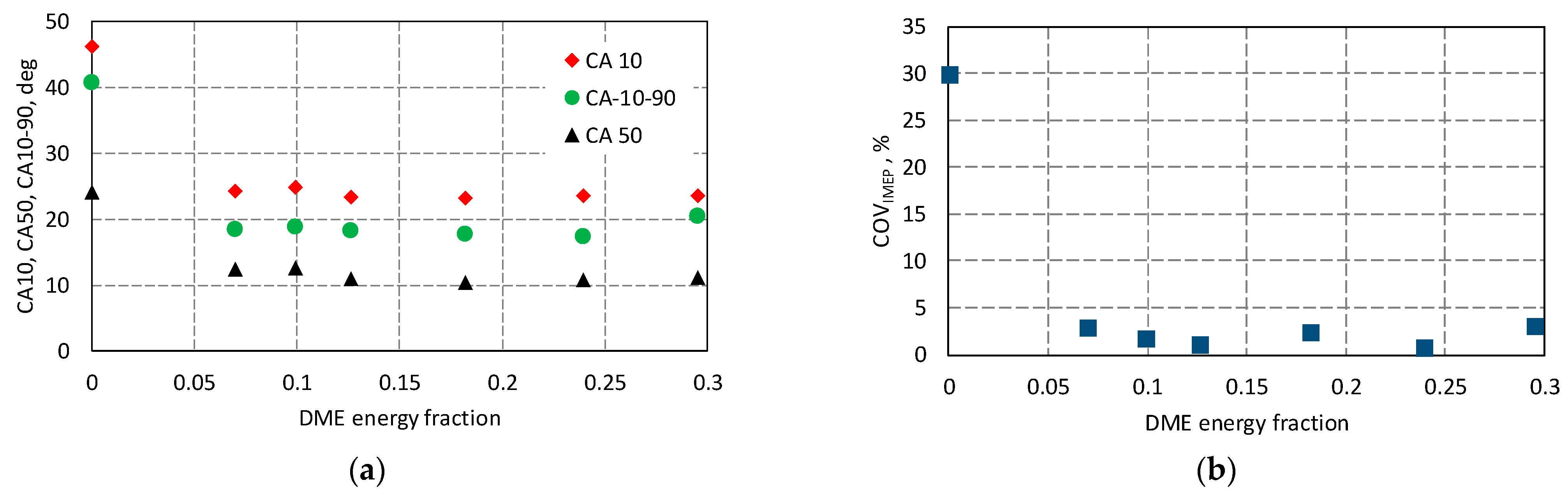
Figure 4a presents a summary of individual combustion stages for the analyzed cases of the co-combustion of DME with NH
3. For the engine fueled only with ammonia, the CA10 value was 46.2 deg, and the 8% share of DME reduced the CA10 by 22 deg to 24.2 deg.
Increasing the DME dose no longer caused such significant changes in CA10 values; for all DME shares, the CA10 value was within 1.5 deg. The lowest CA10 value of 23.1 deg was recorded for 18% DME.
When analyzing the combustion stages, it should be taken into account that the obtained values for ignition delay (CA10) and combustion time (CA10-90) were determined for the waveform averaged over 150 cycles. In the case of the high non-repeatability of the engine operation, especially when fueled only with ammonia, they do not reflect the actual fluctuations of these parameters in subsequent engine operation cycles. Therefore, the duration of CA10-90 combustion for an engine fueled only with NH
3 was as much as 41 deg. It should be noted that, for this operating point, there was very high non-repeatability of the engine operation (COV
IMEP = 30%). This was mainly due to the low LFS of ammonia, which hinders the flame front propagation, which is especially crucial in the initial phase of combustion (the ignition delay period). The low flame front speed in the initial phase of combustion, just after spark-ignition initiation, contributes to an increase in the ignition delay time. Conversely, a significant ignition delay time in piston engines results in an increase in the variability of successive engine cycles. The addition of DME to NH
3 significantly shortened the average combustion duration, setting it at approximately 18 deg. The CA50 value, according to the optimization assumptions of the engine cycle, should be 10 deg aTDC. Shortening the duration of combustion in the engine results in an increase in its efficiency (ITE) and the value of the average indicated pressure and, at the same time, a decrease in specific fuel consumption [
29,
30]. The combustion time affects the use of the energy contained in the fuel, increasing the combustion efficiency, which will also affect the exhaust gas temperature and then the exhaust emissions [
31]. The highest maximum temperature values during combustion of around 1750 K were obtained for DME contents ranging from 18–24%. Reducing the DME dosage resulted in a slowing down of the temperature increase during combustion and a decrease in its maximum value. With a DME dosage increased to 29%, the maximum temperature noticeably decreased.
When fueled with NH
3 alone, due to the high uniqueness of the engine operation, the CA50 criterion could not be met during the tests. The engine fueled with the addition of DME to NH
3 already provided the expected low operating uniqueness of less than 5%, i.e., below the permissible value for industrial engines [
28]. Cycle-to-cycle variations often occur in spark-ignition engines, which are very sensitive to changes in the movement of the charge in the cylinder, the local swirls and turbulence of the charge, the uniqueness of the charge composition in subsequent cycles (lambda changes) in the area of the spark plug, and differences in the internal EGR [
32]. For an engine powered only with ammonia, very high values of the COV
IMEP index were obtained (
Figure 4b). The reason for this is that, in many engine cycles, the NH
3–air mixture did not ignite, which is visible in
Figure 5a and
Figure 6. When burning ammonia alone, frequent misfires occurred—on average, once every 15 cycles. Therefore, the engine operation was subject to high IMEP non-repeatability at a level of 30%. It was observed that, in a few cycles (approx. 5%), when ignition occurred with a minimum delay, which for pure ammonia was as much as 40–45 deg CA, ammonia combustion was very effective because the maximum pressure was 100% higher than its average value from all cycles, and the indicated work obtained was 30% higher than its average value. This phenomenon occurred in cycles immediately following cycles without ignition. They can be explained as the result of the accumulation of an increased dose of ammonia in the cylinder. The spread of maximum pressure values in individual cycles was very large, from 1.5 MPa to 5.5 MPa. Adding 10% DME to ammonia almost completely eliminated the instability of the ignition process of the flammable mixture (
Figure 5b). Ignition occurred in all cycles, although the value of random ignition delay fluctuations was quite significant at 10 deg CA. But the IMEP uniqueness decreased to an acceptable level of 1.9%. The values of maximum pressure changes were still within a fairly wide range of 2.05–4.2 MPa. Increasing the energy dose of DME to 24% (
Figure 5c) only resulted in further improvement of the combustion process. The range of ignition angle changes decreased to 10 deg CA, and the spread of maximum pressure values decreased to the range of 3.2–4.2 MPa. However, the uniqueness of IMEP decreased to 0.9%. With the increase in the DME share, an increasingly early location of the pressure maximum in relation to TDC was observed. This was mainly due to the low LFS of ammonia, which hinders the flame front propagation, which is especially crucial in the initial phase of combustion (the ignition delay period). The low flame front speed in the initial phase of combustion, just after spark-ignition initiation, contributes to an increase in the ignition delay time. Conversely, a significant ignition delay time in piston engines results in an increase in the variability of successive engine cycles.
Figure 6 shows the correlation between the value of the maximum pressure (p
max) in the engine cylinder and the angle of its occurrence for three cases, feeding the engine with ammonia only and two cases with 10% and 24% of the energy share of DME.
For the engine fueled only with ammonia (NH3), there were many cycles without combustion, which was reflected in the high COVIMEP value. For the combustion of ammonia only, cycles with very high pressure values were also observed, caused by the accumulation of fuel in the cylinder from previous cycles without combustion. The participation of DME provides control over the ammonia combustion process, which becomes more predictable and easier to control, e.g., to optimize CA50.
For an industrial combustion engine, its operational and economic values are very important. The engine should not only operate stably but also provide the expected performance (IMEP) and the highest possible efficiency (ITE), using as little fuel as possible to produce a unit of energy (BSEC).
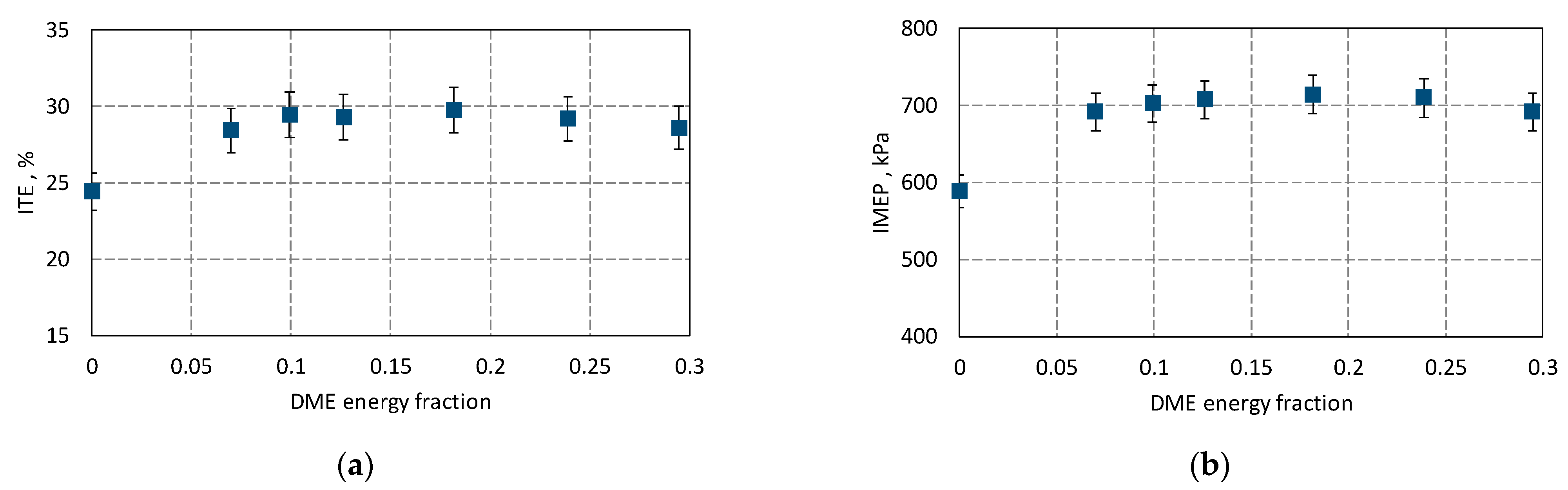
Figure 7 shows the influence of the DME share on the efficiency of an ammonia-fueled engine.
For an engine powered with NH
3 alone, an efficiency of 24.4% was recorded. The addition of DME significantly increased the efficiency of the engine because an 8% share of DME allowed the achievement of an efficiency of 28.4%, i.e., 16% higher than for an engine powered with ammonia alone. This is because DME significantly accelerates the combustion process and, thus, improves efficiency. For 8% DME content, a reduction in the ignition delay time (CA10) and the stabilization of engine operation (COV
IMEP < 5%) were achieved. Below the limit of this DME, contribution cycles without combustion occurred, leading to a reduction in IMEP values. The highest efficiency of 29.8% was achieved for 18% of the energy share of DME. DME is characterized by a much higher LFS in comparison with ammonia, which significantly improves the flame propagation process in the combustion chamber. This likely allows the flame to quickly reach the boundaries of the working space, enhancing the burning of the charge and thereby increasing combustion efficiency. For this DME share, the highest IMEP value of 714 kPa and the minimum specific energy consumption of 12.1 MJ/kWh were recorded (
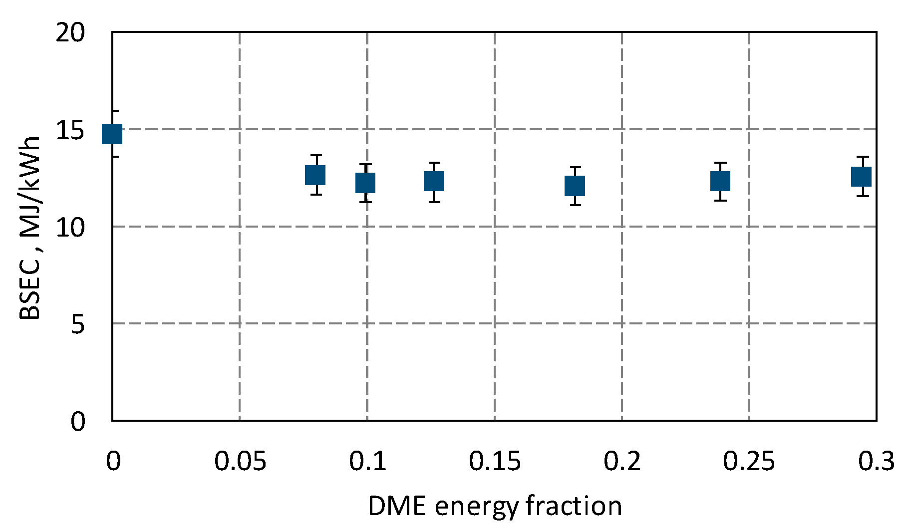
Figure 8). Specific energy consumption is an indicator showing the economics of using the energy contained in the fuel.
An important indicator for assessing the economic aspect of a piston engine is the specific fuel consumption (BSFC in g/kWh). This indicator is reliable only for an engine powered with a single fuel (constant heating value, LHV). In the case in which the engine is powered with two fuels with different heating values and their proportion changes, the BSFC indicator becomes less useful. For dual-fuel engines, the BSEC indicator should be used. It provides information about the energy consumption in the fuel blend to generate one kWh of energy.
As shown in
Figure 8, for all cases of ammonia combustion with the addition of DME, the BSEC value was lower than for the engine fueled with NH
3 alone. This confirms the validity of using fuel with the addition of DME. For an 18% DME share, a BSEC decrease of nearly 19% was achieved. It should be added here that the basic fuel is NH
3, and DME is only intended to enable stable ammonia ignition and/or improve the quality of the combustion process. Varying the DME fraction in an ammonia-with-DME fuel blend for an SI engine affects the ignition timing, flame propagation in the combustion chamber, thermodynamic properties, emissions, and combustion stability. DME has a higher LHV, providing more thermal energy to combustion. Increasing the DME share will influence the heat release during the combustion process.
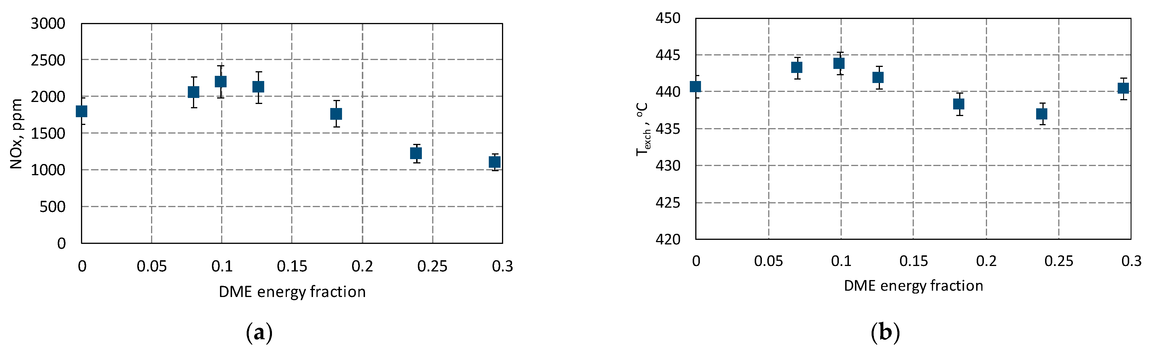
Due to the combustion of ammonia, i.e., a compound of hydrogen and nitrogen, nitrogen oxides (NOx) emissions were controlled.
Figure 9 shows the results of the exhaust gas emission assessment and the exhaust gas temperature obtained during the co-combustion of ammonia with DME in a spark-ignition engine. The combustion temperature significantly impacts NOx emissions in the engine’s combustion chamber. The NOx formation mechanism requires access to nitrogen, oxygen, and a sufficiently high temperature for chemical reactions to occur. Of course, finding the right balance between engine efficiency (including combustion efficiency) and NOx control is crucial to meet environmental standards while ensuring optimal engine performance. The highest NOx emissions were obtained using the co-combustion of ammonia with 10% DME.
In this case, the most intense combustion took place, characterized by the highest temperature (max Texch) and almost the highest heat release rate (dq/dφ). A further increase in the DME share resulted in a decrease in the concentration of nitrogen oxides caused by a decrease in the combustion temperature. This decrease resulted from the depletion of the combustible mixture in the engine cylinder with additional oxygen supplied in DME. For an engine fueled only with NH3, emissions of 1800 ppm were recorded, but this was under conditions of the very high non-repeatability of subsequent combustion cycles; there were cycles without combustion. The highest NOx emission was measured for a 10% share of DME and amounted to 2200 ppm, for this share of DME, the highest exhaust gas temperature was 443 °C. For the energy share of DME considered optimal, the NOx emission was 1764 ppm, which was less than when fueled with NH3 alone. NOx emissions in an engine fueled with a mixture of NH3 and DME can be significantly reduced, thanks to the use of selective catalytic reduction (SCR) technology, and a possible small excess of ammonia in the mixture may be beneficial for the better neutralization of NOx in the SCR reactor.
The oxygen content in the DME atomic structure enhances its combustion efficiency and allows it to burn more completely compared to hydrocarbon-based fuels. When DME burns, the oxygen atoms in its molecular structure participate in the combustion reaction, promoting more efficient and complete combustion. This contributes to a cleaner and more complete conversion of fuel into thermal energy.


