1. Introduction
The extensive integration of electric vehicles (EVs) powered by lithium-ion batteries (LIBs) has undeniably transformed the transportation sector, providing a sustainable and environmentally friendly substitute for traditional internal combustion engine vehicles (ICEVs). Nevertheless, like any technological advancement, electric vehicles pose distinctive challenges and concerns that necessitate comprehensive examination. One of the challenges that has arisen is the occurrence of fires in electric vehicles. This has become a significant area of concern, requiring a thorough analysis to guarantee the safety of passengers, emergency responders, and nearby structures.
During an electric vehicle fire incident, the release of thermal energy can result in a highly dynamic and swiftly evolving environment within a confined structure, such as a parking garage or a residential building. The increase in temperatures and heat fluxes that occur during events like this can have a substantial impact on the structural components in proximity, possibly endangering their mechanical stability. It is crucial to comprehend the reaction of these elements when subjected to extreme thermal conditions to formulate efficient fire safety strategies and improve the overall resilience of electric vehicles.
In lithium-ion batteries, three critical scenarios can occur which lead to extreme operating conditions. These scenarios can result in physical damage, the production of sparks, and the release of flammable gases or toxic fumes, which can potentially initiate a fire. The exposure of LIBs to different load conditions increases the potential hazard of a fire within the vehicle [
1,
2].
From the literature [
3,
4,
5,
6,
7], it was possible to retrieve three primary risk factors for batteries in the automotive sector, which are namely: thermal abuse, mechanical damage, and electrical overloading [
8,
9,
10,
11,
12]. The most common of these is thermal abuse, whose incidence is significantly higher compared to the other cases, primarily because EVs are spread all around the World, even to the most remote regions; therefore the “operating” temperature range is extended from −20 °C to 45 °C and more, when their optimal working temperature is regarded as being between 20 °C and 30 °C. The most dangerous scenario occurs when the battery is exposed to an elevated temperature for an extended duration; the high temperature can start some harmful electro-chemical reactions, causing the LIB to overheat. If there is no possibility of dissipating this heat surplus, it will lead to a phenomenon called “thermal runaway”, characterized by an uncontrolled escalation of cell temperature, which can potentially ignite a fire.
On the other hand, problems related to too-low temperatures must be considered; in fact, low temperatures will raise the internal resistance of the battery, which leads to overheating and consequently increases the fire risk of the vehicle.
Potential damage related to mechanical actions is also common. It is important to acknowledge that the literature presents findings that provide reassurance regarding minor collisions, demonstrating that common protections for LIBs are deemed adequate for this type of accident [
13].
At the same time, the possibility of a battery fire escalates as the driving speed of the vehicle increases; because of this, specialized assessments that appraise the capacity of LIBs to autonomously trigger a thermal runaway in the case of mechanical stresses were developed [
14].
Finally, the last risk factor is linked to the processes of charging and discharging the battery. The pursuit of achieving comparable recharging speeds to those of fossil fuel vehicles has prompted the emergence of fast-charging technology. Nevertheless, this technological solution is accompanied by adverse implications pertaining to the risk of fire. In relation to this matter, it is worth noting that there exist studies that demonstrate the potential consequences of subjecting a battery to excessively fast charging or discharging processes. Such actions can induce a thermal runaway phenomenon within the battery, primarily caused by the Joule effect, which can occur within the lithium-ion battery. This, in turn, can result in elevated temperatures and the inherent risk of spontaneous combustion of the battery [
7,
15]. The term “thermal runaway” is employed to describe a sequence of cascading reactions that surpass the cooling capacity of a system, resulting in excessive heat buildup. The rate at which this phenomenon takes place in the case of LIBs is exceptionally high, approximately 10 °C per minute. This process is often characterized by the emission of dense fumes, sparks, and jet flames. It is important to highlight that this phenomenon is associated with a single cell within the battery, thereby illustrating the potential risks that can arise when considering the entire battery.
Additional factors that contribute to the rising risk of fire incidents in LIBs are associated with non-compliance, including inadequate maintenance practices, manufacturing imperfections, and failures in the safety control systems of the cells [
16].
To mitigate the risk of combustion, LIBs are equipped with a safety valve. This valve is responsible for releasing gases that are generated during thermal runaway. However, the safety valve alone does not guarantee complete safety for the vehicle. The gases released by the safety valve, which are highly flammable, can potentially be ignited by external factors such as open flames, sparks, or electric arcs. Additionally, if the rate at which these gases are produced exceeds the expulsion capacity of the safety valve, it can result in the explosion of the battery.
The fire risk associated with LIBs affects the safety of EVs and the structures that host them. In a previous work from the authors [
17], the structural risk related to fire generated by EVs or ICEVs was compared, based on temperature analysis alone.
This paper aims to present a computational study that focuses on the analysis of the mechanical response of the structural elements, specifically steel pillars, inside enclosed structures when subjected to electric vehicle fires. This research examines the interconnected thermal and mechanical phenomena that take place in such environments by employing advanced numerical simulations and incorporating realistic fire scenarios.
The main goal of the study is to assess the robustness of structures that are subject to EV fires. This will be achieved through an examination of the thermal loads and their impact on the structural components. Furthermore, our intent is to figure out the pivotal factors that exert influence on the mechanical behavior of these components, encompassing material properties, fire dynamics, and ventilation conditions. Using a thorough examination of these aspects, it is possible to acquire significant insights regarding the design and optimization of fire safety measures that can be tailored specifically to electric vehicles and the structures in which these vehicles are parked.
A thermo-mechanical numerical analysis, that could examine the behavior of a steel column under a given static load as the temperature field changes, was carried out. Attempting to replicate these conditions through experimental tests would be impractical, as it would be very burdensome to simultaneously measure both the mechanical and thermal effects accurately. It is noteworthy that this research endeavor allowed for a comprehensive investigation into the dynamic interplay between the critical load of the examined column and the temperature fluctuations. This analysis was made possible through the implementation of a finite element model, which evaluates material strengths, considering contemporaneously the alterations in section geometry brought about by the changing temperatures.
This research offers itself as a base for the formulation of comprehensive fire safety protocols and provides efficient measures to prevent and mitigate fires generated by electric vehicles. Moreover, this work is aimed at contributing to future research endeavors, regulatory frameworks, and design methodologies that are focused on improving the fire resistance of buildings deputed to hosting electric vehicles.
3. Materials and Methods
3.1. Two-Zone Models
A “two zone model” is a numerical model that divides a compartment experiencing fire into two areas with different characteristics (such as temperature, density, pressure, and internal air energy). The physical foundation of this modeling approach lies in the principles of conservation of energy and mass, alongside the integration of a differential problem with partial derivatives.
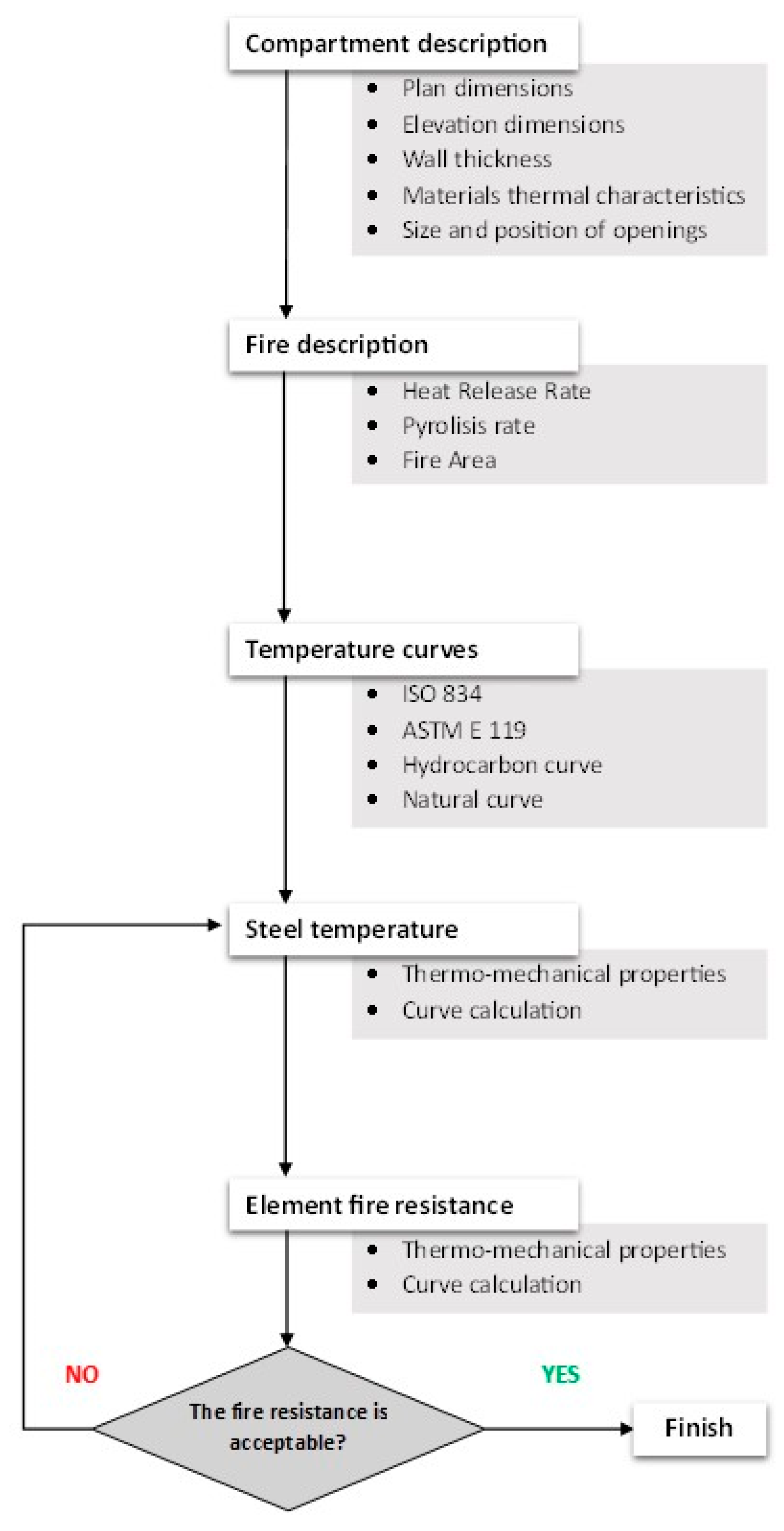
The process of integrating these differential equations over time enables the calculation of the temporal evolution of the variables that describe the gas within each zone. The mass balance equation states that the change in mass of the gas within a specific area is equivalent to the sum of the mass of combustion gases produced by the fire, the mass entering the compartment through the vents, and the mass exiting the compartment through the vents. The energy balance equation represents the equilibrium between the energy generated through combustion within a compartment and the various mechanisms through which this energy is lost. These mechanisms include the heating of gases within the compartment, the loss of hot air through openings (including a negative term to account for the energy associated with incoming air), radiation loss through openings, and the heating of partitions [
22,
33,
34]. The procedure to correctly define a two-zone model is presented with a flow chart in
Figure 4.
The standard set of physical variables used in numerical two-zone models is eleven. The mass and energy balances in each zone are connected by seven restrictions and four differential equations. The gas variables in each zone may be calculated by time-integrating these differential equations. The mass balance equation shows that the change of a zone’s gas mass at any time is equal to the mass of combustion gases generated by the fire, plus the mass that enters the compartment by means of the vents reduced by the mass going out of the compartment.
This model utilizes a methodology that consists of dividing each compartment into two homogeneous zones to calculate the conditions determined in the entire environment. The upper region refers to the area where combustion by-products, such as fumes and hot gases, are found. The second area is situated at a lower elevation, devoid of smoke, and characterized by cooler temperatures compared to the upper area.
The vertical dimension ratio between the two zones changes as the fire progresses. Zone models have the capability to estimate various parameters over time. These parameters include the temperatures of the lower and upper layers, the position of the interface between the zones, the concentration of oxygen, the concentration of carbon monoxide, the visibility, and the flow of air through openings in an outward direction [
22,
34].
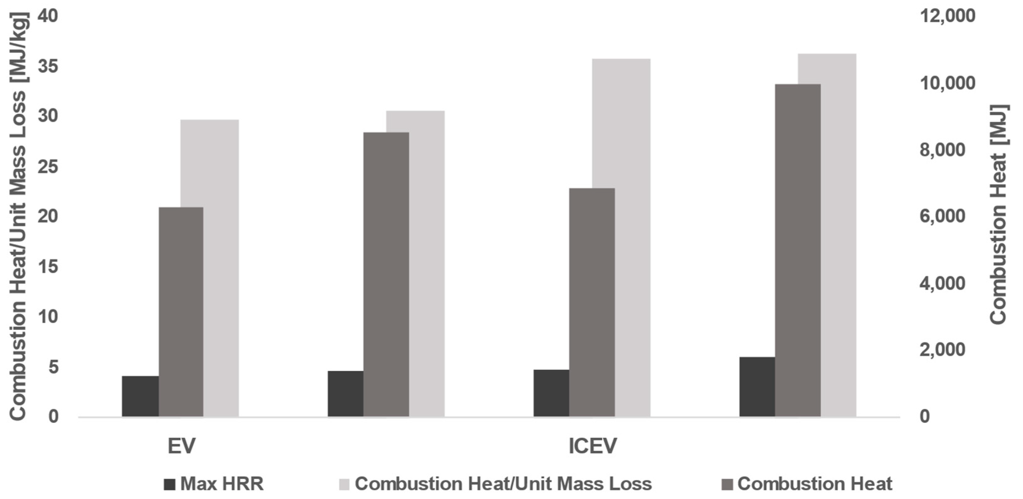
In this work, a two-zone model was used to obtain the temperature curves without introducing too much input data, difficult to provide in ordinary fire engineering activities with a sufficient level of accuracy. To obtain the most accurate results, we relied on actual heat release rate (HRR) curves for electric vehicles (EVs) and internal combustion vehicles (ICEVs) [
23,
31,
32,
38,
39]. This choice is crucial to ensure that the simulations were anchored in reliable empirical data and accurately reflected the thermal behavior during real fires in vehicles of different types. The use of real HRR curves for both vehicle types allowed us to comprehensively compare and analyze the thermal responses of structural elements within closed structures during EV and ICEV fires.
The final temperature curves and the real fire load considered were determined by considering the regulatory prescriptions for garages [
40,
41,
42,
43].
3.2. Thermo-Mechanical FE Models
To evaluate the thermo-mechanical behavior of the steel columns, a FEM model is realized in ABAQUS [
44]. In addition, it was decided to consider the geometric non-linearities and buckling phenomena typical of slender sections. An initial buckling analysis was therefore set up, the results of which form the basis of the subsequent thermo-mechanical analysis in which the steel element is subjected to a vertical load, simulating the action due to the superstructure, and a thermal load simulating the fire.
The variation of the critical load for the column was also examined as the temperature varies, as the finite element model allows the strengths to be assessed by also considering the change in the form of the section.
It is relevant to note that this type of analysis can only be conducted in a numerical environment, as an experimental test would not allow the simultaneous action of a mechanical load and a thermal gradient to be assessed.
Developing a test setup that evaluates the same type of interaction is very complex, and there are two possibilities: either an oven test on the structural element or a controlled fire test in an existing structure. Carrying out an experimental test in which a fire load and a mechanical load are applied at the same time would not allow some of the quantities of interest to be measured (thermocouples could be inserted, but it would be difficult to monitor the displacements of a given control point), as the sensors would not be able to withstand the temperatures reached in the test furnace. On the other hand, in a controlled fire test, only the design thermal load can be reproduced, not the temperature trend (the HRR would be significantly different), which would take on a more random value and be linked to the conditions of the fuel present, thus breaking the basic principle of reproducibility of the experiment.
In situations where the stress analysis is influenced by the temperature distribution and the temperature distribution is reliant on the stress solution, a comprehensive thermal stress analysis that accounts for the interdependence of these factors becomes mandatory. This is the kind of challenge that could be encountered in the modeling of metal structural elements, which involves the occurrence of substantial thermal effects resulting from the inelastic deformation of the material. In instances of this nature, it is necessary to acquire thermal and mechanical solutions concurrently, as opposed to following a sequential approach. Both ABAQUS/Standard and ABAQUS/Explicit offer coupled temperature–displacement elements for addressing this objective, even if these programs employ distinct algorithms for solving coupled thermal-stress problems.
The coupled thermo-mechanical analysis necessitates the utilization of elements that possess both temperature and displacement degrees of freedom and can be employed to examine the time-dependent behavior of materials.
In ABAQUS/Standard, a fully coupled thermal-stress analysis disregards the influence of inertia effects and can be either transient or steady-state in nature; otherwise, a fully coupled thermal-stress analysis in ABAQUS/Explicit encompasses the inertia effects and the modeling of transient thermal response.
3.2.1. Standard Thermo-Mechanical Analysis
The integration of temperatures in ABAQUS/Standard is accomplished through the implementation of a backward-difference scheme, while the resolution of the nonlinear coupled system is achieved by employing Newton’s method. ABAQUS 2017/Standard software provides both a precise and an approximate implementation of Newton’s method for conducting fully coupled temperature–displacement analysis.
The precise execution of Newton’s method necessitates the utilization of a Jacobian matrix that is not symmetric:
where the corrections to the incremental displacement and temperature are denoted as Δ
u and Δ
θ, respectively. The submatrices of the fully coupled Jacobian matrix are represented as
Kuu and
Kθθ. The mechanical and thermal residual vectors are denoted as
Ru and
Rθ, respectively.
The resolution of this system of equations necessitates the utilization of the unsymmetric matrix storage and solution scheme. In addition, it is necessary to solve the mechanical and thermal equations concurrently. Quadratic convergence is observed in cases where the solution estimate falls within the algorithm’s radius of convergence.
In some cases, the coupling between thermal and mechanical solutions could be weak; in other words, the secondary elements of the Jacobian, i.e.,
Kuθ and
Kθu are smaller than the diagonal components. In such cases, it is more effective to approximate the Jacobian as:
Due to this approximation, the thermal and mechanical equations can be solved independently, resulting in a reduced number of equations to be addressed in each respective subproblem. The approximate method will result in significant savings in terms of solver time per iteration, estimated to be approximately twice as fast. Additionally, there will be comparable savings in solver storage required for the factored stiffness matrix. Moreover, it is worth noting that in numerous scenarios, the subproblems exhibit complete symmetry or can be reasonably approximated as symmetric. Consequently, this allows for the utilization of a more cost-effective storage and solution scheme that is specifically designed for symmetric problems. The time saved by using a symmetric solution is twice as much.
The solution accuracy of this modified version of Newton’s method remains unaffected, as it accounts for the fully coupled effect by considering the residual vector at each time increment. Nevertheless, the convergence rate deviates from being quadratic and is heavily influenced by the magnitude of the coupling effect. Consequently, a greater number of iterations is typically required to attain equilibrium compared to the precise application of Newton’s method. When the degree of coupling is substantial, the rate at which convergence occurs becomes notably sluggish, potentially impeding the attainment of a solution. In instances of this nature, the precise execution of Newton’s method is necessary [
44].
3.2.2. Explicit Thermo-Mechanical Analysis
The heat transfer equations in ABAQUS/Explicit are integrated utilizing the explicit forward-difference time integration rule:
where the temperature at node
N is denoted by
θN, and the subscript
i represents the increment number in an explicit dynamic step. The forward-difference integration method is considered explicit as it does not require the solution of any equations when employing a lumped capacitance matrix. The actualized temperatures are derived by utilizing established values of
from the preceding interval. The values of
are computed at the beginning of the increment by:
where
is the lumped capacitance matrix,
is the applied nodal source vector, and
is the internal flux vector.
The mechanical solution response is acquired by means of the explicit central-difference integration rule while using a lumped mass matrix. The simultaneous obtaining of heat transfer and mechanical solutions is facilitated through an explicit coupling of the forward-difference and central-difference integrations, as both methods are explicit. Hence, there is no need for iterations or tangent stiffness matrices [
44].
4. Case Study
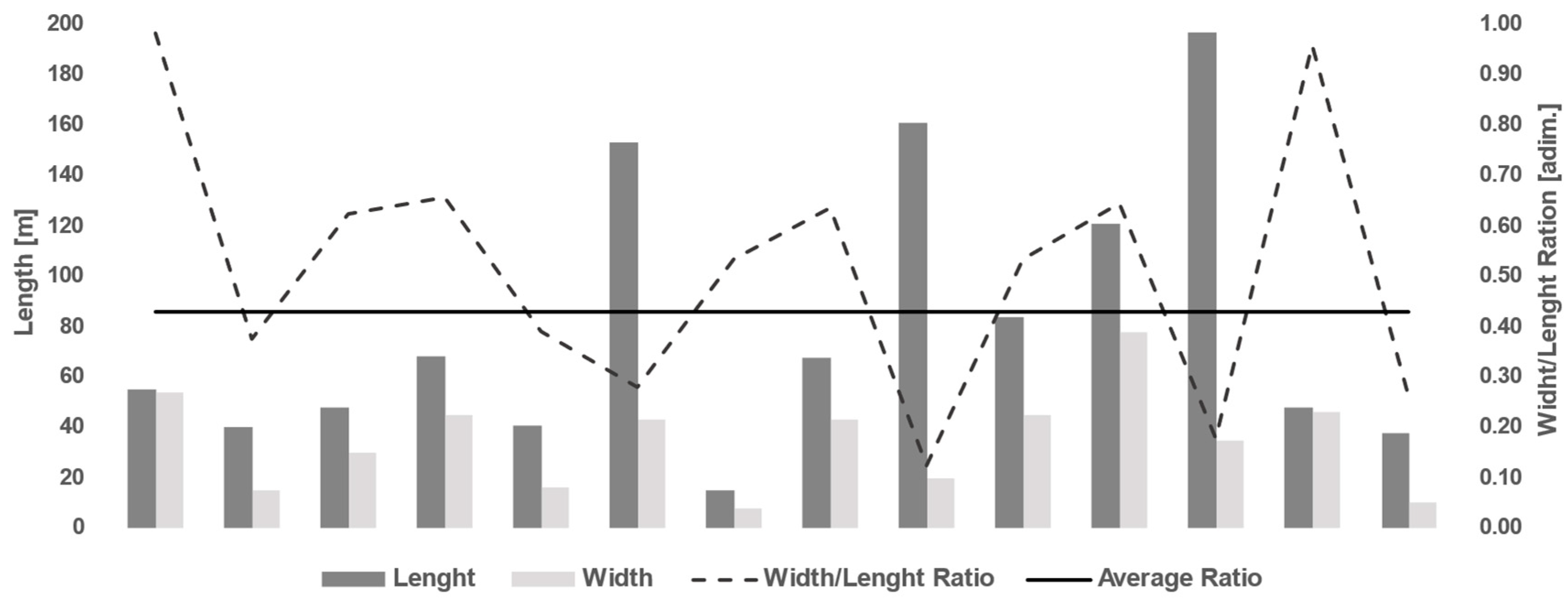
This work is focused on the response of steel columns placed in a generical garage, the dimensions of which were defined on the basis of a statistical survey, summarized in
Figure 5, carried out on buildings of the same type within Bari, a middle-sized town in the south of Italy.
The coupled thermo-mechanical response was developed for one of the load-bearing columns of the structure, using a combination of finite elements and two-zone models. To assess the deflection of the pillar, the mechanical response of the structure was evaluated. This parameter is more immediate to estimate (this can be achieved through simple visual inspections and laser measurements) and does not require intervention with destructive tests. In addition, considering deformations, we can establish a risk index based on the regulatory prescriptions for maximum admissible deflection values already at the Limit States of Operation.
4.1. Two-Zone Model and Data
A compartment of approximately 5000 m
2 is considered the maximum fire area (in compliance with the standard prescriptions regarding the maximum dimensions of compartments for above-ground garages on the ground floor [
40,
41,
42,
43,
45]), a value obtained by considering all the necessary spaces inside the building for car transit routes, pedestrian routes, ramps, accesses, stairs, and lifts.
These standards and their addendum, in some requests for clarification received by the fire brigade and implemented in subsequent updates, also provide a maximum number of vehicles that may be present per compartment in the case of garages or parking garages with a capacity of more than nine vehicles; this limit is recommended, not prescribed, and is approximately 25–30 vehicles per compartment, depending on the size of the compartment. In this work, the compartment of the garage is supposed to host 25 cars; this number was chosen after some consideration of the space management within the garage.
The temperature curves obtained from the zone model built in OZone were exported to the FE model in ABAQUS. Namely, the curves are relative to:
- -
compartment temperature in the hot zone part for both EVs and ICEVs;
- -
steel temperature at the external surface of the columns for both EVs and ICEVs (columns are assumed to have no thermal insulation coating).
These curves represent the real natural curves for the design fire case. Since it was possible to obtain the temperatures of both the hot zone of the compartment and the temperatures of the outer steel layer, it was decided to represent both possibilities in the numerical environment. The steel profile temperature is determined using EN 1993-1-2 [
43]. The calculation is developed on the basis of different scenarios proposed by the standard. Each scenario assesses the height of the interface between the hot and cold zones. In the case of a uniformly distributed fire load, the temperature measured on the structural element will only depend on its interaction with the two zones and their time evolution [
34]. Differently, the “hot zone” temperature is the maximum temperature reached by the gases in the compartment [
34]. From here on, reference will be made to the two heating curves considered “hot zones” for the temperature curve of the compartment and “steel” for the curve relating to the heating of the outer layer of the column only.
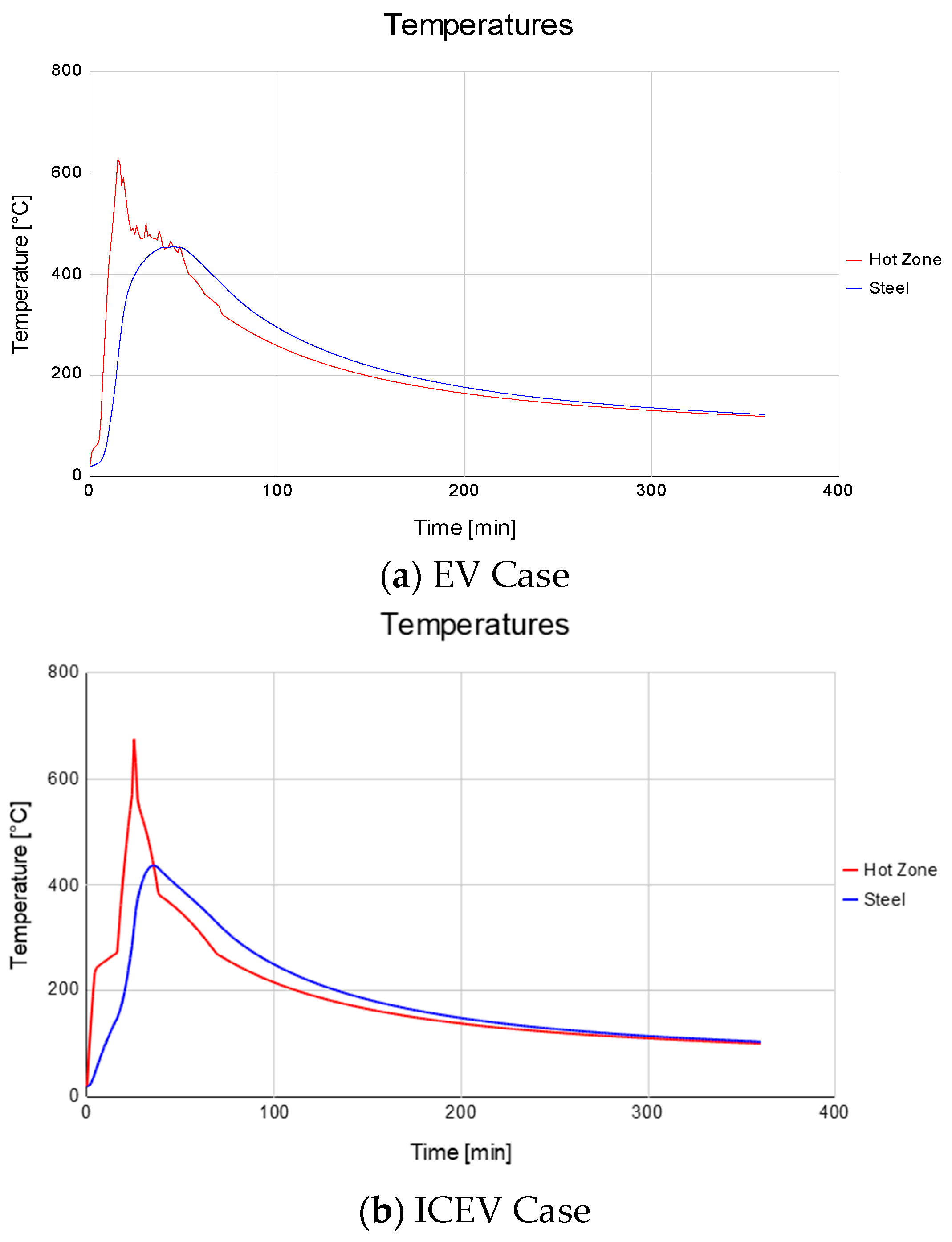
As can be seen from
Figure 6, the maximum temperatures reached are closer for both EVs and ICEVs; a relevant difference is in the duration and the timing of the peak. In fact, a fire generated by EVs exhibits a temperature peak earlier than ICEVs and will keep higher temperatures for a longer period. It turned out that the maximum temperatures reached were 675 °C at 25 min in the compartment, which corresponds to a maximum temperature of the steel of 437 °C at 35 min in the case of internal combustion cars fire (ICEVs). In the case of electric vehicle fires (EVs), the maximum temperature reached in the compartment was 628 °C at 15 min, and steel reached a maximum temperature of 455 °C at 45 min.
After defining the thermal action in the two-zone model, a finite element model is constructed in ABAQUS to evaluate the response of the load-bearing, steel column to the joint action of thermal and mechanical loads.
4.2. ABAQUS FEA Model and Data
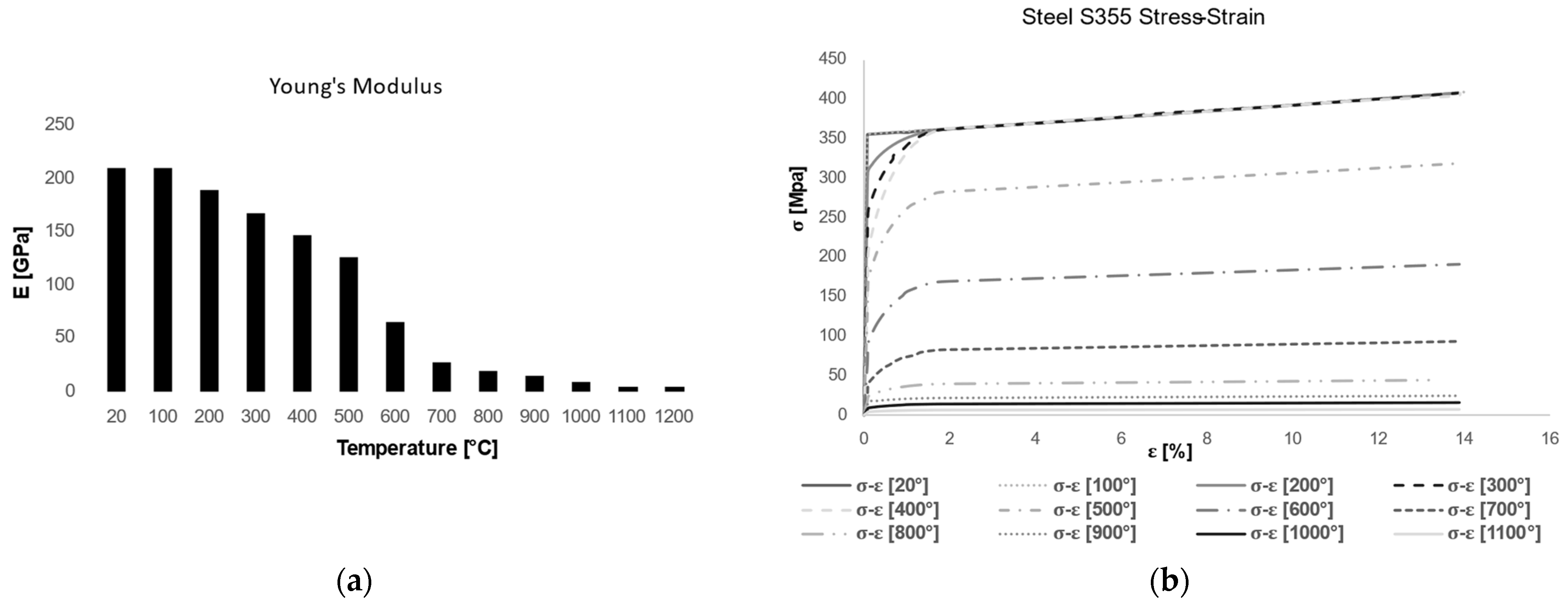
The column considered has a HEB400 cross-section. The pillar is modeled as a three-dimensional, discretely deformable element to which the material considered is associated, that is steel S355, with a density of 7850 kg/m
3. Since the purpose of the analyses is to evaluate deformations in both the elastic and plastic fields, it was necessary to fully describe the constitutive behavior of the material, as well as its fire behavior. Since these are coupled thermo-mechanical analyses, it is also appropriate to consider the dependence of the material characteristics with respect to the temperature they are subjected to. Therefore, the different elastic moduli of steel at different temperatures were defined, while keeping the Poisson’s coefficient constant at a value of 0.3. Similarly, the different stress–strains at different temperatures were defined in a punctual manner using the ABAQUS ‘plastic’ constitutive bond, which is designed to precisely model the post-elastic behavior of metals. Conductivity and specific heat were also defined as the temperature changed, as shown in the graphs (
Figure 7 and
Figure 8), while a value of 1.2 × 10
−5 was assumed as the expansion coefficient.
To model the thermal exchange between the fire environment and the column, thus considering not only the conduction phenomenon in the steel but also the convective and radiative mechanisms, two additional parameters were defined: the thermal convection coefficient and the emissivity. The thermal convection coefficient, assigned by means of a film coefficient, is set equal to 25 W/m2 °C, while the emissivity of 0.3, a typical value for steel, is associated with surface radiation.
The vertical load is set at 3750 kN and considered to be distributed over the entire upper face of the column while the three different thermal inputs were analyzed.
The ABAQUS library contains a lot of solid (continuum) elements that can be made of a single homogeneous material or multiple layers of different materials for laminated composite solids. In this case, C3D8T elements were used, which are eight-node trilinear elements, capable of capturing both mechanical and thermal actions. The model consists of a total of 57,600 elements and 87,591 nodes.
Regarding the development of the test, both the mechanical load already mentioned and the thermal load, expressed through the application of heating curves, are applied simultaneously via ABAQUS.
The thermal load in the numerical model was applied in the form of different curves of temperature–time, as obtained by the previously described two-zone model.
The thermal loads were defined by means of a boundary condition at the column surfaces [
35,
37].
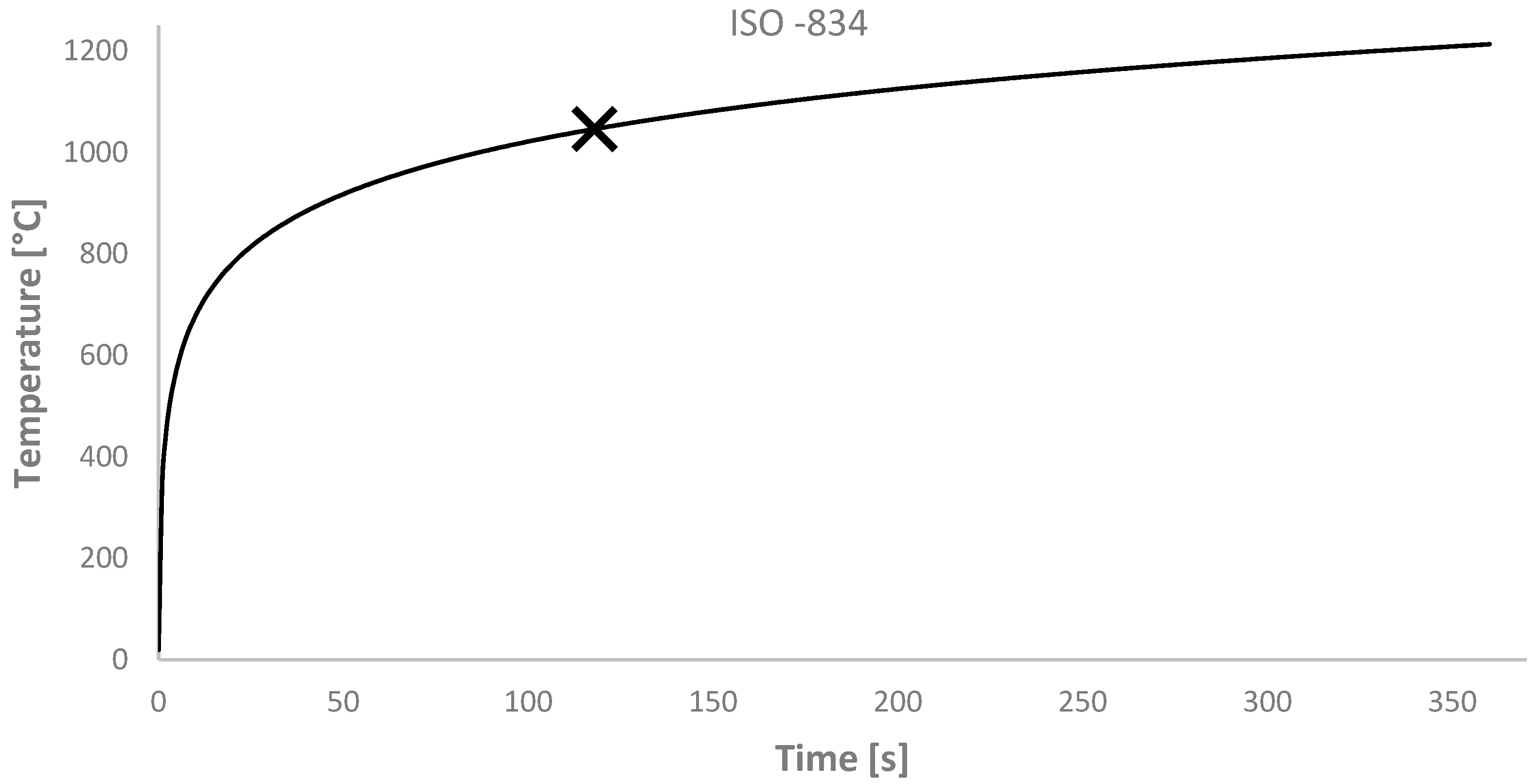
In fact, for the purposes of the investigation conducted, several models were realized in ABAQUS; in particular, in the case of thermal actions resulting from vehicle fires (both EVs and ICEVs), four different models were realized, each relating to a particular load condition, which will be better explained in the following section of performance analysis. Furthermore, as the investigation was applied to a structural element, a final model was developed, with the application of the ISO-834 standard curve [
46]. This approach was proposed by other authors, who performed some experimental tests on materials and structural elements when applying a thermal gradient that follows the trend of the standard ISO-834 curve [
47,
48,
49,
50,
51].
4.3. Fire Resistance According to Regulations
To identify a practical application of the method, we referred to a well-known approach to describe the thermo-mechanical response of the structure to the active loads. In this case, it was decided to refer to Eurocode 3: Design of steel structures—Part 1–2: General rules—Structural fire design and to consider the fire resistance index (R) [
43].
The fire resistance requirements for structures (resistance classes R30/R60/R90 …) are set by current regulations. These requirements are generally set based on the intended use of the buildings, the height and floor area of the building, the fire load, the number of people, and the effect of the protective measures adopted such as, for example, sprinklers, fire hydrant network, smoke and heat evacuators, detection systems, ease of access for fire-fighters, etc.
In accordance with the requirements of the standard, the verification is conducted considering that the compartment must exhibit a class of at least REI-120.
Referring to the simplified calculation methods given in Eurocode 3, the minimum fire resistance class R is calculated for the column. These methods still follow a prescriptive approach, in which the actual temperature distribution in the structural element is not considered. Within the scope of this work, reference is made directly to Eurocode 3.
The preservation of the load-bearing capacity of a steel member in a specific fire scenario can be determined by comparing the design effect of actions for the fire design situation (
Ed), as defined by EN 1991-EN-1-2, to the corresponding design resistance of the steel member (
Rd,t) at time
t. If
Ed is less than or equal to
Rd,t, it can be assumed that the load-bearing function of the steel member is maintained [
43].
The determination of the design resistance
Rd,t at time
t often involves considering a uniform temperature distribution over the cross-section. This is achieved by adjusting the design resistance for normal temperature design according to the guidelines outlined in EN 1993-1-1 [
52]. The purpose of this modification is to include the mechanical characteristics of steel at increased temperatures.
The design resistance for normal temperature design according to EN1993-1-1 is adjusted when a non-uniform temperature distribution is used. In an alternative approach, the verification process may be conducted in the temperature domain by using a uniform temperature distribution [
43].
In this case, the method chosen is the one that refers to critical temperatures.
The degree of utilization, m0, for members of Class 1, Class 2, or Class 3 cross-sections, as well as for all tension members, may be determined using the equation: m0 = Ed/Rd,0 where Rd,0 represents the resistance value, Rd,t, for t = 0.
The calculation of the utilization coefficient is conducted both in the case of pure compression and in the case of the buckling phenomena. Profile type HEB400 is classified as a Class 1 element, while the restraint condition relating to the determination of the free length of deflection is that of a column embedded at the base and hinged at the top; therefore, the coefficient b is unitary.
Considering the stress resulting from the loads on the structure, in combination with the limit states, we find that Ed is 3750 kN.
The compressive strength of the column in the case of a centered compressive state is found to be Nc,Rd = 6687 kN.
In the case of the presence of buckling phenomena, the verification is conducted in both x and y directions; it was found that Nb,Rd,x = 6620 kN, while Nb,Rd,y = 5830 kN.
The critical temperature, denoted as θcr, is the temperature at which a member is predicted to fail under its designated loading conditions. The determination of the member’s failure mode, especially in cases when instability is not a factor, may be achieved by using the degree of utilization (μ0) of the member in the fire design scenario.
It follows that the values of the utilization coefficient and the relative critical temperatures are:
To ensure the structural integrity of an element under fire conditions, it is necessary that the critical temperature of the element, when subjected to design loads, must always be higher than the design temperature during the fire event and until the specified duration. This approach is applicable only when the behavior of the member is primarily influenced by a single representative temperature, as is the case of steel members experiencing uniform temperature distribution.
The compartment, referring to the Italian standard for fire prevention in garages, requires a class of at least REI120 for the compartment walls. Transposing this consideration to the resistance of the structural elements will result in the column examined meeting a resistance class of at least R120.
As can be seen from the course of the ISO-834 curve in
Figure 9, it appears that at 120 min, in the compartment, a temperature of 1049 °C is considered, well above the calculated critical temperatures. The selected section HEB 400 in this case would not meet the minimum requirements; therefore, a protective coating would have to be provided.
4.4. Fire Resistance with Performance-Based Method
Eurocode 3 also allows for the use of complex calculation models that are rooted in basic physical principles. These models provide a realistic study of structural behavior during fire incidents. These entities may be used to depict the conduct of individual constituents, the whole framework, or sub-components. Computational approaches, to varying degrees, exhibit approximations, rely on distinct assumptions and do not universally possess the ability to forecast all conceivable forms of behavior. Hence, it is essential that the client, designer, and competent building control authority reach a consensus on the validity of any model included in the design analysis.
Computational models have the capability to simulate the thermal behavior of a building in response to a specific fire scenario, whether it is a standard or variable situation. These models should not just rely on recognized principles of heat transport but also include the known variations in thermal material characteristics as a function of temperature. The more sophisticated models may consider non-uniform thermal exposure and the transport of heat to surrounding structures. Given that the impact of moisture content on protective materials is inherently an added safety measure, it is permissible to exclude this factor from the study.
When doing structural analysis to predict the mechanical behavior of structures, it is essential to adhere to established principles of structural mechanics, considering the variations in material characteristics that occur as a result of temperature changes. The inclusion of thermally generated stresses and their corresponding consequences resulting from temperature increases and differentials is essential. The consideration of geometric non-linearity becomes crucial in the modeling of domains characterized by significant structural deflections. Similarly, the incorporation of material non-linearity becomes vital when stress–strain curves exhibit strongly curved behavior. However, it is widely recognized that transient thermal creep does not need to be explicitly considered in the context of unintentional fires occurring within a certain time frame. This is because the elevated-temperature stress–strain curves supplied in the applicable code are sufficient for analysis and design purposes. This assumption may be subject to reevaluation during the cooling phase of naturally occurring flames.
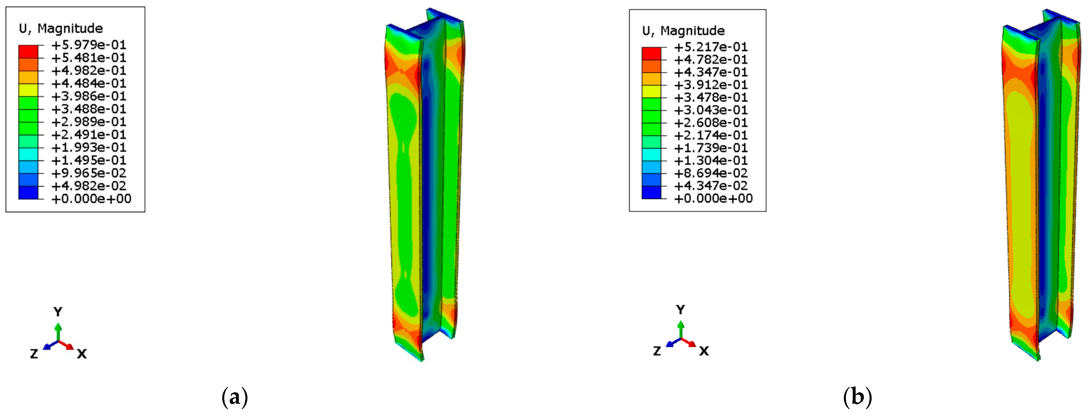
The numerical analysis phase saw the realization of four different models, each based on different boundary conditions; in fact, the preliminary objective of this work is to understand how far it is possible to go with the simplification of the starting physical problem. Four separate models and numerical tests were therefore developed for the electric vehicle case:
Temperature only: both instability phenomena and the static load present are neglected, see
Figure 10;
Temperature and static load: in this model, only the phenomenon of instability is neglected, see
Figure 11;
Temperature and buckling only: this model was built to see whether temperature could actually play a significant role in the axial buckling of the column, see
Figure 12;
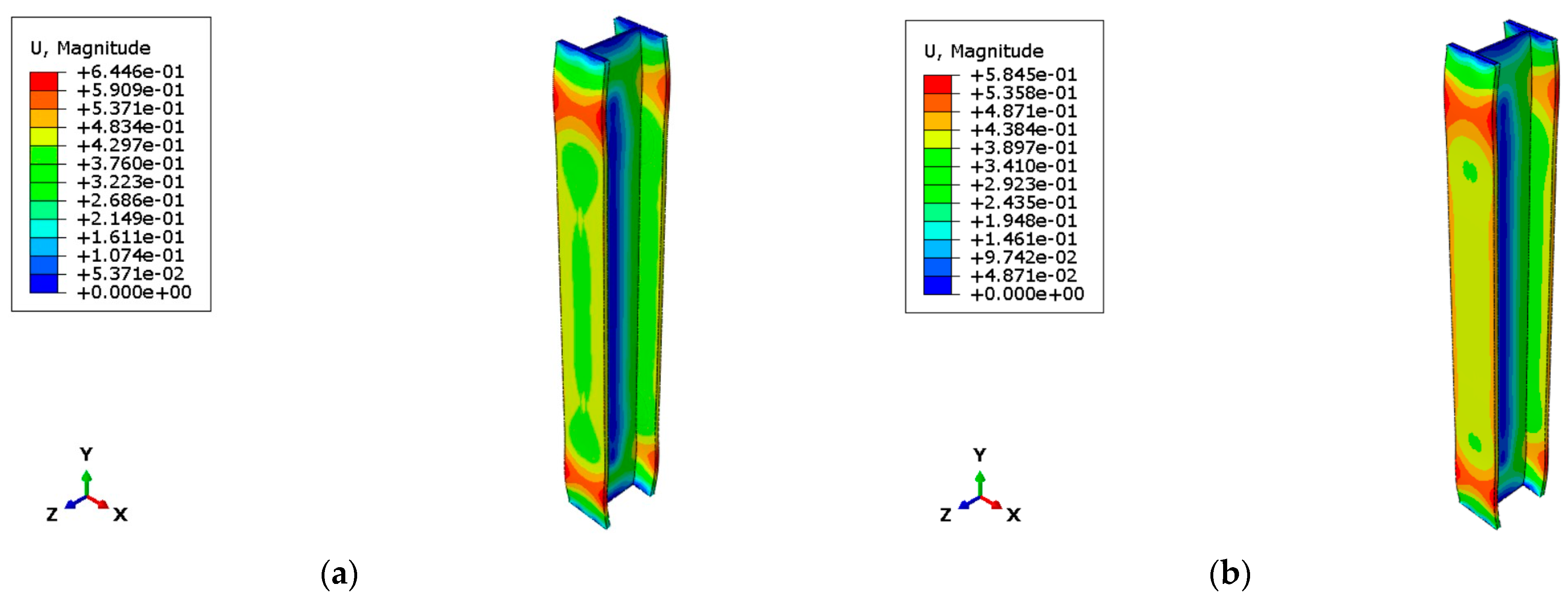
Complete model with all loads and imperfections resulting from the buckling phenomena, see
Figure 13.
It became evident that the first two models, which do not consider the phenomenon of flexural instability of the column, are not adequate as the response in terms of deflection was unrealistic, as they always fall into the case of perfectly centered compression stress. The third model, on the contrary, was extremely useful to understand the actual contribution of the thermal gradient to the total deformation. It was observed that temperature has an influence on deformation of between 25% and 35%; this deviation depends precisely on the maximum temperatures developed by the fire. In fact, in the case where the maximum temperature of the hot zone is applied, the greatest deformations were recorded, and the deformation due to thermal action alone accounted for 35% of the total deformation. In contrast, in the case of the steel heating curve, the temperature contribution is only 25% of the total.
The complete model takes into account thermal and mechanical stresses and basic nonlinearities, capturing the essential physics of the phenomena.
All these models were made for both the case of EVs and the case of ICEVs; for the sake of brevity, only the results for the EVs are shown in the figures above.
Once it was established that the complete model is the most realistic model for both EV fires and ICEV fires, another model was implemented: one corresponding to the application of the ISO-834 curve, commonly used as a reference for the design and verification of compartments in case of fire.
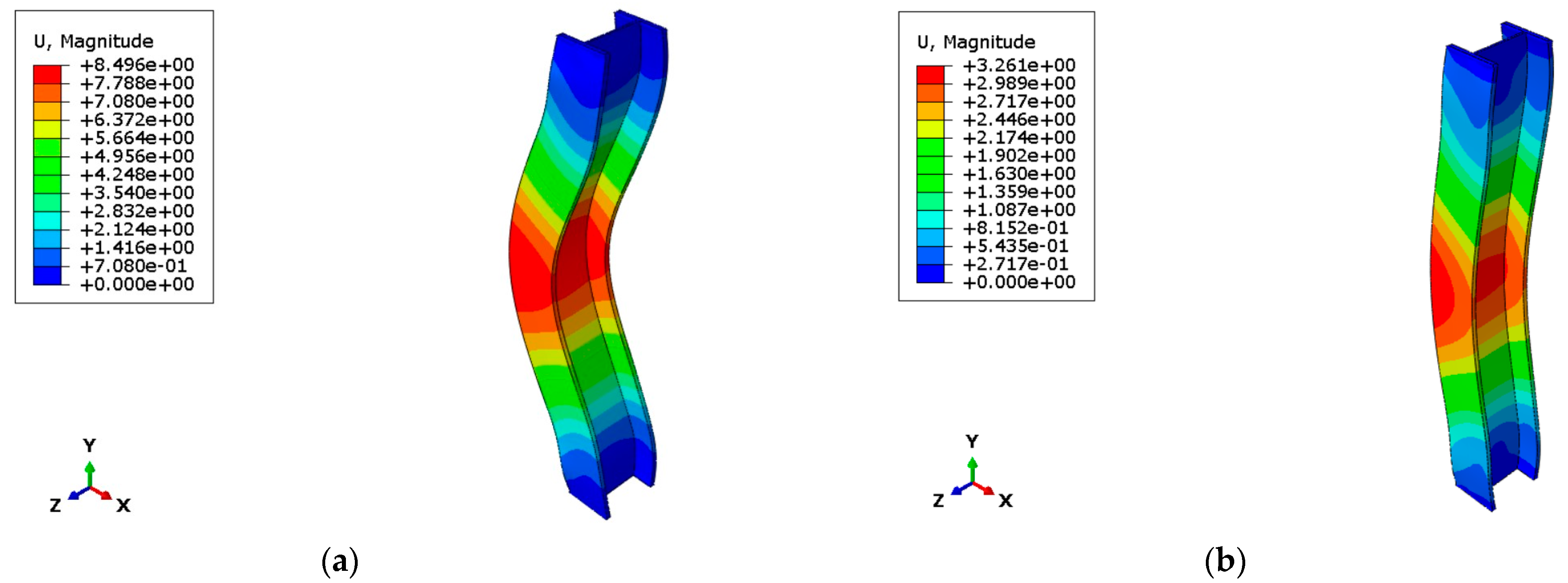
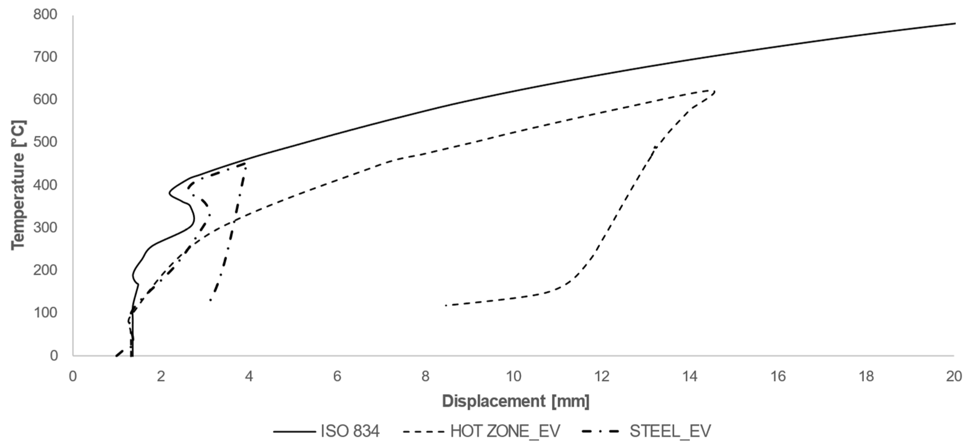
Deformations were evaluated in terms of displacements at the column’s middle section. The temperature–displacement curves obtained by applying the different heating curves are shown in
Figure 14 and
Figure 15.
The maximum deformations reached are 3.92 mm for the steel heating curve, 14.5 mm for the hot zone (compartment) curve, and 64.77 for the ISO 834 curve.
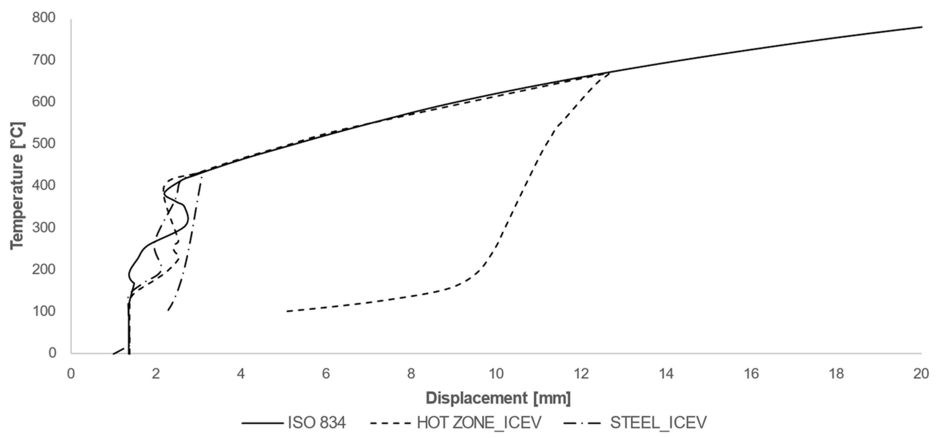
In the case of ICEVs, the temperature–strain trend is much closer to that of the ISO curve, although it is evident that the ultimate strain reached in the case of the natural curves (hot zone and steel) is considerably lower than that given by the standard curve. In this case, the maximum strains reached are 3.10 mm in the case of the steel curve and 12.63 mm in the case of the hot zone curve. It should be observed that the ISO curve does not have a cooling phase; therefore, the column subjected to that heating does not exhibit the elastic deformation release phase.
The fire resistance (R) is always defined with reference to the critical temperature. Performing a check, directly on the temperature curves, would be unacceptable. In fact, considering the hot-zone curve, it can be seen that the maximum temperatures reached in the compartment exceed the critical temperature before 30 min. Considering this, the column would be classified as REI-15. According to the regulatory prescription, such a fire resistance level is not sufficient for structural safety, and it would be necessary to resort to an insulating coating. Conversely, with the steel curve, the critical temperature is never exceeded, both in the case of EVs and in the case of ICEVs. In this case, the column is always classified as REI-120, resulting in an unrealistic evaluation because the associated deflections are higher than the acceptable limit.
Thus, a necessary step is represented by the thermo-mechanical analysis; the evaluation of the deformations of the load-bearing element can provide concrete indications of the state of health of the column as the fire progresses.
4.5. Risk Index
In terms of deflection, no risk index in the literature is defined for vertical elements; therefore, one is determined based on the minimum permissible deflection for the structure. It should be emphasized that this type of consideration falls within the scope of verifications at the serviceability limit states, but in the case of the buckling phenomena, the collapse resulting from the loss of strength determines the failure of the individual element. In defining a risk index for the structural element under investigation, reference is made to BS 5950-1:2000 [
52,
53,
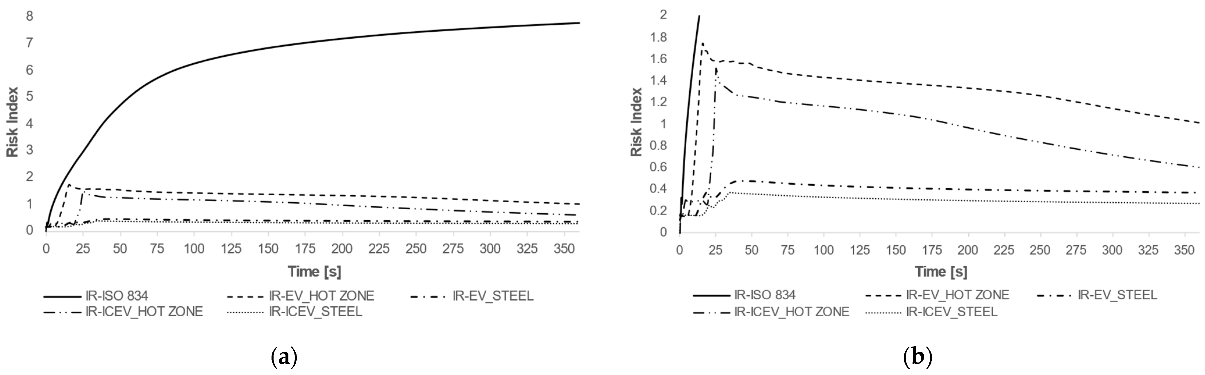
54], which imposes a maximum deflection for a steel column of H/360, resulting equal to 8.33 mm in the present case. We proceeded by normalizing the deflection value against this limit value to define a risk index. The numerical model allows an assessment of the failure risk of the element in its transient domain. A simple ex-post analysis would only evaluate the ultimate value of deflection reached by the structure, not considering the temporal evolution of the deformation state of the structure during the fire. The curves presented in
Figure 16 represent the trend of the risk index (RI) obtained by normalizing the displacement measured by the FE model with the limit displacement allowed by the Technical Regulations.
It can be seen that the application of the ISO 834 curve is largely unfavorable for the structure, leading to RI = 1 being exceeded already at the initial stages of the fire, i.e., in the first 10 min of the test; the other curves, on the other hand, show how the application of the actual curves is less drastic in defining the risk related to the load-bearing capacity of a structure subjected to a fire. Certainly, the application of the compartment temperature curves is to the advantage of safety, as they represent the most unfavorable conditions. It should also be observed that the fire generated by electric cars leads to a slightly higher risk index than that of classic ICEVs, whether referring to compartment temperature or column temperature. It is evident how the application of the ISO curve leads to a considerable overestimation of the effects of fire, which then implies a great expenditure of resources, both economic and raw materials, during the construction phase, making the structure unsustainable, particularly from an environmental point of view.
The risk index defined in this way can be a useful tool for designers and technicians called upon to intervene in a structure that has suffered a fire. In fact, starting from the knowledge of the temperatures reached or the fire load present (even in an approximate line), it is possible to estimate the time evolution of damage in the resistant elements. This estimate is certainly an important factor since post-fire operations to secure the area are always extremely risky for the personnel called upon to operate. A risk index based on temperatures, on the other hand, makes it possible to quantify the level of damage reached based on the type of fire developed and to appropriately plan the investigations and interventions to be carried out for the restoration or demolition of the structure.
5. Conclusions
The objective of this study was to examine the thermo-mechanical behavior of a load-bearing steel column when exposed to fire generated by different causes.
The first aim was to understand if EVs could represent a higher risk for structures with respect to ICEVs. To do this, numerical analysis techniques were employed, specifically finite element modeling (FEM) and two-zone models, to evaluate the performance of the steel column when subjected to both thermal and mechanical loads.
The finite element method (FEM) model implemented in ABAQUS is designed to simulate the buckling phenomena of the steel columns. This is of utmost importance as it enables an accurate simulation of the column’s behavior under fire-induced loads. To accurately depict the mechanical response of steel under elevated temperatures, the influence of temperature on the material properties is also considered.
An initial investigation was carried out to define the best possible FE model to identify the level of simplification that could be achieved in the representation of the physical problem. The creation of various models also made it possible to determine the contribution of temperature to column deformation, which was found to be between 25% and 35% as the temperature increased.
Comparing the different vehicle types, it was observed that the peak temperature in the compartment shifted slightly over time. In fact, we observed 675 °C for EVs at 25 min, while only 628 °C for ICEVs at 15 min. What was demonstrated here was that electric vehicles lead to higher temperatures over a longer period, which leads to greater deformations on the resistant elements of the structure. In contrast, the analysis of the temperatures on the column showed that the ‘cooling phase’ in a fire fueled by electric vehicles alone occurs earlier and more abruptly, leading to a maximum temperature on the column of 437 °C at 35 min, which is lower than the maximum temperature of 455 °C at 45 min for ICEVs.
A comparison was also developed between the prescriptive methods indicated by the Eurocodes and the performance method, linked to the actual representation of the fire. Standard methods tend to be either overly cautious or demand intensive computational efforts. It is evident how the application of simplified methods leads to an overestimation of the consequences and effects of the fire, with a consequent waste of resources both in the design phase and in the eventual recovery phase. Modern technologies have made CFD methods more attainable, but they still remain impractical for professionals. As a result, many of them still use tabular methods, despite their tendency of being excessively on the conservative side. This work prompted an exploration of a middle-ground approach, bridging the gap between basic and detailed analyses.
The comparison with the standard curve also showed that considering the actual fire load, the maximum temperatures reached are almost half of what is prescribed by the ISO 834 curve. As far as the comparison is concerned, what emerged is that, in the end, electric vehicles are no more dangerous than internal combustion vehicles in terms of fire consequences.
On the design side, however, it was highlighted that the application of simplified tabular methods does not always lead to optimal results; on the contrary, over-dimensioning of protection strategies is common. For this reason, it is more appropriate to refer to performance methods, with the application of natural heating curves.
A risk index (RI) was developed to evaluate the risk level associated with the structural element by comparing the maximum displacement of the column with the permissible deflection specified in BS 5950-1:2000. The defined risk index considers the deflection limits for the column and can be a useful first assessment index in the event of a fire, based on the temperatures reached by the fire.
Ultimately, a procedure was developed to determine what critical conditions are reached in a particular structure, considering the evolution of fire loads related to the spread of a new category of transport vehicles. The application of this methodology to a case study returned encouraging results regarding its practical application.
This research would like to offer some ideas about an intermediate calculation method, which does not have the computational burden of the tout-court performance approach (which can also be difficult for the technician to interpret, thus increasing the risk of errors), but which is also not excessively conservative like the tabular methods currently proposed.
The results obtained from this study provide valuable insights into the significance of incorporating real fire curves when evaluating the structural reaction to fire. The findings also underscored the importance of employing numerical analyses to replicate the coupled thermo-mechanical behavior, given the impracticality of conducting concurrent experimental tests involving mechanical and thermal loads.
Moreover, the results reported here are useful for the design of new experimental tests; in fact, knowing the temperature that is expected on the steel and the energy losses in the oven can help to recalibrate the heating curve for application in an oven test. At the same time, a numerical simulation can help to design a new kind of oven, which allows for performing coupled thermo-mechanical tests.
The proposed procedure has certain limitations; the difficulty of being able to replicate it by means of tailor-made experimental tests makes it susceptible to errors linked to the data series from which it takes its starting point. It must also be said, however, that in the case of materials with well-known behavior such as steel, this risk is minimized.
It must also be observed that two-zone modeling still represents a simplified, albeit analytical and physically based, method for representing fires in a compartment. Probably, a CFD analysis would provide a better insight into the actual temperature distribution within the compartment and the progressive development of the fire. However, these are all interesting points for future research that could take these aspects into consideration, as well as the possibility of defining localized fires and trying to define risk factors also linked to the position of the resistant element in relation to the point of ignition.
In summary, this study provides contributions toward comprehending the structural response of load-bearing steel columns under fire conditions. The results obtained from this study can effectively contribute to future research endeavors, regulatory frameworks, and design methodologies focused on improving the fire resistance of buildings deputed to host electric vehicles and assessing and mitigating the risks associated with deformations caused by fires. Subsequent investigations may delve into alternative categories of structural components and fire scenarios, or extend the scale to an entire building, to enhance the understanding in this field.


