Article

Aerodynamic Performance Enhancement of an Axisymmetric Deflector Applied to Savonius Wind Turbine Using Novel Transient 3D CFD Simulation Techniques

1
MATIM, Université de Reims Champagne-Ardenne, 51100 Reims, France
2
Pôle de Recherche Châlonnais, Université de Reims Champagne-Ardenne, 51000 Châlons en Champagne, France
*
Author to whom correspondence should be addressed.
Energies 2023, 16(2), 909; https://doi.org/10.3390/en16020909
Submission received: 16 December 2022 / Revised: 6 January 2023 / Accepted: 11 January 2023 / Published: 13 January 2023

Abstract

:
Many recent studies show that the performance of Savonius turbines can be considerably increased by using wind deflectors. Axisymmetric deflectors are particularly interesting; they concentrate the wind flow in all directions. This study aims to aerodynamically optimize the truncated cone deflector shape through transient 3D CFD simulations using sliding mesh techniques. To reduce the mesh size and thus the simulation time, symmetrical boundary conditions were applied to rotating body faces. A mesh grid sensitivity study was conducted to define the optimum mesh size. Additionally, hybrid numerical approaches combining coupled and SIMPLE solvers were particularly influential in reducing computational time. Concave- and convex-arced-shaped faces deflectors were compared to the original truncated cone deflector, showing an increase in the performance for the convex type and a decrease for the concave one. Then, eight cases involving convex spline shape deflectors were simulated. All these deflectors had an equal volume to the original truncated cone deflector. One of the cases showed a 20% average increase in the performance over the original deflector. This result shows the importance of the geometrical shapes in the design of axisymmetric deflectors.

1. Introduction

As a result of the increasing interest in clean and renewable energy sources in recent years, wind energy has become one of the most developed and used energy sources. Wind turbines are designed and installed to get the most out of wind energy. These turbines are generally divided into two, as horizontal and vertical axis turbines according to their rotation axis. To date, the horizontal axis wind turbines (HAWTs) show higher performances but are not adapted for urban environments. The turbulence in direction and magnitude of the urban wind constitutes the main challenge for the HAWT, as the response time and energy consumption of the yawing system are detrimental. One of the wind turbines that has been studied considerably far is the Savonius wind turbine, which is a vertical axis turbine adapted to the urban environment. The key features of those turbines are their construction easiness, reduced cost, good structural stability, and low noise; consequently, many interested researchers are carrying citable studies to enhance their performance. Wind concentration techniques represent an important portion of these investigations, along with the geometrical shape optimization of the turbine blades. Theoretically, higher velocities upstream the wind turbine induce higher performances and increase the efficiency of the system: to this end, wind-reorienting obstacles or deflectors are used to concentrate the mass flow of the wind toward the working area of the turbine. Alexander and Holownia studied the combination of a flat and circular shield and calculated CPmax = 0.243 [1]. The use of concentration deflectors upstream of the rotor minimizes the flow on the returning blade to reduce the negative torque, as analyzed by Burçin et al. [2]. The phenomenon of an obstacle shield reducing the negative torque was examined by Mohamed et al. [3]. Golecha et al. used a deflector plate upstream of the advancing blade and achieved a 50% increase in performance over the semicircular bladed rotor [4]. Guide vanes also improve the rotor performance, as shown in a paper by El-Askary et al. [5]. A conveyor-deflector curtain placed in a conventional Savonius rotor increased CP up to 0.30 [6]. The main drawback of these systems is their operating mode, which increases the turbine efficiency for one wind direction only while negatively impacting the performance on all other directions. Aboujaoude et al. developed a new type of deflector, called an axisymmetric deflector, placed in between the endplate of the Savonius turbine [7]. Their three-dimensional CFD analysis found that the Cp is improved by 25%. This type of deflector maintains the omnidirectional feature of the Savonius turbine while enhancing its performance.
In the present study, performance enhancement of the axisymmetric deflector is presented. Fourteen cases are studied through transient RANS 3D CFD simulation aimed at enhancing the aerodynamic performance of the former design. The previously linear surface of the truncated cone is transformed into concave, convex, and spline surfaces. A K-ω SST two-equation turbulence model is used along with a hybrid numerical solver presented below to determine the average torque developed on the turbine axis through five imposed turbine rotational velocities. In addition to the increased performance of the newly defined geometry, the simulation methodology showed significant computational time reduction.

2. Design and Methods

The addition of an axisymmetric wind deflector to a Savonius wind turbine showed a 30% increase in the rotor performance in all wind directions [7]. In the present study, the geometrical shape of this deflector was revisited to further enhance the performance of the turbine. Sixteen cases were modeled and simulated, each for six different rotational velocities. The computational cost of 3D transient CFD simulation is usually very high, so great attention was put on the numerical model to reduce this computational time. The Savonius turbine’s main characteristics and dimensions are listed in Table 1.

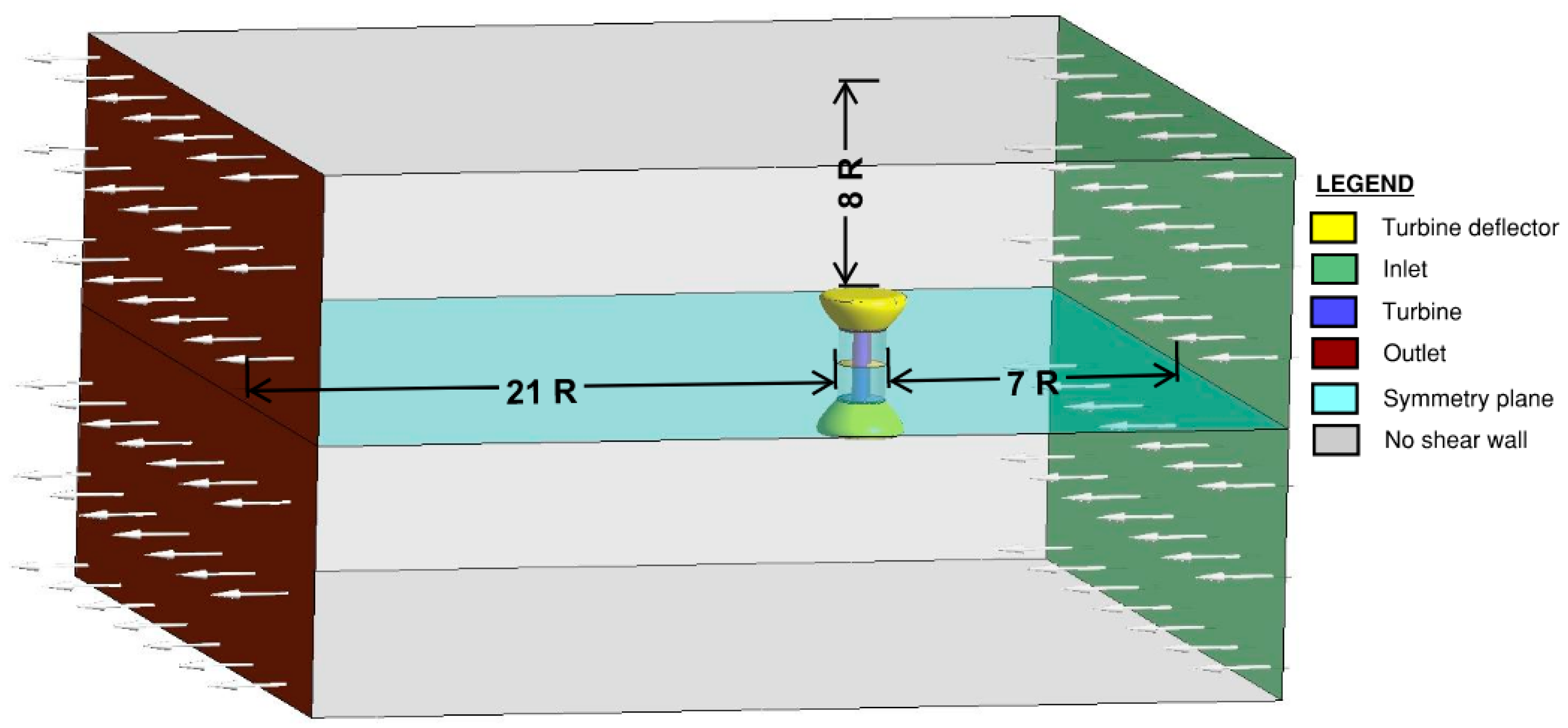
2.1. Numerical Model

The present study is based on a transient three-dimensional CFD simulation. The geometry of the urban wind turbine was created using ANSYS 2020 R2 DesignModeler© software. The numerical method used in this work was developed in a previous study [7].
The system involves rotating parts and fixed parts which is a challenge in CFD simulations. Techniques such as MRF (mixed reference frame) are computationally reasonable but cannot predict the average torque through a single revolution. The sliding mesh method is adapted to that application but is very expensive in terms of resources and time. The number of cases and turbine rotational velocities per deflector required a thorough study on the computational time requirements. The whole domain is divided into a stationary fixed domain which contains the deflector and a rotating one. The contact region between those two domains is treated as an interface. The stationary subdomain is obtained by extracting the rotating part and the designed deflector. The rotating subdomain is then modeled and added as a separate cylinder, as seen in Figure 1. The dimensions of the computational domain shown in Figure 1 were chosen following the recommendations of El-Askary et al. [4]. Boundary conditions involve a shear-free wall on the outer walls of the stationary domain to avoid nonrealistic shear wall stress diffusion into the rotating domain. This wall acts only as a container by preventing the airflow from exiting the stationary domain. The turbine end plates, deflector, and blade are no-slip walls. A constant velocity of 7 m/s with a turbulence intensity of 5% are imposed at the inlet and a pressure-outlet condition (constant atmospheric pressure) is imposed at the outlet (see Figure 1).
Reynolds-averaged turbulence approaches using two equation models are widely used for wind turbines CFD simulations. Commonly used models such as the realizable k-ε model or the K-ω SST model showed promising results compared to the available experimental data. Four equation models such as transition TSST are also found in the literature. In this study, we adopted the K-ω SST two-equation turbulence model [8,9,10,11,12,13]. In the numerical analysis, the minimum y+ dimensionless value was obtained at an average of 2.
To evaluate the average torque developed over the whole operating range, five turbine rotational velocities corresponding to five tip-speed ratios λ were imposed on each case. In order to avoid divergence, Svetlana et al. [14] advised to proceed with small timesteps corresponding to 0.5°–1° increments for each λ; however, this would result in an excessive computation time, especially given the large number of simulations performed in the present study. After optimizing the simulation time by fine-tuning the mesh quality, number of cells, and—most importantly—selecting the optimal numerical solvers, the selected time step for each λ varied between 3° and 4°. Stabilization of the average torque was achieved after 4 complete revolutions. The comparison of these values under identical conditions on all 15 deflector designs revealed significant impact of the geometrical shapes of the deflector on the final turbine performance.

2.2. Simulation Settings
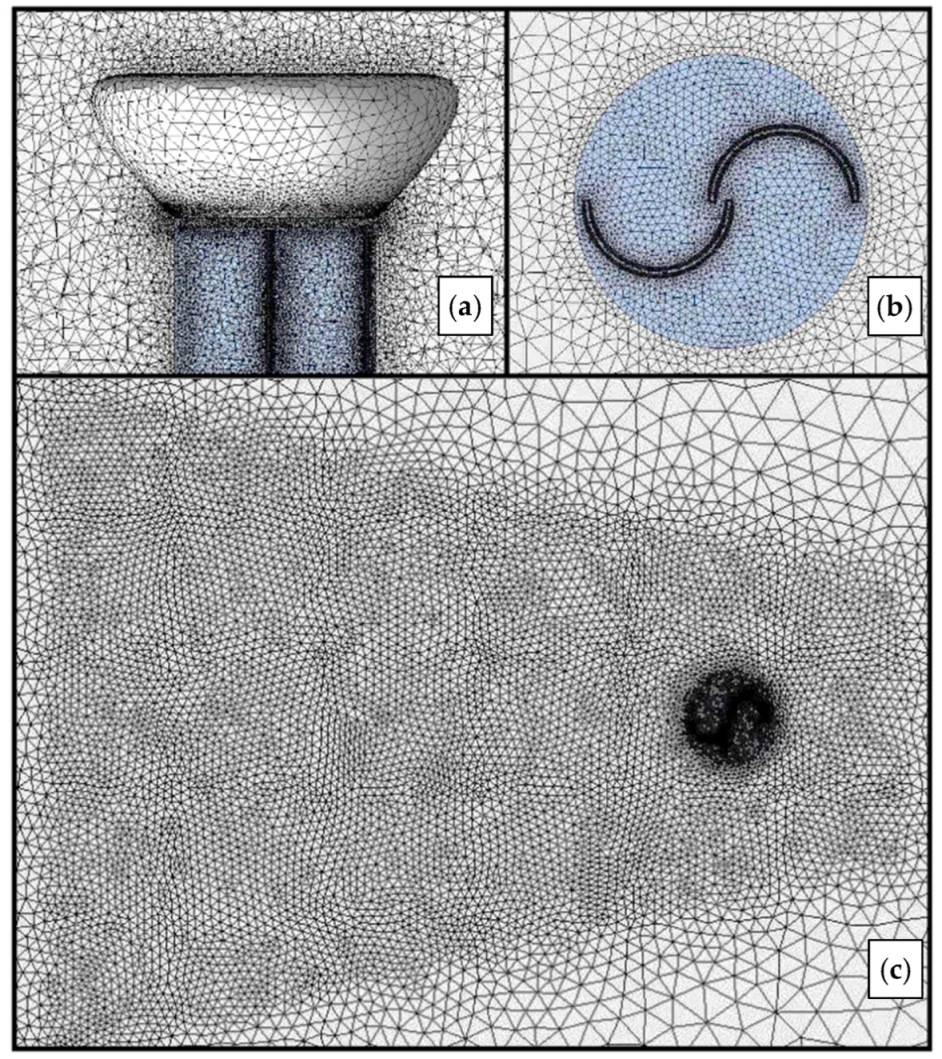
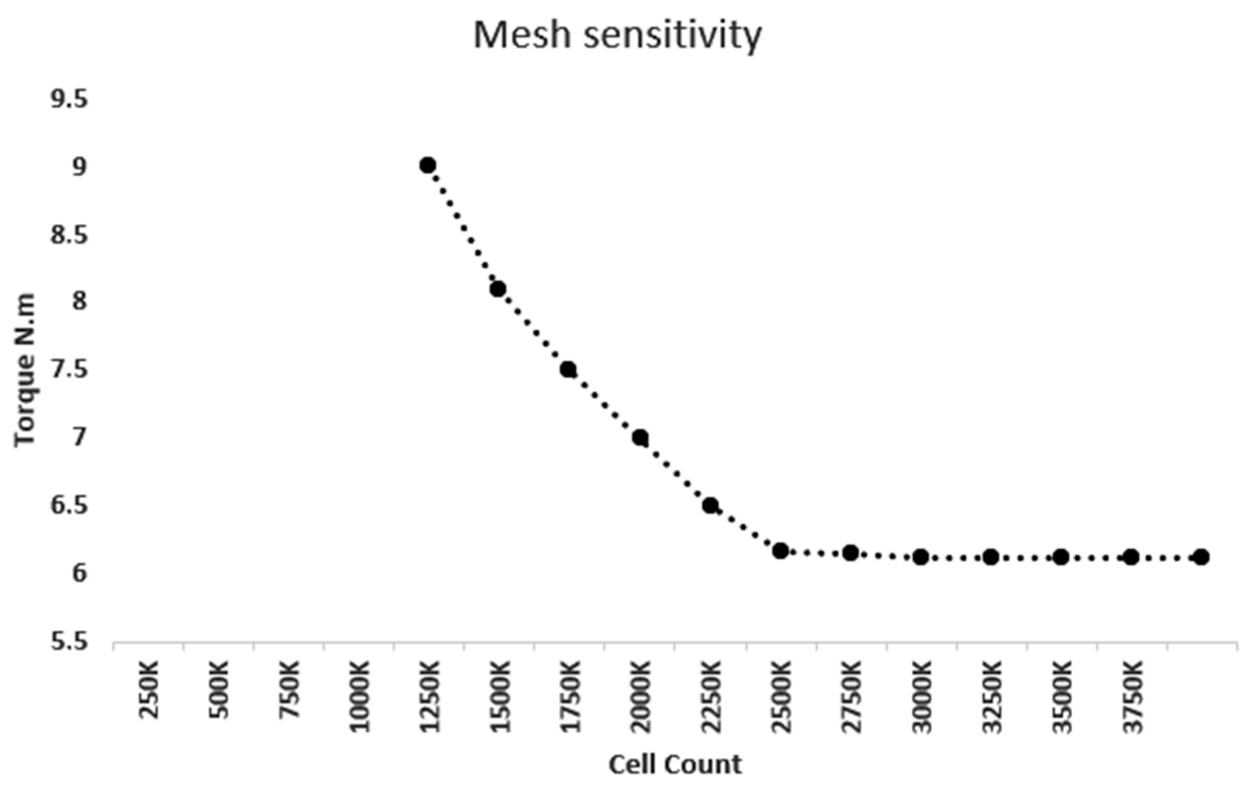
2.2.1. Meshing

To reduce the computational expenses and the simulation time, a symmetry plane was added, as seen in Figure 1. Two symmetry faces were included in the model, with one in the stationary domain and one in the rotating domain, the latter being used to induce identical rotation in the symmetric volume. This configuration was validated by comparing the results to those obtained on whole domain simulations. Figure 2 is used to illustrate the form and size of the unstructured mesh around and over the turbine. To ensure the accuracy of the numerical analysis, the mesh independence study reported in Figure 3 was first carried out. The average torque according to the different mesh size for spline 1 was stabilized for 2.2 million cells. As seen in the Figure 3, the variation of the average torque was held at 4% for the 2.2. It should also be noted that the simulation time was almost 3 times longer with a 4 million cell mesh, which was clearly not feasible in the frame of the study. The selected mesh was therefore a compromise between computational cost and accuracy. The unstructured mesh was generated using ANSYS 2020 R2 meshing software. It consists of about 2.5 million tetrahedral cells regardless of the case studied.
Downstream of the rotor, the mesh was refined to capture wake vortices (see Figure 2a). In addition, an inflation mesh consisting of 18 layers of prismatic elements around the blades was created around each airfoil to reach acceptable y+ values. The dimensionless height of the first mesh node adjacent to wall y+ has a major impact on the simulation results and, most importantly, on the final monitored parameter. Indeed, the torque produced around the axis of the wind turbine imposes a fine resolution of the viscous sublayer, hence the need for a y+ value below 5 on the blades. This optimized mesh made it possible to achieve an average value of y+ of 2 on the turbine surface.

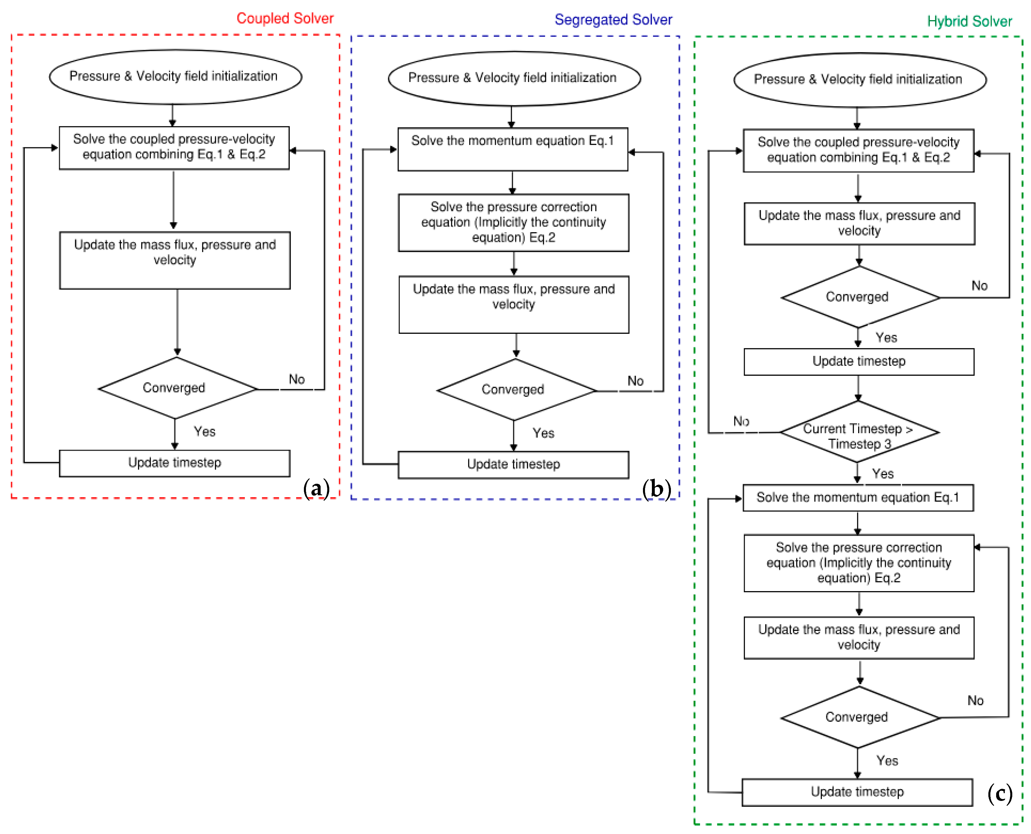
2.2.2. Hybrid Pressure-Based Solver Approach

ANSYS Fluent 2020 R2 software was used in the present study for transient 3D CFD simulations. The URANS momentum and continuity equations are written as follow:
t ρ u i ¯ + x j ρ u i ¯   u j ¯ = p x i + x j μ u i ¯ x j + u j ¯ x i 2 3 δ i j u k ¯ u k + x j ρ u i u j ¯
ρ t + x i ρ u i ¯ = 0
where u i ¯ and u i represent the mean and fluctuating velocity components (i = 1,2,3), ρ is the fluid density, p is the pressure, and the function δ i j is defined as δ i j = 1   i = j 0 ,   i j . The Reynolds stress term ρ u i u j ¯ is modeled by the K-ω SST two-equation turbulence model, which was found to be the most appropriate for wind turbine applications.

Pressure-Based Solvers

The pressure-based solver has been traditionally used for incompressible ( ρ = constant ) or mildly compressible flows [15]. The density-based approach, on the other hand, was originally designed for high-speed compressible flows. In urban wind turbine application, the flow is considered incompressible given the ambient atmospheric pressure. In incompressible flows, the density is fixed and pressure independent. Consequently, the coupling between pressure and velocity introduces a constraint in the solution of the flow field. In simple terms, we should supply the correct pressure field in the momentum Equation (1) so that the resulting velocity field also satisfies the continuity Equation (2). It is then obvious that the resolution of the linear discretized equations using the finite volume method is performed iteratively [16,17].

Segregated Solvers

This algorithm is essentially a guess-and-correct procedure. In the first place, a guessed pressure field is used to solve the momentum Equation (1) with only velocities unknown. A pressure correction equation derived from both continuity and momentum equations is solved, which in turn is used to update the pressure and velocity fields. In a nutshell, each cell is tested with the initially calculated velocities: if the continuity equation is not satisfied and there is, for instance, more mass flowing into the cell than out of it, then the pressure in the cell must be increased relative to its neighboring cells [18].

Pressure Coupled Solvers

Unlike the segregated algorithm described above, the pressure-based coupled algorithm solves a coupled system of equations comprising the momentum equations and the pressure-based continuity equation. Thus, in the coupled algorithm, the guess-and-correct procedure is replaced by a single step, in which the coupled system of equations is solved. Since the momentum and continuity equations are solved in a closely coupled manner, the rate of solution convergence significantly improves when compared to the segregated algorithm. However, the memory requirement increases by a factor ranging from 1.5 to 2 compared to the segregated algorithm since the discrete system of all momentum and pressure-based continuity equations must be stored in the memory when solving for the velocity and pressure fields (rather than just a single equation, as is the case with the segregated algorithm) [19,20]. For transient flows, the coupled algorithm enhances convergence and can be used when the quality of the mesh is relatively poor and/or relatively large time steps are used. In the present case, many transient 3D CFD simulations are performed, which is very expensive computationally. To reduce the simulation time, mesh count was reduced and so was the mesh quality. On the other hand, large timesteps (4° instead of 0.5°) were also used to optimize the simulation duration, which require the use of a pressure-based coupled solver to avoid divergence. Based on initialized pressure and velocity field, the segregated solver tends to diverge with relatively bad mesh quality and large timesteps, which happened in our case. So, a hybrid procedure based on solving the first three steps in a coupled solver and switching to segregated one once the pressure field and the velocity field are harmonized was explored. This hybrid scheme reduced the simulation time by 40% while avoiding divergence when solving. Figure 4 presents the algorithms of the three solvers.

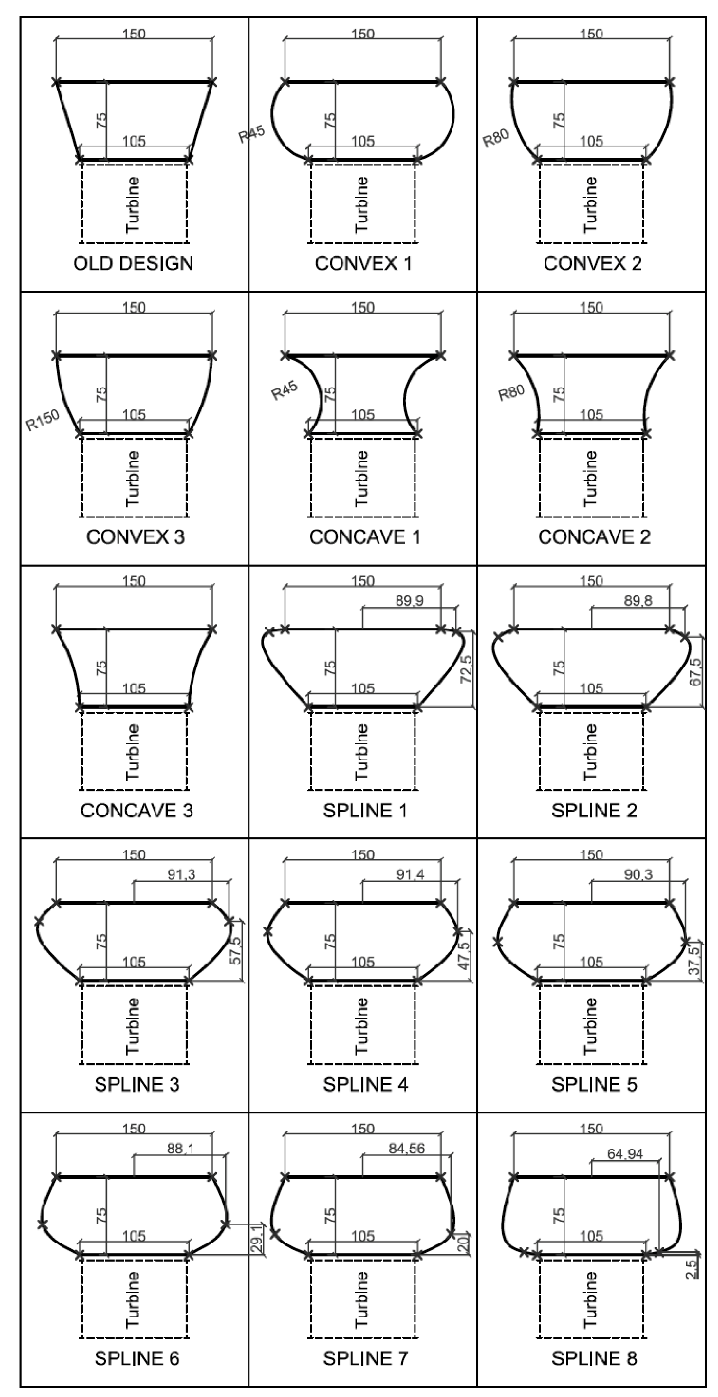
2.3. Key Features of the Evaluated Deflectors

The deflector used as a benchmark in this study is the one developed by Aboujaoude et al. [7] in Figure 5, referred to as the “old design”. The profile consists of a three-dimensional truncated cone. Although the mounting system of the deflectors is not represented, it is thought to be completely dissociated and independent from the turbine structure. To study the geometric shape impact of the deflector faces on the turbine performance, three concave-, three convex-, and eight spline-shaped deflectors cases are proposed and presented in Figure 5. All the spline cases have the same deflector volume, which equates the volume of the convex 1 case. All 3D transient CFD simulation runs are performed by imposing 5 different turbine rotation speeds defined below by the tip speed ratio λ. The developed torque curves and averages through the different velocities are monitored and stored for comparison purposes. On the other hand, the total force combining the drag and the lift applied on each deflector is also monitored to study the impact of the geometrical shapes on the structural fatigue and stability.

3. Results and Discussion

To compare the performance impact of the fifteen studied deflectors, the torque developed on the wind turbine was monitored on five different turbine rotational velocities or tip speed ratios. In transient turbine simulations, the torque is periodic and depends on the angular position. The average torque per period is the main parameter monitored and is reported in Table 2 for each simulation. A positive average torque for an ideal turbine (no friction losses) would correspond to an acceleration potential, and a negative one corresponds to a deceleration potential, while a steady-state turbine with a null torque average would be able to maintain constant velocity. Figure 6 depicts the periodic average torque as a function of the tip speed ratio as well as the comparison between the force acting on the deflector of the former design and the spline 1 respectively. The spline 1 case displays the best performance through all rotation speeds and tip speed ratios. For the Savonius turbines, the most favorable tip speed ratios lie between 0.8 and 1.0. Favorably, it is in this region that the improvement is at its best, lying between 27% and 50% of average torque increase, as shown in Figure 6a. Figure 7a–c shows the velocity contours maps displayed in the z direction of the spline 1, spline 8, and old design cases. The cross-section is located at z = 0.74 m, which is directly under the end plate of the turbine. In addition, Figure 8g–i depicts the streamlines colored by velocity for spline 1, spline 8 and former design for a tip speed ratio of 0.8. The streamlines plotted in Figure 8g–i show higher suction magnitude for the spline 1, which diverts more incoming airflow from the inlet side to the rotor domain. The spline 1 case, even though it is geometrically close to spline 2 and spline 3, has average torque results that are still significantly higher, especially for high speeds, which proves the high sensitivity of the geometrical shapes on the turbine performance. On the other hand, the structural stability of the deflector is an important parameter for operating wind turbines. High induced forces by wind and turbine rotation could result in structural defects in the deflector. Figure 6b monitors the resulting force on the deflector for both the former and spline 1 design for a tip speed ratio of 0.8. It is observed that the resulting average force on the old deflector design is 8.5% higher than that on spline 1, but most importantly, force variation in a revolution is reduced by 60% in the spline 1 design, which reduces the structural fatigue.
The velocity contours maps of Figure 7 illustrate the diverting capacity of each of the deflectors. Indeed, at the inlet side of the rotor, the negative value contours (yellow, green, and blue) show the extents of the wind deviated down to the turbine. As seen in Figure 7a–c, the deflection capacity of the three cases are measured as negative velocity areas at the inlet of the turbine, and it is clear that the spline 1 case deflector has the best performance, followed by spline 8 and then the old design case. Figure 8a–c shows the velocity contours and, more precisely, the flow separation point, which has a key role for fluid flows around obstacles. The flow separation in the spline 8 and old design cases occurs upstream the turbine in contrast to the spline 1 case, where we see separation downstream the turbine. Figure 8d–f shows the recirculation zones and eddies downstream the turbines for all cases. On the other hand, it also shows the eddies created on the top and downstream the deflector for spline 8 and old design configurations. The results show us that the recirculation zones generate a local decrease in velocity. The recirculation zones are particularly visible in Figure 8d–f downstream of the turbine but also above the deflector for the spline 8 and the old design deflector. The results show us that the flow is strongly decelerated downstream of the separation point, which is particularly noticeable for the spline 8 and the old design deflector. To appreciate and compare the deflector convergence capacities in the simulated cases, streamlines plotted from the interface in backward and forward schemes seem to be an appropriate parameter. Indeed, being a line that is tangential to the instantaneous velocity direction, it helps visualize the flow or the motion of a small, marked element of fluid. A sensitivity test was carried out on the number of points specified on the rotating interface, and beyond 500 points, the measured height defined in Figure 8g–i is stabilized. This measured height also shows an increase in the diverting capacity when using the spline 1 deflector as reflected also in the averaged torque results shown in Table 2. Considering the spline 1 and spline 2 cases and as shown in Figure 5, the geometrical shapes appear to be quite similar, while the spline 2 and spline 8 cases are considerably different. However, when comparing the performances through the average torques, spline 1 has greater performances, while spline 2 and spline 8 perform quite similarly. This relays the importance of thorough optimization of wind deflector shapes where small geometrical variations could imply substantial gains. Finally, the air flows more easily along the spline 1, which has a rounded edge. This deflector shape allows the airflow to be directed favorably toward the turbine, which consequently increases the torque. Figure 8 suggests a close link between aerodynamics and cyclic force variation. These results suggest that the more aerodynamic the shape of the deflector, the lower the drag forces will be, resulting in less structural fatigue.

4. Conclusions

In this work, diverse axisymmetric deflector shape variations associated with a Savonius wind turbine were studied. This type of deflector has the advantage of being unidirectional while being fixed, thus avoiding all the drawback of wind reorienting mechanisms. This unidirectional feature is very relevant in the urban environment where the main wind features are the increased turbulence intensities and fast wind direction variations. Seventy 3D URANS CFD simulations were run, and the mean torque on the turbine axis was monitored for performance comparison. The spline 1 case showed an increased performance of 27% at λ = 0.8 and 50% at λ = 1.0, this region being typically the maximum power zone of Savonius. On the other hand, the wind forces applied on the deflectors were monitored and compared. Lower wind-induced forces were captured on the spline 1 case compared to the former design. A force variation of 2 N was recorded for the spline 1 deflector versus 3.2 N for the old design per revolution (0.56 s) at λ = 0.8, which significantly reduces the structural fatigue of the wind turbine. A hybrid numerical solver combining a coupled pressure solver and segregated solver was presented. This new numerical resolution approach reduced the simulation time by 40% while avoiding resolution divergence. Future studies will focus on integrating axisymmetric deflector into Darrieus vertical axis wind turbines.

Author Contributions

Methodology, H.A. and S.M.; Validation, F.B. (Fabien Bogard) and F.B. (Fabien Beaumont); Formal analysis, H.A., S.M. and G.P.; Investigation, H.A.; Resources, F.B. (Fabien Bogard); Writing—original draft, H.A.; Writing—review & editing, F.B. (Fabien Beaumont) and G.P.; Supervision, F.B. (Fabien Bogard). All authors have read and agreed to the published version of the manuscript.

Funding

This research received no external funding.

Data Availability Statement

The data presented in this study are available on request from the corresponding author.

Conflicts of Interest

The authors declare no conflict of interest.

References

  1. Alexander, A.J.; Holownia, B.P. Wind tunnel tests on a savonius rotor. J. Wind Eng. Ind. Aerodyn. 1978, 3, 343–351. [Google Scholar] [CrossRef]
  2. Altan, B.D.; Atılgan, M. A study on increasing the performance of Savonius wind rotors. J. Mech. Sci. Technol. 2012, 26, 1493–1499. [Google Scholar] [CrossRef]
  3. Mohamed, M.H.; Janiga, G.; Pap, E.; Thévenin, D. Optimization of Savonius turbines using an obstacle shielding the returning blade. Renew. Energy 2010, 35, 2618–2626. [Google Scholar] [CrossRef]
  4. Golecha, K.; Eldho, T.I.; Prabhu, S.V. Influence of the deflector plate on the performance of modified Savonius water turbine. Appl. Energy 2011, 88, 3207–3217. [Google Scholar] [CrossRef]
  5. El-Askary, W.A.; Nasef, M.H.; Abd El-Hamid, A.A.; Gad, H.E. Harvesting wind energy for improving performance of Savonius rotor. J. Wind Eng. Ind. Aerodyn. 2015, 139, 8–15. [Google Scholar] [CrossRef]
  6. Tartuferi, M.; D’Alessandro, V.; Montelpare, S.; Ricci, R. Enhancement of Savonius wind rotor aerodynamic performance: A computational study of new blade shapes and curtain systems. Energy 2015, 79, 371–384. [Google Scholar] [CrossRef]
  7. Aboujaoude, H.; Beaumont, F.; Murer, S.; Polidori, G.; Bogard, F. Aerodynamic performance enhancement of a Savonius wind turbine using an axisymmetric deflector. J. Wind Eng. Ind. Aerodyn. 2022, 220, 104882. [Google Scholar] [CrossRef]
  8. Rezaeiha, A.; Montazeri, H.; Blocken, B. On the accuracy of turbulence models for CFD simulations of vertical axis wind turbines. Energy 2019, 180, 838–857. [Google Scholar] [CrossRef]
  9. Ghazalla, R.A.; Mohamed, M.H.; Hafiz, A.A. Synergistic analysis of a Darrieus wind turbine using computational fluid dynamics. Energy 2019, 189, 116214. [Google Scholar] [CrossRef]
  10. Alom, N.; Saha, U.K.; Dean, A.X. In the quest of an appropriate turbulence model for analyzing the aerodynamics of a conventional Savonius (S-type) wind rotor. J. Renew. Sustain. Energy 2021, 13, 023313. [Google Scholar] [CrossRef]
  11. Shaheen, M.; El-Sayed, M.; Abdallah, S. Numerical study of two-bucket Savonius wind turbine cluster. J. Wind Eng. Ind. Aerod. 2015, 137, 78–89. [Google Scholar] [CrossRef]
  12. Mohamed, H.; Thevenin, D. Performance optimization of a Savonius turbine considering different shapes for frontal guiding plates. In Proceedings of the 10th International Congress of Fluid Dynamics, Stella Di Mare Sea Club Hotel, Ain Soukhna, Red Sea, Egypt, 16–19 December 2010; Volume 16, p. 19. [Google Scholar]
  13. Kumar, A. Performance analysis of a Savonius hydrokinetic turbine having twisted blades. Renew. Energy 2017, 113, 461–478. [Google Scholar] [CrossRef]
  14. Marmutova, S. Performance of a Savonius Wind Turbine in Urban Sites Using CFD Analysis. Ph.D. Thesis, University of VAASA, Vaasa, Finland, 2016. [Google Scholar]
  15. Mangani, L.; Darwish, M.; Moukalled, F. Development of a pressure-based coupled CFD solver for turbulent and compressible flows in turbomachinery applications. In Proceedings of the ASME Turbo Expo 2014, Düsseldorf, Germany, 16–20 June 2014; p. V02BT39A019. [Google Scholar]
  16. ANSYS. Fluent User’s Guide 2019R1; 26.1 Overview of Using the Solver; ANSYS: Canonsburg, PA, USA, 2019. [Google Scholar]
  17. Acharya, S.; Baliga, B.R.; Karki, K.; Murthy, J.Y.; Prakash, C.; Vanka, S.P. Pressure-Based Finite-Volume Methods in Computational Fluid Dynamics. J. Heat Transf. 2007, 129, 407–424. [Google Scholar] [CrossRef]
  18. Ding, P.; Sun, D.L. A pressure-based segregated solver for incompressible flow on unstructured grids. Numer. Heat Transf. 2014, 64, 460–474. [Google Scholar] [CrossRef]
  19. Biesinger, T.; Cornelius, C.; Rube, C.; Braune, A.; Campregher, R.; Godin, P.G.; Schmid, G.; Zori, L. Unsteady CFD Methods in a Commercial Solver for Turbomachinery Applications. In Proceedings of the ASME Turbo Expo 2010, Glasgow, UK, 14–18 June 2010; pp. 2441–2452. [Google Scholar] [CrossRef]
  20. Galindo, J.; Hoyas, S.; Fajardo, P.; Navarro, R. Set-Up Analysis and Optimization of CFD Simulations for Radial Turbines. Eng. Appl. Comput. Fluid Mech. 2013, 7, 441–460. [Google Scholar] [CrossRef] [Green Version]
Figure 1. Domain dimensions and boundary conditions.
Energies 16 00909 g001
Figure 2. Unstructured mesh details. (a) Surface mesh on the turbine and in the median plane of the computational domain; (b) representation of the mesh in a horizontal plane around the turbine; (c) overview of the mesh around the turbine.
Energies 16 00909 g002
Figure 3. Mesh sensitivity graph.
Energies 16 00909 g003
Figure 4. Solver’s algorithms. (a) Coupled solver; (b) segregated solver; (c) hybrid solver.
Energies 16 00909 g004
Figure 5. Axisymmetric deflector geometrical shapes and dimensions.
Energies 16 00909 g005
Figure 6. (a) Periodic average torque of the former design (continuous black line) and the spline 1 case (dotted red line) for different values of λ; (b) comparison between the force acting on the deflector of the former design (black continuous line) and the spline 1 (red continuous line) at λ = 0.8.
Energies 16 00909 g006
Figure 7. Velocity in the z direction at z = 0.74 m at λ = 0.8. (a) Spline 1 case; (b) spline 8 case; (c) former design.
Energies 16 00909 g007
Figure 8. Topology of the flow in a median plane. (a) average velocity of spline 1, λ = 0.8; (b) average velocity of spline 8, λ = 0.8; (c) average velocity of former design, λ = 0.8; (d) velocity vectors of spline 1, λ = 0.8; (e) velocity vectors of spline 8, λ = 0.8; (f) velocity vectors of former design, λ = 0.8; (g) streamlines colored by velocity for spline 1, λ = 0.8; (h) streamlines colored by velocity for spline 8, λ = 0.8; (i) f for former design, λ = 0.8.
Energies 16 00909 g008
Table 1. Turbine characteristics and main dimensions.
Turbine Dimensions
Blades Number Blade DiameterTurbine HeightEndplate
Diameter
Endplate HeightDimensionless Gap Width e/d
20.5 m1.5 m1.0 m0.01 m0.1
Table 2. Periodic averaged torque developed around the turbine axis per deflector case and per tip speed ratio.
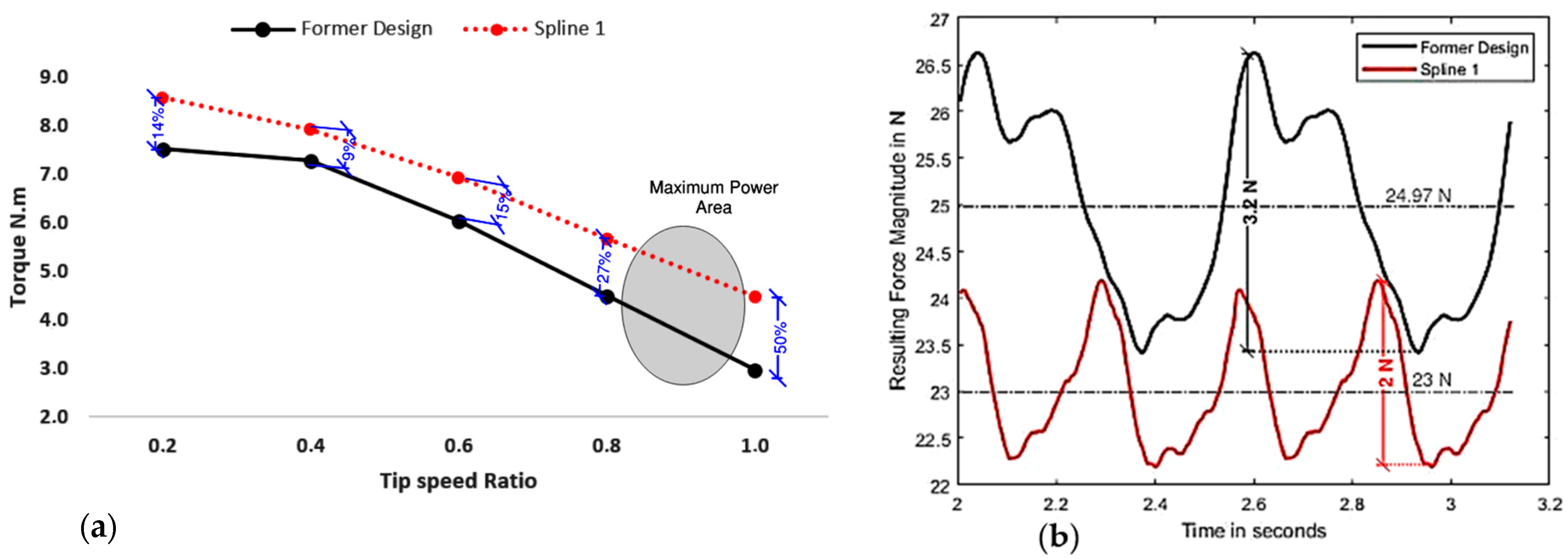
Torque Developed around Turbine Axis in N.m
Tip   Speed   Ratio   λ 0.20.40.60.81.0
Former Design7.57.36.04.53.0
Convex 17.87.35.14.73.4
Convex 27.77.15.04.53.2
Convex 37.46.94.84.63.2
Concave 16.86.84.74.43.2
Concave 26.96.94.74.43.1
Concave 37.06.94.84.43.1
Spline 18.67.96.95.73.2
Spline 27.97.46.34.84.5
Spline 38.47.56.34.73.3
Spline 48.37.56.24.83.1
Spline 58.07.46.24.83.1
Spline 68.57.56.24.73.1
Spline 78.37.46.14.73.1
Spline 88.27.56.14.83.1
Disclaimer/Publisher’s Note: The statements, opinions and data contained in all publications are solely those of the individual author(s) and contributor(s) and not of MDPI and/or the editor(s). MDPI and/or the editor(s) disclaim responsibility for any injury to people or property resulting from any ideas, methods, instructions or products referred to in the content.

