Article

Design of Variable Pitch Control Method for Floating Wind Turbine

College of Electrical Engineering, Xinjiang University, Engineering Research Center for Renewable Energy Generation & Grid Control, Urumqi 830017, China
*
Author to whom correspondence should be addressed.
Energies 2023, 16(2), 821; https://doi.org/10.3390/en16020821
Submission received: 29 November 2022 / Revised: 26 December 2022 / Accepted: 7 January 2023 / Published: 11 January 2023

Abstract

:
Because of the randomness of wind speed and the nonlinearity of the dynamic equation of variable pitch control, it is difficult to establish an accurate dynamic equation of variable pitch of floating fan. In view of this situation, this paper takes the 5 MW floating wind turbine of the NREL (National Renewable Energy Laboratory) as the research object, establishes the dynamic equation under the basic control of FAST, uses the L-M (nonlinear least square method) to identify the dynamic parameters of the system and obtains the dynamic model of the floating fan under variable pitch stability control. Compared with the output of FAST in the same case, the accuracy of the control model is verified; the FAST base pitch control adopts PI control, but the effect of FAST base control is relatively poor. This paper proposes a disturbance-adaptive pitch control method based on fractional PID feedback; the results show that compared with the FAST base pitch control, the control method is more suitable for variable pitch control of a floating wind turbine. The generating power is more stable, the overshoot of generating power is smaller and the fluctuation of wind speed is smaller. Except for surge and heave, the fluctuation of the other four degrees of the freedom of the floating wind turbine platform is reduced, making it more suitable for the variable pitch control of the floating wind turbine.

1. Introduction

The value of wind energy is inexhaustible; as a clean energy, people are paying more and more attention to it. Offshore wind power resources are abundant, but the utilization rate of offshore wind turbines is relatively low at present, mainly because offshore wind turbines are affected by a complex environment. When the wind speed reaches a level high enough for sustainable utilization of wind energy, the greater the load; a change in wind speed will have a great impact on the performance of the fan. The research method of variable pitch control of wind turbines is relatively mature [1,2,3]. Wind turbine pitch control is generally divided into linear control and nonlinear control. Linear control is used to obtain a linear model [4]. Nonlinear control refers to a nonlinear model [5,6,7,8]. For variable pitch control of the wind turbine, experts at home and abroad have carried out the following research: Yin et al. [9] proposed a new type of electro-hydraulic servo variable pitch system. Aghainezhad et al. [10] proposed an adaptive fractional order nonsingular fast terminal sliding mode controller based on a single pitch control strategy based on a simplified mathematical model of a wind turbine. However, the optimal parameters of sliding mode control are often difficult to find. For the nonlinear system of wind turbine, Civelek et al. [11] adopted a fuzzy pitch controller based on an improved genetic algorithm to ensure the safe operation and stable output power of wind turbines. In [12,13], a fuzzy control of a wind turbine is presented. Although the control objectives are different, under the framework of fuzzy control and PI control, better target tracking can be achieved. However, the optimization of fractional order parameters depends on empirical methods. Landaluze et al. [14] proposed a multivariable and multi-objective control strategy for the variable pitch control of a floating wind turbine based on the reduced order design of an H∞ controller. Namik et al. [15,16] proposed a linear parameter time-varying control (LPVC) method and applied it to the variable pitch control of offshore floating wind turbines. The output power and motion performance with or without LPVC control werere analyzed, but the control underwent no obvious change. Ahmed Lasheen et al. [17] introduced the fuzzy prediction algorithm into the variable pitch control of wind turbines, adjusted the pitch angle online and obtained stable power output; however, the effect is not obvious. The predictive control algorithm must consider the constraints; when it is used in this nonlinear system, there is a problem in that the system’s stability cannot be judged. With reference to [18], an independent pitch control scheme based on an RBF neural network is proposed. This scheme uses the off-line self-learning characteristics of an RBF neural network to obtain the pitch angle for pitch control. Its obvious disadvantage is that the weight and center of neural network cannot be adjusted online, resulting in poor dynamic performance of the system. In order to maintain the stability of the floating structure under the combined action of wind and wave, Lackner [19] proposed a method to control the total blade pitch, and proposed an independent variable pitch controller (IPC) to reduce platform and blade loads. Jiao et al. [20] proposed a pitch angle controller based on effective wind speed estimation and uncertain disturbance estimation. The results show that this method has better control performance than the traditional adaptive proportional integral pitch angle control. Karad [21] proposed a fractional order PID controller for pitch angle control of wind turbines. However, there is often no good optimization method for the control parameters.
In order to solve the above problems, a nonlinear model of variable pitch control is established in this paper. Based on the established model, an adaptive controller with fractional-order PID state feedback is designed, and its parameters are optimized by genetic algorithm. Compared with the FAST base control, the results show that the control method is more suitable for variable pitch control of floating wind turbines; the generating power is more stable, the overshoot of generating power is smaller and the fluctuation of wind speed is smaller. Except for surge and heave, the fluctuation of the other four degrees of the freedom of the floating wind turbine platform is reduced.

2. Main Parameters of Floating Wind Turbine

This paper takes the national laboratory OC4 semi-submersible wind turbine as the research object. The main parameters of OC4 semi-submersible wind turbine are shown in Table 1. The parameters of floating wind turbine are shown in Table 1, and the platform parameters of floating wind turbine are shown in Table 2.

3. Floating Wind Turbine Model

3.1. Establishment of Floating Wind Turbine Model

Aiming at the floating wind turbine, the dynamic state equation of the pitch angle is established.
{ Δ ω · = A Δ ω + B Δ β + B d Δ v c β · = Δ β r Δ β τ Δ p = K 1 Δ ω + K 2 Δ β
In the formula, where Δ w is the change of the speed of the generator, Δ β is the change of the pitch angle, Δ v c is the disturbance of the wind speed, Δ p is the change of generating power, β r is the reference value of pitch angle and τ is the time constant, respectively. The design method of PID pitch controller provided by FAST can be described thus: the difference signal between the actual speed and the expected value of the generator is used as the input to control the change of the pitch angle of the floating wind turbine, in order to achieve stable power output. The traditional PID controller has a feedback control structure. After the system error is transferred through the operation of proportion, integral and derivative, the error is applied to the system input again and the system output is controlled as required. The PID variable pitch controller for floating wind turbines can be described as follows:
β ( t ) = K P e ( t ) + K I 0 t e ( τ ) d τ + K D e · ( t )
where e ( t ) is the error signal, and K P , K I and K D are proportional, integral and differential coefficients, respectively. Through Laplace transform, we can obtain the following:
Δ β ( s ) = K P Δ ω ( s ) + K i Δ ω ( s ) s + K d s Δ ω ( s )
The inverse Laplace transformation of Equation (1) can be obtained:
Δ ω ( s ) s = A Δ ω ( s ) + B Δ β ( s ) + B d Δ v ( s )
The simplification of (3) and (4) can be obtained:
Δ ω ( s ) ( 1 B K d ) s 2 + ( A B K p ) s + ( B K i ) = s B d Δ v ( s )
In the formula, the values of K P , K I and K D are known in the formula, and the L-M method is adopted to identify the values of A, B and Bd. For the variation in generating power, the values of K 1 and K 2 can also be obtained using the L-M method, and the dynamic state equation of the system may be obtained.

3.2. Verification of Floating Wind Turbine Model

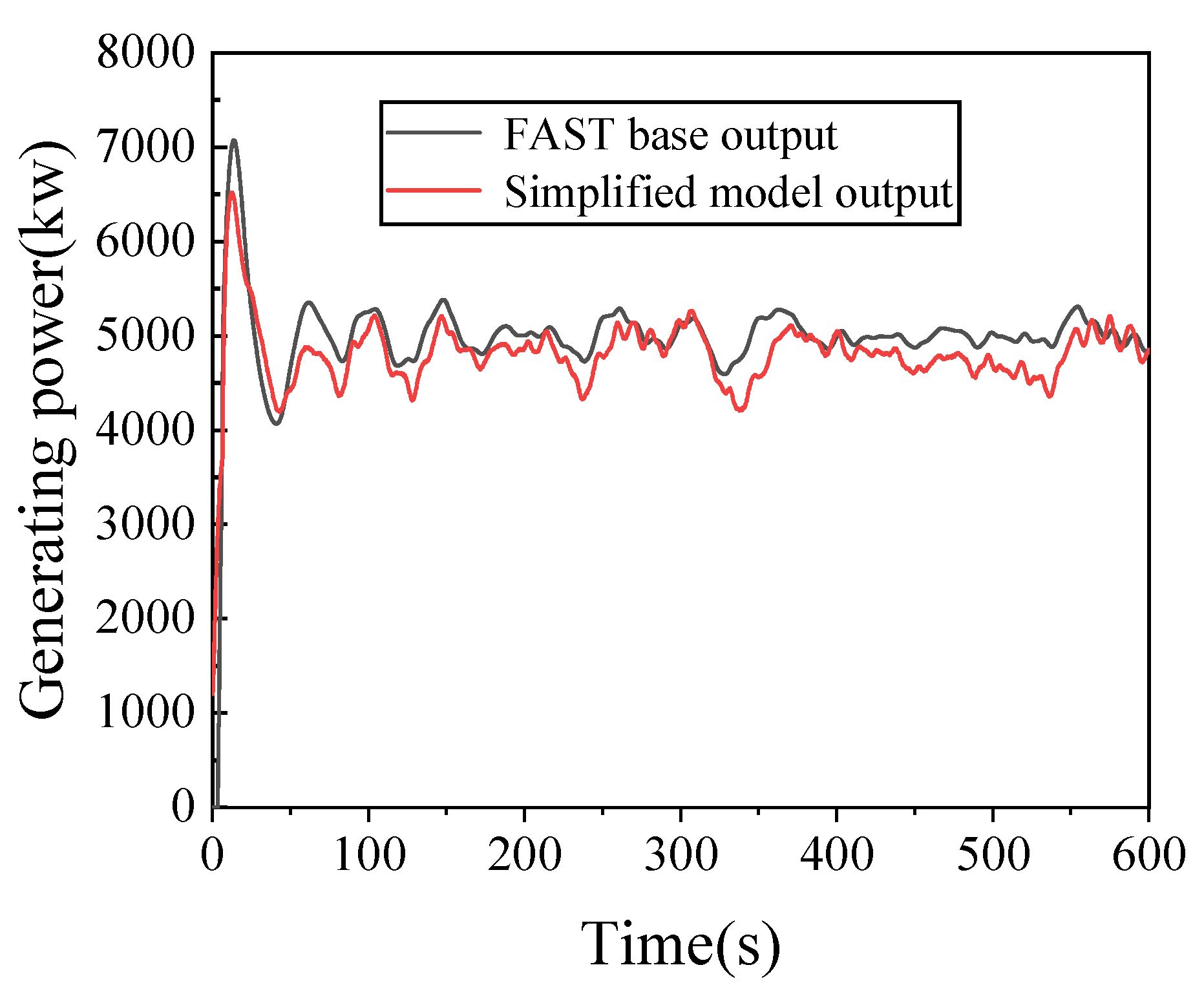
In order to verify the accuracy of the model established above, a wind speed of 18 m. s−1 is selected. Under the condition that the established system model is the same as the input of FAST, the output comparison is shown in Figure 1 and Figure 2, indicating that the established model is basically correct. It can be seen from the identified model that the generation power is related to the variation of rotational speed and pitch angle; the smaller the fluctuation of the wind wheel speed and pitch angle, the smaller and more stable the generating power fluctuation, Therefore, in the process of variable pitch control, as long as the fluctuation of pitch angle and speed becomes smaller, the generating power can be guaranteed to be stable.

3.3. Design of Disturbance Adaptive Control Based on Genetic Algorithm Fractional PID State Feedback

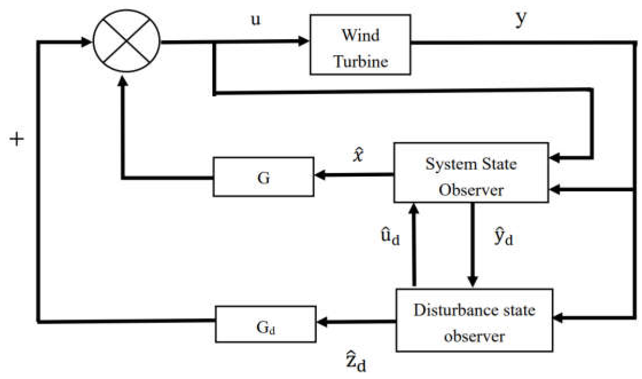
When the floating wind turbine is generating electricity, the adaptive interference control is used to eliminate the influence of the wind speed fluctuation, the pole assignment method is generally used for the feedback matrix, and the block diagram of the system state and disturbance adaptive control is shown in Figure 3. Although the pole assignment method can make the system stable, the control effect is not obvious. A disturbance adaptive pitch control, based on fractional order PID state feedback based on a genetic group algorithm is proposed.
The mathematical model of the state observer can be expressed as:
{ x · ( t ) = A x ( t ) + B u ( t ) + k ( y ( t ) y ( t ) ) y ( t ) = C x ( t )
The interference model can be expressed as:
{ z d · ( t ) = F z d ( t ) u d ( t ) = θ z d ( t )
In Equation (7), F and θ are known given matrices and their values are determined by the realization form of interference, where u d is the disturbance and z d is the component of the disturbance.
{ x · ( t ) = A x ( t ) + B u ( t ) + B d u d ( t ) + k x ( y ( t ) y ( t ) ) y ( t ) = C x ( t )
{ z d · ( t ) = F z d ( t ) + k d ( y ( t ) y ( t ) ) u d ( t ) = θ z d ( t )
After the interference model is introduced, the system state observer and the interference state observer can be expressed as:
e ( t ) · = ( A ¯ K C ¯ ) e ( t )
The error between the estimated value and the actual value of the system can be expressed as:
Among them A ¯ = [ A θ B d 0 F ] , C ¯ = [ C 0 ] , K ¯ = [ K x K d ] .
If the values of K P , K I and K D are properly selected, the system error can be changed to 0. Only by observing the value of A ¯ and C ¯ vector can the position of poles configured by the state observer ( A ¯ K C ¯ ) be in the complex plane, so that the response curve can quickly reach a stable state.
Considering the interference of the system, the system feedback rule can be obtained as follows:
u ( t ) = G x ( t ) + G d z d ( t )
According to the feedback rule, we can obtain:
x ( t ) · = ( A + B G ) x ( t ) + ( B G d + θ B d ) z d ( t )
The disturbance feedback matrix G d of the system can be calculated from the equation, and as long as ( B G d + θ B d ) is small enough, anti-jamming control can be accomplished. For a linear time-invariant system:
{ x · = A x + B u y = C x
The feedback control quantity combined with feedback control and PID control can be expressed:
G x ( t ) = x ( t ) ( K P + K I d s λ + K D s μ )
Combined with the pitch control of the floating fan:
G x ( t ) = K D Δ Ω · + ( K I s λ + K D s μ ) Δ Ω
For K P , K I , K D , λ and μ , a genetic algorithm is used to optimize the parameters.

3.4. PID Parameter Optimization Based on Genetic Algorithm

The genetic algorithm’s purpose is to introduce the biological evolutionary principle of “survival of the fittest” into the population formed by parameters so that the selected fitness value can be continuously copied, crossed and mutated in the genetics, in order to screen individuals, retain the high fitness value and form a new population. The new generation of the population inherits the information of the previous generation and is also better than the previous generation. The individual fitness value keeps getting higher and higher with each iteration until the requirements are met. The genetic algorithm is simple and can obtain the optimal solution.
The steps of genetic algorithm optimization are as follows.
  • Initialize the parameter population and set the population size, number of variables, genetic algebra, maximum number of iterations, crossover probability and mutation probability.
  • Set the parameter range of K P , K I , K D , λ , μ to (0.01, 0.2), (0.01, 0.2), (0.01, 1), (0, 1), (0, 1).
  • Use a binary encoding method for convenient genetic operation and obtaining the optimal solution after decoding.
  • Determine the individual evaluation method, namely the individual fitness function.
  • When the parameters are optimized and the fitness of individuals of the population is not equal to the average fitness, use the fitness allocation function to allocate the fitness. Use the selection operator, cross probability operator and mutation probability operator to operate the population and generate the next-generation population.
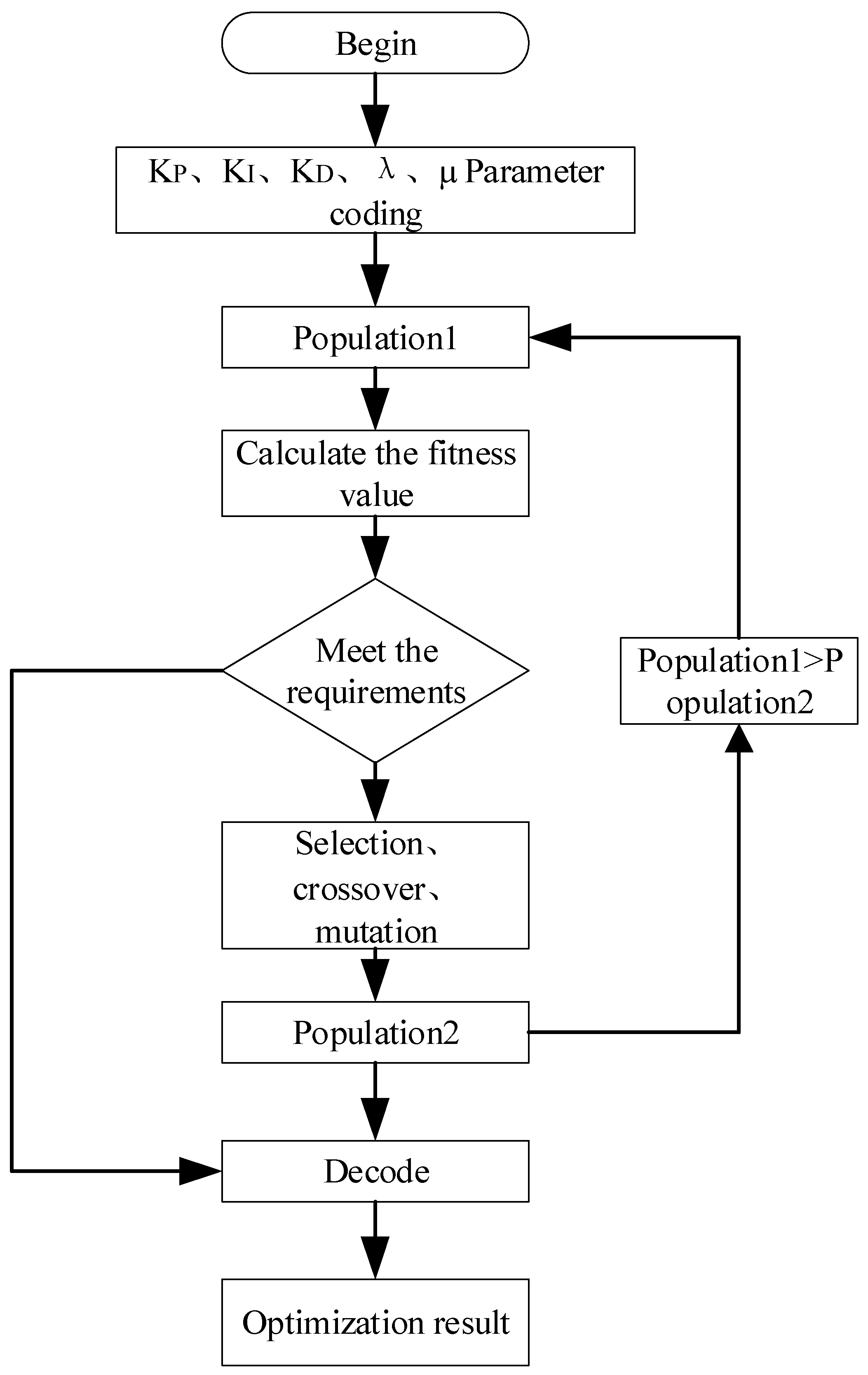
  • When the parameters converge or reach the target value, the optimal parameters of the system are obtained. The flow chart of the genetic algorithm optimization of PID parameters is shown in Figure 4.

3.5. Determination of Fitness Function

In order to meet the performance requirements of the floating fan pitch control, the absolute error time integration performance index is used as the minimum objective function for parameter selection. The square term of the control input is added to the objective function to prevent excessive control. The following formula is selected as the optimal index for parameter selection:
J = 0 ( w 1 | e ( t ) | + w 2 u 2 ( t ) + w 4 t s ) d t
The penalty function is used to avoid an overshoot of the system. When e(t) < 0, in this case, the optimal index is modified to:
J = 0 ( w 1 | e ( t ) | + w 2 u 2 ( t ) + w 3 | e ( t ) | + w 4 t s ) d t
where e ( t ) is the error of generator speed, u ( t ) is the change of pitch angle output by the controller, t s is the rise time, and w 1 , w 2 , w 3 , and w 4 are weighted values. Additionally, w 1 w 3 . The difference between w 1 and w 3 is too large, which can reduce the overshoot of the system. The values of, w 1 , w 2 , w 3 , w 4 are, 0.999, 0.001, 100, and 0.1, respectively. The optimization parameter is to obtain the minimum value of the objective function. The reciprocal of the objective function J is selected as the fitness function. The fitness function is shown in the following formula:
F = 1 / J

4. Simulation Experiment

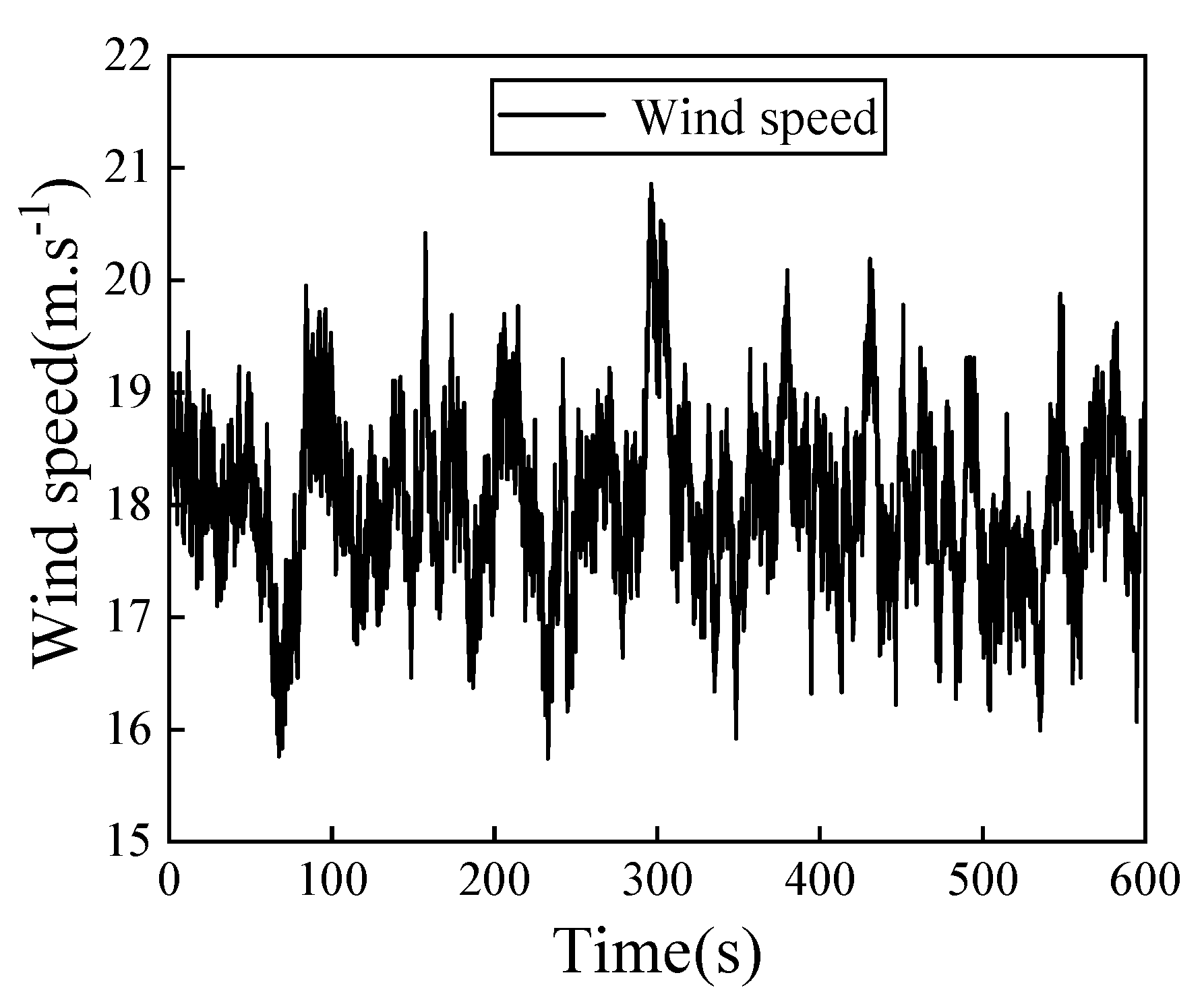
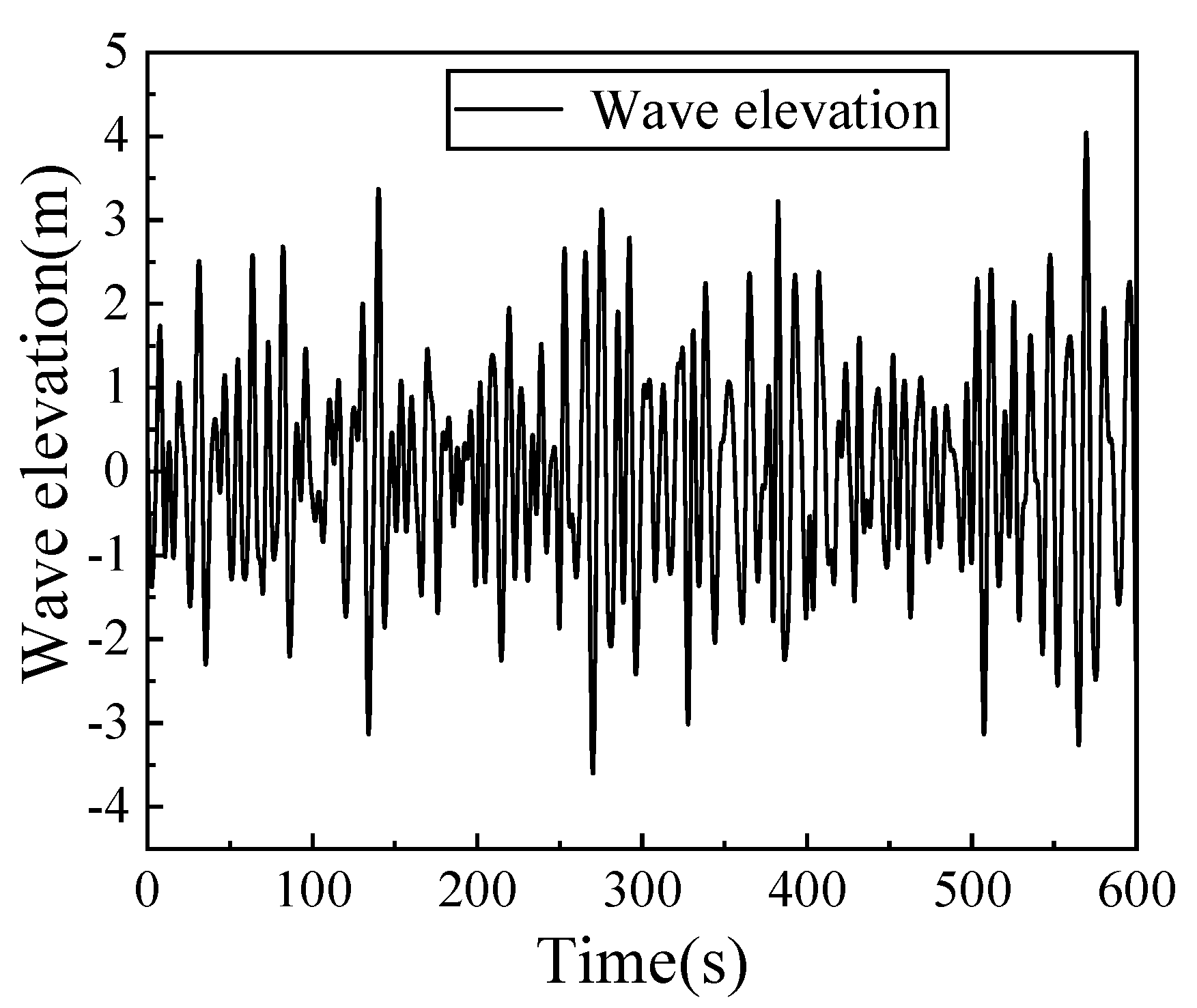
The wind spectrum uses the KAIMAL spectrum and the wave spectrum uses the PM spectrum. The wind speed and wave height are shown in Figure 5 and Figure 6. The wind speed is selected as 18 m.s−1, the wave elevation is 5 m, and under the same input condition, the contrast experiments are carried out under FAST basic variable pitch control and fractional order PID state feedback disturbance adaptive variable pitch control, respectively.

4.1. Study on Control Effect of Floating Wind Turbine

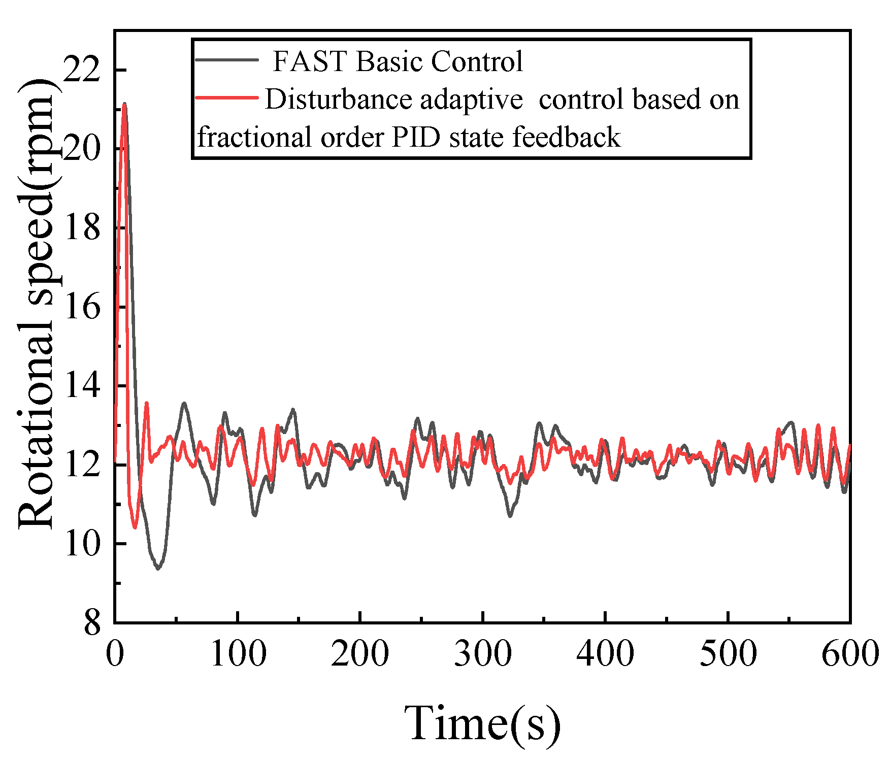
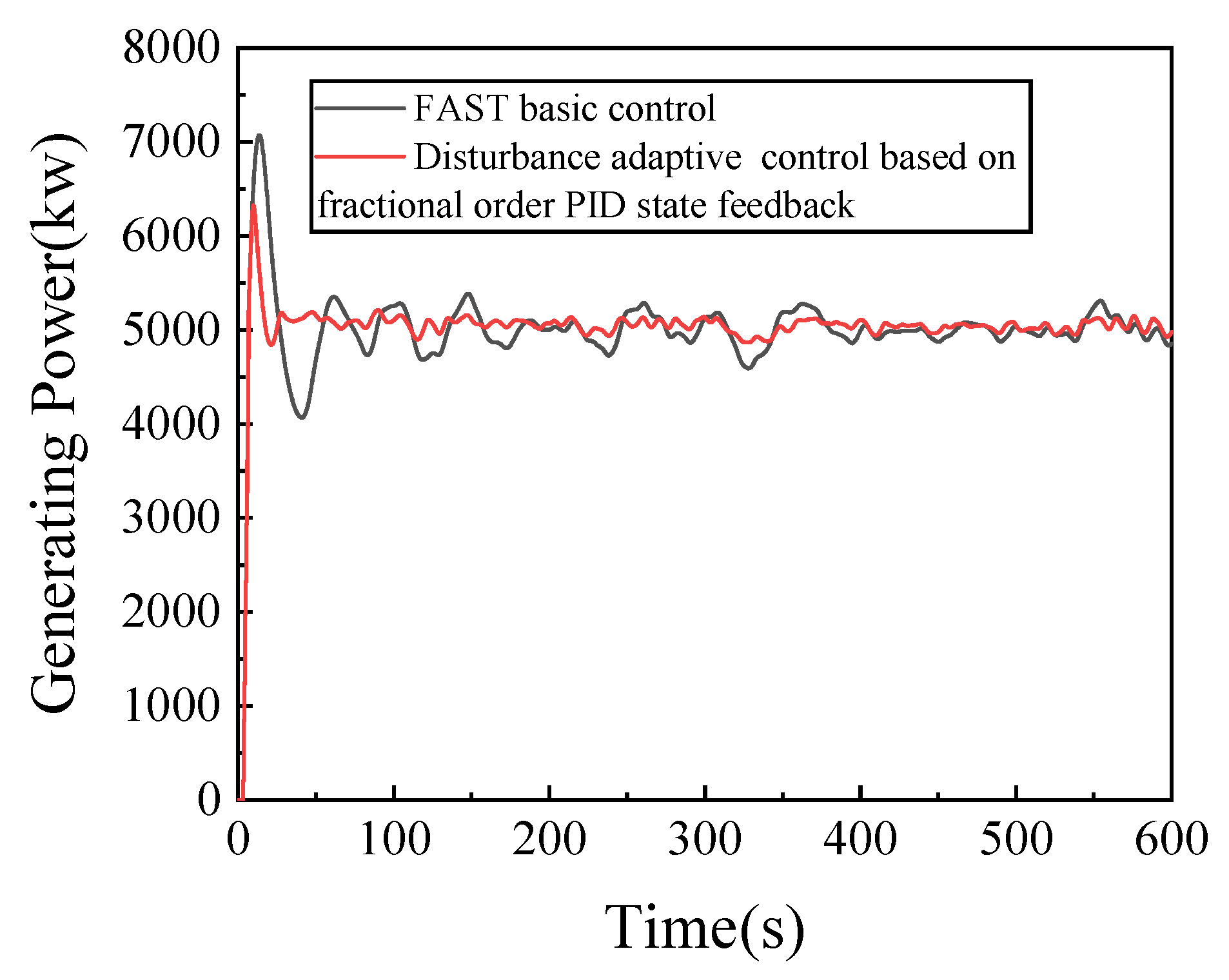
We mainly analyzed the results of wind turbine speed and power generation. Figure 7 and Figure 8 compare the rotational speed and generating power of the floating wind turbine under the two control modes, respectively. Compared with the FAST base control, the disturbance adaptive control with fractional PID state feedback significantly reduces the fluctuation of the rotational speed of the floating wind turbine, although the generating power of the two control methods can be stabilized at about 5 MW. Compared with the FAST base control, under the disturbance adaptive control with fractional PID state feedback, the generating power is more stable and the generating power overshoot is smaller. A detailed comparison of the rotational speed and generating power of the wind turbine is shown in Table 3. Because the generating power and rotational speed of the floating wind turbine are basically stable after 100 s, data from 100 s to 600 s are selected for analysis.
As can be seen from Table 3, under the disturbance adaptive control with fractional PID state feedback and the FAST basic control, the standard deviation of the rotational speed is 0.286 and 0.504, respectively. Compared with the FAST base control, under the disturbance adaptive control with fractional PID state feedback, the standard deviation of the rotational speed is reduced by 43.25%. Under the disturbance adaptive control with fractional PID state feedback and the FAST base control, the standard deviation of the generating power is 60.42 and 152.38, respectively. Compared with the FAST base control, under the disturbance adaptive control with fractional PID state feedback, the standard deviation of the generating power is reduced by 60.35%. This can be summarized as follows: under the disturbance adaptive control with fractional PID state feedback, the fluctuation of rotational speed and generating power is smaller, the generating power is more stable and the control effect is better.

4.2. Stability Analysis of Floating Wind Turbine

Under the combined action of wind and wave loads, the floating wind turbine will produce a six-degree-of-freedom motion, including translation and rotation. Translation includes pitch, sway and heave; rotation includes pitch, roll and yaw.
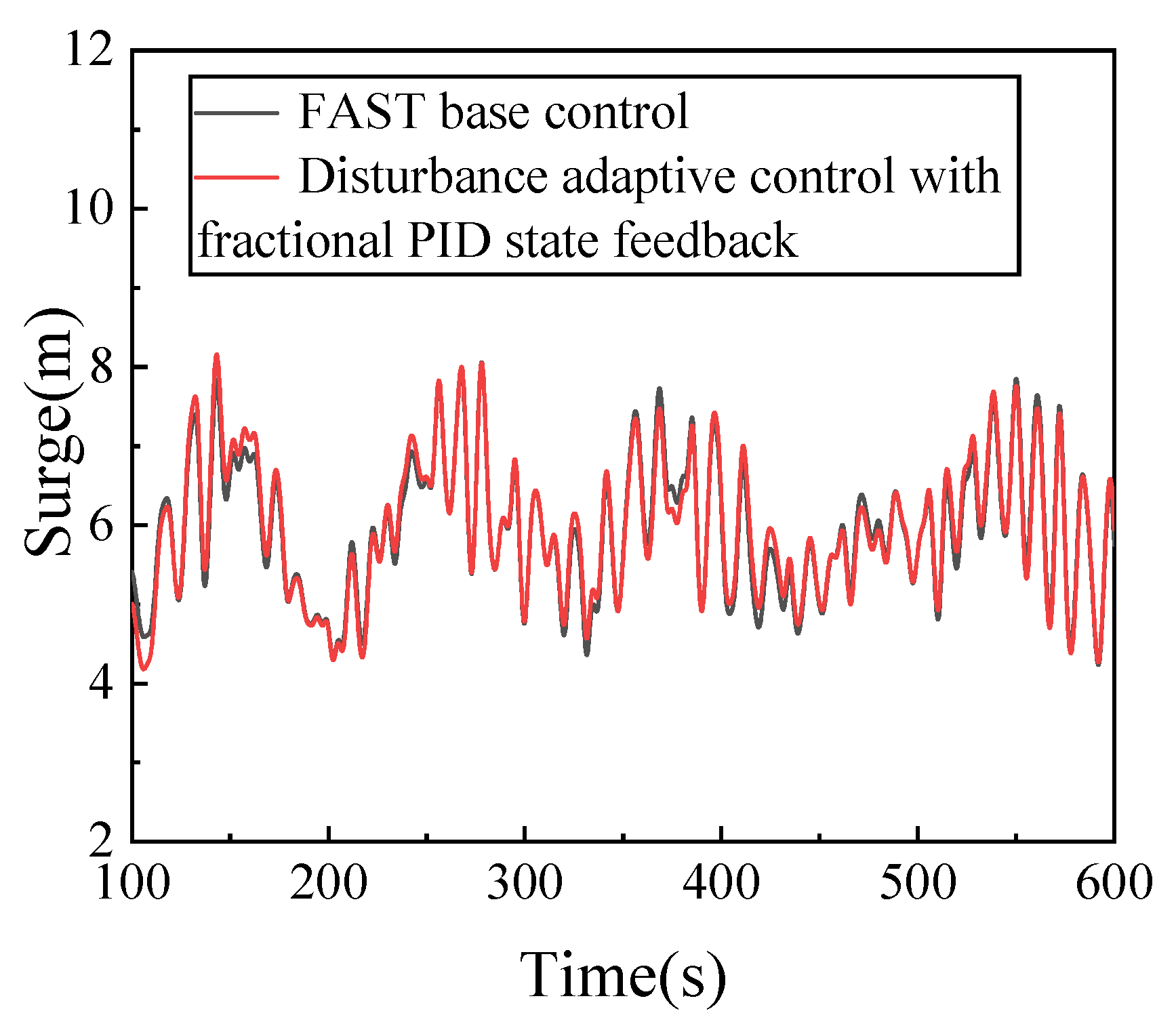
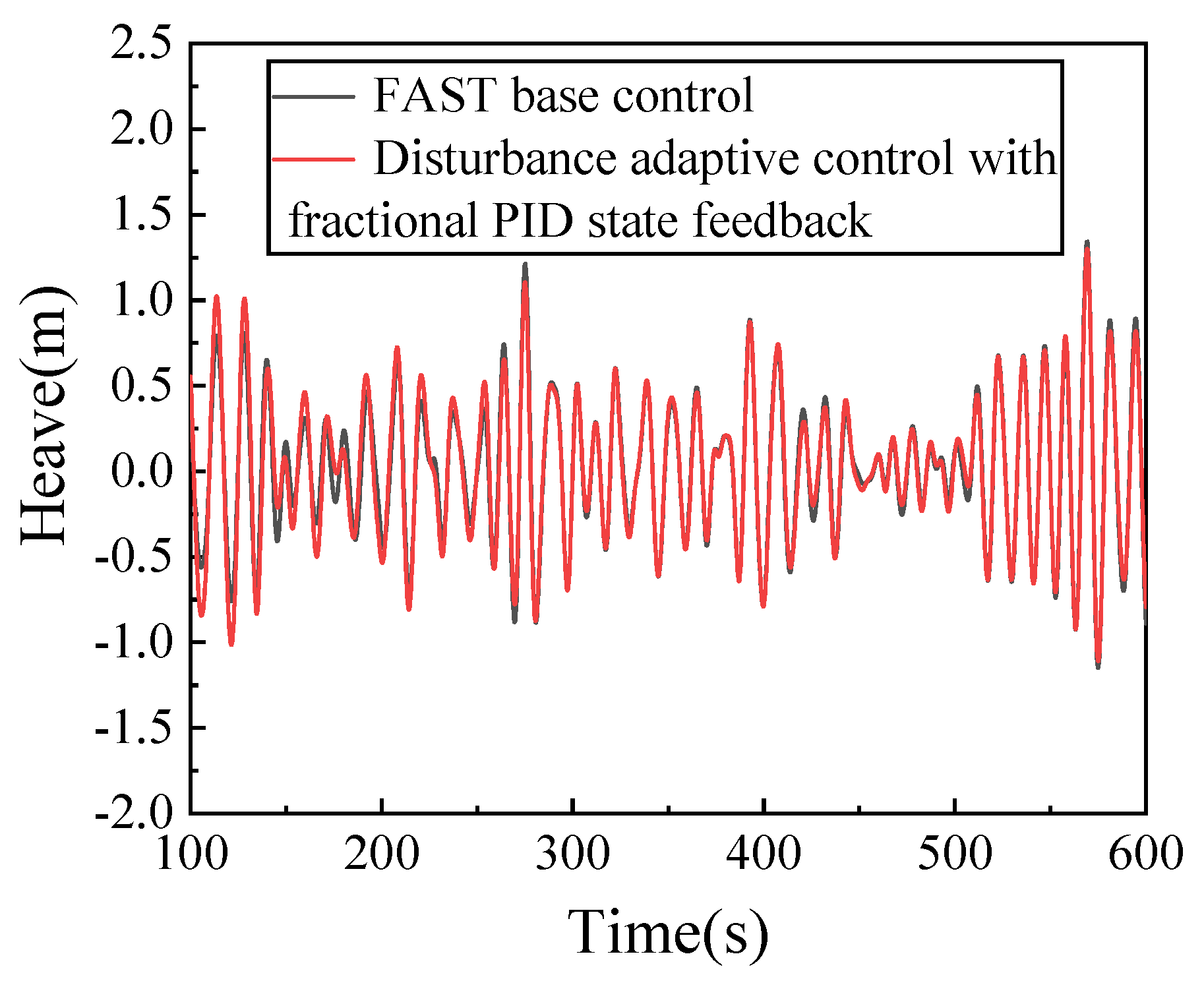
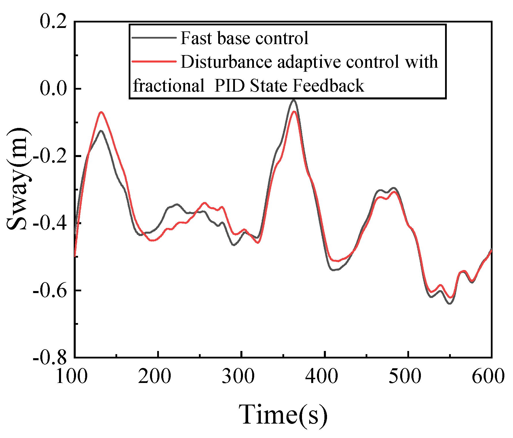
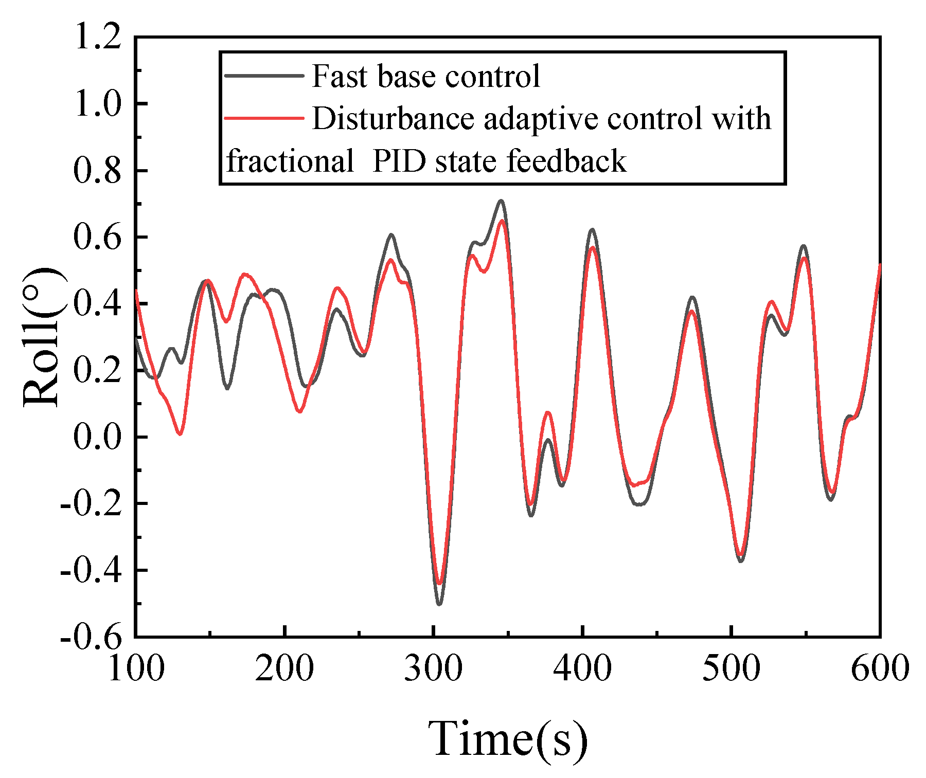
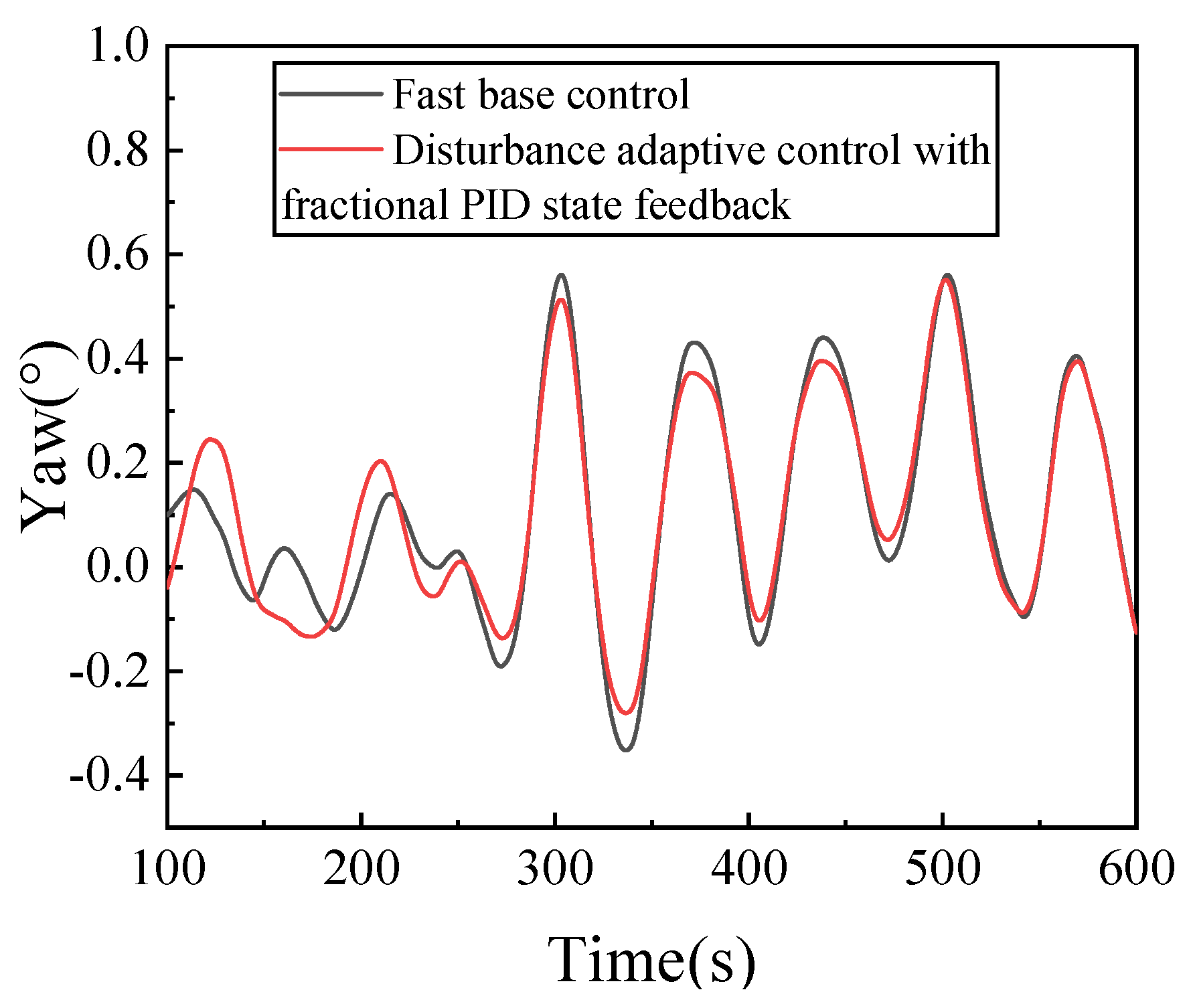
The load acting on the system will change in the process of varying the pitch of the floating wind turbine, which will affect the stability of floating wind turbine. Therefore, it is of great significance to consider the stability of floating wind turbine platform in the design and development of the method for varying the pitch control of the floating wind turbine. Figure 9 and Figure 10 are the comparison of the surge displacement and pitch angle under the two control algorithms. Specific data analysis is shown in Table 4. Under the FAST base control, the standard deviation of the surge displacement and pitch angle are 0.835 and 0.603, respectively. Under the disturbance adaptive control with fractional PID state feedback, the standard deviations of the surge displacement and pitch angle are 0.859 and 0.552, respectively. Compared with the FAST base control, under the disturbance adaptive control with fractional PID state feedback, the surge distance standard deviation is increased by 2.87% and the pitch angle standard deviation is reduced by 8.46%. Figure 11 and Figure 12 are the comparison of the sway displacement and roll angle under the two control algorithms; the specific data analysis is shown in Table 5. Under the FAST base control, the standard deviation of the sway displacement and roll angle is 0.138 and 0.267, respectively. Under the disturbance adaptive control with fractional PID state feedback, the standard deviation of the sway displacement and roll angle are 0.137 and 0.253, respectively. Compared with the FAST base control, under the disturbance adaptive control with fractional PID state feedback, the standard deviation of the sway displacement decreases by 0.721.44% and the standard deviation of roll angle decreases by 5.24%. Figure 13 and Figure 14 show the comparison of the heave displacement and yaw angle of the two control methods, and the specific data analysis is shown in Table 6. Under the FAST base control, the standard deviations of the heave displacement and yaw angle are 0.410 and 0.211, respectively. Under the disturbance adaptive control with fractional PID state feedback, the standard deviations of the heave displacement and yaw angle are 0.426 and 0.20, respectively. Compared with the FAST base control, under the disturbance adaptive control with fractional PID state feedback, the standard deviation of heave control is increased by 3.76% and the standard deviation of roll control is reduced by 5.21%. The results show that under the disturbance adaptive control with fractional PID state feedback, the fluctuation of the floating wind turbine platform in the four degrees of freedom of pitch, roll, sway and yaw decrease, while the fluctuation of surge and heave increase. The control algorithm also plays a certain role in maintaining the stability of the floating wind turbine platform.

5. Conclusions

Taking the 5 MW floating OC4 wind turbine of NREL as the research object, this paper designs a variable pitch control under disturbance adaptive control, based on the fractional order PID state feedback optimized by a genetic algorithm. Having carried out the corresponding simulation experiment, we can draw the following conclusions:
(1)
Compared with the FAST base control, the speed fluctuation of the wind wheel of the floating wind turbine on the sea is lesser; it can be quickly adjusted to changes in wind speed.
(2)
Compared with the FAST base control, the power fluctuation of floating wind turbine is smaller, and the overshoot is smaller and more stable.
(3)
Compared with the FAST base control, the surge and heave fluctuation increase, while the fluctuation of the other four degrees of freedom decreases. The control algorithm also plays a certain role in maintaining the stability of the floating wind turbine platform.

Author Contributions

Methodology, J.Y.; Software, J.Y.; Validation, J.Y.; Formal analysis, J.Y.; Investigation, J.Y.; Resources, J.Y.; Data curation, J.Y.; Writing—original draft, J.Y.; Writing—review & editing, Z.C. and D.L.; Supervision, Z.C. All authors have read and agreed to the published version of the manuscript.

Funding

This research was funded by the national key research and development project “tackling key problems and application demonstration of high-power new onshore wind turbine”, Xinjiang Uygur Autonomous Region Natural Fund Project, Xinjiang Uygur Autonomous Region Key Laboratory construction Project, Major science and technology project of Xinjiang Uygur Autonomous Region, grant number (2021YFB1506902), (2021D01C046), (2021D04011), (2022A1001-3).

Conflicts of Interest

The authors declare no conflict of interest.

References

  1. Mittal, A.; Sreenivas, K.; Taylor, L.K.; Hereth, L.; Hilbert, C.B. Blade-resolved simulations of a model wind turbine: Effect of temporal convergence. Wind Energy 2016, 19, 1761–1783. [Google Scholar] [CrossRef]
  2. Porté-Agel, F.; Bastankhah, M.; Shamsoddin, S. Wind-Turbine and Wind-Farm Flows: A Review. Bound.-Layer Meteorol. 2020, 174, 1–59. [Google Scholar] [CrossRef] [PubMed] [Green Version]
  3. Carraro, M.; De Vanna, F.; Zweiri, F.; Benini, E.; Heidari, A.; Hadavinia, H. CFD modeling of wind turbine blades with eroded leading edge. Fluids 2022, 7, 302. [Google Scholar] [CrossRef]
  4. Niu, Y.-G.; Li, X.-M.; Lin, Z.-W.; Li, M.-Y. Multiple models decentralized coordinated control of doubly fed induction generator. Int. J. Electr. Power Energy Syst. 2015, 64, 921–930. [Google Scholar] [CrossRef]
  5. Ana, S.; Itsaso, M.M.; Tapia, G.; Vechiu, I. Second-order sliding-mode controller design and tuning for grid synchronization and power control of a wind turbine-driven DFIG. In Proceedings of the IET Conference on Renewable Power Generation (RPG 2011), Edinburgh, UK, 6–8 September 2011; IET: London, UK, 2012. [Google Scholar]
  6. Evangelista, C.; Puleston, P.; Valenciaga, F.; Fridman, L.M. Lyapunov-Designed Super-Twisting Sliding Mode Control for Wind Energy Conversion Optimization. IEEE Trans. Ind. Electron. 2013, 60, 538–545. [Google Scholar]
  7. Palejiya, D.; Shaltout, M.; Yan, Z.; Chen, D. Stability of wind turbine switching control. Int. J. Control 2015, 88, 193–203. [Google Scholar] [CrossRef]
  8. Colombo, L.; Corradini, M.L.; Ippoliti, G.; Orlando, G. Pitch angle control of a wind turbine operating above the rated wind speed: A sliding mode control approach. ISA Trans. 2020, 96, 95–102. [Google Scholar] [CrossRef] [PubMed]
  9. Yin, X.; Zhang, W.; Jiang, Z.; Pan, L. Adaptive robust integral sliding mode pitch angle control of an electro-hydraulic servo pitch system for wind turbine. Mech. Syst. Signal Process. 2019, 133, 105704. [Google Scholar] [CrossRef]
  10. Aghaeinezhad, S.M.; Taghizadeh, M.; Mazare, M.; Kazemi, M.G. Individual Pitch Angle Control of a Variable Speed Wind Turbine Using Adaptive Fractional Order Non-Singular Fast Terminal Sliding Mode Control. Int. J. Precis. Eng. Manuf. 2021, 22, 511–522. [Google Scholar] [CrossRef]
  11. Civelek, Z. Optimization of Fuzzy Logic (Takagi-Sugeno) Blade Pitch Angle Controller in Wind Turbines by Genetic Algorithm. Eng. Sci. Technol. Int. J. 2020, 23, 1–9. [Google Scholar] [CrossRef]
  12. Ma, R.; Hu, S.J.; Fu, X.B.; Xu, H.H.; Li, N.H. Torque control and pitch control strategy in VSCF wind turbine above rated wind speed. In Advanced Materials Research II. Part 2; Trans Tech Publications: Stafa-Zurich, Switzerland, 2012; pp. 1715–1720. [Google Scholar]
  13. Aissaoui, A.G.; Tahour, A.; Essounbouli, N.; Nollet, F.; Abid, M.; Chergui, M.I. A Fuzzy-PI control to extract an optimal power from wind turbine. Energy Convers. Manag. 2013, 65, 688–696. [Google Scholar] [CrossRef]
  14. De Corcuera, A.D.; Pujana-Arrese, A.; Ezquerra, J.M.; Segurola, E.; Landaluze, J. H Based Control for Load Mitigation in Wind Turbines. Energies 2012, 5, 938–967. [Google Scholar] [CrossRef] [Green Version]
  15. Namik, H.; Stol, K. Performance analysis of individual blade pitch control of offshore wind turbines on two floating platforms. Mechatronics 2011, 21, 691–703. [Google Scholar] [CrossRef]
  16. Namik, H.; Stol, K. Individual Blade Pitch Control of a Spar-Buoy Floating Wind Turbine. IEEE Trans. Control Syst. Technol. 2014, 22, 214–223. [Google Scholar] [CrossRef]
  17. Lasheen, A.; Elshafei, A.L. Wind-turbine collective-pitch control via a fuzzy predictive algorithm. Renew. Energy 2016, 87, 298–306. [Google Scholar] [CrossRef]
  18. Jafarnejadsani, H.; Pieper, J.; Ehlers, J. Adaptive control of a variable-speed variable-pitch wind turbine using radial-basis function neural network. IEEE Trans. Control Syst. Technol. 2013, 21, 2264–2272. [Google Scholar] [CrossRef]
  19. Lackner, M.A. Controlling Platform Motions and Reducing Blade Loads for Floating Wind Turbines. Wind. Eng. 2009, 33, 541–553. [Google Scholar] [CrossRef]
  20. Jiao, X.; Yang, Q.; Fan, B.; Chen, Q.; Sun, Y.; Wang, L. EWSE and Uncertainty and Disturbance Estimator Based Pitch Angle Control for Wind Turbine Systems Operating in Above Rated Wind Speed Region. J. Dyn. Syst. Meas. Control 2019, 142, 031006. [Google Scholar] [CrossRef]
  21. Shivaji, K.; Ritula, T. Comparative Analysis of Fractional-Order PID Controller for Pitch Angle Control of Wind Turbine System. In Computing in Engineering and Technology; Springer: Singapore, 2019; pp. 647–657. [Google Scholar]
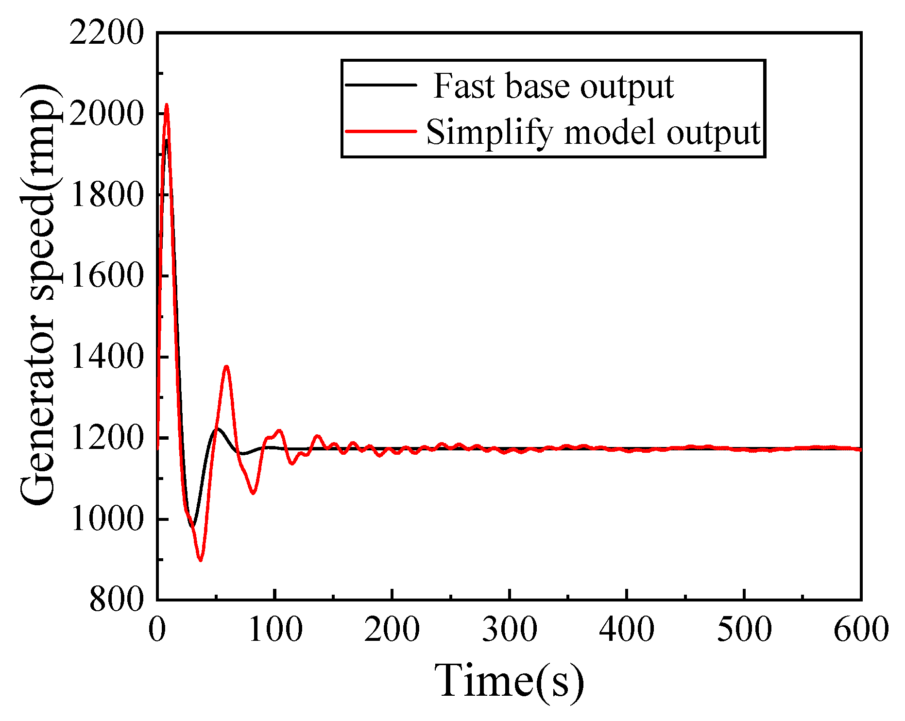
Figure 1. Comparison of generator speed between the base output of FAST and the output of the simplified model.
Energies 16 00821 g001
Figure 2. Comparison of henerator power between the base output of FAST and the output of the simplified model.
Energies 16 00821 g002
Figure 3. Schematic diagram of disturbance adaptive control of PID state feedback.
Energies 16 00821 g003
Figure 4. Genetic algorithm PID optimization flow chart.
Energies 16 00821 g004
Figure 5. Wind speed in KAIMAL spectrum.
Energies 16 00821 g005
Figure 6. PM spectral wave height.
Energies 16 00821 g006
Figure 7. Comparison of rotor speed under two controls.
Energies 16 00821 g007
Figure 8. Comparison of power generation under two controls.
Energies 16 00821 g008
Figure 9. Comparison of surge displacement under two different control algorithms.
Energies 16 00821 g009
Figure 10. Comparison of pitch displacement under two different control algorithms.
Energies 16 00821 g010
Figure 11. Comparison of heave displacement under two different control algorithms.
Energies 16 00821 g011
Figure 12. Comparison of sway angles under two different control algorithms.
Energies 16 00821 g012
Figure 13. Comparison of roll angles under two different control algorithms.
Energies 16 00821 g013
Figure 14. Comparison of yaw angles under two different control algorithms.
Energies 16 00821 g014
Table 1. Parameters of floating wind turbine.
Parameter NameNumerical Value
Number of blades/(m·s−1)3
Cut-in velocity/(m·s−1)3
Rated wind speed/(m·s)11.4
Cut-out wind speed/(m·s−1)25
Rated power/MW5
Height of hub/m126
Diameter of wind turbine/m90
Tower height/m77.6
Running water depth/m200
Tower and top mass/kg599,718
Table 2. Platform parameters of floating wind turbine.
Parameter NameNumerical Value
Diameter of main floating column/m6.5
Diameter of side floating column/m12
Diameter of base floating column/m24
Platform quality/kg13,473,000
Platform pitch moment of inertia/(kg·m2)6.837 × 109
Platform pitch moment of inertia/(kg·m2)1.226 × 1010
Table 3. Control effect parameters under different controllers.
ParameterFast Base ControlAdaptive Disturbance Control Based on Fractional Order PID State Feedback
Rotational speed/(r·min−1)Maximum13.4113.01
Minimum10.6911.55
Standard deviation0.5040.286
Generating Power/(kw)Maximum53845168
Minimum45934868
Standard deviation152.3860.42
Table 4. Comparison of heave displacement and heave angle under two control algorithms.
ParameterFast Base ControlAdaptive Disturbance Control Based on Fractional Order PID State Feedback
Surge/(m)Maximum8.0538.155
Minimum4.2344.181
Standard deviation0.8350.859
Pitch/(°)Maximum4.8555.107
Minimum1.5911.802
Standard deviation0.6030.552
Table 5. Comparison of sway displacement and roll angle under two control algorithms.
ParameterFast Base ControlAdaptive Disturbance Control Based on Fractional Order PID State Feedback
Sway/(m)Maximum −0.034−0.058
Minimum−0.64−0.621
Standard deviation0.1380.137
Roll/(°)Maximum0.7090.664
Minimum−0.502−0.450
Standard deviation0.2670.253
Table 6. Comparison of heave displacement and yaw angle between two control algorithms.
ParameterFast Base ControlAdaptive Disturbance Control Based on Fractional Order PID State Feedback
Heave/(m)Maximum1.3431.3
Minimum−1.149−1.109
Standard deviation0.4100.426
Yaw/(°)Maximum0.5610.547
Minimum−0.352−0.293
Standard deviation0.2110.200
Disclaimer/Publisher’s Note: The statements, opinions and data contained in all publications are solely those of the individual author(s) and contributor(s) and not of MDPI and/or the editor(s). MDPI and/or the editor(s) disclaim responsibility for any injury to people or property resulting from any ideas, methods, instructions or products referred to in the content.