Review

Gas Turbine Combustion Technologies for Hydrogen Blends

by
Donato Cecere
*,
Eugenio Giacomazzi
,
Antonio Di Nardo
and
Giorgio Calchetti
Laboratory of Processes and Systems Engineering for Energy Decarbonisation, ENEA, Via Anguillarese 301, 00124 Rome, Italy
*
Author to whom correspondence should be addressed.
Energies 2023, 16(19), 6829; https://doi.org/10.3390/en16196829
Submission received: 29 August 2023 / Revised: 23 September 2023 / Accepted: 25 September 2023 / Published: 26 September 2023
(This article belongs to the Section A5: Hydrogen Energy)

Abstract

:
The article reviews gas turbine combustion technologies focusing on their current ability to operate with hydrogen enriched natural gas up to 100% H 2 . The aim is to provide a picture of the most promising fuel-flexible and clean combustion technologies, the object of current research and development. The use of hydrogen in the gas turbine power generation sector is initially motivated, highlighting both its decarbonisation and electric grid stability objectives; moreover, the state-of-the-art of hydrogen-blend gas turbines and their 2024 and 2030 targets are reported in terms of some key performance indicators. Then, the changes in combustion characteristics due to the hydrogen enrichment of natural gas blends are briefly described, from their enhanced reactivity to their pollutant emissions. Finally, gas turbine combustion strategies, both already commercially available (mostly based on aerodynamic flame stabilisation, self-ignition, and staging) or still under development (like the micro-mixing and the exhaust gas recirculation concepts), are described.

1. Introduction

In recent years, the detrimental impacts of global climate change have manifested across various facets of our environment. Unless we transition to carbon-free fuels without compromising global energy production and consumption, these adverse changes are poised to persist [1]. A significant portion of emissions, including NO x , CO , CO 2 , results from the combustion of fossil fuels. The shift towards alternative fuels, such as hydrogen, which is devoid of carbon content [2,3,4], represents a crucial and necessary step in addressing this issue.
In 2019, global CO 2 emissions from fossil fuels amounted to 33 Gt, with 41 % coming from the power generation sector, and the rest from the transport and industrial sectors. With the current level of emissions, there are only 15 years left to keep global warming to 1.5 ° C above pre-industrial levels. In 2020, installed power generation with gas turbines was about 1.6 TW globally, and despite the effects of COVID-19 on energy demand, gas accounted for about 22 % of power generation. Gas turbines already perform an important back-up service (both peak and seasonal) to support non-programmable renewables and stabilize (both in voltage and frequency) the electricity grid, with a non-negligible contribution to the flexibility of the electricity system, even in a vision to 2040 (see Figure 1). In this view, the potential annual reduction of CO 2 due to hydrogen operated gas turbines is greater than 450 Mt. In this context, with a highly intermittent and increasingly low operational profile in terms of annual equivalent hours (estimate by 2040 of less than 3000 h per year in Europe), the application of post-combustion capture technologies to gas turbines fueled by natural gas would be unsustainable, both from a technical and economic point of view.
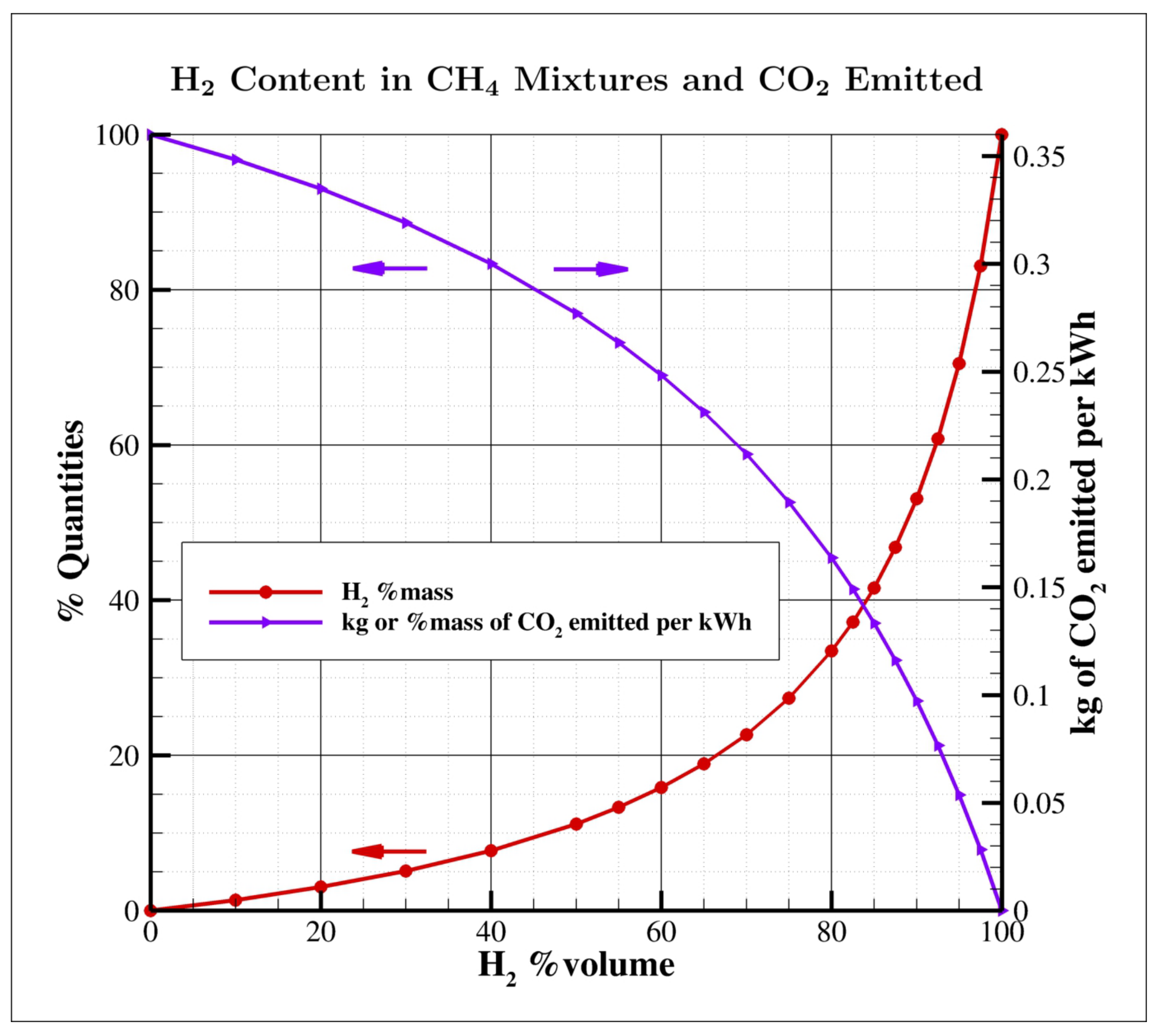
Pre-combustion refers to systems and processes by which a fuel is transformed into another fuel with a lower or no carbon content, capturing CO 2 before the fuel is used. Today, the focus is on hydrogen, which does not emit CO 2 during the combustion process. The possibility of burning hydrogen in a gas turbine avoids the potential “lock-in” of CO 2 emissions for the entire life of the power plant (“blocked emissions” are future carbon dioxide emissions caused by decisions made in the present). In view of an increasingly less massive use of fossil fuels, turbo-gas plants operating with hydrogen/methane mixtures represent an important solution for the decarbonisation of the thermo-electric generation sector and for the sustainability of the energy transition. However, it is important to underline that in order to have a decisive impact on CO 2 reduction, it is necessary to work with mixtures with a high hydrogen content. In Figure 2, the trend of CO 2 reduction as a function of the percentage by volume of H 2 in the CH 4 / H 2 mixture is shown. The trend is non-linear: if you want to achieve a CO 2 reduction of 50 % , it is necessary to have a mixture with about 75 % of H 2 by volume.
Hydrogen is the most abundant element in the universe. However, it does not exist on Earth as an isolated molecule. It is present inside molecules containing other atomic species. To obtain pure hydrogen, it must be separated from the molecules in which it is contained, essentially H 2 O or hydrocarbons (for example, CH 4 ). The current demand for hydrogen is about 70 million tons per year. Approximately 90 % is produced from natural gas or coal, typically by reforming processes [7]. Steam methane reforming (SMR) is one of the methods used to produce hydrogen (“blue hydrogen”) from methane (or natural gas) and water vapor. Since about 9.5 kg of CO 2 are generated for every kg of H 2 produced, the process requires the application of CCUS (carbon capture, utilisation, and storage) techniques to be sustainable. Another method of production of H 2 is the electrolysis of water; this is, today, the clean process par excellence (“green hydrogen”), using renewable sources to power the process [8,9]. Additional emerging technologies encompass a range of biogas production methods, including the gasification [10] and pyrolysis processes [11]. Furthermore, advancements in biomass fermentation utilizing microorganisms have also been explored [12,13]. In addition to these, there are newly developed approaches such as photo-electrochemical water splitting [14] and thermo-chemical processes, including microbial electrolysis [15], aimed at splitting water into H 2 and O 2 with reduced energy requirements compared to conventional electrolysis methods. The considerable quantities of hydrogen required for the decarbonization of the thermo-electric generation sector make the use of “blue hydrogen” inevitable, through the steam reforming process coupled with CO 2 capture techniques. Given the characteristics of current CCS techniques [16,17], it seems sensible to think of a centralized production system (higher volumes and lower capture costs).
When we talk about fuel-flexibility, we currently refer to the ability of a gas turbine to operate, with hydrogenated mixtures, where hydrogen is mixed with other gaseous fuels under several loading conditions, a flame mode, and an acceptable level of emissions [18,19]. Such blends range from hydrogen enriched natural gas (HENG) to ammonia (used as a promising H 2 carrier). The experience gained with the operation of gas turbines powered by syngas with a hydrogen content from 30 to 60 % by volume represents a solid basis for further developments on the combustion of mixtures with higher concentrations.
High hydrogen concentrations can be burned by adopting WLE (Wet Low Emission) technology [20]. NO x emissions can be controlled by decreasing flame temperature by injection of steam or demineralized water with penalties, in regards to combustion efficiency, plant complexity, and, therefore, CAPEX/OPEX costs. The major investments are, therefore, oriented towards lean premixed technologies (Dry Low Emission, DLE) without dilution [21]. Today, it is considered the state of the art among gas turbine technologies using natural gas, as it allows greater efficiencies and the low emissions of pollutants.
Therefore, DLE combustion technologies offer the advantage of operating gas turbines while keeping emissions well below the limits defined by the European Industrial Emission Directives (IED). However, particularly when employed in proximity to lean blowout conditions, these combustion strategies tend to exhibit substantial pressure oscillations. These oscillations result from the interaction between pressure waves associated with the system’s acoustics and heat release. Their amplitudes can surpass 10% of the average pressure within the combustion chamber, whereas acceptable levels are considerably lower. Depending on the combustor’s mechanical design and the oscillation frequency, manufacturers often establish limits that are more than an order of magnitude stricter. These undesired oscillations diminish the stable operational range of gas turbines. They tend to intensify when operating with leaner fuel mixtures, although there are also combustion systems with characteristic frequencies that increase when the mixture is richer. These phenomena are commonly referred to as thermo-acoustic or “operational” combustion instabilities, or more broadly, combustion dynamics. They can pose practical challenges during gas turbine operation, negatively impacting machine reliability and availability. They can lead to issues such as flashback and lean blowout, induce vibrations in mechanical components, and damage the entire system due to cyclic mechanical and thermal stresses on the turbine’s walls and blades. Additionally, there is a risk of releasing broken components into the high-temperature path of the working fluid.
The maximum hydrogen concentration allowed in DLE-type gas turbines varies considerably from one manufacturer to another. Table 1 shows the levels of hydrogen currently accepted by the various classes of gas turbines [22,23], from heavy-duty for industrial use, to aero-derived and micro-turbines ( 20 %   H 2 by vol. refers to lower power). The reason lies in the different combustion temperatures and the different combustion technologies used in the different classes. However, there are no fuel-flexible machines on the market that can handle the entire 0–100% range of hydrogen blended with natural gas. Finding a low NO x combustion strategy to burn high H 2 blends is the goal of gas turbine manufacturers. Currently, NO x emissions are often controlled by gas turbine depowering. It has been also observed that the H 2 addition to natural gas also affects the machine start-up and shutdown procedures. Furthermore, the machine must maintain an adequate degree of “operational flexibility”, i.e., the ability to reliably and safely vary power in a short time to cope with changes in the energy demand.
Table 2 shows the KPIs (Key Performance Indicators) for DLE gas turbines, with reference to the state of the art (SoA) in 2020 and with forecasts for 2024 and 2030. It is noted that, maintaining the same level of NO x , going from 30 % to 100 % H 2 is already a challenge. Moreover, the standardization commonly adopted for NO x at 15 % O 2 in dry conditions (without H 2 O ) cannot be applied to fuels with reactivities and combustion products very different from those of natural gas; a more appropriate normalization is the one suggested in the same table, which uses the mass of NO x in mg per quantity of fuel energy injected in MJ. This new normalization has been suggested not only in the SRIA2021-2027 of the Clean Hydrogen Partnership [22], but also in the Hydrogen Working Group of the European Turbine Network [23]. Regarding the start-up, it should be reminded that this phase is typically carried out with only natural gas or liquid oil.
On the basis of the above discussion and information in the available literature, this paper aims to review and compare the recent advances in GT combustion technologies to identify potential candidate(s) that promise a superior performance for hydrogen blends. Different technology concepts and applications such as DryLowNO x ( DLN ) or Lean Premixed (LPM) air combustion, Aerodynamically Stabilized Combustion and its subcategories (Trapped Vortex Combustor, FlameSheet), Staged Combustion, as well as the performance and operability of some emerging and promising technologies (Micro-Mixing, Exhaust gas Recirculation) with oxidizer/fuel flexibility are covered in this study.

2. Effects of Hydrogen on Combustion

The combustion of hydrogen with air does not generate CO 2 emissions, the main cause of the greenhouse effect; the products of the exothermic reaction with air are water in the form of vapour, negligible fractions of H, OH, and O, and a certain quantity of nitrogen oxides. Furthermore, the combustion of hydrogen does not produce the typical hydrocarbon reaction intermediates, such as CO , and other more complex molecules, some of which are harmful and very reactive [24]. However, the ability of gas turbines to operate with high levels of hydrogen relies on combustion systems adapted to the specific characteristics of this fuel. In fact, hydrogen significantly alters the combustion process compared to natural gas. The main differences are listed below and in Table 3:
  • It has a higher adiabatic flame temperature than methane (see Table 3 where the values of the adiabatic flame temperature ( T ad ) of selected fuels at stoichiometric conditions are reported [19,28]). This temperature also defines the combustion efficiency and the cooling requirememts of the liner; thus, it is important for the GT design [29].
  • The higher adiabatic temperature can lead to an increase in NO x levels.
  • Mixing H 2 with conventional fuels reduces CO emissions since the carbon input decreases at a constant equivalence ratio; the oxidation of CO and CO 2 is increased by the higher concentration of OH and H radicals [30]. Working with the excessive lean mixture, the temperature decreases and CO emissions increase [25].
  • As shown in Table 3, the lower calorific value of hydrogen, on a volumetric basis, is approximately 1 / 3 of that of natural gas; therefore, fuel supply systems capable of providing a higher volumetric flow rate are required.
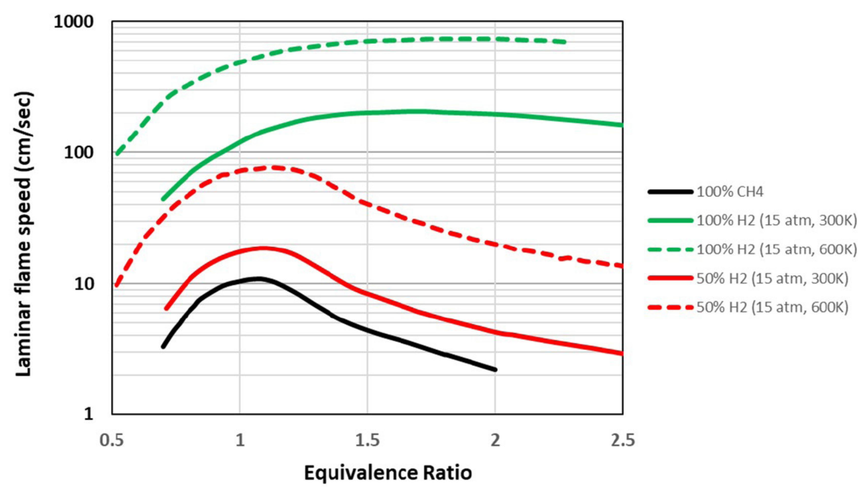
  • Hydrogen has a reactivity about a hundred times greater than natural gas and a higher flame speed of about an order of magnitude [31]. Even mixtures containing hydrogen in various percentages have higher laminar flame speeds than methane alone: a mixture of 50 % hydrogen has twice the flame speed compared to 100 % methane [25,32,33]. Figure 3 shows the trend of the laminar flame speed as a function of the equivalence ratio.
  • The ignition delay time decreases with the H 2 addition [34,35]. Designing the premixer to preclude autoignition requires knowledge of the fuel mixture ignition delay time and the local conditions relative to a premixing time scale.
  • The higher flame speed (due to the increased production of OH, H, O radicals and the higher molecular diffusivity of H 2 [36]) increases the risk of dynamic instabilities (i.e., flashbacks where turbulent flame speed exceeds the flow velocity, typically in the flow boundary layer, allowing flame propagation inside the mixer, with obvious problems of material resistance and safety). Furthermore, H 2 enrichment increases the critical strain rate and minimizes the quenching possibilities of the flame [37,38].
  • High H 2 content increases the risk of thermo-acoustic instabilities characterized by large amplitude pressure oscillations that are driven by unsteadiness in the phase heat release, which strongly alters the combustion process. Shorter convective time scales of the methane–hydrogen mixture and faster reaction rates affect the phase relationship between the fluctuating pressure and unsteady heat release [39,40,41,42,43,44] Although, for many years, both the research and industrial worlds have investigated combustion instabilities [45,46,47], the problem is still not completely solved. The strategies employed to avoid or reduce its effects are substantially based on empirical methods. In addition, lean H 2 flames are highly thermo-diffusively unstable, which means that wrinkles in the flame will tend to become more pronounced, thus justifying the higher turbulent flame speed of lean H 2 flames compared to other lean mixtures [48].
  • The combustion of hydrogen produces flames that are not very bright; therefore, most of the energy is transmitted by convection, by the sensible heat in the exhausted gas [49].

3. Low NO x   H 2 -Ready Combustion Technologies

NO x are emissions basically comprised of nitrogen oxide ( NO ) with smaller amounts of nitrogen dioxide ( NO 2 ) and nitrous oxide ( N 2 O ). In terms of global warming, their effect (particularly that of NO 2 ) is about 136 times more powerful than CO 2 , even though their lifetime is only a few weeks in the atmosphere [51]. In the stratosphere, they lead to the formation of ozone ( O 3 ) which is very dangerous and at the same time, they reduce the amount of ozone itself in the troposphere, where it is needed to protect the earth from ultraviolet rays. Furthermore, NO x are harmful to humans, as they damage the respiratory system. Consequently, it is essential to reduce their emissions. NO x are formed through five pathways. The formation depends on numerous factors, such as, the temperature, the residence time, and the equivalence ratio. Each path first involves the formation of NO which reacts with oxygen to form NO 2 . The main NO formation paths are thermal, prompt, NNH , N 2 O , and Fuel NO:
(1)
Thermal NO or Zeldovich mechanism [52]. The reactions of this mechanism require a high activation energy, thus high temperatures, to activate them [53,54].
R1: N 2 + O = NO + N
R2: N + O 2 = NO + O
R3: N + OH = NO + H
The rate of NO formation strongly depends on temperature, pressure, and residence time; decreasing any of these three reduces NO, but the exponential dependence on temperature makes the reduction of the combustion temperature the key strategy for low NO x combustion. Fortunately, thermal NO x formation rates are relatively slow, and therefore, equilibrium concentrations are never reached in the combustion devices. It is also dependent on the square root of the pressure [55]. NO x emissions can be reduced by lowering the flame temperature or by reducing the time that the mixture spends in the combustor. With H 2 bland fuel, it is possible to simultaneously reduce the length of the combustor and working with a leaner mixture due to the higher flame speed and to the lower flammability limit compared to natural gas.
(2)
Prompt NO. The mechanism initiated by attack of CH n -radicals on N 2 is termed prompt NO [56,57,58].
R4: CH + N 2 = NCN + H
R5: NCN + O = NO + CN
R6: CN + O 2 = NO + CO
R7: NCO + O = NO + CO
(3)
NNH pathway [59,60]. This mechanism is important at higher temperature conditions in the fuel-rich side of the flame zone as well as in the reaction zone.
R8: N 2 + H ( + M ) = NNH ( + M )
R9: NNH + O = NO + NH
R10: NNH + OH = NO + NH 2
(4)
N 2 O pathway [61]. The N 2 O pathway seems to be significant at high pressures and moderate temperatures in the fuel-lean flame conditions.
R11: N 2 + O ( + M ) = N 2 O ( + M )
R12: N 2 O + H = NO + NH
R13: N 2 O + O = 2 NO
(5)
Fuel NO [51,56]. When nitrogen is chemically bound to fuel (e.g., NH 3 ), it converts almost completely to NO x in the exhaust gases. From the thermal decomposition of fuel-bound compounds in the reaction zone, radicals such as HCN , NH 3 , N , CN and NH can be formed and converted to NO x [62]. While most gaseous fuels, such as natural gas, do not contain fuel-bound nitrogen, nitrogen is frequently present in liquid and solid fuels. Unprocessed fuel oil, for instance, can contain more than 1000 parts per million (ppm) of bound nitrogen, resulting in over 40 ppm of nitrogen oxides ( NO x ) in the exhaust gases solely due to this mechanism. Additionally, the sulfur content in liquid fuels can contribute to acid rain and harm the catalysts used to control emissions in automobiles. Fortunately, refining processes designed to remove sulfur also eliminate nitrogen from the fuel. Ultra-low sulfur diesel (ULSD), as defined by ASTM D975 and containing less than 15 ppm of sulfur, typically contains less than 10 ppm of fuel-bound nitrogen, resulting in less than 1 ppm of NO x being added to the exhaust. Low sulfur diesel (LSD) contains less than 500 ppm of sulfur and can introduce a few ppm of NO x into the exhaust. In contrast, high sulfur diesel, with sulfur levels of up to 5000 ppm (0.5%), also contains a significant amount of fuel-bound nitrogen, which can contribute an additional 50 ppm of NO x . Such levels are generally considered unacceptable in regions where NO x emissions are regulated.
The NO x reduction strategies can be divided into primary and secondary measures. The primary measures involve the modification of the combustion process, such as peak temperatures or residence times reduction; the secondary ones instead consist of the treatment of the exhausted gases downstream of the combustion chamber, with the aim of converting the NO x into less harmful gases, such as H 2 O and N 2 . In most cases, the primary measures require geometric modifications and are, therefore, more suitable for new combustor designs but more difficult to apply in combustors already in operation. The reduction of the reaction temperature can be obtained using lean mixtures or by the injection of water and/or steam inside the combustion chamber. NO x reduction technologies that do not consider water or steam injection are called “Dry Low NO x ” (DLN) or “Dry Low Emission” (DLE) technologies. Since the injection of water or steam into the combustion chamber leads to a reduction of the combustion efficiency and of the entire thermodynamic cycle of the plant, the attention is mainly directed to DLE technologies.
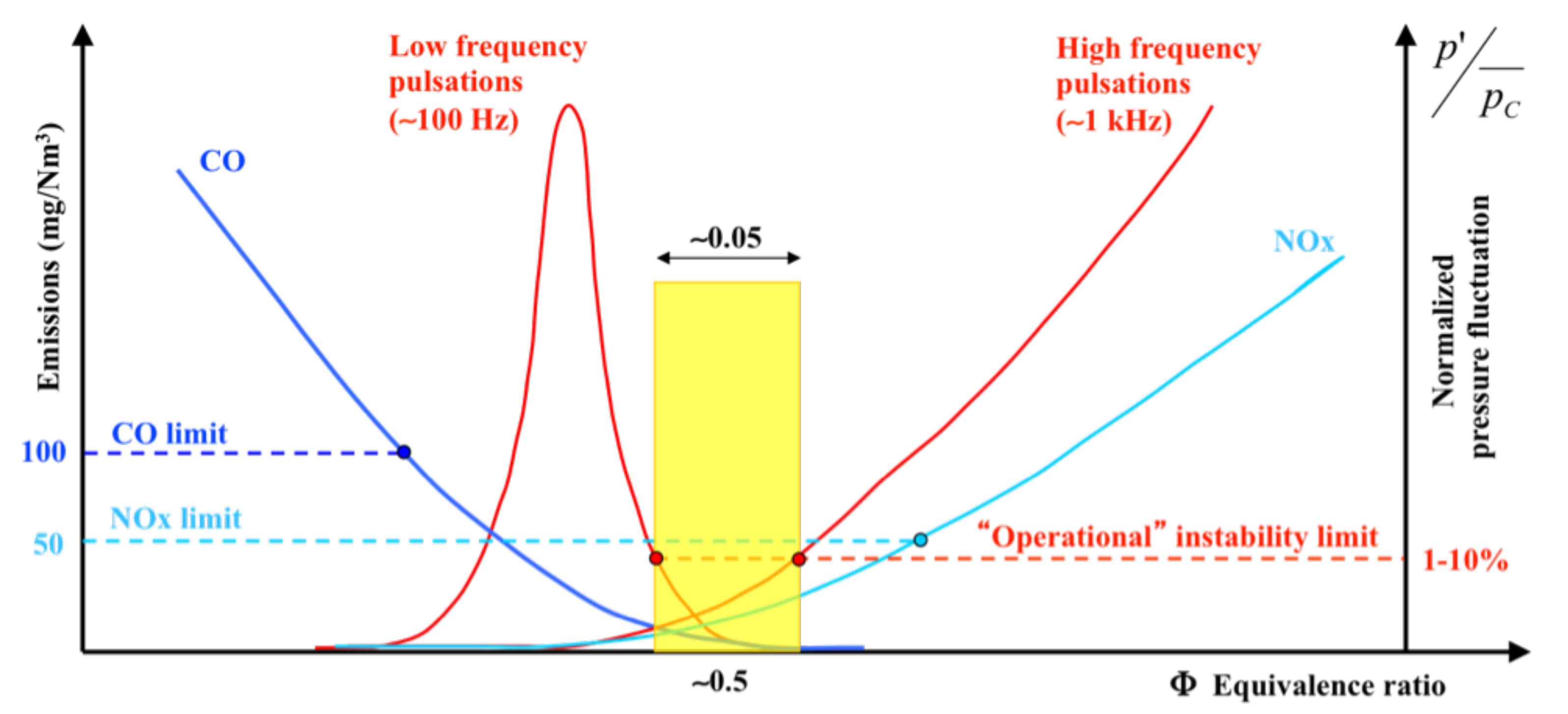
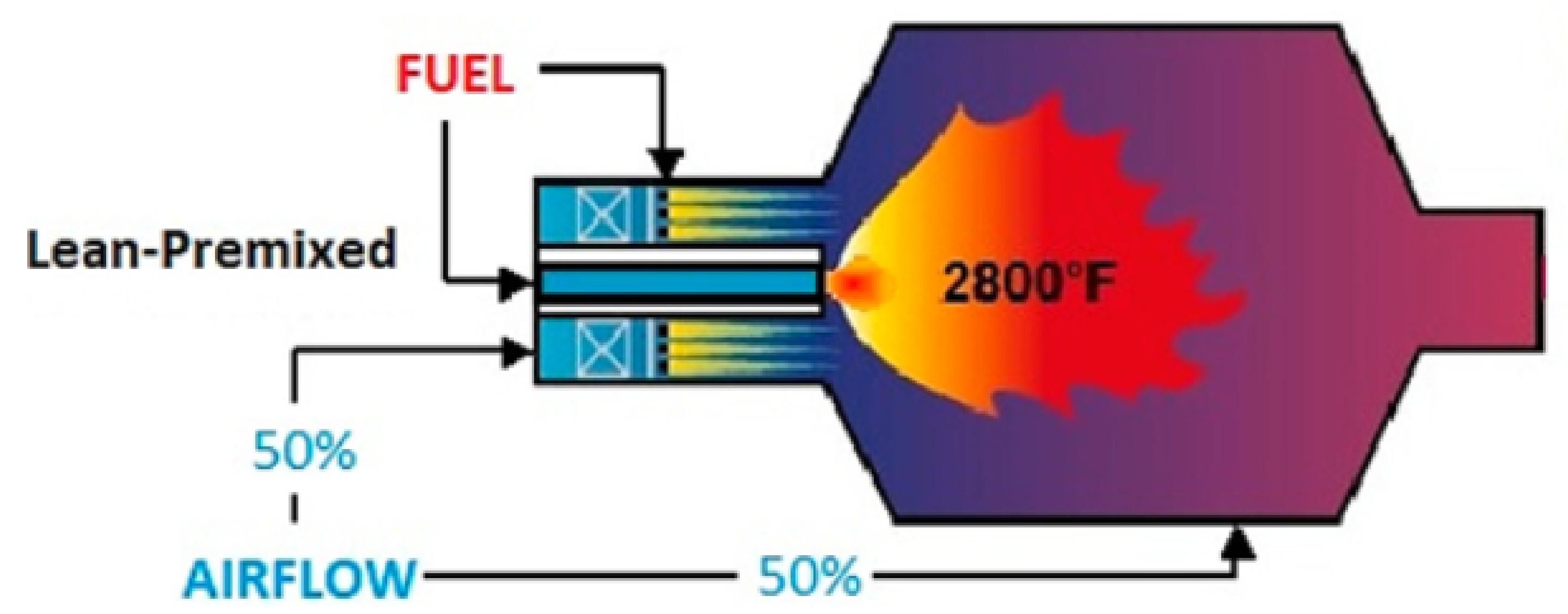
The DLN or DLE combustion technologies are all lean premixed or partially premixed since this allows for greater temperature and NO x control. A good mixing is required for the abatement process to be effective. However, residence times and sufficient volumes may be necessary, such that it is difficult to avoid self-ignition or flash-back. Figure 4 shows the operating principle of Lean Premixed Combustion: in the mixing area, the fuel and the hot air coming from the compressor mix but do not have to react until they enter the combustion chamber. As already noted, these combustion strategies tend to show dangerous thermo-acoustic instabilities (especially close to lean quench conditions) [63,64], which can reduce the machine availability for unplanned maintenance or even damage it seriously. Figure 5 qualitatively highlights the ability of lean premixed technologies to control pollutant emissions, thanks to the adoption of a low equivalence ratio, and at the same time, it shows the narrow operating range due to the onset of thermo-acoustic instabilities.
The following sections report the combustion technologies implemented to reduce NOx formation, with a particular emphasis on those technologies aimed at increasing the fuel flexibility in gas turbines, i.e., increasing the range of H 2 content in natural gas-hydrogen mixtures [67]. These systems can be classified into four groups, depending on the strategy adopted for stabilizing combustion:
  • combustion aerodynamically stabilized by propagation;
  • combustion stabilized by self-ignition;
  • staged combustion, stabilized with different methodologies (by propagation and/or self-ignition); and
  • micro-mixing combustion, with many small premixed, partially premixed or diffusive flames.
These strategies can be hybridized with the recirculation of burnt gases at the compressor intake, a technology known as Exhaust Gas Recirculation (EGR).

3.1. Aerodynamically Stabilized Combustion

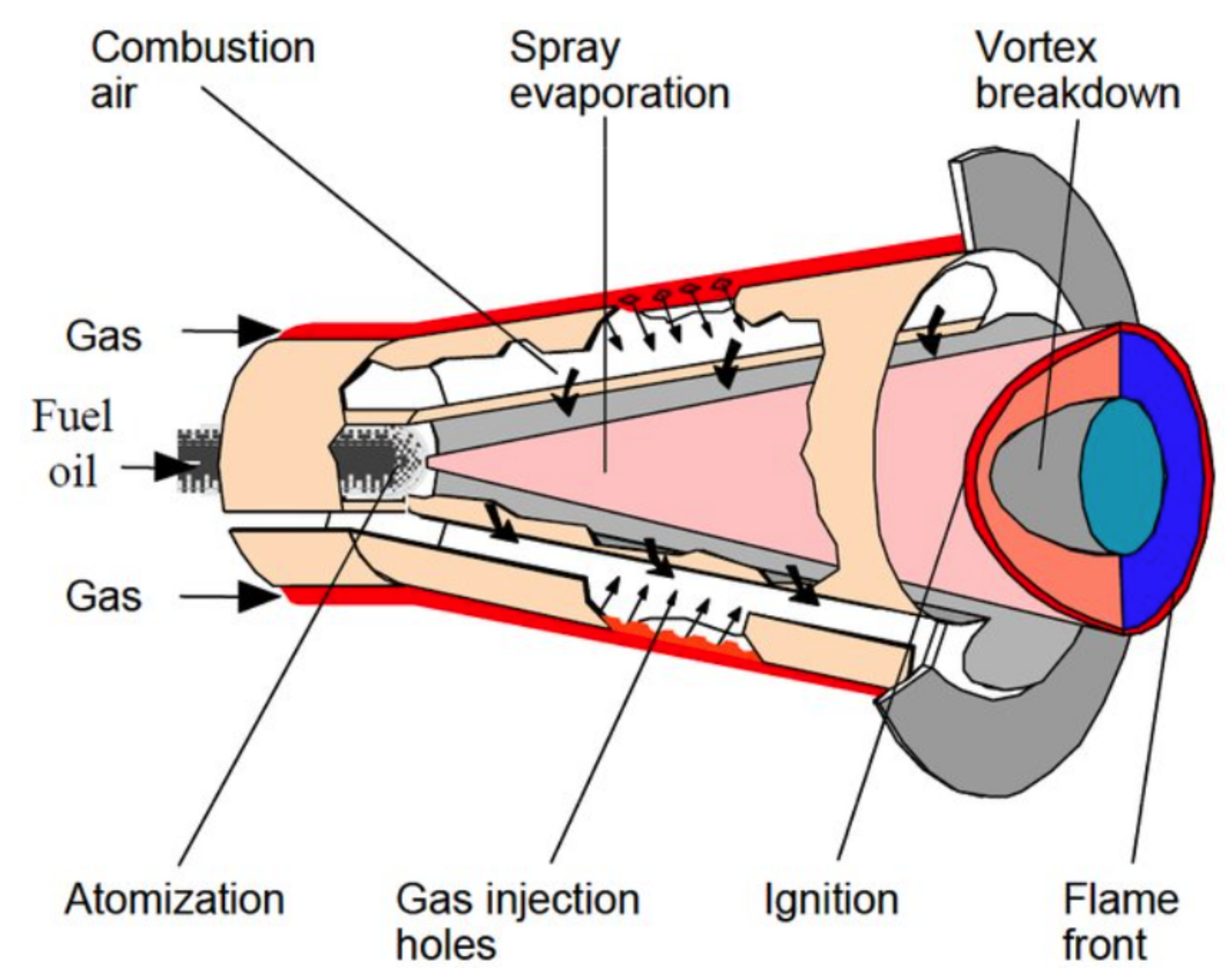
These combustors are based on the generation of suitable recirculation zones which stabilize the combustion, generally by propagation [68]. An aerodynamic stabilization strategy of widely-used premixed flames consists of the use of swirled jets. These burners generate a flow with a strong rotational component by means of vanes or tangential jets that stabilizes the flames in several ways, improving combustion quality and shortening the reaction zone. The swirled flow generates a central recirculation zone: in the expansion phase, the jet is characterized by a radial pressure gradient with a low-pressure region on the axis; when the resulting adverse pressure gradient along the axis of the jet is high enough, it induces an axial reverse flow and creates a vortex breakdown region. The essential mechanism of flame stabilization at a high swirl number (SN > 0.6) is due to the recirculation of the hot combustion products in the recirculation zone, where they mix with the fresh reactants, providing a continuous source of ignition, and also due to the increase in the residence time of the reactants in the reaction zone. Figure 6 shows an advanced burner of the DLN type with the vortex breakdown stabilization mechanism: the ALSTOM/ANSALDO EV burner. A more efficient version of EV is developed by means of sequential combustion [69].
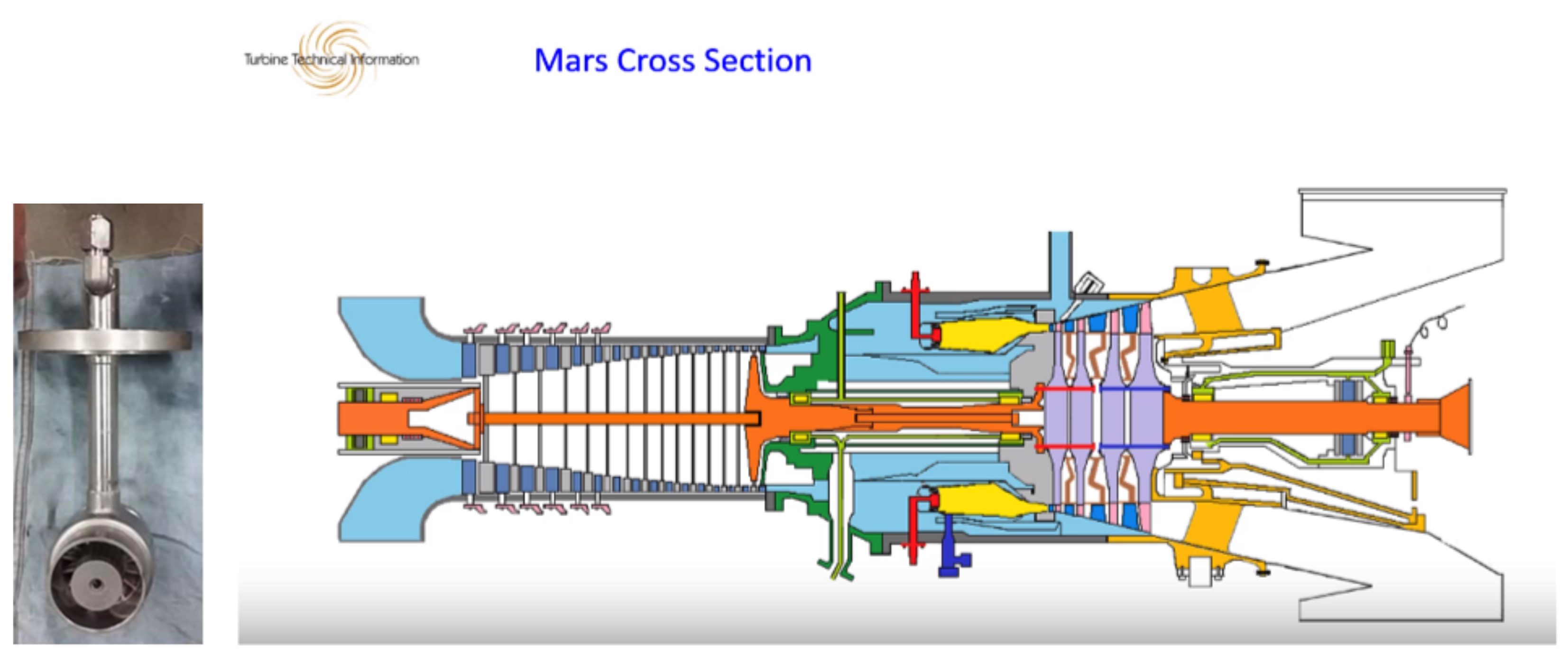
Another aerodynamic stabilization technique of premixed flames is that of SOLAR Turbines, which in 1992, developed the SoLoNOx™ (Solar Low NO x ) combustion technology, which is used to control NO x and CO emissions. The concept exploits a premixed system (lean premixed combustion) with a pilot [71]. It is based on the fact that CO is mainly formed below 1400 ° C [72] while NO x is basically formed at a temperature above 1500 ° C [51]. By keeping the temperature within this range, the emission levels of the two pollutants remain within acceptable levels. In 2021, the technology operated up to 20 % hydrogen by volume. Figure 7 shows the cross-section of a SOLAR Turbines machine with the SoLoNOx technology. The Mars SoLoNOx annular combustion system [73] includes fourteen injectors. Each injector consists of a diffusive pilot and a premixed main part. The pilot circuit is used for startup and in low-power operating mode. Pre-mixing of fuel and air is achieved in an annular duct, where the fuel is injected into the swirling air flow at multiple points. Since the combustor is based on premixed technology, there is no dilution zone, as the radial temperature profile is sufficiently uniform. Preliminary tests have highlighted a limited low-emission operating range of the premixed burner. The system was then equipped with an air bleeding system to maintain the optimal air/fuel ratio value for each load condition. The bleeding system is controlled by a single butterfly valve, located on the side of the engine.
A strategy, in which a macro-recirculation used for combustion stabilization is produced by geometric effect, is instead the Trapped Vortex Combustor (TVC) [75]. Combustion stability is obtained by geometric cavities, where recirculation zones of hot products are generated by the direct injection of fuel and air, and which act as a continuous source of ignition for the incoming fuel-air main flow. The Trapped Vortex Combustor is an efficient and compact combustor, with a stable performance over a wide range of fuel flow rates and with low pressure losses. Different strategies can be implemented in order to reduce NO x : the rapid mixing of fuel and oxidant, staged combustion with a lean or premixed mixture, high inlet velocities with reduced residence time, and in the rich-burn quick-quench lean-burn (RQL) mode. Figure 8 reports the evolution of the TVC during years [75].
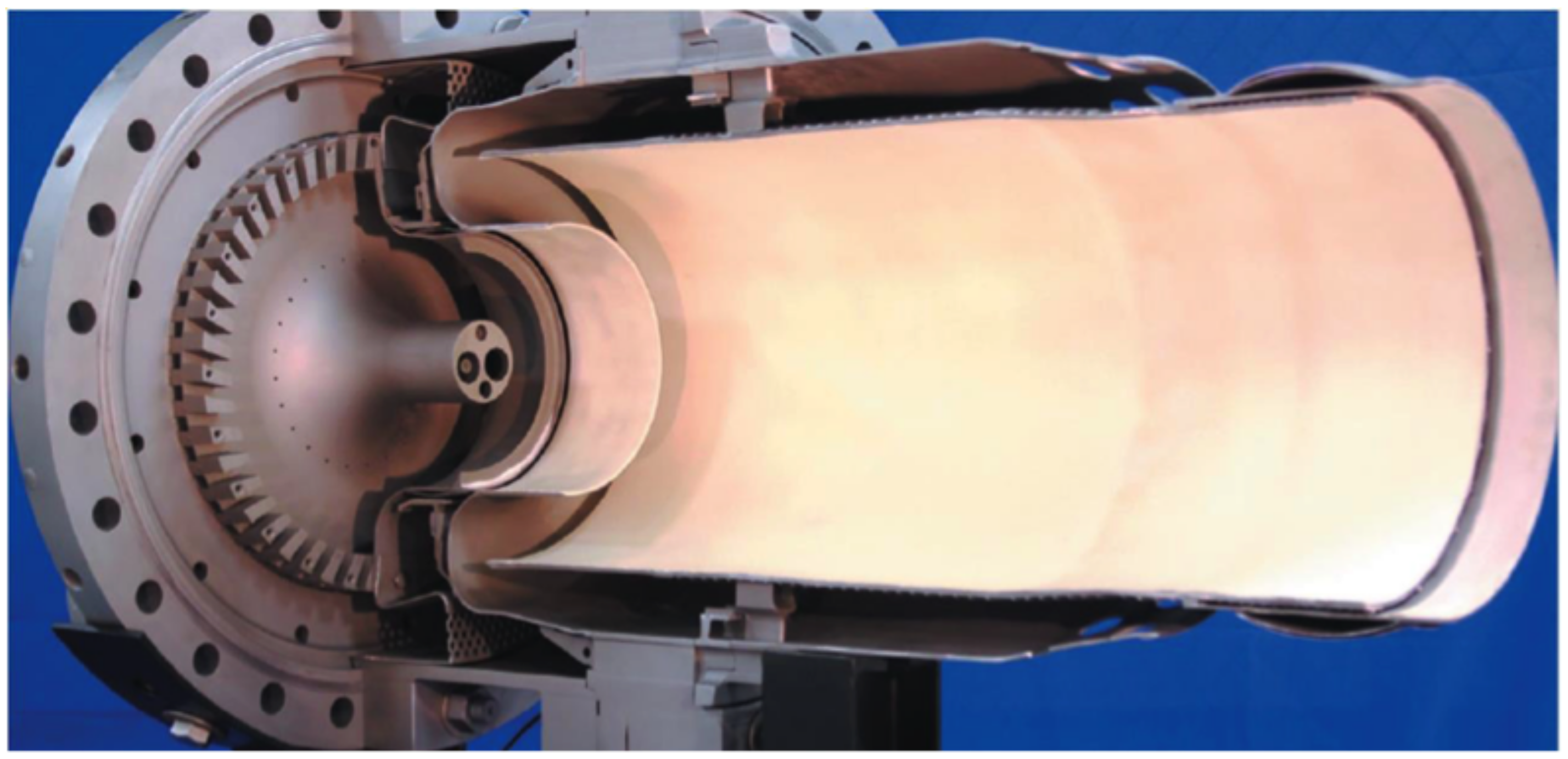
A recent premixed combustion technology, which belongs to the aerodynamically stabilized burner category, is the FlameSheet TM by THOMASSEN Energy [76,77]. It has considerable similarities with the TVC, but in this case, the vortex which guarantees flame anchoring and stability is “trapped” aerodynamically and not geometrically. The combustor has two distinct parts (Figure 9 and Figure 10): a pilot and a main combustor (main stage). The pilot is located along the axis of the combustor, while the main stage surrounds it. The pilot and the main stage are two essentially independent burners, being able to operate independently, thus allowing considerable operating flexibility. The pilot air flows through an external circuit until the burner head where it passes through a radial swirl and is then mixed with fuel before entering the combustion chamber. A stabilized flame is created by the swirled flow downstream of a bluff-body, placed in the center of the combustor. The main air flows instead through an internal circuit where fuel is injected to form the mixture, and then is turned 180 ° and flows into the main stage combustor. The strong recirculation zone, which constitutes the aerodynamically trapped vortex, stabilizes the flame (similar mechanism to a backward facing step, but more effective), while the considerable aerodynamic stretching prevents the pre-ignition of the reactants. Figure 11 shows the results from the test rig at General Electric Fclass conditions. It is confirmed that up to 65 % of blended hydrogen by volume with natural gas can be consumed safely without the risk of flashback and with a NO x emission performance below 7 ppm. The FlameSheet TM technology has been demonstrated up to 80 % of hydrogen by volume on a single full-scale, full power “can” in a test facility, with low NO x emissions and without the need for a diluent such as nitrogen and without a performance impact [78]. The combustor offers superior turn-down. If, at full load, both stages are used, at low loads only the main stage operates, in a stable and low CO emissions condition. Moreover, thanks to the efficient mixing and exit velocities, it can tolerate MWI (Modified Wobbe Index) variation up to 30 % , without affecting emissions [29,79]. This technology is suitable for retrofitting gas turbines, since it has been designed with a view to replace the combustors of various gas turbines already existing on the market (GE (6F, 7E, 7F, 9E, 9F), Siemens/Mitsubishi (501F, 501G, 701F, 701G), and Siemens (501B/D)).

3.2. Stabilized Combustion for Self-Ignition

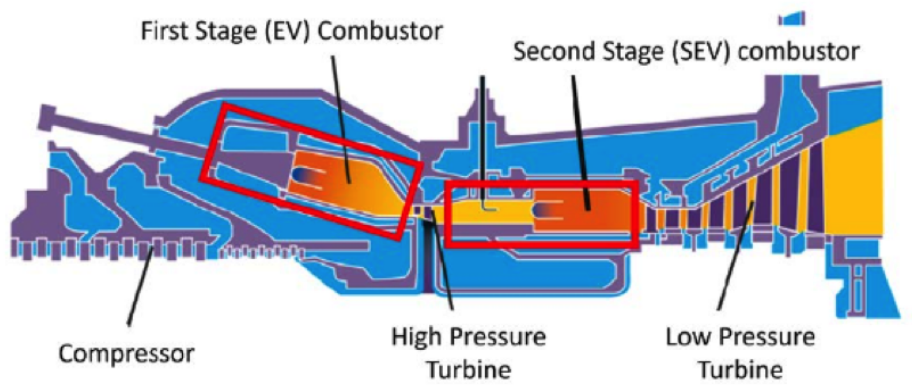
Self-ignition combustion occurs when the reactants are injected into a region with a higher temperature than the ignition temperature. An example can be found in the second combustor of the constant pressure sequential combustion developed by ALSTOM/ANSALDO, in which the fuel is injected into the exhaust gas stream coming from the first combustor (of the EV type, as in Figure 6), to which fresh air has been added.
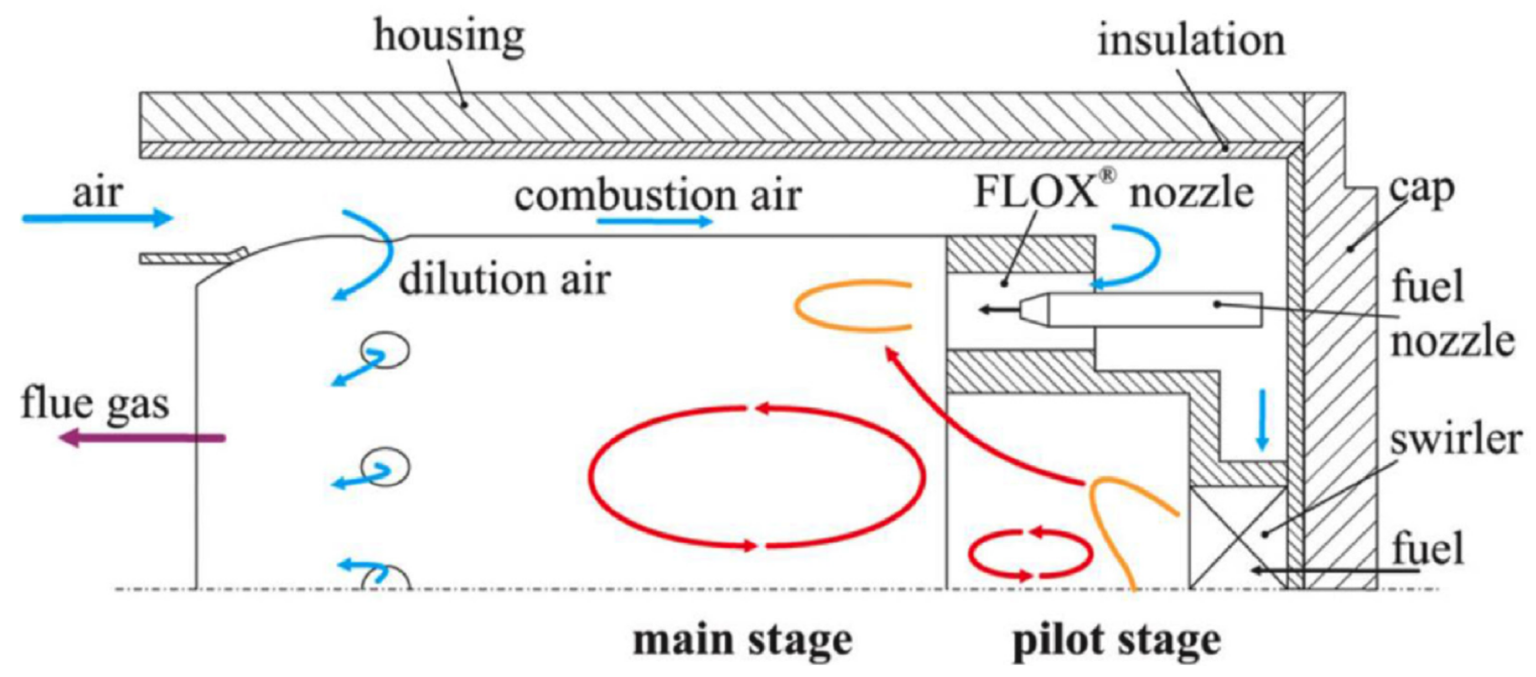
Flameless Oxidation ( FLOX TM ) is another example of self-ignition combustion technology. In FLOX or MILD combustion, flue gas ( N 2 , CO 2 , H 2 O ) is recirculated within the combustor back to the flame front to reduce the O 2 concentration in the oxidant and to heat the reactants above the auto-ignition temperature [81,82,83]. This strategy generates uniform temperature distribution, with reduced peaks, and a consequent reduction of NO x formation [81]; moreover, the flame is not visible (low OH concentrations). Basically, this approach is based on the creation of a volumetric reaction zone, where the fuel and oxidizer, separated or partially premixed, are injected into the combustion chamber at high speed. The momentum of the jets and a suitable combustion chamber geometry promote the internal recirculation of the hot flue gases which preheat and dilute the reactants, stabilizing the combustion. Although the residence time increases in this way, NO x production is limited due to the low temperatures. Figure 12 schematically shows the operating principle of a flameless combustor.
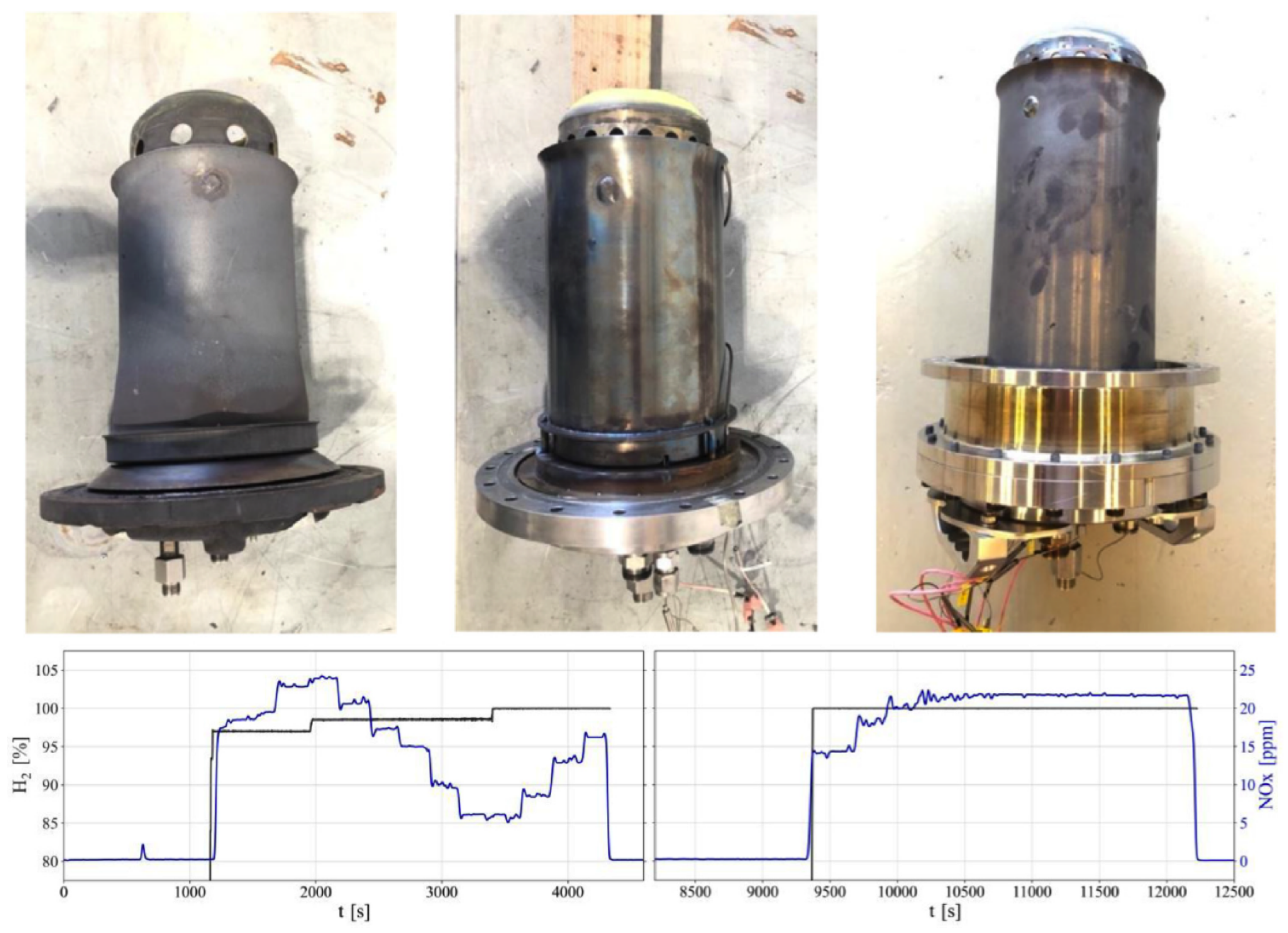
Its principle was originally discovered by Wunning for atmospheric industrial furnaces used in the steel industry [84]. The flameless combustion technology is commercially available for reheating furnaces in the steel sector, with devices already able to operate with natural gas and hydrogen mixtures up to 100 % H 2 . The uniform distribution of temperatures offers the potential for attaining elevated combustion chamber temperatures, thereby enhancing overall efficiency. In the gas turbine sector, there are only some numerical and experimental examples [86,87,88]. Banihabib et al. [85,89] conducted modifications on a 100 KW AE-T100 PH micro-gas turbine swirl-type combustor, originally designed for natural gas usage. They implemented the FLOX® stabilization principle (specifically, the F400s.3 combustion system developed by DLR; see top in Figure 13) to enable the use of hydrogen-enriched fuel and eventually, pure hydrogen. The hydrogen content in the fuel was volume-based and ranged from 40% to 100%. Their findings demonstrated the sustained operation of the micro-gas turbine with nitrogen oxide ( NO x ) emissions consistently below the regulated limits. For pure hydrogen at full-load operation, the highest recorded NO x emissions were 22 ppm, which corresponds to 62 ppm when corrected based on a reference of 15% oxygen in the exhaust gas (see the emission plot in Figure 13).

3.3. Staged Combustion

In staged combustion, the reaction zone can be divided in two parts: a zone with a high equivalence ratio (first stage) and a zone where the equivalence ratio is lower (second stage). As an example, we can report the RQL concept (Rich-Burn, Quench (or Quick-mix), Lean-Burn) introduced in 1980 by Mosier and Pierce. It is essentially a staging technique still used successfully today [90]. In Figure 14, we can see a scheme of an RQL combustor.
In the first stage, the reacting mixture is characterized by an average equivalence ratio of about 1.4 . In this area, the low temperatures and low oxygen concentration do not allow the formation of NO x . In the second stage, dilution air is added, thus producing a lean mixture zone. In this area, the formation of nitrogen oxides is limited by the temperature reduction caused by the addition of dilution air. The main problem is the transition between the rich and the lean zone, which necessarily implies the passage through stoichiometric conditions, causing a high production of thermal NO x due to high temperatures. To limit the formation of NO x in this phase, the mixing with the secondary air must be very rapid and uniform to reduce the residence times at high temperatures and, consequently, the formation of thermal NO x .
This combustion strategy is also of potential interest for ammonia combustion, currently considered one of the best H 2 -carriers. The direct combustion of ammonia has significant problems in terms of reactivity and NO x production. Considering that ammonia-rich combustion generates low NO x (particularly at high pressure) [92], and that the kinetics of H 2 / NH 3 mixtures alter the reaction pathways related to NO x formation [93], staged combustion could be the key to reducing NO x production [94].
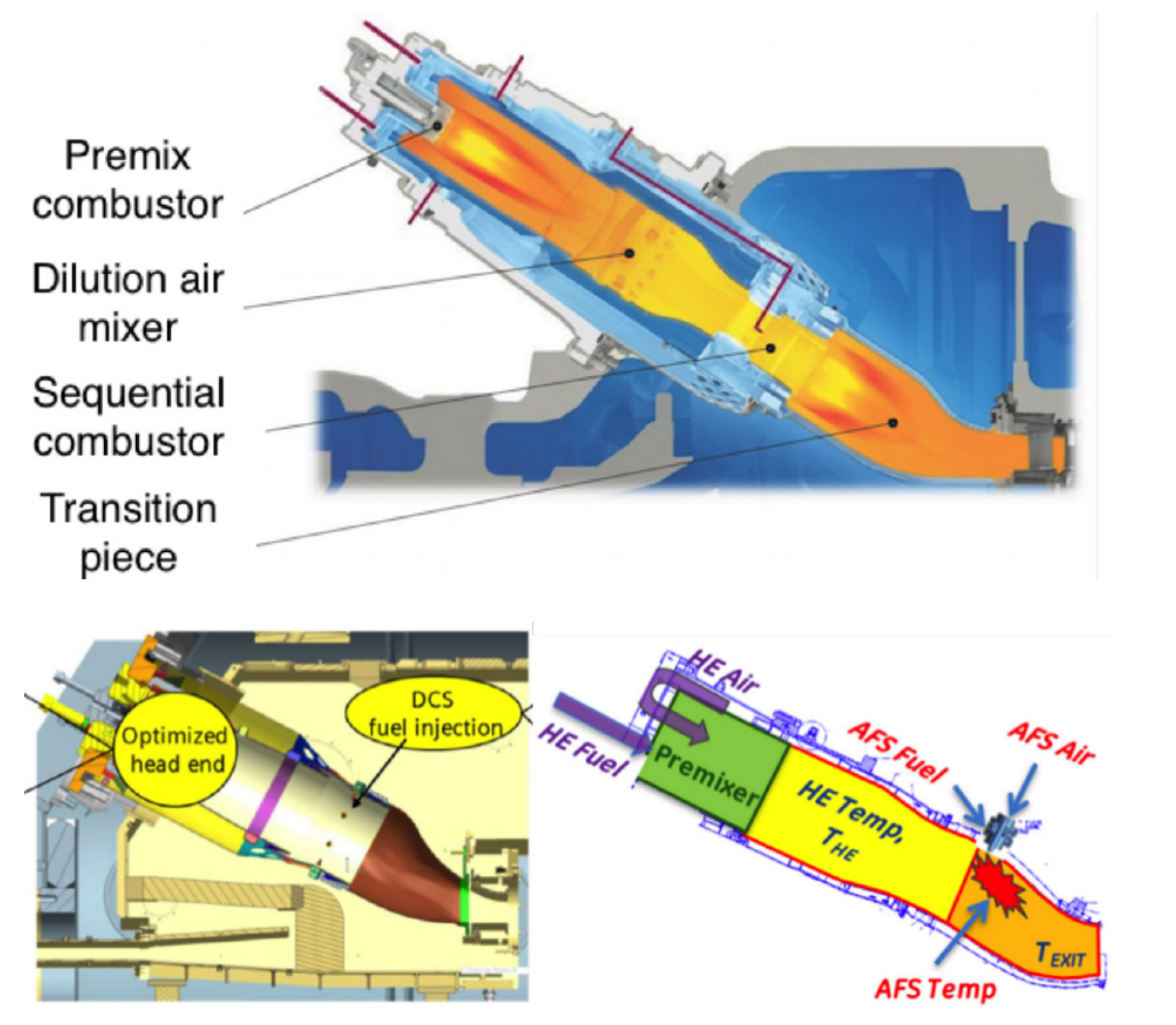
Today, there are advanced forms of combustion in longitudinal/axial stages on the market (see Figure 15): the constant pressure sequential combustion (CPSC) by ANSALDO Energia, the distributed combustion system (DCS) by SIEMENS [95], and GE’s Axial Fuel Staging (AFS).
Sequential combustion was initially developed by ABB/ALSTOM to increase load (operational) flexibility and to increase efficiency at partial loads. A first application of sequential combustion is found in the GT24 and GT26 turbines [70] developed by ABB and ALSTOM, schematically described in Figure 16 and Figure 17. In these machines, there is, in cascade, a high-pressure combustor (EV, first stage), a high-pressure turbine, an afterburner operating at approximately 20 bar and 1300 K (SEV, second stage), and a low-pressure turbine.

3.4. Micro-Mixing

In the “micro-mixing” technology, a very rapid mixing between the fuel and oxidant and many small flames is obtained, using a large number of very small injectors [99]. The principle of this combustion technique was invented in Germany several years ago for aerospace applications. This technique is widely studied today to reduce NO x emissions for hydrogen combustion in “dry” conditions, i.e., without injections of water or steam.
The micro-mixing principle makes it possible to reduce the formation of nitrogen oxides by reducing the residence time of the reactants in the high-temperature areas by shortening the flame [96,100,101]. The basic idea is to distribute the heat release inside the turbine combustor, through a large number of very small flames, instead of a single conventional flame. The injectors are sized so that the speed of entry into the combustion chamber is greater than the flame speed, thus avoiding the phenomenon of flashback and anchoring of the flame near the injector itself. Moreover, the diameter of the holes is generally smaller than the quenching distance of the flame itself; this mitigates the risk of the flame anchor inside the tubes. The quenching distance for a flame, referred to as the case of a tube, is the diameter of the tube; the tube walls remove enough heat from the flame area, which is locally extinguished as it tries to spread inside it [102].
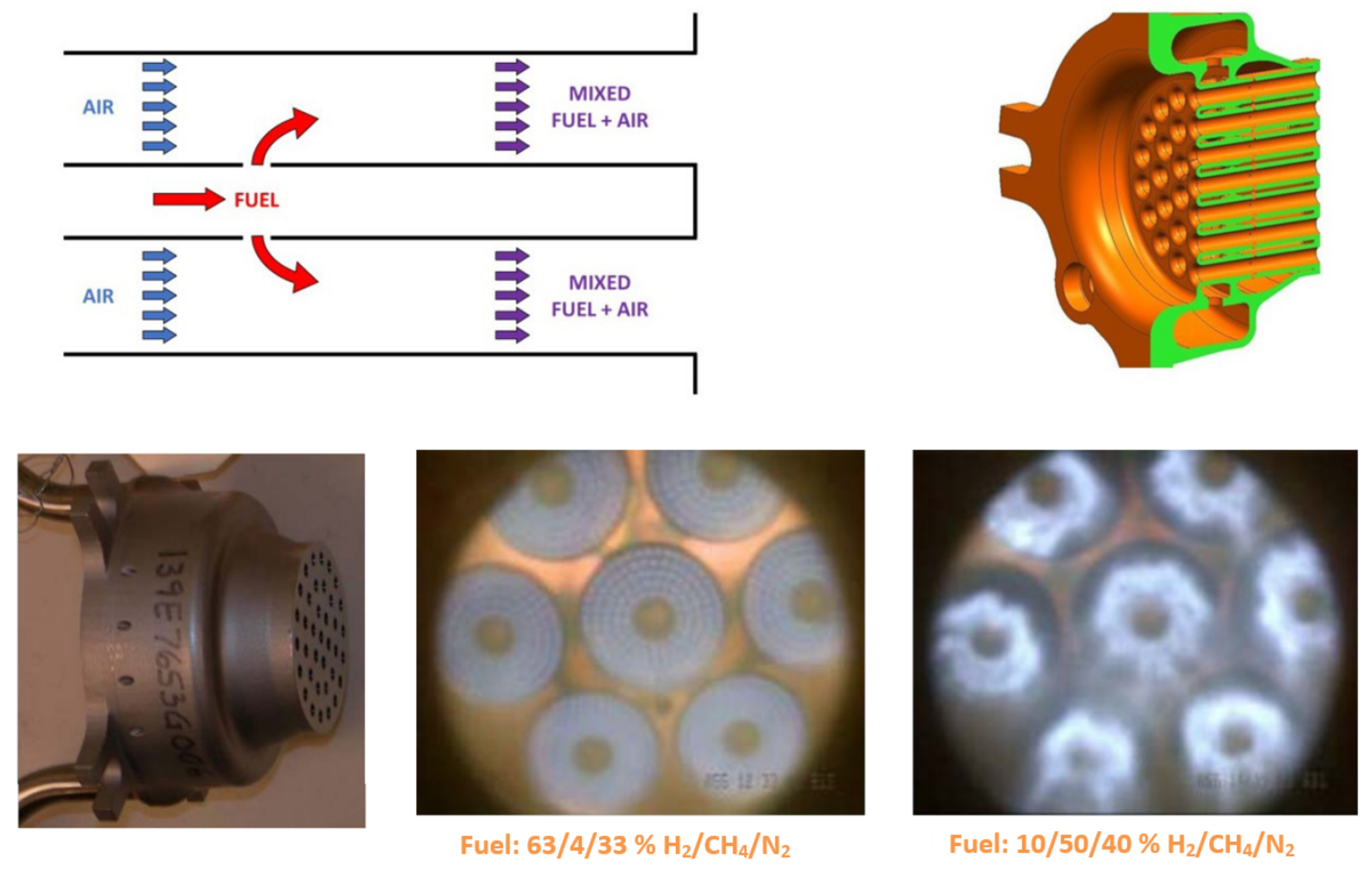
A very important property of the multi-pipe configuration is scalability, which allows for the design of combustors of different sizes, without significantly impacting the performance. This concept has been demonstrated at the research level [103], and by combustor manufacturers, through the development of full-scale prototypes both for the test phases and at a commercial level. Numerous studies have been done on possible configurations, including the “co-flow mixing”, “swirl-based mixing”, and “jet in cross-flow mixing” approach in multi-tube mixers [104], such as those shown in Figure 18. In all configurations, there are several small diameter injectors. The very small scales of these injectors require quite complex fuel and air supply systems.
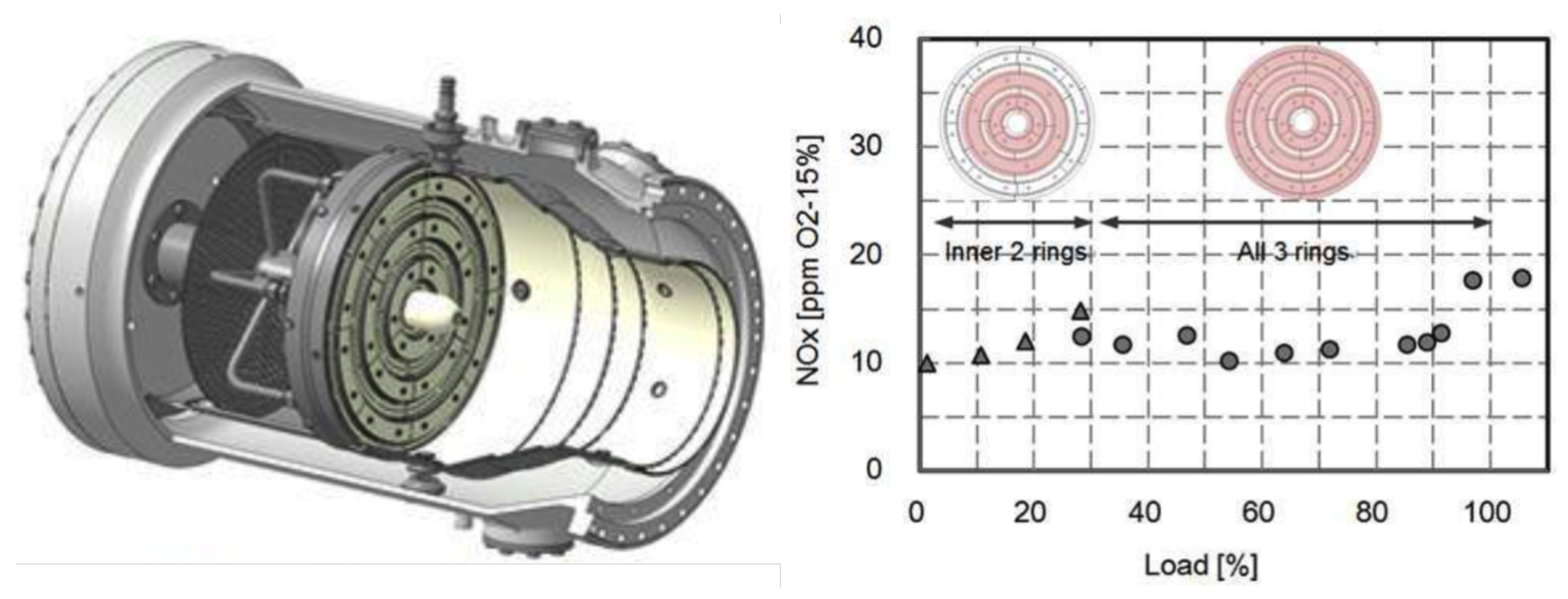
The KAWASAKI Heavy Industries burner, based on the Aachen University prototype, is proven to run on up to 100 % hydrogen in the M1A-17 gas turbine under commercial operating conditions [105]. The entire combustor is shown in Figure 19. According to the information released to the press, it seems that the machine supplied 1.1 MWe of power, with a reduction compared to the nominal natural gas power of 1.8 MWe, and about 2.8 MWt of available thermal power, with an electrical efficiency of 27 % ; the NO x production with this combustor (at two bar condition) remains below 20 ppm at 15 % O 2 for any workload, as shown in the same figure. The load variation is obtained through the ignition of the different rings (from idle to 30 % load conditions, inner two hydrogen rings were used and from 30 % load to full load conditions, all three rings were used).
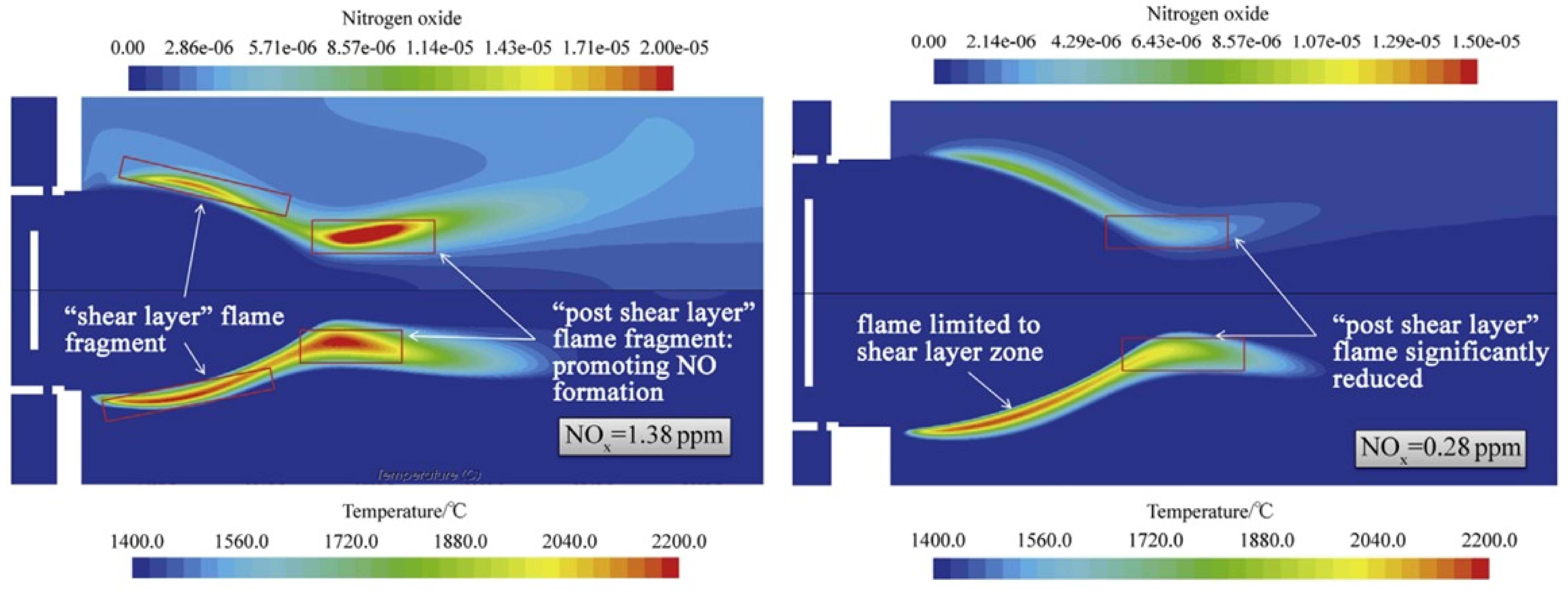
Figure 20 shows the working principle of the KAWASAKI micro-mix type combustion. Air flows through small openings and fuel is injected perpendicular to the air flow (cross flow configuration). The fuel/air mixture enters the combustion chamber forming an inner and an outer vortex that stabilize the flame. It has been found that the two key parameters that influence the flame shape and length, and then NO x formation (Figure 21), are the air flow blockage ratio and the depth of the fuel jet penetration into the air stream. The advantages of this configuration are the intrinsic safety in relation to the possibility of flashback, and the low NO x emission thanks to the very short residence times of the reactants in the micro-flames area.
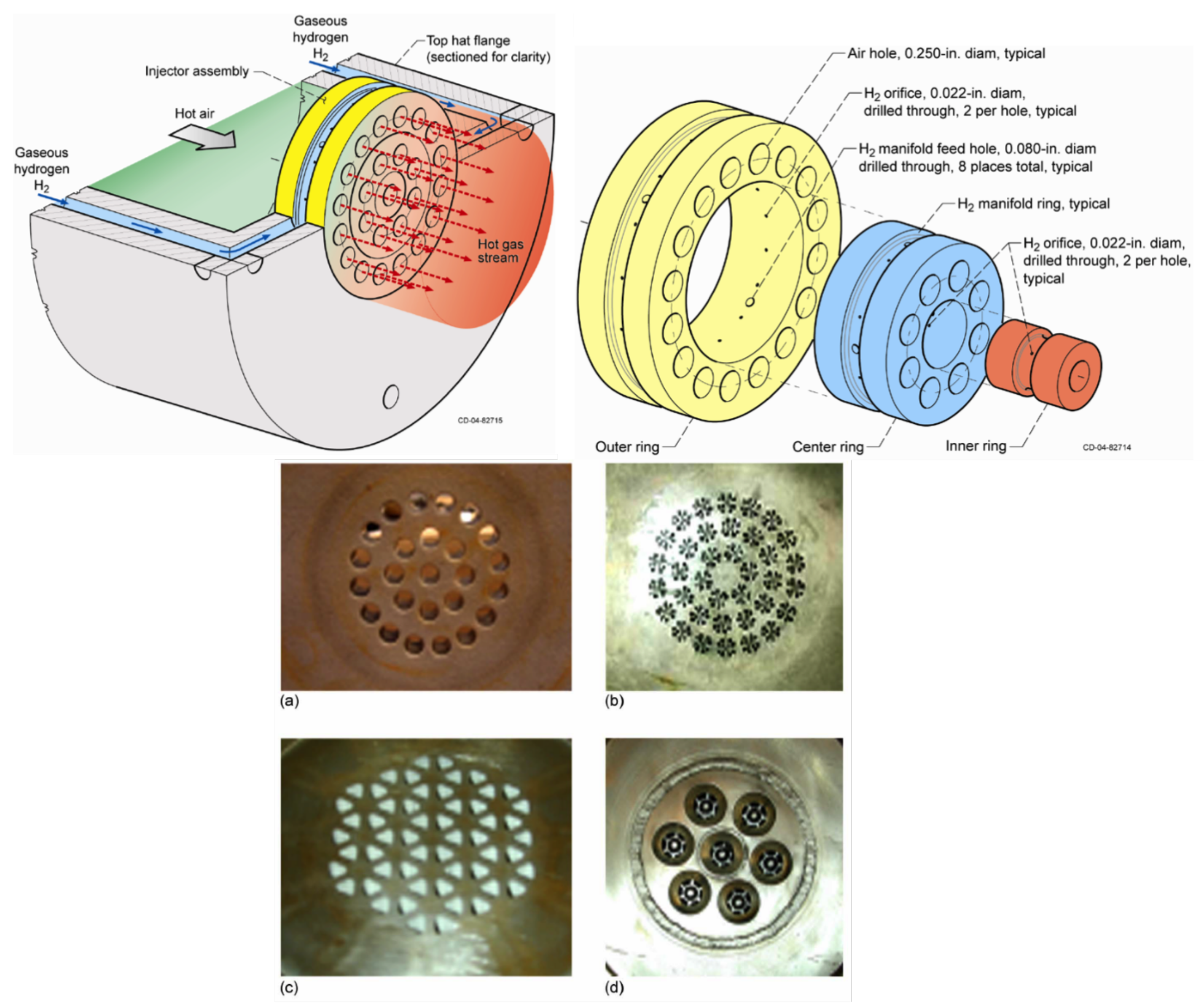
NASA also has been involved in the design of a Lean Direct Injection (LDI) multi-tube burner [107]. Figure 22 (Top left) reports the N1 burner. Air flows axially inside a multi-tube system through 25 injectors, while the hydrogen is introduced inside a fuel plenum and is injected into two opposing jets in each injector with a “cross flow” configuration [108]. The diameters of the air elements and of the hydrogen injection holes are 0.00635 m and 0.000508 m , respectively. It operates in a lean-burn regime and promotes the rapid mixing of fuel and air.
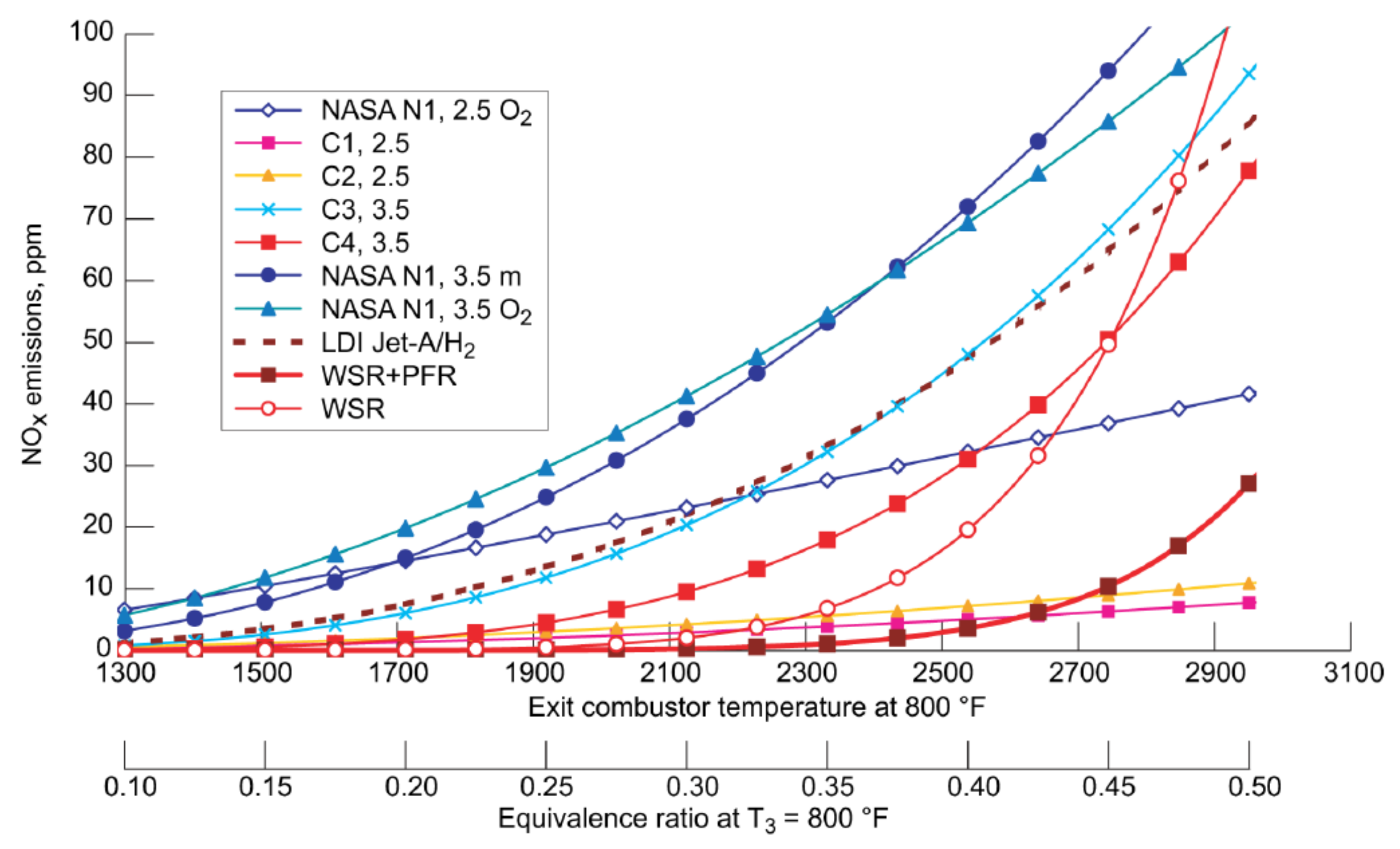
Several designs have been tested as shown in Figure 22 (bottom). Configuration C1 (Figure 22b) is composed of a central “+” shaped hydrogen jet, surrounded by eight angled air jets. To facilitate ignition, the fuel and the inner four air jets form a rich mixture, which is quenched downstream by the additional outer four jets. Configuration C2 (Figure 22c) is similar to the N1 injector design and it uses triangle holes instead of circles that maximize packing. Hydrogen is injected on each edge of the triangle to increase penetration and improve mixing. In configuration C3 (Figure 22d), hydrogen has a single center nozzle, with swirled air jets around it. Configuration C4 is based on C3 and it has four points of fuel injections, and swirl is not present, with respect to C3. All configurations have performed well in terms of emission (see Figure 23), stability and flashback, or autoignition, although construction and cooling difficulties have been highlighted. The C4 configuration has demonstrated a better performance than the other ones from a low NO x and durability criteria, thanks to multiple fuel injection points.
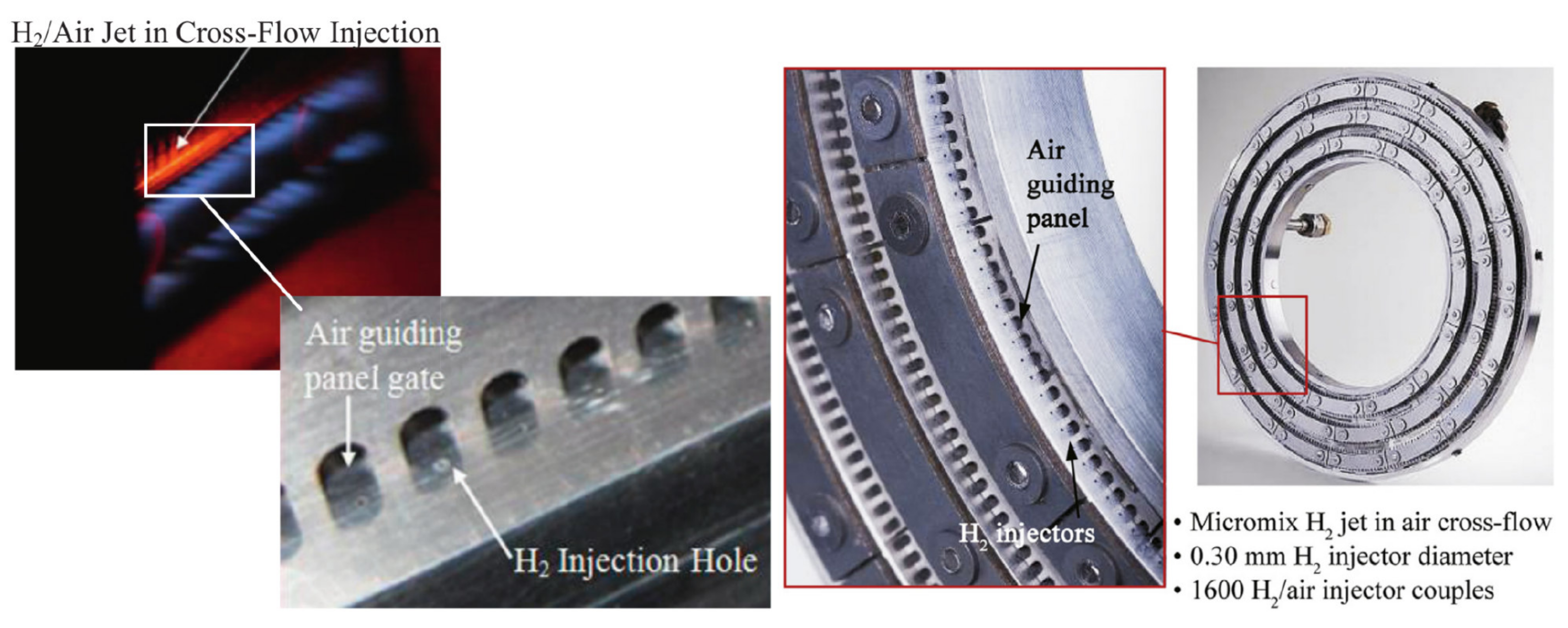
Figure 24 illustrates a small auxiliary power unit (APU) designated as GTCP36-300, which employs the micro-mixing concept. It comprises 1600 miniature injectors and requires approximately 1600 kW of hydrogen ( H 2 ) firing to generate 335 kW of shaft power. The micro-mixing burner has been seamlessly integrated into an annular reverse-flow combustion chamber, as detailed in [106,109]. Furthermore, research has indicated that this micro-mixing (MM) combustor is not only capable of operating efficiently on hydrogen-rich syngas at a medium pressure of 0.6 MPa, as demonstrated in [110], but it also exhibits the ability to run on pure hydrogen while maintaining low NO x emissions, as highlighted in [111]. Several experimental and numerical studies have evaluated the effects of changing the fuel injector diameter on flame structure, and NO x emissions in low/high-energy density burner configurations [100,112].
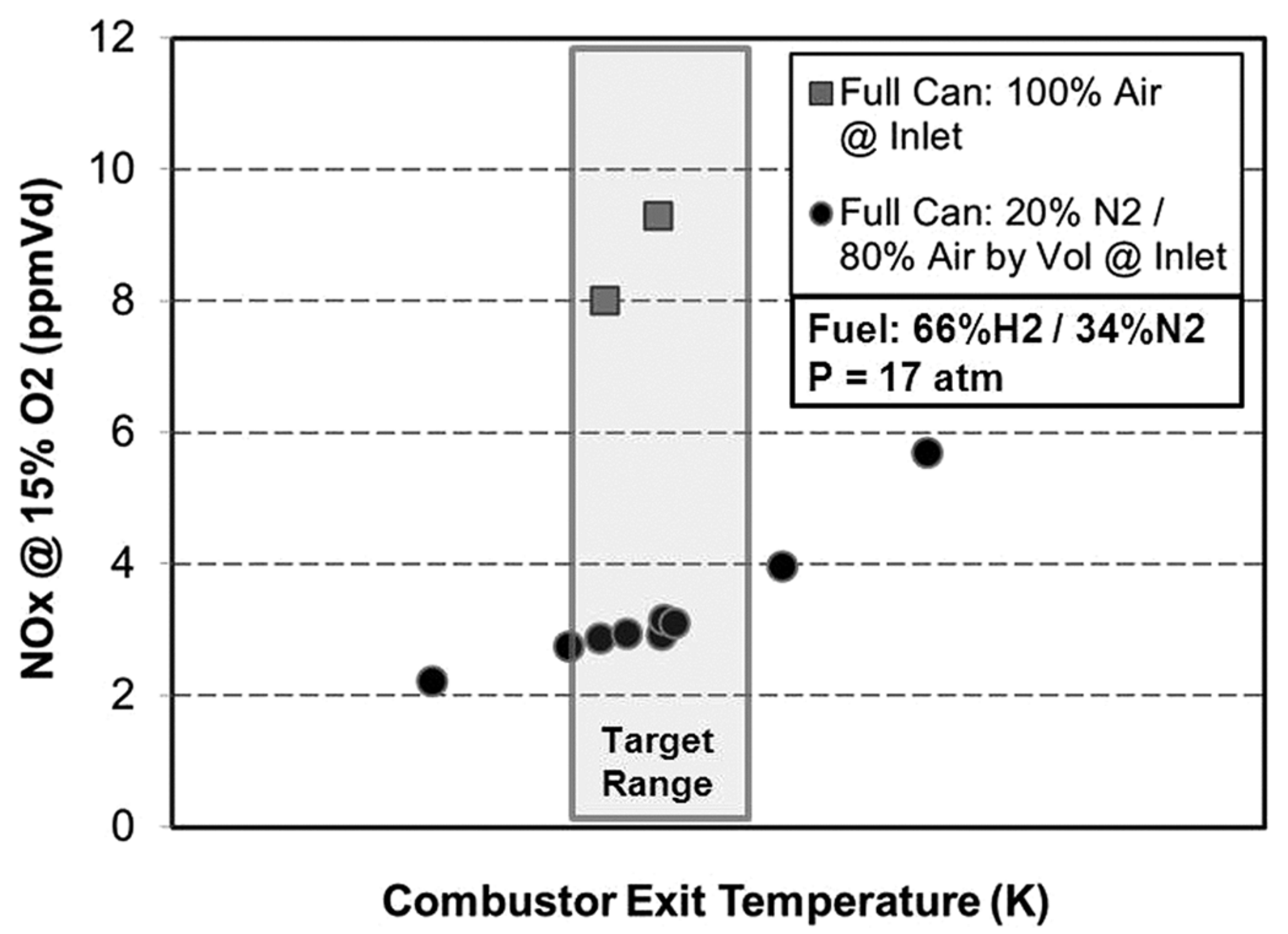
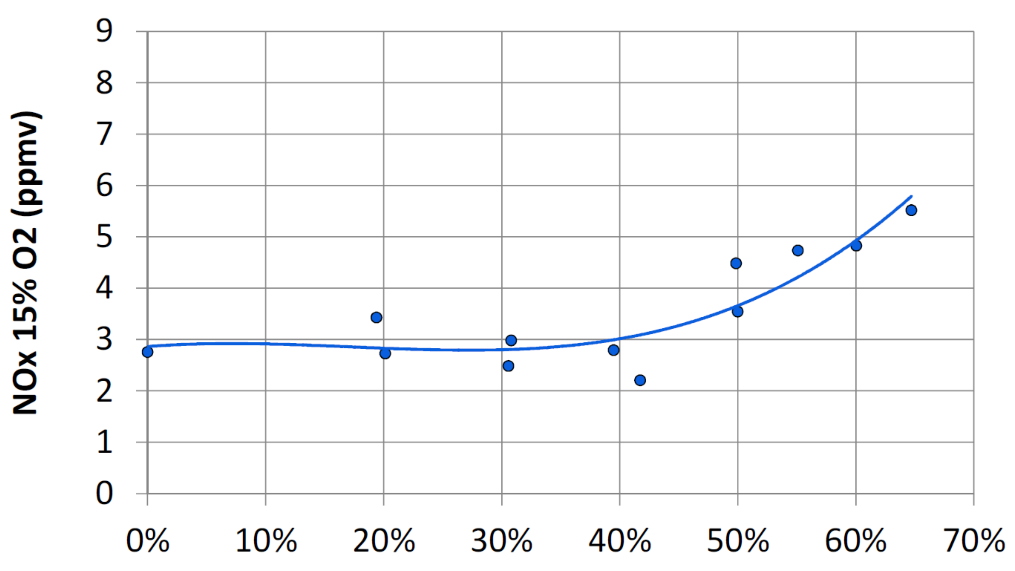
GE has designed the DLN 2.6e multi-pipe mixer system (Figure 25), with fuel injections in a crossflow configuration [113]. In this mixer, air flows through numerous channels arranged in parallel, with a toroidal fuel plenum surrounding them. Fuel is injected radially into the airflow through small holes drilled in the tube walls. The distance between the fuel injection point and the combustion chamber inlet may depend on fuel composition and machine operating conditions. Also, in this case, given the small diameter of the pipes, the air speed is greater than the flame speed, avoiding the flashback risk even with mixtures with a high hydrogen content. At the same time, due to the short tube length, a low pressure drop is measured. The DLN 2.6e burner was operated in a test facility under class H conditions up to 50 % vol of hydrogen, performing very well in terms of pollutant emissions (Figure 26). The multitube mixer concept was implemented in a full-can combustion system specifically designed for high-hydrogen fuel applications. The scaling up to a multinozzle combustor was carried out successfully, accumulating more than 100 h of operational experience with over 90% hydrogen content in the reactants. When using a fuel composed of 60% hydrogen and 40% nitrogen (by volume), the combustion system achieved NO x emissions below 10 ppm content (corrected to 15% O 2 ). With the inclusion of 20% extra nitrogen by volume in the inlet fluid, NO x levels as low as sub-3 ppm were measured, considering a 15% oxygen concentration. These results demonstrate the effectiveness of the approach, utilizing small-scale, jet-in-crossflow mixing within tubes, as a robust and low- NO x method for combusting high-hydrogen fuels in advanced gas turbine systems, as discussed in [113].
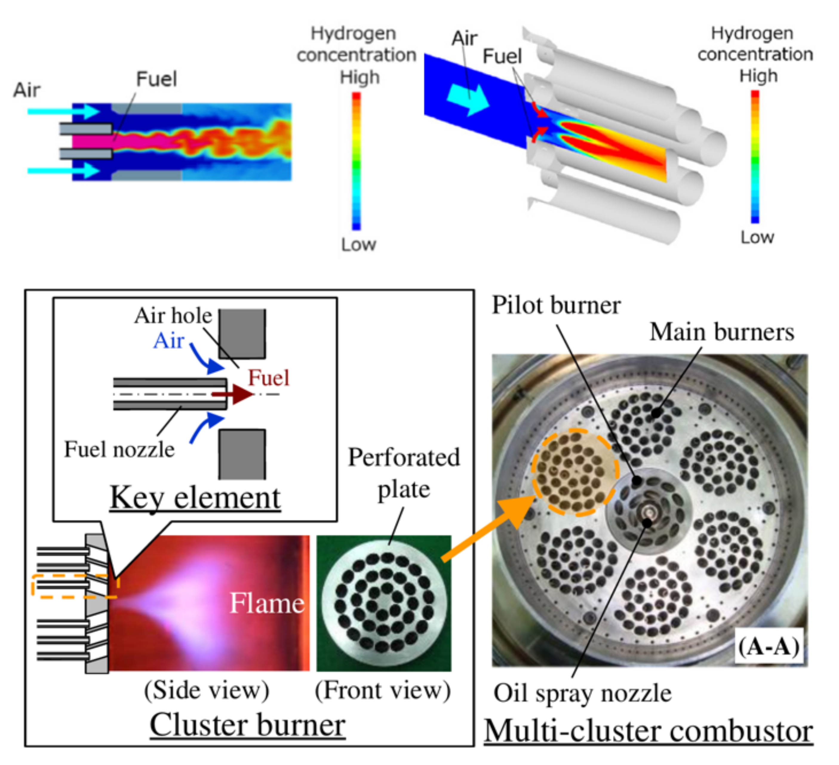
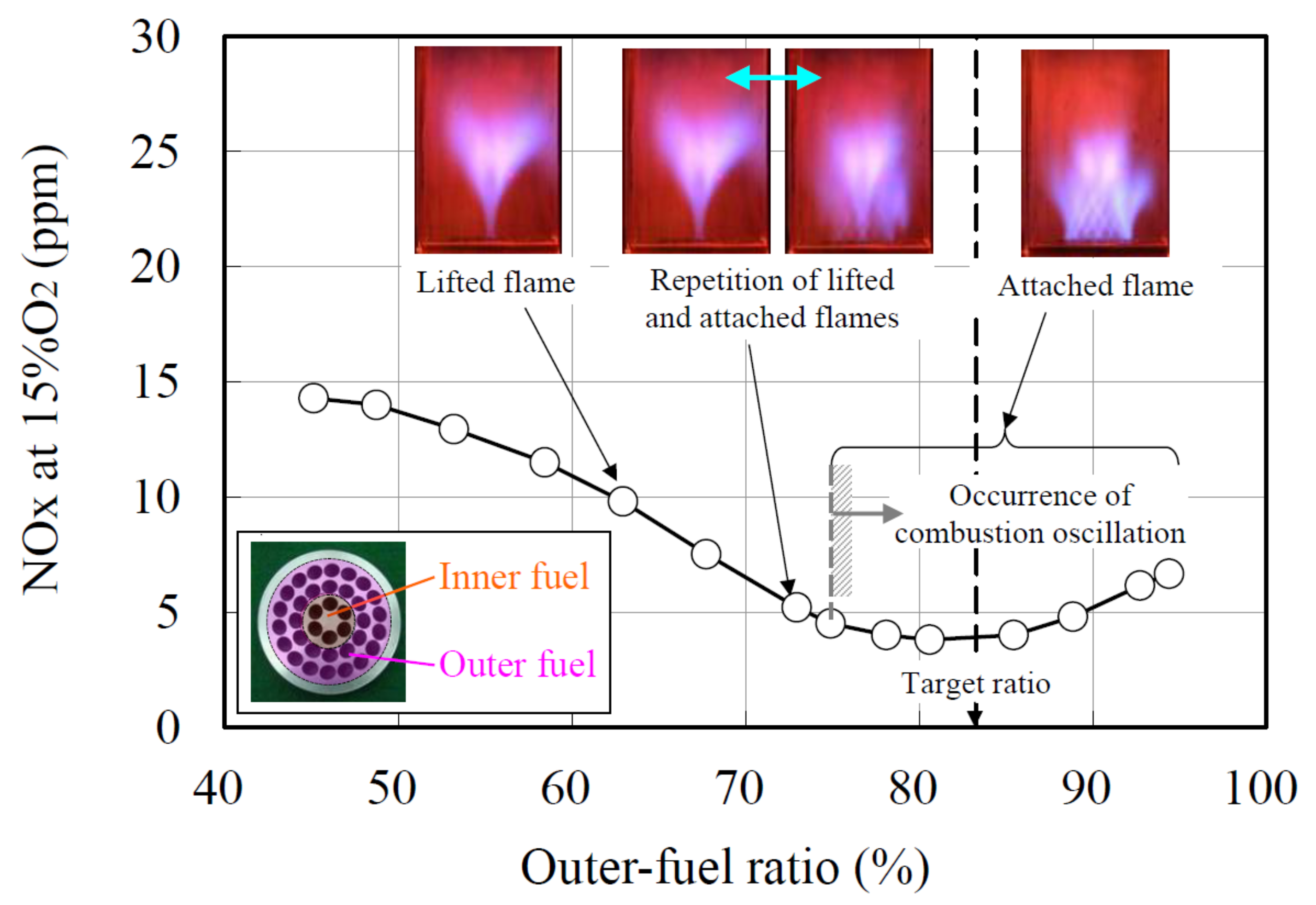
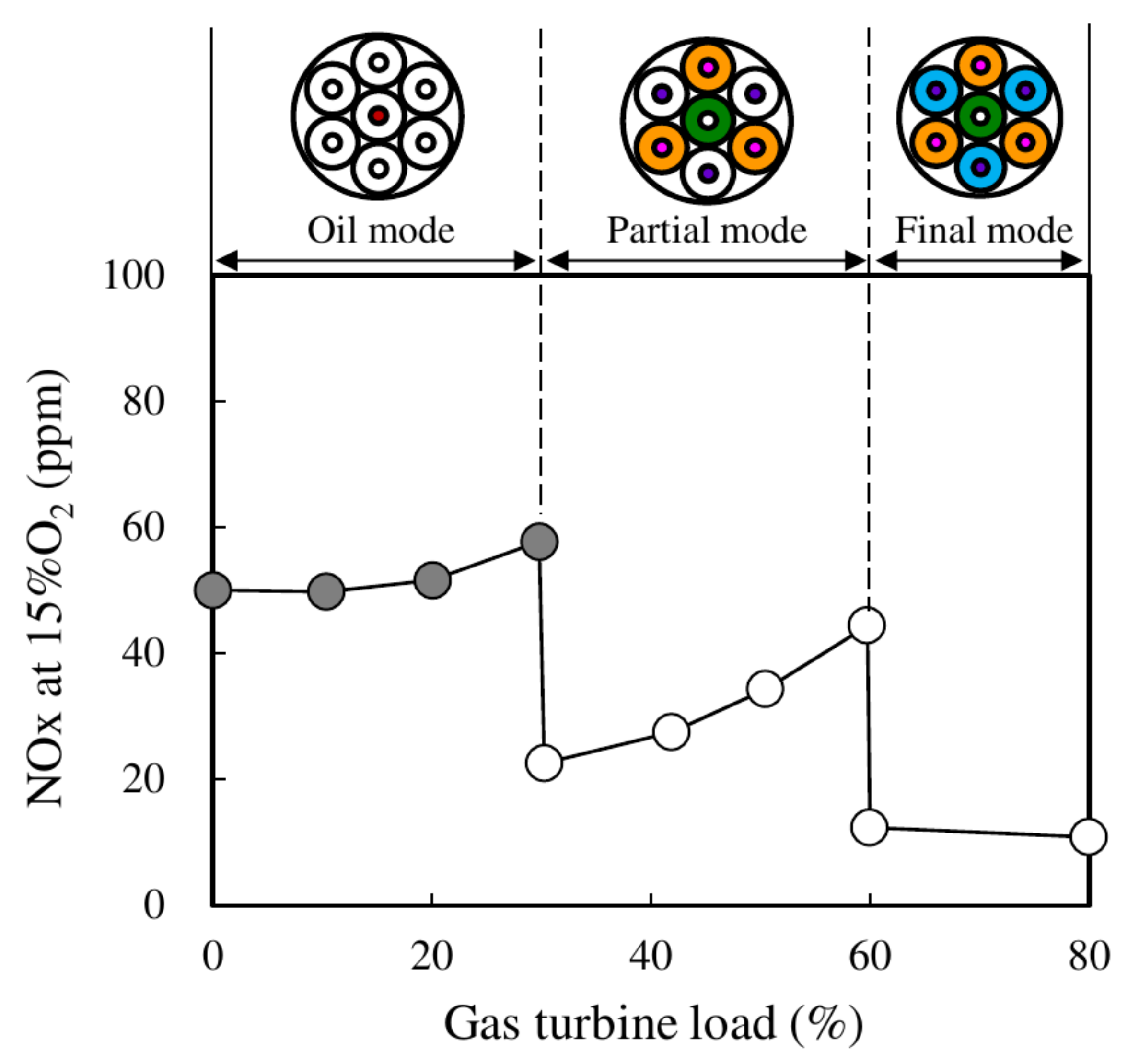
The MITSUBISHI-HITACHI group has designed a dry low NO x , flashback resistant, fuel-flexible combustor [114,115]. The combustor consists of multiple clusters, each composed of a certain number of fuel nozzles and air holes, arranged coaxially or in crossflow (Figure 27). Each cluster forms one flame. For each cluster, the jets are oriented to produce a converging and diverging swirl flow that lifts the flame. Moreover, the burner is equipped with a pilot in the center, which increases combustion stability. The burner combines both the advantage of low- NO x premixed combustion and the advantage of a flashback-resistant diffusion flame. In fact, in the single jet, fuel and air are partially premixed in a short section. Premixing completes downstream of the jet exit before the mixture is ignited. The short premixing section, together with the air-stream-surrounded fuel jet (in the case of coaxial jet) and the lifted flame, make the burner flashback resistant. The test results demonstrated the feasibility of achieving low NO x emissions with high hydrogen content fuels. The fuel can be distributed between the inner and outer nozzles of the cluster. The distribution ratio among the inner and outer circuit affects the burner performance, as the outer part suppresses NO x while the inner part increases stability (Figure 28). The system is started with oil fuel, using the central pilot. When a certain load is reached, the inner part of the main burners and the outer part of only three of them are activated (Figure 29). Subsequently, the remaining parts are fueled to reach the full load. It has been demonstrated that the choice of a convex rather than a flat perforated plate is a valid solution to suppress pressure oscillations, as it is able to move the flame away from the plate, reduce the wake region, and create a flow along the plate, delaying mixture ignition. As a result of the increased mixing distance, NO x is also reduced. MITSUBISHI-HITACHI [115] guarantees 30 %   H 2 by volume and aims at 100 % .

3.5. Exhaust Gas Recirculation

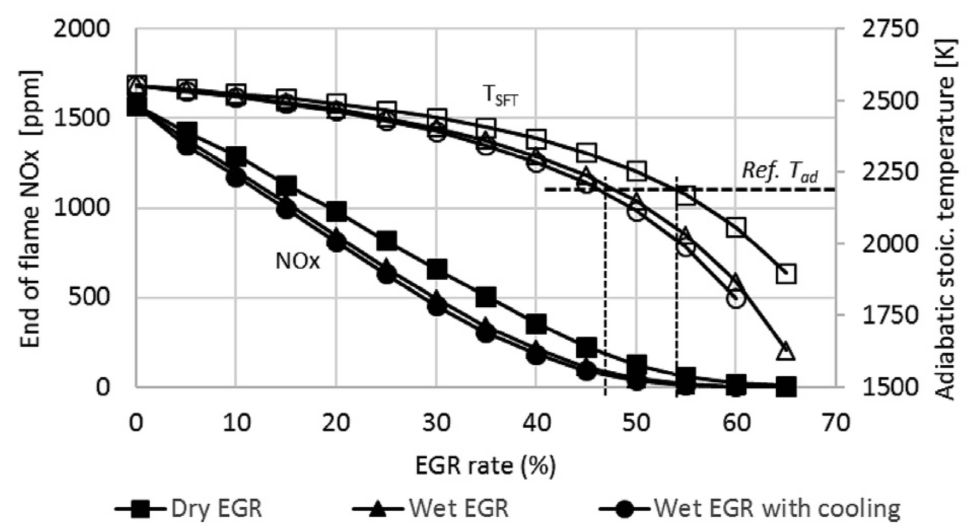
All the technologies described above can be integrated with flue gas recirculation. Exhaust Gas Recirculation (EGR) consists of recirculating part of the exhausted gases by mixing them with the air at the compressor intake [116,117]. This causes combustion in air substantially diluted in CO 2 and H 2 O , called “stale” air. The final effect can be analogous to that of MILD combustion for sufficiently high temperatures of the stale air [83]; the exhausted gases are recirculated (not with an internal recirculation of the combustor) in the reaction zone, and the consequent dilution reduces the local temperature peaks, slows down the formation of thermal NO x , and tends to dampen any thermo-acoustic instabilities [118,119,120,121]. It is observed that the production of nitrogen oxides is also significantly reduced at partial loads; consequently, EGR can also be adopted as a control strategy for gas turbines to increase their operational flexibility (i.e., load-flexibility) by reducing the minimum technical environmental load and, consequently, the operating costs related to the parking load during flexible operation. Wang et al. [122] found that water vapor in EGR has both physical and chemical effects on the laminar burning velocity of hydrogen-air mixtures. Increasing the water vapor fraction in EGR could suppress the NO x formation. However, the unburnt H 2 emission in the final products increases with the water vapor fraction. In the context of gas turbine applications, EGR is only known to have been applied in two specific cases related to CO 2 capture. One application involves increasing the CO 2 concentration in the exhaust gases of natural gas combined cycles (NGCC) [123] to enhance the efficiency of post-combustion CO 2 capture [124]. The capture plant modules are smaller, and the process capture is more effective and economically more advantageous. This is certainly true in a steady-state operating context, where there are no substantial load variations; however, the real applicability of current CCS technologies on gas turbines remains questionable in a flexible operating context [125]. The other application is within the oxy-fuel CO 2 capture scheme, where CO 2 replaces air as the working fluid for the gas turbine, resulting in a semi-closed cycle [126]. Surprisingly, there is little scientific literature evaluating the use of EGR in power cycles fueled by hydrogen. Ditaranto et al. [116,127] studied exhaust gas recirculated (dry, wet, and wet EGR with cooling) in a gas turbine burning hydrogen. They found a gain in efficiency: the EGR rate needs to be at least 45% and 55% in the wet and dry EGR, respectively, to meet the same adiabatic flame temperature as in the reference case (IGCC power plant with pre-combustion carbon capture with nitrogen dilution; Table 1 in [116]). Kinetic calculations in laminar conditions with fuel, air input compositions, and temperature of the analyzed process cycle are shown in Figure 30 for different EGR rates resulting in an NO x concentration smaller than 100 ppm for an EGR value greater than 45%.
The work of Wrinkler et al. [128] is relevant, as it performed high-pressure experiments in a short contact time honeycomb-subscale gas turbine reactor with high exhaust gas recirculation in a mixture of methane doped with 20 % mol hydrogen. They found that the addition of hydrogen therefore helps the CO emission level without having a detrimental impact on NO x emission for a representative range of adiabatic flame temperatures.

4. Conclusions

Within the thermo-electric generation sector, gas turbines will continue to play a pivotal role in the worldwide energy landscape. They serve as a valuable complement to renewable energy sources and benefit from a substantial existing installed base. These turbines are tasked with providing backup services, both seasonally and during peak demand periods, to support the stability of variable renewable energy sources and maintain the reliability of the electrical grid. Their contribution to enhancing the flexibility of the electrical system is anticipated by the International Energy Agency to remain significant even in a projection for the year 2040. The article presented a comprehensive review on hydrogen-blend gas turbine combustion technologies with their backgrounds, characteristics, and strategies, looking at solutions already available on the market and at those still under investigation and in the development phase. Current research and OEM interest is focusing on different approaches involving aerodynamic and self-ignition stabilization mechanisms, staging, and micro-mixing. From the analysis carried out, two technologies attract great interest for their fuel-flexibility and low- NO x emission features. One is the sequential combustion technology, implemented in the commercially available ANSALDO ENERGIA GT36, which has a certified capability to operate up to 70% of hydrogen and a strong potential to reach 100%. A sequential combustor in a gas turbine involves a combustion process that occurs in multiple stages or sequential combustion chambers. It offers advantages such as an enhanced combustion efficiency, emissions control, optimized hydrogen combustion, flame stability, high efficiency at part load, and fuel blending flexibility. However, it also presents challenges related to increased complexity, maintenance demands, pressure drops, thermal stresses, and requires the careful control and synchronization of fuel injection and combustion across stages, making the overall operation of the gas turbine more intricate and demanding in terms of control systems. The second one is the micro-mixing strategy, an emerging and promising technology, not yet at its commercial stage. Micro-mixing burners for hydrogen blends aim to enhance the mixing of hydrogen and air on a very small scale, to obtain many small flames, characterized by a low residence time and then low NO x emissions. Like sequential combustors, they offer advantages such as an improved combustion efficiency, emissions reduction, optimized hydrogen utilization, fuel-flexibility enhancement, reduction of flashback risk, and high scalability potential (i.e., it can be implemented on machines of very different sizes). In this context, some producers have moved towards premixed systems while others have moved towards partially premixed or diffusive systems. Apart from new machines, the market also offers some retrofit solutions that give users the possibility to improve the fuel-flexibility of some machines in their fleet. In the end, despite the extensive historical use of gas turbines in various industries, there is a need for further research and development to ensure their reliable and safe operation when utilizing higher hydrogen content, aiming to achieve a minimum of 80% by volume for a substantial reduction in CO 2 emissions.

Author Contributions

D.C.: Conceptualization, Original draft preparation and writing, Investigation, Writing—Review & Editing. E.G.: Writing—Review & Editing. A.D.N.: Writing—original draft, Writing—Review & Editing. G.C.: Writing—Review & Editing. All authors have read and agreed to the published version of the manuscript.

Funding

This review study was performed within the Italian project “Tecnologie dell’Idrogeno” (“Hydrogen Technologies”), funded by the Italian Ministry of Environment and Energy Security (MiTE): Program Agreement MiTE-ENEA on Electric System Research, PTR22-24, Research Topic 1.3, WP3, LA3.6.

Data Availability Statement

Not applicable.

Conflicts of Interest

The authors declare no conflict of interest.

References

  1. Russ, M. Cost-effective strategies for an optimised allocation of carbon dioxide emission reduction measures. In Unwelttechnik; Verlag-Shaker: Aachen, Germany, 1994. [Google Scholar]
  2. Ausfelder, F.; Bazzanella, A. Hydrogen in the chemical industry. In Hydrogen Science and Engineering: Materials, Processes, Systems and Technology; John Wiley & Sons: Hoboken, NJ, USA, 2016. [Google Scholar]
  3. Karakaya, E.; Nuur, C.; Assbring, L. Potential transitions in the iron and steel industry in Sweden: Towards a hydrogen based future? J. Clean. Prod. 2018, 195, 651–663. [Google Scholar] [CrossRef]
  4. Otto, A.A.; Robinius, M.; Grube, T.; Schiebahn, S.; Praktiknjo, A.; Stolten, D. Power-to-steel: Reducing CO2 through the integration of renewable energy and hydrogen into the German steel industry. Energies 2017, 10, 451. [Google Scholar] [CrossRef]
  5. International Energy Agency. World Energy Outlook. pp. 1–810. Available online: https://www.iea.org/reports/world-energy-outlook-2019 (accessed on 16 August 2023).
  6. Giacomazzi, E.; Messina, G. Hydrogen and the Fuel-Flexibility Dilemma in Gas Turbines. In Energia, Ambiente e Innovazione; ENEA: Stockholm, Sweden, 2021; Volume 1, pp. 125–129. [Google Scholar]
  7. Kumar, A.; Singh, R.; Sinha, A.S.K. Catalyst modification strategies to enhance the catalyst activity and stability during steam reforming of acetic acid for hydrogen production. Int. J. Hydrog. Energy 2019, 44, 12983–13010. [Google Scholar] [CrossRef]
  8. Shiva, K.S.; Himabindu, V. Hydrogen production by PEM water electrolysis-a review. Mater. Sci. Energy Technol. 2019, 2, 442–454. [Google Scholar]
  9. Chi, J.; Yu, H. Water electrolysis based on renewable energy for hydrogen production. Chin. J. Catal. 2018, 39, 390–394. [Google Scholar] [CrossRef]
  10. Nahar, G.; Mote, D.; Dupont, V. Hydrogen production from reforming of biogas:review of technological advances and an Indian perspective. Renew. Sustain. Energy Rev. 2017, 76, 1032–1052. [Google Scholar] [CrossRef]
  11. Mishra, P.; Krishnan, S.; Rana, S.; Singh, L.; Sakinah, M.; Wahid, A.Z. Outlook of fermentative hydrogen production techniques: An overview of dark, photo and integrated dark photo fermentative approach to biomass. Energy Strateg. Rev. 2019, 24, 27–37. [Google Scholar] [CrossRef]
  12. Pandey, Y.K.B.; Prajapati, P.N. Sheth, Recent progress in thermochemical techniques to produce hydrogen gas from biomass: A state of the art review. Int. J. Hydrog. Energy 2019, 44, 25384–25415. [Google Scholar] [CrossRef]
  13. Wang, J.; Yin, Y. Fermentative hydrogen production using various biomass-based materials as feedstock. Renew. Sustain. Energy Rev. 2019, 92, 284–306. [Google Scholar] [CrossRef]
  14. Basheer, A.A.; Ali, I. Water photo splitting for green hydrogen energy by green nanoparticles. Int. J. Hydrog. Energy 2019, 44, 11564–11573. [Google Scholar] [CrossRef]
  15. Kadier, A.; Kalil, M.S.; Abdeshahian, P.; Chandrasekhar, K.; Mohamed, A.; Azman, N.F.; Logroño, W.; Simayi, Y.; Hamid, A.A. Recent advances and emerging challenges in microbial electrolysis cells (MECs) for microbial production of hydrogen and value-added chemicals. Renew. Sustain. Energy Rev. 2016, 61, 501–525. [Google Scholar] [CrossRef]
  16. L’Orange Seigo, S.; Dohle, S.; Siegrist, M. Public Perception of Carbon Capture and Storage (CCS): A Review. Renew. Sustain. Energy Rev. 2014, 38, 848–863. [Google Scholar] [CrossRef]
  17. Carbon Capture and Storage Association (CCSA). What is CCS? CCSA: London, UK, 2020; Available online: https://www.ccsassociation.org/ (accessed on 20 August 2023).
  18. Black, S.; Roll, P.; Grames, M.; Goodwin, M.; Biccum, J.; Legault, R.; Soares, B.; Dorman, D. Dual Fuel Direct Ignition Burners. U.S. Patent 20190162410 A1, 30 May 2019. [Google Scholar]
  19. Richards, G.A.; McMillian, M.M.; Gemmen, R.S.; Rogers, W.A.; Cully, S.R. Issues for Low-Emission, Fuel-Flexible Power Systems. Prog. Energy Combust. Sci. 2001, 27, 141–169. [Google Scholar] [CrossRef]
  20. Döbbeling, K.; Hellat, J.; Koch, H. 25 Years of BBC/ABB/ Alstom Lean Premix Combustion Technologies. J. Eng. Gas Turbines Power 2007, 129, 2–12. [Google Scholar] [CrossRef]
  21. Davis, L.B.; Black, S.H. Dry Low NOx Combustion Systems for GE Heavy-Duty Gas Turbines; GER-3568G; GE Power Systems: Schenectady, NY, USA, 2000. [Google Scholar]
  22. Clean Hydrogen Partnership. Clean Hydrogen Joint Undertaking, Strategic Research and Innovation Agenda 2021–2027, Annex to GB decision no. CleanHydrogen-GB-2022-02. Available online: https://www.clean-hydrogen.europa.eu (accessed on 23 August 2023).
  23. ETN Global. Addressing the Combustion Challenges of Hydrogen Addition to Natural Gas. 2022. Available online: https://etn.global/tag/news/ (accessed on 25 August 2023).
  24. York, W.D.; Ziminsky, W.S.; Yilmaz, E. Development and Testing of a Low NOx Hydrogen Combustion System for Heavy Duty Gas Turbines. In Proceedings of the ASME Turbo Expo 2012: Turbine Technical Conference and Exposition, Copenhagen, Denmark, 11–15 June 2012; pp. 1395–1405. [Google Scholar]
  25. Taamallah, S.; Vogiatzaki, K.; Alzahrani, F.M.; Mokheimer, E.M.; Habib, M.A.; Ghoniem, A.F. Fuel Flexibility, Stability and Emissions in Premixed Hydrogen-Rich Gas Turbine Combustion: Technology, Fundamentals, and Numerical Simulations. Appl. Energy 2015, 154, 1020–1047. [Google Scholar] [CrossRef]
  26. Du Toit, M.H.; Avdeenkov, A.V.; Bessarabov, D. Reviewing H2 Combustion: A Case Study for Non-Fuel-Cell Power Systems and Safety in Passive Autocatalytic Recombiners. Energy Fuels 2018, 32, 6401–6422. [Google Scholar] [CrossRef]
  27. Tang, C.; Zhang, Y.; Huang, Z. Progress in combustion investigations of hydrogen enriched hydrocarbons. Renew. Sustain. Energy Rev. 2014, 30, 195–216. [Google Scholar] [CrossRef]
  28. Azazul Haque, M.; Nemitallah, M.A.; Abdelhafez, A.; Mansir, I.B.; Habib, M.A. Review of Fuel/Oxidizer-Flexible Combustion in Gas Turbines. Energy Fuels 2020, 34, 10459–10485. [Google Scholar] [CrossRef]
  29. Nemitallah, M.A.; Abdelhafez, A.A.; Ali, A.; Mansir, I.; Habib, M.A. Frontiers in Combustion Techniques and Burner Designs for Emissions Control and CO2 Capture: A Review. Int. J. Energy Res. 2019, 43, 7790–7822. [Google Scholar]
  30. Zhen, H.S.; Leung, C.W.; Cheung, C.S.; Huang, Z.H. Characterization of biogas-hydrogen premixed flames using Bunsen burner. Int. J. Hydrog. Energy 2014, 39, 13292–13299. [Google Scholar] [CrossRef]
  31. Kim, H.S.; Arghode, V.K.; Gupta, A.K. Flame Characteristics of Hydrogen-Enriched Methane-Air Premixed Swirling Flames. Int. J. Hydrog. Energy 2009, 34, 1063–1073. [Google Scholar] [CrossRef]
  32. Tang, C.; Huang, Z.; Jin, C.; He, J.; Wang, J.; Wang, X.; Miao, H. Laminar Burning Velocities and Combustion Characteristics of Propane-Hydrogen-Air Premixed Flames. Int. J. Hydrog. Energy 2008, 33, 4906–4914. [Google Scholar] [CrossRef]
  33. Hu, E.; Huang, Z.; He, J.; Jin, C.; Zheng, J. Experimental and Numerical Study on Laminar Burning Characteristics of Premixed Methane-Hydrogen-Air Flames. Int. J. Hydrog. Energy 2009, 34, 4876–4888. [Google Scholar] [CrossRef]
  34. Gersen, S.; Anikin, N.B.; Mokhov, A.V.; Levinsky, H.B. Ignition Properties of Methane/Hydrogen Mixtures in a Rapid Compression Machine. Int. J. Hydrog. Energy 2008, 33, 1957–1964. [Google Scholar] [CrossRef]
  35. Park, S. Hydrogen addition effect on NO formation in methane/air lean-premixed flames at elevated pressure. Int. J. Hydrog. Energy 2021, 46, 25712–25725. [Google Scholar] [CrossRef]
  36. Sankaran, R.; Im, H.R. Effects of Hydrogen Addition on the Markstein Length and Flammability Limit of Stretched Methane/Air Premixed Flames. Combust. Sci. Technol. 2006, 178, 1585–1611. [Google Scholar] [CrossRef]
  37. Imteyaz, B.A.; Nemitallah, M.A.; Abdelhafez, A.A.; Habib, M.A. Combustion Behavior and Stability Map of Hydrogen-Enriched Oxy-Methane Premixed Flames in a Model Gas Turbine Combustor. Int. J. Hydrog. Energy 2018, 43, 16652–16666. [Google Scholar] [CrossRef]
  38. Nemitallah, M.A.; Imteyaz, B.; Abdelhafez, A.; Habib, M.A. Experimental and Computational Study on Stability Characteristics of Hydrogen-Enriched Oxy-Methane Premixed Flames. Appl. Energy 2019, 250, 433–443. [Google Scholar] [CrossRef]
  39. Janus, M.C.; Richards, R.A.; Yip, M.J.; Robey, E.H. Effects of Ambient Conditions and Fuel Composition on Combustion Stability. In Proceedings of the 1997 American Society of Mechanical Engineers (ASME)/International Gas Turbine Institute (IGTI) Turbo Expo Meeting, Orlando, FL, USA, 2–5 June 1997; p. 13. [Google Scholar]
  40. Figura, L.; Lee, J.G.; Quay, B.D.; Santavicca, D.A. The Effects of Fuel Composition on Flame Structure and Combustion Dynamics in a Lean Premixed Combustor. In Turbo Expo: Power for Land, Sea, and Air; ASMEDC: Montreal, QC, Canada, 2007; Volume 47918, pp. 181–187. [Google Scholar]
  41. Schefer, R.W.; Wicksall, D.M.; Agrawal, A.K. Combustion of Hydrogen-Enriched Methane in a Lean Premixed Swirl-Stabilized Burner. Proc. Combust. Inst. 2002, 29, 843–851. [Google Scholar] [CrossRef]
  42. Zhang, J.; Ratner, A. Experimental Study on the Excitation of Thermoacoustic Instability of Hydrogen-Methane/Air Premixed Flames under Atmospheric and Elevated Pressure Conditions. Int. J. Hydrog. Energy 2019, 44, 21324–21335. [Google Scholar] [CrossRef]
  43. Karlis, E.; Liu, Y.; Hardalupas, Y.; Taylor, A.M.K.P. H2 Enrichment of CH4 Blends in Lean Premixed Gas Turbine Combustion: An Experimental Study on Effects on Flame Shape and Thermoacoustic Oscillation Dynamics. Fuel 2019, 254, 115524. [Google Scholar] [CrossRef]
  44. Beita, J.; Talibi, M.; Sadasivuni, S.; Balachandran, R. Thermoacoustic Instability Considerations for High Hydrogen Combustion in Lean Premixed Gas Turbine Combustors: A Review. Hydrogen 2021, 2, 33–57. [Google Scholar] [CrossRef]
  45. Lieuwen, T.; Torres, H.; Johnson, C.; Zinn, B.T. A Mechanism for Combustion Instabilities in Premixed Gas Turbine Combustors. ASME J. Eng. Gas Turbines Power 2001, 123, 182–190. [Google Scholar] [CrossRef]
  46. Gonzalez-Juez, E.; Lee, J.G.; Santavicca, D.A. A Study of Combustion Instabilities Driven by Flame-Vortex Interactions. In Proceedings of the 41st AIAA/ASME/SAE/ASEE Joint Propulsion Conference & Exhibit, Tucson, AZ, USA, 10–13 July 2005. [Google Scholar]
  47. Lee, J.G.; Santavicca, D.A. Experimental Diagnostics for the Study of Combustion Instabilities in Lean Premixed Combustors. J. Propul. Power 2003, 19, 735–750. [Google Scholar] [CrossRef]
  48. LaPenna, P.E.; Berger, L.; Attili, A.; Lamioni, R.; Fogla, N.; Pitsch, H.; Creta, F. Data-driven subfilter modelling of thermo-diffusively unstable hydrogen-air premixed flames. Combust. Theory Model. 2021, 25, 1064–1085. [Google Scholar] [CrossRef]
  49. Lam, K.K.; Geipel, P.; Larfeldt, J. Hydrogen Enriched Combustion Testing of Siemens Industrial SGT-400 at Atmospheric Conditions. In Turbo Expo: Power for Land, Sea, and Air; ASME: Dusseldorf, Germany, 2014; pp. 1–10. [Google Scholar]
  50. Turbomachinery International. Available online: https://www.turbomachinerymag.com/view/solving-the-challenge-of-lean-hydrogen-premix-combustion-with-highly-reactive-fuels (accessed on 25 August 2023).
  51. Glarborg, P.; Miller, J.A.; Ruscic, B.; Klippenstein, S.J. Modeling nitrogen chemistry in combustion. Prog. Energy Combust. Sci. 2018, 67, 31–68. [Google Scholar] [CrossRef]
  52. Zeldovich, Y.B. The oxidation of nitrogen in combustion and explosions. Acta Physicochem. USSR 1946, 21, 577–628. [Google Scholar]
  53. Iverach, D.; Basden, K.S.; Kirov, N.Y. Formation of nitric oxide in fuel-lean and fuel-rich flames. Symp. (Int.) Combust. 1976, 14, 767–775. [Google Scholar] [CrossRef]
  54. Harris, R.J.; Nasralla, M.; Williams, A. Formation of oxides of nitrogen in high-temperature CH4-O2-N2 flames. Combust. Sci. Technol. 1976, 14, 85–94. [Google Scholar] [CrossRef]
  55. Richards, G.; Weiland, N.; Straket, P. The Gas Turbine Handbook; National Energy Technology Laboratory: Pittsburgh, PA, USA, 2006; pp. 203–208. [Google Scholar]
  56. Fenimore, C.P. Formation of nitric oxide in premixed hydrocarbon flames. Symp. (Int.) Combust. 1971, 13, 373–380. [Google Scholar] [CrossRef]
  57. Hayhurst, A.N.; Vince, I.M. Nitric-oxide formation from N2 in flames-the importance of prompt NO. Prog. Energy Combust. Sci. 1980, 6, 35–51. [Google Scholar] [CrossRef]
  58. Lamoureux, N.; El Merhubi, H.; Pillier, L.; de Persis, S.; Desgroux, P. Modeling of NO formation in low pressure premixed flames. Combust. Flame 2016, 163, 557–575. [Google Scholar] [CrossRef]
  59. Bozzelli, J.W.; Dean, A.M. O + NNH: A possible new route for NOx formation in flames. Int. J. Chem. Kinet. 1995, 27, 1097–1109. [Google Scholar] [CrossRef]
  60. Day, M.S.; Bell, J.B.; Gao, X.; Glarborg, P. Numerical simulation of nitrogen oxide formation in lean premixed turbulent H2/O2/N2 flames. Proc. Combust. Inst. 2011, 33, 1591–1599. [Google Scholar] [CrossRef]
  61. Malte, P.; Pratt, D.T. Measurements of atomic oxygen and nitrogen oxides in jet-stirred combustion. Symp. (Int.) Combust. 1975, 15, 1061–1070. [Google Scholar] [CrossRef]
  62. Houser, T.J.; Hull, M.; Alway, R.; Biftu, T. Kinetics of formation of HCN during pyridine pyrolysis. Int. J. Chem. Kinet. 1980, 12, 579. [Google Scholar] [CrossRef]
  63. Ghoniem, A.F.; Park, S.; Wachsman, A.; Annaswamy, A.; Wee, D.; Murat Altay, H. Mechanism of Combustion Dynamics in a Backward-Facing Step Stabilized Premixed Flame. Proc. Combust. Inst. 2005, 30, 1783–1790. [Google Scholar] [CrossRef]
  64. Murat Altay, H.; Hudgins, D.E.; Speth, R.L.; Annaswamy, A.M.; Ghoniem, A.F. Mitigation of Thermoacoustic Instability Utilizing Steady Air Injection near the Flame Anchoring Zone. Combust. Flame 2010, 157, 686–700. [Google Scholar] [CrossRef]
  65. Kurz, R.; Brun, K.; Meher-Homji, C.; Moore, J.; Gonzalez, F. Gas Turbine Performance and Maintenance. In Proceedings of the 42nd Turbomachinery Symposium, Houston, TX, USA, 1–3 October 2013. [Google Scholar]
  66. Lieuwen, T. Fuel Flexibility Influences on Premixed Combustor Blowout, Flashback, Autoignition, and Stability. J. Eng. Gas Turbines Power 2008, 130, 011506. [Google Scholar] [CrossRef]
  67. Emerson, B.; Wu, D.; Lieuwen, T.; Shepperd, S.; Noble, D.; Angello, L. Assessment of Current Capabilities and Near-Term Availability of Hydrogen-Fired Gas Turbines Considering a Low-Carbon Future. In Proceedings of the ASME Turbo Expo 2020 Turbomachinery Technical Conference and Exposition GT 2020, Virtual, 21–25 September 2020. [Google Scholar]
  68. Sattelmayer, T.; Felchlin, M.P.; Haumann, J.; Hellat, J.; Styner, D. Second-Generation Low-Emission Combustors for ABB Gas Turbines: Burner Development and Tests at Atmospheric Pressure. J. Eng. Gas Turbines Power 1992, 114, 118–125. [Google Scholar] [CrossRef]
  69. Joos, F.; Brunner, P.; Stalder, M.; Tschirren, S. Field Experience with the Sequential Combustion System of the GT24/GT26. ABB Rev. 1998, 5, 12–20. [Google Scholar]
  70. Hiddemann, M.; Stevens, M.; Hummel, F. Increased Operational Flexibility from the GT26 (2011) Upgrade; Power-Gen Asia: Bangkok, Thailand, 2012. [Google Scholar]
  71. Cowell, L.H.; Etheridge, C.; Smith, K.O. Ten Years of DLE Industrial Gas Turbine Operating Experiences; GT-2002-30280; ASME: New York, NY, USA, 2002. [Google Scholar]
  72. Cong, T.L.; Dagaut, P. Experimental and detailed kinetic modeling of the oxidation of methane and methane/syngas mixtures and effect of carbon dioxide addition. Combust. Sci. Technol. 2008, 180, 2046–2091. [Google Scholar] [CrossRef]
  73. Etheridge, C.J. Mars SoLoNOx: Lean Premixed Combustion Technology in Production. In Proceedings of the ASME International Gas Turbine and Aeroengine Congress and Exposition, The Hague, The Netherlands, 13–16 June 1994. [Google Scholar]
  74. Solar Turbines Mars Training. Available online: https://www.dmba5411.com/solar-mars-cross-section/ (accessed on 27 August 2023).
  75. Zhao, D.; Gutmark, E.; De Goey, P. A review of cavity-based trapped vortex, ultra-compact, high-g, inter-turbine combustors. Prog. Energy Combust. Sci. 2018, 66, 42–82. [Google Scholar] [CrossRef]
  76. Stuttaford, P.; Rizkalla, H.; Oumejjoud, K.; Demougeot, N.; Bosnoian, J.; Hernandez, F.; Yaquinto, M.; Mohammad, A.P.; Terrell, D.; Weller, R. FlameSheetTM Combustor Engine and Rig Validation for Operational and Fuel Flexibility with Low Emissions, GT2016-56696. In Proceedings of the ASME Turbo Expo: Turbomachinery Technical Conference and Exposition GT2016, Seoul, Republic of Korea, 13–17 June 2016. [Google Scholar]
  77. Axelsson, L.U.; Bouten, T.; Stuttaford, P.; Jansen, D.; Koomen, J.; Flein, S.; Laagland, G.; van der Ploeg, H.; Ghenai, C.; Zbeeb, K.; et al. High Hydrogen Gas Turbine Retrofit Solution to Eliminate Carbon Emissions, Paper ID 15-IGTC21, Gas Turbines in a Carbon-Neutral Society. In Proceedings of the 10th International Gas Turbine Conference, Virtual, 11–15 October 2021. [Google Scholar]
  78. Rizkalla, H.; Hernandez, F.; Bullard, T.; Benoit, J.; Stuttaford, P.; Jansen, D. Future-Proofing Today’s Industrial Gas Turbines: Combustion System Fuel Flexibility Improvements For Hydrogen Consumption in a Renewable Dominated Marketplace. In Proceedings of the 9th International Gas Turbine Conference, Brussels, Belgium, 10–11 October 2018. [Google Scholar]
  79. Erickson, D.M.; Day, S.A.; Doyle, R. Design Considerations for Heated Gas Fuel; GER-4189B; GE Power Systems: Greenville, SC, USA, 2003. [Google Scholar]
  80. PSM. FlameSheetTM: A Revolution in Combustion Technology for Power Generation Gas Turbines. Available online: https://www.psm.com/ (accessed on 27 August 2023).
  81. Noor, M.M.; Wande, A.P.; Yusaf, T. MILD Combustion: The Future for Lean and Clean Combustion Technology. Int. Rev. Mech. Eng. IREME 2014, 8, 252–257. [Google Scholar] [CrossRef]
  82. Galletti, C.; Parente, A.; Derudi, M.; Rota, R.; Tognotti, L. Numerical and experimental analysis of NO emissions from a lab-scale burner fed with hydrogen-enriched fuels and operating in MILD combustion. Int. J. Hydrog. Energy 2009, 34, 8339–8351. [Google Scholar] [CrossRef]
  83. Cavaliere, A.; de Joannon, M. Mild Combustion. Prog. Energy Combust. Sci. 2004, 30, 329–366. [Google Scholar] [CrossRef]
  84. Wunning, J. Flameless Oxidation. In Proceedings of the 6th HiTACG Symposium, Essen, Germany, 17–19 October 2005. [Google Scholar]
  85. Banihabib, R.; Lingstädt, T.; Wersland, M.; Kutne, P.; Assadi, M. Development and testing of a 100 kW fuel-flexible micro gas turbine running on 100% hydrogen. Int. J. Hydrog. Energy 2023, 6, 317. [Google Scholar]
  86. Perpignan, A.A.V.; Rao, A.G.; Roekaerts, D.J.E.M. Flameless combustion and its potential towards gas turbines. Prog. Energy Combust. Sci. 2018, 69, 28–66. [Google Scholar] [CrossRef]
  87. Sharma, S.; Chowdhury, A.; Kumar, S. A novel air injection scheme to achieve MILD combustion in a can-type gas turbine combustor. Energy 2020, 194, 116819. [Google Scholar] [CrossRef]
  88. Fortunato, V.; Giraldo, A.; Rouabah, M.; Nacereddine, R.; Delanaye, M.; Parente, A. Experimental and Numerical Investigation of a MILD Combustion Chamber for Micro Gas Turbine Applications. Energies 2018, 11, 3363. [Google Scholar] [CrossRef]
  89. Banihabib, R.; Assadi, M. A Hydrogen-Fueled Micro Gas Turbine Unit for Carbon-Free Heat and Power Generation. Sustainability 2022, 14, 13305. [Google Scholar] [CrossRef]
  90. Mosier, S.A.; Pierce, R.M. Advanced Combustor Systems for Stationary Gas Turbine Engines, Phase I. Review and Preliminary Evaluation; Contract 68-02-2136, FR-11405, Final Report; U.S. Environmental Protection Agency: Washington, DC, USA, 1980; Volume I.
  91. Ayed, A.H. Numerical Characterization and Development of the Dry Low NOx High Hydrogen Content Fuel Micromix Combustion for Gas Turbine Applications. Ph.D. Thesis, Aachen University, Aachen, Germany, 2017. [Google Scholar]
  92. Kobayashi, H.; Hayakawa, A.; Kunkuma, K.D.; Somarathne, A.; Okafor, E.C. Science and technology of ammonia combustion. Proc. Combust. Inst. 2019, 37, 109–133. [Google Scholar] [CrossRef]
  93. Valera-Medina, A.; Xiao, H.; Owen-Jones, M.; David, W.I.F.; Bowen, P.J. Ammonia for power. Prog. Energy Combust. Sci. 2018, 69, 63–102. [Google Scholar] [CrossRef]
  94. Indlekofer, T.; Gruber, A.; Wiseman, S.; Nogenmyr, K.J.; Larfeldt, J. Numerical Investigation of Rich-Lean Staging in SGT-750 Scaled DLE Burner with Partially-Decomposed Ammonia; ASME TurboExpo: Rotterdam, The Netherlands, 2022. [Google Scholar]
  95. Eroglu, A.; Larfeldt, J.; Klapdor, E.V.; Yilmaz, E.; Prasad, V.N.; Prade, B.; Witzel, B.; Koeni, M. Hydrogen Capabilities of Siemens Energy Gas Turbines, an OEM Perspective, Paper ID Number: 7-IGTC21, Gas turbines in a carbon-neutral society. In Proceedings of the 10th International Gas Turbine Conference, Virtual, 11–15 October 2021. [Google Scholar]
  96. Noble, D.; Wu, D.; Emerson, B.; Sheppard, S.; Lieuwen, T.; Angello, L. Assessment of Current Capabilities and Near-Term Availability of Hydrogen-Fired Gas Turbines Considering a Low-Carbon Future. J. Eng. Gas Turbines Power 2021, 143, 041002. [Google Scholar] [CrossRef]
  97. Aditya, K.; Gruber, A.; Xu, C.; Lu, T.; Krisman, A.; Bothien, M.R.; Chen, J.H. Direct Numerical Simulation of a flame stabilization assisted by autoignition in a reheat gas turbine combustor. Proc. Combust. Inst. 2019, 37, 2635–2642. [Google Scholar] [CrossRef]
  98. ANSALDO Energia. Time to Face Our World’s Biggest CH2allenge, Leaflet. 2018. Available online: https://www.ansaldoenergia.com/ (accessed on 28 August 2023).
  99. Funke, H.H.W.; Beckmann, N.; Abanteriba, S. An overview on dry low NOx micromix combustor development for hydrogen-rich gas turbine applications. Int. J. Hydrog. Energy 2019, 44, 6978–6990. [Google Scholar] [CrossRef]
  100. Ayed, A.H.; Kusterer, K.; Funke, H.H.-W.; Keinz, J.; Striegan, C.; Bohn, D. Experimental and numerical investigations of the dry-low-NOx hydrogen micromix combustion chamber of an industrial gas turbine. Propuls. Power Res. 2015, 4, 123–131. [Google Scholar] [CrossRef]
  101. Kim, D. Review on the Development Trend of Hydrogen Gas Turbine Combustion Technology. J. Korean Soc. Combust. 2019, 24, 1–10. [Google Scholar]
  102. Weiland, N.T.; Sidwell, T.G.; Strakey, P.A. Testing of a Hydrogen Diffusion Flame Array Injector at Gas Turbine Conditions. Combust. Sci. Technol. 2013, 185, 1132–1150. [Google Scholar] [CrossRef]
  103. Devriese, C.; Pennings, W.; de Reuver, H.; Penninx, G.; de Ruiter, G.; Bastiaans, R.; De Paepe, W. The Design and Optimisation of a Hydrogen Combustor for a 100 Kw Micro Gas Turbine, Paper ID Number: 23-IGTC21, Gas turbines in a carbon-neutral society. In Proceedings of the 10th International Gas Turbine Conference, ETN, Brussels, Belgium, 11–15 October 2021. [Google Scholar]
  104. Hussain, M.; Abdelhafez, A.; Nemitallah, M.A.; Araoye, A.A.; Mansour, R.B.; Habib, M.A. A highly diluted oxy-fuel micromixer combustor with hydrogen enrichment for enhancing turndown in gas turbines. Appl. Energy 2020, 279, 115818. [Google Scholar] [CrossRef]
  105. Tekin, N.; Horikawa, T.A.; Ashikaga, M.; Funke, H. Kawasaki Hydrogen Road–Development of Innovative Hydrogen Combustion Systems for Industrial Gas Turbines, Paper ID Number: 2-IGTC21, Gas turbines in a carbon-neutral society. In Proceedings of the 10th International Gas Turbine Conference, ETN, Brussels, Belgium, 11–15 October 2021. [Google Scholar]
  106. Ayed, A.H.; Kusterer, K.; Funke, H.H.W.; Keinz, J.; Bohn, D. CFD Based Exploration of the Dry-Low-NOx Hydrogen Micromix Combustion Technology at Increased Energy Densities. Propuls. Power Res. 2017, 6, 15–24. [Google Scholar] [CrossRef]
  107. Marek, C.J.; Smith, T.D.; Kundu, K. Low Emission Hydrogen Combustors for Gas Turbines Using Lean Direct Injection, AIAA–2005–3776. In Proceedings of the 41st AIAA/ASME/SAE/ASEE Joint Propulsion Conference and Exhibit, Tucson, AZ, USA, 10–13 July 2005. [Google Scholar]
  108. Holdeman, J.D.; Smith, T.D.; Clisset, J.R.; Lear, W.E. A spreadsheet for the Mixing of a Row of Jets with a Confined Crossflow, NASA/TM–2005-213137. Available online: http://gltrs.grc.nasa.gov (accessed on 16 August 2023).
  109. Börner, S.; Funke, H.; Hendrick, P.; Recker, E. LES of Jets In Cross-Flow and Application to the “Micromix” Hydrogen Combustion. In Proceedings of the XIX International Symposium on Air Breathing Engines, Montreal, QC, Canada, 7–11 September 2009. [Google Scholar]
  110. Dodo, S.; Asai, T.; Koizumi, H.; Takahashi, H.; Yoshida, S.; Inoue, H. Combustion Characteristics of a Multiple-Injection Combustor for Dry Low-NOx Combustion of Hydrogen-Rich Fuels Under Medium Pressure. In Proceedings of the ASME 2011 Turbo Expo: Turbine Technical Conference and Exposition, Vancouver, BC, Canada, 6–10 June 2011; pp. 467–476. [Google Scholar]
  111. Funke, H.H.W.; Dickhoff, J.; Keinz, J.; Haj Ayed, A.; Parente, A.; Hendrick, P. Experimental and Numerical Study of the Micromix Combustion Principle Applied for Hydrogen and Hydrogen Rich Syngas as Fuel with Increased Energy Density for Industrial Gas Turbine Applications. Energy Procedia 2014, 61, 1736–1739. [Google Scholar] [CrossRef]
  112. Funke, H.H.W.; Keinz, J.; Kusterer, K.; Haj Ayed, A.; Kazari, M.; Kitajima, J.; Horikawa, A.; Okada, K. Experimental and Numerical Study on Optimizing the DLN Micromix Hydrogen Combustion Principle for Industrial Gas Turbine Applications. In Proceedings of the ASME Turbo Expo 2015: Turbine Technical Conference and Exposition, Montreal, QC, Canada, 15–19 June 2015. [Google Scholar]
  113. York, W.D.; Ziminsky, W.S.; Yilmaz, E. Development and Testing of a Low NOx Hydrogen Combustion System for Heavy-Duty Gas Turbines. J. Eng. Gas Turbines Power 2013, 135, 1–8. [Google Scholar] [CrossRef]
  114. Asai, T.; Miura, K.; Matsubara, Y.; Akiyama, Y.; Karishuku, M.; Dodo, S.; Okazaki, T.; Tanimura, S. Development Of Gas Turbine Combustors For Fuel Flexibility. In Proceedings of the 8th International Gas Turbine Conference, the Future of Gas Turbine Technology, Brussels, Belgium, 12–13 October 2016. [Google Scholar]
  115. Asai, T.; Akiyama, Y.; Yonoki, K.; Horii, N.; Miura, K.; Karishuku, M.; Dodo, S. Development Of Fuel-Flexible Gas Turbine Combustor. In Proceedings of the 45th Turbomachinery & 32ND Pump Symposia, Houston, TX, USA, 13–15 September 2016. [Google Scholar]
  116. Ditaranto, M.; Heggset, T.; Berstad, D. Concept of hydrogen fired gas turbine cycle with exhaust gas recirculation: Assessment of process performance. Energy 2020, 192, 116646. [Google Scholar] [CrossRef]
  117. Tanaka, Y.; Nakao, M.; Ito, E.; Nose, M.; Saitoh, K.; Tsukagoshi, K. Development of Low NOx Combustion System with EGR for 1700 °C-class Gas Turbine. MITSUBISHI-HITACHI Heavy Ind. Tech. Rev. 2013, 50, 1–6. [Google Scholar]
  118. Rao, A.; Wu, Z.; Mehra, R.K.; Duan, H.; Ma, F. Effect of hydrogen addition on combustion, performance and emission of stoichiometric compressed natural gas fueled internal combustion engine along with exhaust gas recirculation at low, half and high load conditions. Fuel 2021, 304, 121358. [Google Scholar] [CrossRef]
  119. Hunicz, J.; Mikulski, M.; Shukla, P.C. Partially premixed combustion of hydrotreated vegetable oil in a diesel engine: Sensitivity to boost and exhaust gas recirculation. Fuel 2021, 307, 121910. [Google Scholar] [CrossRef]
  120. Gong, C.; Si, X.; Liu, F. Combustion and emissions behaviors of a stoichiometric GDI engine with simulated EGR (CO2) at low load and different spark timings. Fuel 2021, 295, 120614. [Google Scholar] [CrossRef]
  121. Gong, C.; Si, X.; Wang, Y.; Liu, F. Effect of CO2 dilution on combustion and emissions of a GDI engine under the peak NOX generation mixture. Fuel 2021, 295, 120613. [Google Scholar] [CrossRef]
  122. Wang, S.; Zhai, Y.; Wang, Z.; Hou, R.; Zhang, T.; Ji, C. Comparison of air and EGR with different water fractions dilutions on the combustion of hydrogen-air mixtures. Fuel 2022, 324, 124686. [Google Scholar] [CrossRef]
  123. Finney, K.N.; De Santis, A.; Best, T.; Clements, A.G.; Diego, M.E.; Porkashanian, M. Exhaust Gas Recycling for Enhanced CO2 Capture: Experimental and CFD Studies on a Micro-Gas Turbine, Industrial Combustion. J. Int. Flame Res. Found. 2016, 201610. [Google Scholar]
  124. Li, H.L.; Ditaranto, M.; Berstad, D. Technologies for increasing CO2 concentration in exhaust gas from natural gas-fired power production with postcombustion, amine-based CO2 capture. Energy 2011, 36, 1124–1133. [Google Scholar] [CrossRef]
  125. Calvert, J.; MacKenzie, K. Start-Up and Shut-Down Times of Power CCUS Facilities, Department for Business, Energy & Industrial Strategy; BEIS Research Paper Number 2020/031; AECOM Limited: Dallas, TX, USA, 2020. [Google Scholar]
  126. Sundkvist, S.G.; Dahlquist, A.; Janczewski, J.; Sjodin, M.; Bysveen, M.; Ditaranto, M. Concept for a combustion system in oxyfuel gas turbine combined cycles. J. Eng. Gas Turbines Power 2014, 136, 101513. [Google Scholar] [CrossRef]
  127. Ditaranto, M.; Li, H.L.; Lovas, T. Concept of hydrogen fired gas turbine cycle with exhaust gas recirculation: Assessment of combustion and emissions performance. Int. J. Greenh. Gas Control 2015, 37, 377–383. [Google Scholar] [CrossRef]
  128. Wrinkler, D.; Muller, P.; Reimer, S.; Griffin, T.; Burdet, A.; Mantzaras, J.; Ghermay, Y. Improvement of gas turbine combustion reactivity under flue gas recirculation condition with in-situ hydrogen addition. In Proceedings of the ASME Turbo Expo 2009: Power for Land, Sea and Air GT 2009, Orlando, FL, USA, 8–12 June 2009. [Google Scholar]
Figure 1. Capacity of the European electricity system and sources of flexibility by 2040 (Stated Policies Scenario) [5].
Energies 16 06829 g001
Figure 2. The red curve gives the percentage by mass of hydrogen corresponding to a certain percentage by volume for CH 4 / H 2 mixtures. The purple curve gives, for a certain volume percentage of hydrogen in the mixture, the percentage of CO 2 emitted on the left axis, and the relative kg/kWh emitted on the right axis (assuming an electrical efficiency of 55 % ) [6].
Energies 16 06829 g002
Figure 3. Laminar flame speed of a CH 4 / H 2 mixture as a function of the equivalence ratio [50]. The curve for methane only refers to 1 atm and 300 K conditions.
Energies 16 06829 g003
Figure 4. Operating scheme of a lean premix type combustor [65,66].
Energies 16 06829 g004
Figure 5. Qualitative representation of NO x and CO emissions and normalized pressure fluctuation, as a function of the equivalence ratio. The nominal equivalence ratio and its stable range are purely qualitative. The pollutant emission limits refer to the Industrial Emissions Directives (IED) on natural gas combustion of November 2010. It should be noted that the limits may be lower than those shown here, depending on what is agreed in the relevant Best Available Technologies (BAT) reference document (BREF). Permission levels for individual sites can also be lower.
Energies 16 06829 g005
Figure 6. Scheme of the EV burner of ALSTOM/ANSALDO [70].
Energies 16 06829 g006
Figure 7. Scheme of the SoLoNOx™ (Solar Low NO x ) combustion technology of SOLAR Turbines [74].
Energies 16 06829 g007
Figure 8. Scheme of a generic Trapped Vortex Combustor. First (left), second (middle), and third generation (right). “Reproduced with permission from [75], Elsevier, 2018”.
Energies 16 06829 g008
Figure 9. FlameSheet TM combustor. Sectional drawing (left) and simulations (right) [77].
Energies 16 06829 g009
Figure 10. Cross Section view of a FlameSheet TM combustor [80].
Energies 16 06829 g010
Figure 11. FlameSheet TM NO x emissions. High pressure rig tests at F-Class operating conditions [76,78].
Energies 16 06829 g011
Figure 12. Schematic of the FLOX® combustion principle implemented in [84,85]. “Reproduced with permission from Elsevier, 2023”.
Energies 16 06829 g012
Figure 13. (Top) Combustion chambers evolution: Turbec, F400s ver.01, F400s ver.02. (Bottom) Hydrogen content and NO x emissions for manoeuvering with 100 % hydrogen. Reproduced with permission from [85], Elsevier, 2023.
Energies 16 06829 g013
Figure 14. Schematization of an RQL combustor (left); NOx formation rate and temperature trend as a function of the equivalence ratio (right) [91].
Energies 16 06829 g014
Figure 15. Constant pressure sequential combustion, CPSC (top); distributed combustion system, DCS (bottom left); axial fuel staging, AFS (bottom right) [96,97].
Energies 16 06829 g015
Figure 16. Section of the GT24/GT26 gas turbine illustrating the concept of sequential combustion [70].
Energies 16 06829 g016
Figure 17. Scheme of the GT36 sequential combustion at constant pressure [98].
Energies 16 06829 g017
Figure 18. Multi-tube mixers: (a) NASA, (b) HITACHI, (c) PARKER HANNIFIN, (d) GE Gas Power [50].
Energies 16 06829 g018
Figure 19. KAWASAKI M1A-17 gas turbine combustor and related NOx emissions; fuel 100 %   H 2 [91].
Energies 16 06829 g019
Figure 20. Operating principle of KAWASAKI micro-mixing type combustor [91].
Energies 16 06829 g020
Figure 21. CFD results of KAWASAKI micro-mixing type combustor. “Reproduced with permission from [100,106], KeAI”.
Energies 16 06829 g021
Figure 22. (Top) NASA LDI low-emission combustor and view of a cross-flow jet. (Bottom) N1 injector (a) and modified configuration C1 (b), C2 (c), C3 (d) [107].
Energies 16 06829 g022
Figure 23. NASA LDI. NOx emissions of various configurations [107].
Energies 16 06829 g023
Figure 24. Experimental Micromix hydrogen combustor for the GTCP36-300 APU. “Reproduced with permission from [106,111], KeAI”.
Energies 16 06829 g024
Figure 25. GE’s multi-tube burner (DLN 2.6e) [50]. (Bottom left) Model cross section and photograph of small multitube mixer for high-hydrogen fuel [113].
Energies 16 06829 g025
Figure 26. NOx emissions in the full-can GE combustor based on the multi-tube configuration (DLN 2.6e). Fuel H 2 N 2 [113].
Energies 16 06829 g026
Figure 27. MITSUBISHI-HITACHI multi-cluster burner [114].
Energies 16 06829 g027
Figure 28. MITSUBISHI-HITACHI multi-cluster burner. NO x emissions and combustion oscillations with the outer fuel ratio (fuel outer/fuel tot). Fuel: 40 %   H 2 , 18 %   CH 4 , 42 %   N 2 [115].
Energies 16 06829 g028
Figure 29. MITSUBISHI-HITACHI multi-cluster burner. Single-can combustor test at medium pressure. NO x emission with gas turbine load. Main burner fuel: 50 %   CO 2 ,   20 %   H 2 ,   and   20 %   N 2 by volume. Pilot burner fuel distillate oil. [114].
Energies 16 06829 g029
Figure 30. Calculated stoichiometric adiabatic temperature and end of flame NO x concentration in a laminar free propagating flame [127].
Energies 16 06829 g030
Table 1. State of the art on the H2 volume percentage in the fuel mixture accepted by gas turbines [22].
Combustion H 2 NOComplexityCAPEX/OPEX
Diffusive/diluted0–100%HigherHigherHigher
Dry Low Emission (DLE)
Lean Premixed Combustion
44–63% heavy duty (100–500 MWe)
43–55% industrial (30–100 MWe)
35% aero-derivative (1–30 MWe)
20–32 microturbine (0.1–1 MWe)
---
Table 2. Key Performance Indicators for DLE-type gas turbines [22].
KPIUnitSoA 2020Target 2024Target 2030
H 2 fuel content% by mass0–50–230–100
% by volume0–300–700–100
NO x emissionsppmv at 15% O 2 dry<25 at 30% vol. H 2 <25 at 70% vol. H 2 <25 at 100% vol. H 2
mmg / MJ fuel <31 at 30% vol. H 2 <29 at 70% vol. H 2 <24 at 100% vol. H 2
Max. H 2 content at start-up% by mass0.73100
% by volume520100
Max. electrical efficiency loss% points10 at 30% vol. H 2 10 at 70% vol. H 2 10 at 100% vol. H 2
Min. ramp rate% load/minute10 at 30% vol. H 2 10 at 70% vol. H 2 10 at 100% vol. H 2
H 2 accepted fluctuations% by mass/minute ± 1.4 ± 2.21 ± 5.11
% by volume/minute ± 10 ± 15 ± 30
Table 3. Properties of H 2 compared with Methane ( CH 4 ), Propane ( C 3 H 8 ), and Jet-A [25,26,27].
- H 2 CH 4 C 3 H 8 Jet-A
Molecular Weight [ g / mol ] 2.01616.0444.097∼168
Density at NTP [ Kg / m 3 ] 0.08380.65121.87775–840
Self Ignition T [ K ] 845–858813–905760–766483
Minimum Ignition energy [ mJ ] 0.020.29–0.330.26–0.30520
Flammability range in Air [ vol % ] 4–755–152.1–100.6–7
Flammability range [ ϕ ] 0.1–7.10.4–1.60.56–2.7-
Stoich . Composition in air [ vol % ] 29.539.484.0215
Adiabatic Flame Temperature [ K ] 2318–24002158–22262198–22672366
Lower Heating value [ MJ / Kg ] 118.8–120.35046.3543
Higher Heating value [ MJ / Kg ] 141.7555.550.446.2
Lower Heating value [ MJ / m 3 ] 10.7835.891.21-
Higher Heating value [ MJ / m 3 ] 12.7539.7299.03-
Lower Wobble Index [ MJ / m 3 ] 40.747.9473.3-
Disclaimer/Publisher’s Note: The statements, opinions and data contained in all publications are solely those of the individual author(s) and contributor(s) and not of MDPI and/or the editor(s). MDPI and/or the editor(s) disclaim responsibility for any injury to people or property resulting from any ideas, methods, instructions or products referred to in the content.