Article

Assessing the Environmental Sustainability of Deep Geothermal Heat Plants

1
Department of Mechanical Engineering, University of Applied Sciences Mannheim, 68163 Mannheim, Germany
2
Department of Engineering and Management, University of Applied Sciences Mannheim, 68163 Mannheim, Germany
*
Author to whom correspondence should be addressed.
Energies 2023, 16(19), 6774; https://doi.org/10.3390/en16196774
Submission received: 4 May 2023 / Revised: 28 July 2023 / Accepted: 31 August 2023 / Published: 22 September 2023
(This article belongs to the Section H2: Geothermal)

Abstract

:
The energy sector is responsible for a large share of climate-damaging emissions. Regarding the decarbonization of the energy sector, deep geothermal energy is considered to have high potential, particularly in the area of heat supply. In order to gauge the extent to which heat use from deep geothermal energy can make a positive contribution to climate protection, deep geothermal systems should be appraised using an environmental sustainability assessment. Although electricity generation from deep geothermal power plants has been evaluated in many ways in the literature with respect to its sustainability, no such sustainability evaluations of pure geothermal heat plants have been conducted so far. In order to close this research gap, this study presents a systematic approach that makes it possible to apply suitable sustainability criteria across the individual life stages of deep geothermal heat plants based on life-cycle assessment (LCA) guidelines. To demonstrate the effectiveness of the systematic approach presented here, a planned geothermal heat plant in the Upper Rhine Valley, Germany, serves as an example. Based on the estimated plant parameters and the predicted total heat yield, it was possible to determine, for example, the “energy returned on energy invested” (EROI) of the plant, which was approximately 34, and the specific CO2 emissions, which were approximately 5.6 g/kWhth.

1. Introduction

Due to the threat of global warming, sustainability assessments of various technologies have become increasingly important. This is particularly relevant for the energy sector, which is responsible for a large share of climate-changing emissions [1]. Even though renewable energy sources usually enable an emission-free operation phase, they should still be subject to a sustainability assessment, as climate-relevant effects also occur upstream during the exploration and construction phase and downstream during the dismantling phase. The impacts of the phases before and after the operation can easily diminish the benefits that emerge during the operation. The overall impacts can be revealed by means of sustainability assessments of all relevant climate-affecting processes over the entire life cycle of a plant.
As geothermal energy accounts for an increasing share of the global energy supply [2], it also makes sense to evaluate this renewable form of energy in accordance with its environmental sustainability. Operating a geothermal plant is considered to be emission-free [3]. It must be questioned, however, the extent to which geothermal energy can be classified as environmentally sustainable after, for example, taking a close look at aspects such as deep well drilling and auxiliary energy during operations. The sustainability considerations of geothermal power plants are well represented in the literature. However, although renewable heat generation is becoming increasingly important, as is green power generation, only a few sustainability assessments of deep geothermal plants that exclusively generate heat can be found in the literature to date. For this reason, a systematic approach to assessing the environmental sustainability of deep geothermal heat plants is presented in this study. The model is based on life-cycle assessment (LCA) guidelines, yet it allows the implementation of individually defined criteria beyond the pure LCA rules to better fit the life cycle of an energy generation plant. As a result, by referring to the individual methodological steps and by establishing basic rules for the implementation of a sustainability assessment of this kind, it may be possible for this model to be applied to different deep geothermal heat systems. In this sense, this study creates a novel approach to environmental sustainability assessments by presenting a systematic approach that can also be applied to other deep geothermal heat plants. Furthermore, what sets this study apart from other publications is that it balances relevant energy and material flows over the life cycle of a geothermal plant, and the systematic approach presented here is also a kind of “step-by-step guide” for conducting a sustainability assessment that can be applied to any other deep geothermal heat plant.
This study is structured as follows. After an overview of the state of the art in Section 2, the systematic approach, with its individual steps, is introduced in general terms in Section 3. Life stages and evaluation criteria will be presented by using examples. In order to demonstrate the practicability of the model, key metrics for a geothermal heat plant that will be built in the Upper Rhine Valley, Germany, in 2025 will be taken and used in an example calculation in Section 4. Section 5 concludes this study with a summary and directions for future research.

2. Research Gaps in Current LCA Practices for Geothermal Systems

The geothermal share of the energy supply has increased significantly worldwide, especially in recent years. In 2021, the installed electrical power of geothermal power plants worldwide was almost 15.6 GWel, an increase from approximately 10.5 GWel in 2012 [2]. This corresponds with an increase of almost 50% within less than a decade. In line with this increase in relevance, sustainability assessments of geothermal power plants have been increasingly considered in the literature in recent years. Geothermal energy is also becoming more important for heat supply. However, it is remarkable that, currently, there are only a few sustainability assessments of deep geothermal plants—exclusively those used for heat generation—that are available in the literature. In contrast, the use of heat from deep geothermal plants is ascribed with a high potential [4,5].
The sustainability analyses that can be found in the literature are often based on LCA guidelines. However, when looking at a few selected studies, it is noticeable that, despite their clear labeling as LCAs, different focuses and criteria were chosen. Parisi and Basosi [6], on the one hand, focused on the assessment of several geothermal power plants in Italy, primarily in order to obtain values from a comparison of their emissions; they also examined coal- and gas-fired power plants. Marchand et al. [7], on the other hand, considered various scenarios concerning a geothermal power plant in the Caribbean, with a focus on the acquisition of data on material and energy expenditures over its entire life cycle. Moreover, Colucci et al. [8] focused their study on the impact assessment of the environmental effects caused by a geothermal combined heat and power plant in Hellisheiði, Iceland. Douziech et al. [9] took a similar approach, and in their study, they considered a geothermal heat plant in Rittershoffen in the context of an LCA by referring to, for example, human health effects and ecosystem quality. A reason for these different approaches could be the high degree of individuality that geothermal power plants have, which, in turn, is a result of the highly varied geological conditions of the layers of the Earth [4].
The EU-funded research project GEOENVI is also interesting given its state-of-the-art sustainability assessments of deep geothermal energy. In the period between 2018 and 2021, the environmental impacts of deep geothermal electricity and heat generation were evaluated in various case studies. Simplified LCA models were presented and applied, making it possible to evaluate deep geothermal projects in their life cycle with regard to their environmental sustainability. The aim of the project was to strengthen the role of deep geothermal energy in the future European energy supply [10].
To fill this research gap, this study uses existing research to present and exemplify a systematic approach to evaluating the environmental sustainability of deep geothermal heat plants. Thus, it provides a contrast to the studies that already exist in the literature. From the authors’ point of view, the biggest difference from the aforementioned research is that the focus of this study is on presenting a step-by-step guide rather than conducting a full-scale LCA. One study in the context of the GEOENVI project that is closely related to the topic discussed here is an LCA assessment of the geothermal heat plant in Rittershoffen, France, that was conducted by Tosti et al. [11]. Some LCA studies and, in particular, the GEOENVI research project [11] were used in the context of this study to guide the structure and applied criteria. In order to be able to lay the foundation for the transferability of the presented method to comparable projects, a sustainability assessment system based on LCA guidelines is presented and applied in the following sections.

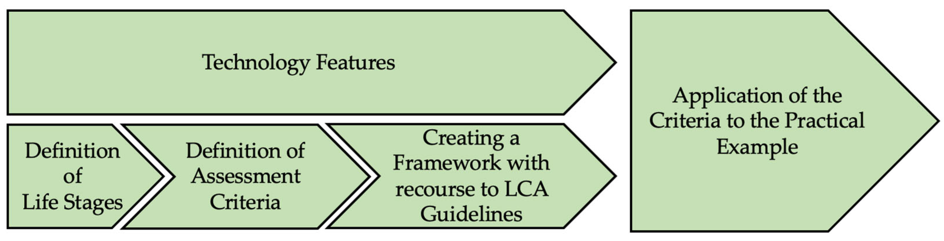
3. Systematic Approach to Assessing the Environmental Sustainability of Geothermal Heat Plants

Figure 1 gives an overview of the systematic approach described in this study. In order to be able to evaluate the environmental sustainability of deep geothermal heat plants, first, corresponding life stages have to be defined. The following section shows how and why a deep geothermal heat project can be divided into different life stages. Following this, suitable environmental sustainability assessment criteria must be defined. On this basis, the criteria can then be applied to a practical example. Concerning this last step, LCA guidelines form the foundation of the approach presented in the following sections. The systematic approach described in this study is based on the framework provided by DIN EN ISO 14040. Nevertheless, as explained in Section 1, the LCA guidelines serve only as a basis for the structure of our approach. Building on this, a novel methodology is developed in this study.

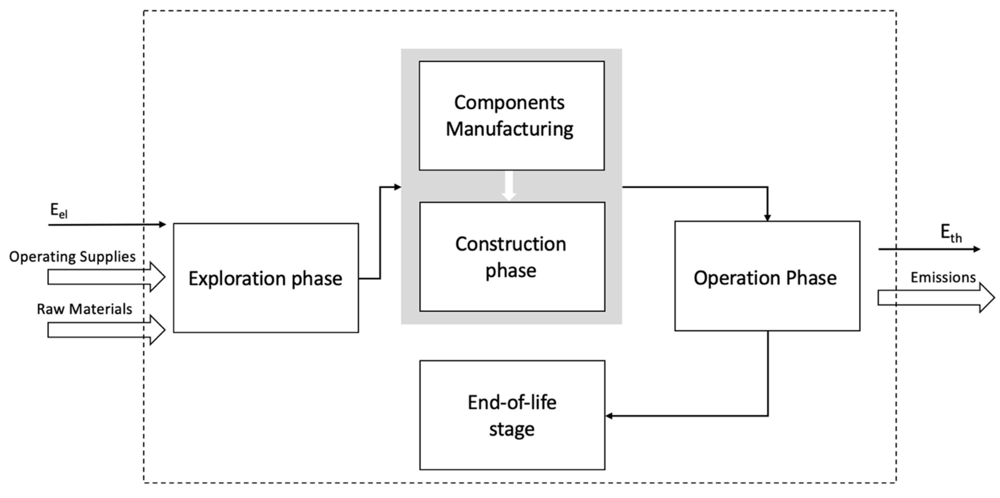
3.1. Definition of Life Stages

When looking at energy production plants or projects with a similar setup, environmental aspects beyond the operational phase, which often occurs with zero emissions, also need to be considered. With a focus on renewable energies, it is especially crucial to evaluate effects that precede or follow the operational phase [3]. As technologies vary widely, individual life stages should be defined for each technology or even for each individual project. There are several reasons for this: On the one hand, the subdivision of a project into several phases enables a more differentiated view. On the other hand, it makes it easier to trace environmental impacts arising from the plant back to their causes. At the same time, a detailed analysis allows one to point out improvement opportunities for the environmental compatibility of the plant.
When determining life stages, the degree of complexity of the technology and the desired level of detail must be taken into account. These aspects influence which process steps are relevant and which might be excluded. For geothermal projects, quite often, a subdivision into at least four life stages is suitable; for example, Marchand et al. [7] and Tosti et al. [11] used the following subdivision in their analyses: upstream processes, the construction phase, the operational phase, and the end-of-life stage.
With regard to an exemplary geothermal heat plant that is to be built in the Upper Rhine Valley, Germany, by 2025, the following life stages are defined:
  • “Exploration phase”: When planning the construction of a deep geothermal heat plant, the exploration of an area with geothermal potential takes place before the construction of the site.
  • “Construction phase”: More important is, however, the construction phase, as this is where most of the climate-impacting process steps occur.
  • “Operation phase”: Even though the operation of a geothermal power or heat plant is emission-free, the operation phase can be taken into consideration as well—for instance, by looking at the auxiliary energy used during operation.
  • “End-of-life stage”: Finally, aspects of the dismantling of a geothermal plant can be included in a sustainability assessment in the end-of-life stage [11].
These phases can be applied to any other deep geothermal heat plant. They are described in more detail in Section 3.3.2.

3.2. Definition of Assessment Criteria

The definition of suitable assessment criteria forms the basis for a sustainability evaluation. It can be useful to consider several different aspects to enable a multi-criteria—and, thus, extensive—assessment. Each deep geothermal system might have individual characteristics to be considered in the context of a sustainability assessment. Unlike many studies in the literature that follow LCA guidelines, our approach does not include an impact assessment with consideration of, for example, human health effects, a depletion of the ozone layer, or soil acidification as a result of the corresponding technology. Instead, the focus is on determining meaningful indicators that provide information about the efficiency and environmental compatibility of heat utilization from deep geothermal energy.
In contrast to the LCA procedure, which was used by numerous authors in the literature (see Section 2), our approach is based on different criteria. In order to assess the environmental sustainability of deep geothermal heat plants, according to expert evaluations, five quantitative assessment criteria were chosen, presented, and applied in this study after careful consideration and discussion:
  • The “space requirement” of the plant, including the area needed during both the construction phase and the operation phase.
  • The “energy consumption” over the life cycle of the plant, which can ultimately be related to the “energy returned on energy invested” (EROI) over its lifetime.
  • The “material consumption”, e.g., steel, cement, bentonite, and silica sand, used over the life cycle of a plant; this includes aspects of the deep well drilling and manufacturing of the components.
  • Resulting “CO2 emissions”, mainly considering the upstream chain, i.e., the production of materials and electricity.
  • The “water consumption” over the life cycle of the plant, mainly referring to the upstream chain of the manufacturing of the components.
For a better classification, following the ISO 14040 standard, the criteria can be related to 1 kWh of generated heat. This also lays the foundation for the comparability of the environmental compatibility of different plants and technologies [12]. CO2 emission factors and water consumption from the upstream chain can be taken from existing databases. In this study, mainly the database of the German Federal Environment Agency was used for calculations [13].

3.3. Creation of a Framework Based on LCA Guidelines

The impacts on the defined assessment criteria for geothermal heat plants need to be identified and quantified in each of the life stages determined above. Before doing so, according to the general approach of an environmental LCA according to the ISO 14040 and ISO 14044 standards, the goal of this study and its boundaries need to be defined. After the description of how the life stages and assessment criteria can be connected to the framework, the effects are evaluated and the results are interpreted [12,14].

3.3.1. Definition of the Goal, System Boundaries, and Limitations of this Study

The goals of sustainability assessments can be quite diverse. However, when placing the focus on aspects of environmental sustainability, as is intended in this study, it seems reasonable to interpret and use the data with regard to the scope for action to improve the environmental compatibility of the plant. Furthermore, a second goal is to use the calculated indicators for comparability with other technologies and plants [12].
Defining system boundaries requires a closer look at the life stages and potential interfaces with neighboring systems. The object of the analysis considered in this study is a deep geothermal system that has two deep wells and is exclusively used for heat generation. Figure 2 illustrates how system boundaries for deep geothermal heat plants can be determined. A division into the four life stages, as described in Section 3.1, seems reasonable. In this way, in addition to the construction and operation phases being the focus, the upstream and downstream process steps can be adequately considered as well. Concerning the temporal framework of the assessment, the technical lifetime of deep geothermal plants is usually assumed to be 30 years [4,6].
The definition of system boundaries is also key when aiming at comparing the results of a study with those of other projects. However, comparability is only given if the chosen research frameworks of the respective studies match [12]. In most LCA-based studies that focused on energy generation plants, 1 kWh was chosen as the functional unit [6,11,15]. Accordingly, 1 kWhth was defined here as the functional unit as well.
Regarding limitations, it is essential to weigh which aspects are relevant and which have a negligible impact on the environmental performance of the plant. Obviously, the more aspects are included, the more accurate an assessment will be. Nevertheless, for reasons of time and complexity, it can make sense to focus on only the most important aspects. In order to facilitate decision making if aspects are rather important or rather neglectable, it is advisable to initially obtain an overview of the magnitudes of the biggest environment-influencing process steps within the project. Other process steps can then be situated in relation to these. Concerning deep geothermal heat plants, the biggest influences are deep well drilling and the auxiliary energy used during operation. Starting from this point and with this relation, it is possible to estimate the influence of other process steps, such as the energy consumption during exploration, the material consumption of the components, and the transportation of materials. Moreover, it is important to mention that, finally, when calculating key metrics from the results of a life cycle inventory, some aspects are hardly significant when viewed as a whole. In this respect, it is evident that it is particularly important to accurately include the most influential factors in the analysis. Table 1 shows the aspects that were considered to be relevant in the context of the sustainability assessment in this study.

3.3.2. Identification and Quantification of Implications of Relevant Energy and Material Flows

This section deals with the identification of relevant energy and material flows over the life cycle and the stages of the product system defined in the previous section. First, and in order to illustrate how such a study of balance can be prepared for geothermal heat plants in general, the following section describes the process steps of the individual life stages of the planned geothermal heat plant that should be included in a sustainability assessment study and the extent to which they should be included. Then, in Section 4, the general process is applied to a real practical example. At this point, it should be mentioned that the values used were, for the most part, deliberately not taken from databases. A life cycle inventory is supposed to have high accuracy, and this needed to be specifically related to the planned geothermal heat plant in the Upper Rhine Valley, which will be presented in Section 4. Therefore, a large proportion of the values were manually balanced or requested from component manufacturers. A summary of the input data can be found in Table A1, Table A2, Table A3 and Table A4 in Appendix A.

Exploration Phase

The exploration phase includes, among other things, geophysical surveys. Of particular relevance in the context of an environmental sustainability assessment is the performance of a 3D seismic survey, which provides the essential basis for the selection of the site of a deep geothermal plant [16]. In this study, only the energy consumption of the seismic vibrators being used for the 3D seismic survey was assumed to have a notable impact on the environmental compatibility of the geothermal plant. This was due to the fact that other activities associated with 3D seismic surveys, such as permitting or the temporary use of land, have a negligible environmental impact with respect to the overall project.
In detail, the consumption of diesel fuel required by seismic vibration trucks and the resulting CO2 emissions and water consumption needed to be considered. The amount of diesel required for a seismic survey can be calculated by using the distance driven by the trucks plus the consumption during seismic vibrations according to Formulas (1) and (2). For the total amount, an additional 10% was foreseen for transposition maneuvers and unplanned routes; see Formula (3). The fuel consumption required for distances covered by passenger cars during permitted was considered to be negligible.
D i e s e l   c o n s u m p t i o n d r i v i n g l = t o t a l   d r i v i n g   d i s t a n c e   k m s p e c i f i c   c o n s u m p t i o n   l k m
D i e s e l   c o n s u m p t i o n v i b r a t i o n l = v i b r a t i o n   p o i n t s # v i b r a t i o n s   p e r   p o i n t # d u r a t i o n   p e r   v i b r a t i o n   s e c s p e c i f i c   c o n s u m p t i o n   l h   1 3600   h s e c
T o t a l   d i e s e l   c o n s u m p t i o n   l = 1.1 ( 1 + 2 )
Consultations with the truck producer revealed a specific consumption of 1 L/km for a 32-ton truck and 50 L/h for vibrations. By balancing the diesel fuel required by the trucks, the resulting CO2 emissions could be calculated. This was based on a specific calorific value of the diesel fuel of 41 MJ/kg and a density of 832 kg/m3 [17,18]. The weighted-average emission factors for diesel fuels related to summer and winter quality of 3.166 t CO2/t were used for the CO2 emissions occurring during the operation of the seismic vibrators [19]. It was also assumed that specific CO2 emissions of 7624 kg were assigned to 1 TJ of diesel in production [20]. Formulas (4) and (5) show the calculations. Formula (6) includes the values given above.
C O 2   e m i s s i o n s   f r o m   d i e s e l o p e r a t i o n t = t o t a l   d i e s e l   c o n s u m p t i o n   l d e n s i t y   o f   d i e s e l   k g m 3 1 1000 m 3 l 1 1000   t k g s p e c i f i c   C O 2   e m i s s i o n   f a c t o r   t   C O 2 t   d i e s e l
C O 2   e m i s s i o n s   f r o m   d i e s e l p r o d u c t i o n   t = t o t a l   d i e s e l   c o n s u m p t i o n   l d e n s i t y   o f   d i e s e l   k g m 3 1 1000 m 3 l 1 1000   t k g 1 1,000,000 T J M J c a l o r i c   v a l u e   M J k g s p e c i f i c   C O 2   e m i s s i o n   f a c t o r   k g   C O 2 T J   d i e s e l
T o t a l   C O 2   e m i s s i o n s   f r o m   d i e s e l   c o n s u m p t i o n   t = 0.00289 t l t o t a l   d i e s e l   c o n s u m p t i o n   [ l ]
Water consumption in the exploration phase is related to the production of diesel fuel. For every TJ of diesel fuel produced, 4607 kg of water must be used [20]. Thus, water consumption can be calculated according to Formula (7). See Table 2 at the end of the section on the end-of-life stage for a summary of the CO2 emission factors and specific water consumption of the materials considered in this study.
T o t a l   w a t e r   c o n s u m p t i o n   f r o m   d i e s e l   p r o d u c t i o n   l = t o t a l   d i e s e l   c o n s u m p t i o n   l d e n s i t y   o f   d i e s e l   k g m 3 1 1000 m 3 l 1 1,000,000 T J M J c a l o r i c   v a l u e   M J k g s p e c i f i c   w a t e r   f a c t o r   k g   w a t e r T J   d i e s e l
The aforementioned values for CO2 emissions and virtual water consumption were used in this study whenever diesel consumption was considered. The aspect of the space requirement can be excluded in the exploration phase since it is only a temporary use of an area. Then, following the same logic, the energy consumption can be calculated as follows:
E n e r g y   c o n s u m p t i o n   k W h = t o t a l   d i e s e l   c o n s u m p t i o n   l d e n s i t y   o f   d i e s e l   k g m 3 1 1000 m 3 l c a l o r i c   v a l u e   M J k g 1 3600 k W h k J 1000 k J M J

Construction Phase

When looking at the construction phase of a geothermal heat plant, multiple aspects must be taken into consideration. The construction phase can be divided into the drilling of the deep wells, the subsequent construction of the surface facility, and the connection of the plant to the district heating network. First of all, a restriction concerning transport routes can be made at this point. It is recommended to consider the extent to which the transportation of components or construction machinery plays a role in the overall picture. Transport routes are, therefore, only taken into account when they have a notable influence on the overall result.
Initially, a platform for the drilling rig must be poured. This is also connected with the asphalting of the drilling site. The area required by a geothermal system is at least 5000 m2 [21]. In this study, a geothermal plant that exclusively supplies heat is considered. Since geothermal heat plants do not require Organic Rankine Cycle (ORC) systems, it can be assumed that less land is required for them than for geothermal power plants. Therefore, the demand for concrete and asphalt can be estimated based on a direct surface of 5000 m2, which is split into 2200 m2 for concrete and 2800 m2 for asphalt. Expert interviews with civil engineers who worked on such plants in the past showed that an average thickness of 0.5 m could be assumed for the concrete, while for the asphalt, 0.14 m of ground asphalt and 0.04 m of surface asphalt should be sufficient. These data needed to be multiplied by the density values of 2.3 t/m3 for concrete, 2.45 t/m3 for ground asphalt, and 2.5 t/3 for surface asphalt. This resulted in the following material consumption:
c o n c r e t e   d r i l l i n g   s i t e   t = s u r f a c e   a r e a   m 2 a v e r a g e   t h i c k n e s s   m d e n s i t y   o f   c o n c r e t e t m 3
a s p h a l t   d r i l l i n g   s i t e   t = s u r f a c e   a r e a   m 2 ( a v e r a g e   t h i c k n e s s   o f   g r o u n d   a s p h a l t   m d e n s i t y   o f   g r o u n d   a s p h a l t   t m 3 + a v e r a g e   t h i c k n e s s   o f   s u r f a c e   a s p h a l t   m d e n s i t y   o f   s u r f a c e   a s p h a l t   t m 3 )
For the calculation of CO2 emissions, 0.161 kg CO2/kg concrete and 186.1 kg CO2/t asphalt could be used. With regard to virtual water consumption, values of 0.267 L water/kg concrete and 1413 L of water/t asphalt were assumed [22,23]. The formulas can be established via the multiplication of the factors by the results of Formulas (9) and (10). An example of the CO2 emissions of concrete is given in Formula (11).
C O 2   e m i s s i o n s   f r o m   c o n c r e t e   p r o d u c t i o n   t = c o n c r e t e   d r i l l i n g   s i t e   t s p e c i f i c   C O 2   e m i s s i o n s k g   C O 2 t   c o n c r e t e 1 1000 t k g
Furthermore, the consumption of diesel fuel by the construction machines and the corresponding CO2 emissions and water and energy consumption needed to be considered. The calculations followed the logic of Formulas (1)–(8). This included the transport of the drilling rig and of the drill pipes via trucks, which could easily exceed 100 truckloads and several hundreds of kilometers for every single delivery. The specific diesel consumption of a 40-ton truck was estimated to be 25 L/100 km. For each construction machine, the specific diesel consumption per hour and the total hours of operation needed to be derived in order to calculate the total diesel consumption according to Formula (2). Expert interviews revealed, for example, 15 L/h for a concrete mixer and 14 L/h for a compactor roll. Thus, for the area of 2200 m2 of concrete and 2800 m2 of asphalt from above, roughly 5600 L of diesel was required in total. The same approach could be used for the construction work for connecting the drilling site to the district heating grid. Here, 261 L of diesel per 100 m was calculated.
The establishment of the drilling site is followed by the drilling of a production well and an injection well. Depending on the region and the type of geothermal system, different drilling depths may be considered. In the Upper Rhine Valley—for example, in Insheim and Rittershoffen [11,24]—depths between 2500 m and over 3500 m are common. In this study, to stay on the conservative side, the deep wells were assumed to have a depth of 3500 m each. Regarding the deep-well-drilling process, an electric-powered drilling rig can be used to improve the carbon footprint compared to that of a diesel-powered drilling rig. It is important, however, to consider the type of electricity used with an electricity-powered drilling rig. When using electricity generated from renewable sources, CO2 emissions can be significantly reduced compared to those of using an electricity mix from renewable and fossil fuels. In this respect, the use of a drilling rig powered exclusively by green electricity appears to make sense from an environmental point of view. Due to the difficult predictability of the energy consumption of the drilling rig, which results from various aspects, it is possible to fall back on similar geothermal wells that have already been drilled. The electricity consumption for the drilling of two wells with a length of 3500 m each was calculated in this study to be about 1.2 GWh based on comparable projects. The corresponding CO2 emissions could be calculated depending on the prevailing electricity mix according to Formula (12). For instance, in Germany, in 2019, the CO2 emission factor for the electricity mix was 411 g CO2/kWh [25].
C O 2   e m i s s i o n s   f o r   w e l l   d r i l l i n g   e l e c t r i c t = e l e c t r i c i t y   c o n s u m p t i o n   k W h C O 2   e m i s s i o n   f a c t o r   f o r   t h e   e l e c t r i c i t y   m i x t   C O 2 k W h
The use of a drilling fluid during the drilling process must be considered. The fluid was assumed in this study to have a volume of about 7300 m3 based on comparable projects [26]. It could be presumed that the drilling fluid contained bentonite in an amount of 11% of the total volume [11]. In addition, the casing and cementing of the boreholes are also related to deep well drilling. Based on the results of Tosti et al. [11], this study assumed a material consumption of about 565 t of steel for the casing and about 539 t of cement, 217 t of silica sand, and 33.6 t of bentonite for the subsequent cementation. From this, the resulting CO2 emissions and water consumption emerging during the production of these materials could be calculated via multiplication by specific factors. For example, according to the database of the German Federal Environment Agency, the production of cement is assessed with a CO2 emission factor of 0.91 kg CO2/kg, bentonite is assessed with 24.7 kg CO2/t, and silica sand is assessed with 19.3 kg CO2/t. The following values were applied for virtual water consumption: 1.13 L of water/kg of cement, 69.8 L of water/t of bentonite, and 1466 L of water/t of silica sand [27,28,29].
After the drilling of the wells, the construction of the aboveground heat plant must be considered. When looking at geothermal heat plants, the surface building usually does not have to meet any special requirements and was, therefore, modeled as a common industrial building for the purposes of this study. Accordingly, the concrete and steel requirements for the construction of a single-story building with a floor area of about 240 m2 were considered here. The concrete and the steel could be calculated according to the thickness, widths, lengths, and heights of the walls and roof. The calculations of the related CO2 emissions and water consumption for concrete and steel production used the logic of Formulas (9) and (11) and the corresponding factors. For steel, 1.36 kg CO2/kg of steel and 11.7 L of water/kg of steel were applied [30]. Next, the components of the geothermal plant were analyzed according to the materials used, as well as their respective CO2 emissions and water and energy use. This included the feed pump and the injection pump, as well as the heat exchanger. In the Upper Rhine Valley, line-shaft pumps (LSPs) are usually used as feed pumps because they can generally withstand higher temperatures than electrical submersible pumps (ESPs) can. The selection of a feed pump is complex and depends on various factors, such as the temperatures and salinity of the thermal brine and the well depth. However, to be able to estimate the material requirements for an LSP, orientation toward comparable geothermal projects may be useful. At this point, the material consumption for the feed pump was estimated based on a pump with a power of 550 kW [31]. The LSP was mainly made of steel (especially the rods with a weight of about 40 t), but it also contained small amounts of aluminum (450 kg) and tin (180 kg). Following Tosti et al. [11], the LSP had an electric motor that was assumed to consist of equal parts steel and copper. Furthermore, an injection pump with an output of 110 kW was assumed in this study. The material requirements of the electric motor were taken into account with a steel and copper content of 50% each [11]. The choice of heat exchanger was also influenced by many factors. In geothermal plants, either tubular heat exchangers or plate heat exchangers are used. The necessary material expenses have to be designed individually depending on the volume flow rate, the temperatures, and other parameters, such as the pressure and the chemical composition of the geothermal brine [32]. In this study, a plate heat exchanger with a total weight of about 9 t was considered; it mainly consisted of stainless steel. The correct values can be derived from the dimensions of the heat exchanger according to the logic of Formula (9).
After the construction of the geothermal heat plant was fully considered, the connection to the district heating network could be included in the analysis—depending on how far apart the geothermal plant and the district heating network are. On the one hand, this involves the digging of a trench and the laying of the district heating pipeline. In most cases, buried plastic casing pipes are used, and their components are divided into steel for the carrier pipe and polyurethane and other plastics for the thermal insulation and casing [33]. For each kilometer, the need for roughly 44 t of steel, 6.7 t of polyethylene, and 4 t of polyurethane was identified. On the other hand, several district heating network pumps are required. The exact number depends on the water quantities in the district heating network, the control technology, and the redundancy requirements; thus, it must be individually determined. In this study, the number of district heating network pumps was determined on the basis of four single-stage volute casing pumps. Based on the output of the planned geothermal heat plant of 30 MWth, the output of one pump could be inferred. Accordingly, an electric motor with an output of 110 kW was selected for each pump, which is also assumed here to be made of 50% steel and 50% copper. The weights for the pumps and the motor can be obtained from the suppliers.
To calculate the CO2 emissions by using the logic of Formula (11), the specific CO2 emissions for the production of the materials were 1.36 kg CO2/kg steel, 1.64 kg CO2/kg copper, 9.42 kg CO2/kg aluminum, and 15,803 kg CO2/t tin [30,34,35,36]. Regarding the plastics (polyethylene and polyurethane) required for the district heating pipes, 2.42 kg CO2 and 4.2 kg CO2 resulted per kilogram produced, respectively [37,38].
The virtual water consumption for the production of the materials was 11.7 kg water/kg for steel, 4.01 kg water/kg for copper, 39.9 kg water/kg for aluminum, and 1,046,482 kg water/t for tin [30,34,35,36]. For the production of the plastics (polyethylene and polyurethane), 6.2 kg of water and 4.2 kg of water were required per kilogram in the production process, respectively [37,38].

Operation Phase

The operation of a geothermal heating plant is emission-free [3]. Nevertheless, some environmentally relevant aspects have to be considered in this phase as well. On the one hand, this applies to the regular replacement of the feed pump. In this study, according to our own assessment based on similar projects, a service life of the LSP of 7 years was assumed—i.e., in the course of the 30-year technical lifetime of the geothermal plant, a scheduled pump change will take place four times [31]. When replacing the feed pump, the aim is to achieve a high level of component reusability. Therefore, the material requirements for the pump itself were considered without replacing the rods. With regard to the resulting CO2 emissions and water consumption in the production of the materials for the pump, the same values and calculation procedures as those described in the section on the operation phase were applied. On the other hand, the auxiliary energy required for the feed pump and the circulation pumps of the district heating system influences the environmental performance of a geothermal system, since the purchase of electricity leads to CO2 emissions in the upstream chain. The power consumption of the LSP was calculated based on the pump capacity and the full load hours per year according to Formula (13).
T o t a l   p o w e r   c o n s u m p t i o n   k W h = p u m p   c a p a c i t y   k W f u l l   l o a d   h o u r s h y e a r o p e r a t i n g   t i m e y e a r s
When estimating the CO2 emissions resulting from the auxiliary energy for the feed pump and the circulating pumps of the district heating system, the forecasted development of the electricity mix in the country where the plant is located must be taken into account. The electricity mix in Germany, for example, is considered in relation to the period up to 2050, since all electricity in Germany is to come from renewable energies by 2050 [39]. Hence, the calculation assumed a linear decrease in specific CO2 emissions of the electricity mix in the period between 2025 and 2050.

End-of-Life Stage

The decommissioning of a geothermal plant after it has reached its maximum operating time (in this case, 30 years) essentially involves backfilling the deep wells in accordance with special mining authority specifications. This backfilling serves to prevent ground collapses and to permanently seal the boreholes against fluids. At the same time, it should remain possible to exploit mineral resources at a later date. Taking groundwater protection into account, the boreholes are partially backfilled by placing barriers at various heights [40]. Suitable materials for two 3500 m holes include approximately 33.5 t of cement, 1.5 t of bentonite, and 15.8 t of silica sand [41]. With regard to CO2 emissions and water consumption, the same values and calculations as those described in previous sections were applied.
The dismantling of the surface facility is also recommended not only from a legal point of view but also from the point of view of sustainability. According to the latter, it seems reasonable to strive for a high degree of reusability and recyclability of materials such as steel and concrete. Components that can still be used, e.g., heat exchangers or tubes, can be sold and reused at the end of the operating time of a plant. Similarly to a study by Parisi et al. [41], the disposal and recyclability of components was not considered in this study in more detail.

4. Application of the Approach to a Practical Example and Interpretation of the Results Obtained

In addition to the description of a systematic approach to assessing the environmental sustainability of deep geothermal heat plants, this study also aims to demonstrate its effectiveness by means of a practical example. For this reason, the model presented in this study was applied to a deep geothermal heat plant to be built in the Upper Rhine Valley, Germany, by 2025. It will be exclusively used for heat generation. The capacity of the plant was modeled to be 30 MWth for a lifetime of 30 years. A length of 1.5 km for the connection to the next district heating network was assumed. In Table 3, the results obtained by following the calculation approaches presented in Section 3 are shown.
The power consumption of the LSP was estimated based on a pump capacity of 550 kW and about 6000 full load hours per year. Based on these underlying assumptions, this led to a total energy consumption of the LSP in its 30-year technical lifetime of just over 100 GWh. Regarding the auxiliary energy required for the circulating pumps of the district heating system, an energy consumption of about 10 kWhel per 1 MWh of heat produced was assumed. Accordingly, this translated into another 50 GWh of energy demand over the 30-year life of the plant.
In the following, the obtained results and key metrics are analyzed and interpreted. They refer to the descriptions of the specific space requirement, EROI and energy payback time, specific CO2 emissions, and specific water consumption. A consideration of the material requirements does not appear to make sense in this context due to the wide range of material inputs.

4.1. Specific Space Requirement of the Plant

Assuming that the technical service life of the plant would be 30 years and that a heat quantity of about 5500 GWh would be produced, the area requirement of the geothermal plant during its operation could be related to the functional unit, i.e., to 1 kWh of heat produced. For the case considered here, this resulted in a specific space requirement of 0.9 mm2/kWhth. For comparison, solar heat requires a space of roughly 70,000 mm2/kWhth.

4.2. EROI and Energy Payback Time

The energy return on investment (EROI) is an important key metric when it comes to evaluating the relation between energy yield (ER) and energy consumption (EI) over the life cycle of a plant [42].
E R O I T = E R ( T ) E I ( T )  
The energy yield over the 30-year lifetime (T) of the plant was estimated to be about 5500 GWhth, while the energy invested added up to about 160 GWh. This resulted in an EROI value of approximately 34. Due to the lack of comparable data in the literature, EROIs of geothermal power plants could be used for plausibility. Atlason/Unnthorsson [43] evaluated various scenarios of a geothermal power plant with EROIs of just over 30. However, slightly higher values can be assumed for geothermal heat plants, since, for example, the coefficient of performance (COP) of geothermal heat generation is significantly higher than that for electricity generation. In addition, geothermal heat plants have a much lower self-consumption, since there is no ORC system that needs to be operated.
The so-called energy payback time can also be considered in this context. It shows the time after which a system is energetically amortized [42]. This value can be determined based on the lifetime of the plant and the EROI (see Formula (15)). The planned geothermal heat plant considered here is supposed to energetically amortize after about 315 days.
E n e r g y   P a y b a c k   T i m e = T E R O I

4.3. CO2 Emission Factor

In order to determine the specific CO2 emissions of the geothermal heat plant considered here, the total CO2 emissions caused over the entire life cycle of the plant were set in relation to the total energy yield. This meant that a reference to the functional unit—defined here with 1 kWhth—was established. With total CO2 emissions of about 30,867 t and a total energy yield of about 5500 GWhth, a CO2 emission factor of 5.56 g CO2/kWhth could be identified for the planned geothermal heat plant. However, there were several underlying assumptions. The stated value refers to the use of an electricity mix of renewable and fossil energies during both the drilling phase and the operation of the plant. If, however, only renewably generated electricity would be used in both cases, the specific CO2 emissions could be reduced to about 0.05 g CO2/kWhth. To check the plausibility of these values, a study by the Federal Environment Agency in which the CO2 emissions avoided by various renewable energy sources were balanced in Germany for the year 2020 was used. A geothermal heat plant with 3000 full load hours per year and a capacity of approximately 9 MWth served as the basis here. Here, a CO2 emission factor of just under 30 g CO2/kWhth was specified accordingly, with approximately 6 g CO2/kWhth falling on the upstream chain and approximately 24 g CO2/kWhth on auxiliary energy during operation [3]. In view of the almost threefold higher output for the project considered here, as well as the use of twice the number of full load hours, the significantly lower CO2 emission factor of the geothermal plant considered in this work can be explained. For comparison, in 2020, the specific CO2 emissions of the district heating mix in Mannheim, Germany, were about 173 g CO2/kWhth [44].

4.4. Water Consumption

The total water consumption can also be related to the functional unit. Thus, a value of 0.0028 L/kWhth (≙2.8 L/MWhth) was obtained. However, due to the lack of well-founded comparative values, no reference to other heat generation technologies can be made at this point.

4.5. Discussion

By means of a practical example, this study showed the circumstances under which deep geothermal heat plants can be operated in a particularly sustainable manner and which aspects in the individual life stages of such a plant have the greatest influence on its environmental compatibility. The key results are summarized in Table 4. There are two particular aspects that have a significant impact on the environmental compatibility of a plant. On the one hand, this is the energy required for drilling, which can be made almost CO2-neutral by using electricity generated from renewable sources. On the other hand, the electricity demand of the feed pump and the district heating network pumps during operation is responsible for CO2 emissions generated in the upstream chain. This is where the greatest scope for action in order to improve the environmental sustainability of a deep geothermal heat plant lies.
It can be concluded from this that other aspects, such as transport routes, maintenance, and the deconstruction of the plant at the end of its service life, are of little significance. This is because they are several orders of magnitude smaller than the values calculated in this article for the aspects presented here. They can, therefore, be assumed to be negligible in sustainability analyses of deep geothermal heat plants. Table 5 summarizes the key metrics that were determined in relation to the exemplary deep geothermal heat plant.

5. Summary and Conclusions

Heat from deep geothermal energy will play an increasingly important role in the renewable energy supply. In order to fill the existing research gap in the literature regarding the sustainability of geothermal heat plants, this study described a systematic approach that enables one to determine relevant sustainability indicators of individual deep geothermal systems used for heat generation. This approach involves first defining appropriate life stages of a geothermal system. After choosing meaningful evaluation criteria, these can be applied to the individual life stages of the plant to finally obtain sustainability indicators.
Summing up the relevant energy and material flows, the exemplary geothermal heat plant used as a reference for the application in this study causes specific CO2 emissions of only 0.05 g/kWhth in the best case. Due to the high COP of geothermal heat generation, an EROI of about 34 can be achieved, which is also in the sense of environmental sustainability. Accordingly, if a sustainability analysis of this kind is carried out even before the start of the project, measures that improve the environmental balance of the plant can already be defined in the planning phase.
Even if economic and social criteria have not yet been considered in this study, this can be performed in subsequent studies—for example, in the form of a life-cycle cost analysis or a social life-cycle assessment. In this way, those aspects that concern large investments, especially at the beginning of a deep geothermal project, can be adequately assessed. An analysis of the social acceptance of geothermal energy may also be essential. The skepticism of many citizens due to seismic events in connection with some geothermal plants seems to be high, despite the scientific facts that confirm the advantages and low risk of the technology. Thus, it seems reasonable to focus not only on scientific facts but also on creating transparency and trust among the population in order to increase the social acceptance of geothermal energy.

Author Contributions

Conceptualization, L.M. and S.S.; methodology, L.M.; validation, L.M.; formal analysis, L.M.; investigation, L.M.; resources, L.M.; data curation, L.M.; writing—original draft preparation, L.M.; writing—review and editing, L.M. and S.S.; visualization, L.M.; supervision, S.S.; project administration, L.M. All authors have read and agreed to the published version of the manuscript.

Funding

This research received no external funding.

Data Availability Statement

The data presented in this study are available on request from the corresponding author. The data are not publicly available due to confidentiality reasons related to the respective companies.

Acknowledgments

L.M. and S.S. acknowledge the MVV Umwelt GmbH, Mannheim, Germany, for providing this topic and for their support in data acquisition.

Conflicts of Interest

The authors declare no conflict of interest.

Appendix A

To provide a clearer understanding of the input data required to conduct the analysis, Table A1, Table A2, Table A3 and Table A4 present a comprehensive summary of the data along with their corresponding references.
Table A1. Summary of the input data and their references during the exploration phase.
CategoryInput DataReference
Diesel consumption of a vibration truck while driving1 L/kmExpert interview with the truck producer
Diesel consumption of a vibration truck while vibrating50 L/hExpert interview with the truck producer
Route of vibration trucks250 kmSeismic survey study provided by a service provider
Table A2. Summary of input data and their references during the construction phase.
CategoryInput DataReference
Surface of the drilling site5000 m2Expert interview with a civil engineer
thereof surface of concrete2200 m2
thereof surface of asphalt2800 m2
Thickness of concrete0.5 m
Thickness of asphalt0.04 m
Diesel consumption of a 40-ton truck25 L/100 kmExpert interview with a civil engineer
Diesel consumption of a concrete mixer (drilling site)15 L/hExpert interview with a civil engineer
Diesel consumption of a compactor roll (drilling site)14 L/h
Diesel consumption of a wheel loader (trench for district heating grid)9.5 L/hExpert interview with a civil engineer
Diesel consumption of a compactor
(trench for district heating grid)
5.5 L/h
Depth of each deep well3500 mAuthors’ own estimate based on local geophysical data and comparable projects in the
Upper Rhine Valley
Electricity consumption (drilling of the two deep wells)1.2 GWhExpert interview with a drilling service provider
Volume of drilling fluid7300 m3[26]
Material consumption of casing [11]
thereof steel565 t
thereof cement539 t
thereof silica sand217 t
thereof bentonite33.6 t
Floor area of aboveground heat plant240 m2Expert interview with a plant operator
Power of an LSP550 kW[30]
Material consumption of an LSP Expert interview with a pump manufacturer
thereof steel40 t
thereof aluminum450 kg
thereof tin180 kg
Material consumption of the electric motor of an LSP Ref. [11]; Expert interview with a pump manufacturer
thereof steel1.25 t
thereof copper1.25 t
Material consumption of an injection pump
thereof steel
1.2 tExpert interview with a pump manufacturer
Material consumption of a heat exchangerthereof steel9 tExpert interview with a heat exchanger manufacturer
Material consumption of a district heating pipeline Expert interview with a pump manufacturer
thereof steel44 t/km
thereof polyethylene6.7 t/km
thereof polyurethane4 t/km
Material consumption of four district heating network pumps + motors (power of motor: 110 kW) Service datasheet of a pump manufacturer
thereof steel5.67 t
thereof copper2.19 t
Distance between the heat plant and district heating network1.5 kmAuthors’ own estimate based on local geographic conditions
Table A3. Summary of input data and their references during the operation phase.
CategoryInput DataReference
Lifetime of the LSP7 yearsAuthors’ own estimate based on comparable projects; [30]
Material consumption for the replacement of the LSP Authors’ own calculations
thereof steel22 t
thereof aluminum1800 kg
thereof copper1080 kg
thereof tin720 kg
Table A4. Summary of input data and their references during the end-of-life stage.
CategoryInput DataReference
Material consumption for the backfilling of the deep wells [41]
thereof cement33.5 t
thereof bentonite1.5 t
thereof silica sand15.8 t

References

  1. Risquez, M.A.; Grassi, G.; Solazzo, E.; Jacome, F.O.D.; Guizzardi, D.; Rossi, S.; San-Miguel-Ayanz, J.; Pagani, F.; Crippa, M.; Olivier, J.; et al. Emissions Database for Global Atmospheric Research; Version v7.0_FT_2021; European Commission, Joint Research Centre (JRC): Brussels, Belgium, 2022; Available online: http://data.europa.eu/89h/e0344cc3-e553-4dd4-ac4c-f569c8859e19 (accessed on 5 February 2023).
  2. IRENA. Renewable Capacity Statistics 2022; IRENA: Abu Dhabi, United Arab Emirates, 2022; Available online: https://www.irena.org/-/media/Files/IRENA/Agency/Publication/2022/Apr/IRENA_RE_Capacity_Statistics_2022.pdf (accessed on 29 August 2022).
  3. Lauf, T.; Memmler, M.; Schneider, S. Emissionsbilanz Erneuerbarer Energieträger 2020—Bestimmung der Vermiedenen Emissionen Im Jahr 2020; Umweltbundesamt: Dessau-Roßlau, Germany, 2021; Available online: https://www.umweltbundesamt.de/sites/default/files/medien/1410/publikationen/2021-12-13_climate-change_71-2021_emissionsbilanz_erneuerbarer_energien_2020_bf_korr-01-2022.pdf (accessed on 6 February 2023).
  4. Agemar, T.; Suchi, E.; Moeck, I. Die Rolle der Tiefen Geothermie Bei der Wärmewende—Wie Deutschland 60% Erneuerbare Wärme bis 2050 Schaffen Könnte; Positionspapier; Leibniz-Institut für Angewandte Geophysik: Hannover, Germany, 2018; Available online: https://www.leibniz-liag.de/fileadmin/user_upload/s4/downloads/positionspapier_waermewende.pdf (accessed on 15 October 2022).
  5. Ortner, S.; Mellwig, P.; Blömer, S.; Rettenmaier, N.; Pehnt, M.; Möhring, P.; Sandrock, M.; Akram, P. Berichtspflicht Gemäß der Richtlinie (EU) 2018/2001 Zum Potenzial der Nutzung von Energie Aus Erneuerbaren Quellen. Bewertung des Potenzials im Bereich der Energie Aus Erneuerbaren Quellen und Der Nutzung von Abwärme und -kälte im Wärme- und Kältesektor in der Bundesrepublik Deutschland; Ifeu—Institut für Energie- und Umweltforschung Heidelberg gGmbH: Heidelberg, Germany; Hamburg Institut Research gGmbH: Hamburg, Germany, 2020; Available online: https://ec.europa.eu/energy/sites/default/files/de_ca_2020_de_a01_art_157_red_ii_report_germany.pdf (accessed on 14 June 2022).
  6. Parisi, M.L.; Basosi, R. Geothermal Energy Production in Italy: An LCA Approach for Environmental Performance Optimization. In Life Cycle Assessment of Energy Systems and Sustainable Energy Technologies: The Italian Experience; Basosi, R., Cellura, M., Longo, S., Parisi, M.L., Eds.; Springer International Publishing: Cham, Switzerland, 2019; pp. 31–44. [Google Scholar]
  7. Marchand, M.; Blanc, I.; Marquand, A.; Beylot, A.; Bezelgues-Courtade, S.; Traineau, H. Life Cycle Assessment of High Temperature Geothermal Energy Systems; O.I.E.—Centre for Observation, Impacts, Energy: Melbourne, Australia, 2015; Available online: https://hal-mines-paristech.archives-ouvertes.fr/hal-01146355/document (accessed on 29 January 2023).
  8. Douziech, M.; Ravier, G.; Ferrara, N.; Damen, L.; Sigurjonsson, H.A.; Pérez-López, P.; Tosti, L.; Gudjonsdottir, S.; Harcouet-Menou, V.; Parisi, M.; et al. Simplified Parameterized Models for a Multi-Criteria Environmental Impact Assessment of Four Types of Geothermal Installations. In Proceedings of the World Geothermal Congress 2020 + 1, Reykjavik, Iceland, 24–27 October 2021; Available online: https://hal-mines-paristech.archives-ouvertes.fr/hal-03616551/document (accessed on 15 June 2023).
  9. Colucci, V.; Manfrida, G.; Mendecka, B.; Talluri, L.; Zuffi, C. LCA and Exergo-Environmental Evaluation of a Combined Heat and Power Double-Flash Geothermal Power Plant. Sustainability 2021, 13, 1935. [Google Scholar] [CrossRef]
  10. GEOENVI. About the Project; GEOENVI: Florianópolis, Brasil, 2019; Available online: https://www.geoenvi.eu/about-us/ (accessed on 29 July 2022).
  11. Tosti, L.; Ferrara, N.; Blanc, I.; Douziech, M.; Fiaschi, D.; Manfrida, G.; Mendecka, B.; Parisi, M.L.; Pérez-López, P.; Ravier, G. Environmental Assessment of GEOENVI Case Studies: A Selection of GEOENVI Case Studies Following the Harmonized LCA Guidelines: GEOENVI, n.p. 2020. Available online: https://www.geoenvi.eu/wp-content/uploads/2020/11/D3.3-Environmental-assessment-of-GEOENVI-case-studies.pdf (accessed on 5 July 2022).
  12. DIN EN ISO 14040:2006 + A1:2020; Umweltmanagement—Ökobilanz—Grundsätze und Rahmenbedingungen. International Organization for Standardization: Geneva, Switzerland, 2021.
  13. ProBas. ProBas—Willkommen bei ProBas! 2022. Available online: https://www.probas.umweltbundesamt.de/php/index.php (accessed on 6 February 2023).
  14. DIN EN ISO 14044:2006 + A1:2018 + A2:2020; Umweltmanagement—Ökobilanz—Anforderungen und Anleitungen. International Organization for Standardization: Geneva, Switzerland, 2021.
  15. Frick, S.; Kaltschmitt, M.; Schröder, G. Life cycle assessment of geothermal binary power plants using enhanced low-temperature reservoirs. Energy 2010, 35, 2281–2294. [Google Scholar] [CrossRef]
  16. Stober, I.; Bucher, K. Geothermal Energy; Springer: Berlin/Heidelberg, Germany, 2013. [Google Scholar]
  17. Kuchling, H. Taschenbuch der Physik: Mit Tabellen; Hanser: München, Germany, 2011. [Google Scholar]
  18. Amtsblatt der Europäischen Kommission. DURCHFÜHRUNGSVERORDNUNG (EU) 2022/996 DER KOMMISSION vom 14. Juni 2022 über Vorschriften für die Überprüfung in Bezug auf die Nachhaltigkeitskriterien und die Kriterien für Treibhausgaseinsparungen Sowie die Kriterien für ein Geringes Risiko Indirekter Landnutzungsänderungen. 2022. Available online: https://eur-lex.europa.eu/legal-content/DE/TXT/PDF/?uri=CELEX:32022R0996&from=EN (accessed on 15 July 2022).
  19. ProBas. ProBas—Prozessdetails: RaffinerieÖl-Produkte-EU-2020. 2020. Available online: https://www.probas.umweltbundesamt.de/php/prozessdetails.php?id=%7bCD742530-52AB-4F73-8291-978FA3233904%7d (accessed on 5 January 2023).
  20. Umweltbundesamt. CO2-Emissionsfaktoren Für Fossile Brennstoffe; Umweltbundesamt: Dessau-Roßlau, Germany, 2022; Available online: https://www.umweltbundesamt.de/sites/default/files/medien/479/publikationen/cc_28-2022_emissionsfaktoren-brennstoffe_bf.pdf (accessed on 8 July 2022).
  21. Watson, A. Geothermal Engineering; Springer: New York, NY, USA, 2013. [Google Scholar]
  22. ProBas. ProBas—Prozessdetails: Steine-ErdenBeton-DE-2020. 2020. Available online: https://www.probas.umweltbundesamt.de/php/prozessdetails.php?id={4E639AF4-5C74-4E19-92DB-2C2362779C93} (accessed on 5 January 2023).
  23. ProBas. ProBas—Prozessdetails: Asphalt. 2000. Available online: https://www.probas.umweltbundesamt.de/php/prozessdetails.php?id={3928FE68-D230-4711-9F6D-EFD800E73A4C} (accessed on 5 January 2023).
  24. NatürLich Insheim GmbH. Unser Projektvorhaben Natür3Lich Insheim. 2022. Available online: https://natuerlich-insheim.eu/ (accessed on 27 November 2022).
  25. Icha, P.; Lauf, T. Entwicklung der Spezifischen Treibhausgas-Emissionen des Deutschen Strommix in den Jahren 1990–2021; Umweltbundesamt, Dessau-Roßlau Herausgeber: Dessau-Roßlau, Germany, 2022; Available online: https://www.umweltbundesamt.de/sites/default/files/medien/1410/publikationen/2022-04-13_cc_15-2022_strommix_2022_fin_bf.pdf (accessed on 2 April 2023).
  26. Pratiwi, A.; Ravier, G.; Genter, A. Life-Cycle Climate-Change Impact Assessment of Enhanced Geothermal System Plants in the Upper Rhine Valley. Geothermics 2018, 75, 26–39. [Google Scholar] [CrossRef]
  27. ProBas. ProBas—Prozessdetails: Steine-ErdenZement-DE-2020. 2020. Available online: https://www.probas.umweltbundesamt.de/php/prozessdetails.php?id={25EB12F5-7A9B-425D-AC38-AAFE68C10831} (accessed on 5 January 2023).
  28. ProBas. ProBas—Prozessdetails: Bentonit. 1999. Available online: https://www.probas.umweltbundesamt.de/php/prozessdetails.php?id={8134CC95-DA9F-4670-BB70-BB2A0A04C6E4} (accessed on 5 January 2023).
  29. ProBas. ProBas—Prozessdetails: Quarzsand. 2000. Available online: https://www.probas.umweltbundesamt.de/php/prozessdetails.php?id={DE74DB83-30E7-4846-B6AE-8321A4273634} (accessed on 5 January 2023).
  30. Hettkamp, T.; Baumgärtner, J.; Paredes, R.; Ravier, G.; Seibel, O. Industrial Experiences with Downhole Geothermal Line-Shaft Production Pumps in Hostile Environment in the Upper Rhine Valley. In Proceedings of the World Geothermal Congress 2020, Reykjavik, Iceland, 26 April–2 May 2020; Available online: https://docplayer.net/181155892-Industrial-experiences-with-downhole-geothermal-line-shaft-production-pumps-in-hostile-environment-in-the-upper-rhine-valley.html (accessed on 4 September 2022).
  31. Gec-co Global Engineering & Consulting-Company GmbH. Vorbereitung und Begleitung Bei der Erstellung Eines Erfahrungsberichts Gemäß § 97 Erneuerbare-Energien-Gesetz—Teilvorhaben II b; Final Scientific Report; Geothermie: Augsburg, Germany, 2019; Available online: https://www.erneuerbare-energien.de/EE/Redaktion/DE/Downloads/bmwi_de/gec-co-vorbereitung-begleitung-eeg.pdf?__blob=publicationFile&v=7 (accessed on 27 January 2023).
  32. Konstantin, P.; Konstantin, M. Praxisbuch der Fernwärme- und Fernkälteversorgung; Systeme, Netzaufbauvarianten, Kraft-Wärme- und Kraft-Wärme-Kälte-Kopplung, Kostenstrukturen und Preisbildung; Springer: Berlin/Heidelberg, Germany, 2022. [Google Scholar]
  33. ProBas. ProBas—Prozessdetails: MetallStahl-mix-DE-2020. 2020. Available online: https://www.probas.umweltbundesamt.de/php/prozessdetails.php?id={00D85136-E496-4DE0-929B-10CB6A19DA02} (accessed on 5 January 2023).
  34. ProBas. ProBas—Prozessdetails: MetallKupfer-DE-sekundär-2020. 2020. Available online: https://www.probas.umweltbundesamt.de/php/prozessdetails.php?id={10BA69B7-53A2-4384-B5E3-BA9053623CE4} (accessed on 5 January 2023).
  35. ProBas. ProBas—Prozessdetails: MetallAluminium-DE-2020. 2020. Available online: https://www.probas.umweltbundesamt.de/php/prozessdetails.php?id={DD29CB08-8E9B-4E7A-A5F8-B74E631F2290} (accessed on 5 January 2023).
  36. ProBas. ProBas—Prozessdetails: Zinn. 2000. Available online: https://www.probas.umweltbundesamt.de/php/prozessdetails.php?id={6657A539-8BED-48E2-BE3A-FC2B46127395} (accessed on 5 January 2023).
  37. ProBas. ProBas—Prozessdetails: Chem-OrgLDPE-DE-2020. 2020. Available online: https://www.probas.umweltbundesamt.de/php/prozessdetails.php?id={48CFC911-59BE-4B9A-B1B0-41FE2AA152A8} (accessed on 5 January 2023).
  38. ProBas. ProBas—Prozessdetails: KunststoffPUR-Hartschaum-DE-2020. 2020. Available online: https://www.probas.umweltbundesamt.de/php/prozessdetails.php?id={7D803D25-E3D0-406C-8A4E-C883F6FEB851} (accessed on 5 January 2023).
  39. Bundesministerium für Umwelt, Naturschutz und nukleare Sicherheit (BMU). Klimaschutz in Zahlen—Fakten, Trends und Impulse Deutscher Klimapolitik, Ausgabe. 2021. Available online: https://www.bmuv.de/fileadmin/Daten_BMU/Pools/Broschueren/klimaschutz_zahlen_2021_bf.pdf (accessed on 15 July 2022).
  40. Clausthal-Zellerfeld, O. Richtlinie des Oberbergamtes in Clausthal-Zellerfeld über das Verfüllen auflässiger Bohrungen. 1998. Available online: https://bergpass.lbeg.de/media/204 (accessed on 16 July 2022).
  41. Parisi, M.L.; Douziech, M.; Tosti, L.; Pérez-López, P.; Mendecka, B.; Ulgiati, S.; Fiaschi, D.; Manfrida, G.; Blanc, I. Definition of LCA Guidelines in the Geothermal Sector to Enhance Result Comparability. Energies 2020, 13, 3534. [Google Scholar] [CrossRef]
  42. Joos, F. Nachhaltige Energieversorgung: Hemmnisse, Möglichkeiten und Einschränkungen; Eine Interdisziplinäre Statusbetrachtung: Wiesbaden, Germany, 2019. [Google Scholar]
  43. Atlason, R.S.; Unnthorsson, R. Hot Water Production Improves the Energy Return on Investment of Geothermal Power Plants. Energy 2013, 51, 273–280. [Google Scholar] [CrossRef]
  44. Technische Universität Dresden. Zertifikat. 2020. Available online: https://www.mvv-netze.de/fileadmin/user_upload_mvv-netze/Dokumente/partner/installateure/Zertifikate_PEF_CO2_2020.pdf (accessed on 6 February 2023).
Figure 1. Structure of the systematic approach.
Energies 16 06774 g001
Figure 2. System boundaries for the life cycle of a deep geothermal heat plant.
Energies 16 06774 g002
Table 1. Relevant criteria in each of the life stages considered in this study.
Criterion/Life StageExploration
Phase
Construction
Phase
Operation
Phase
End-of-Life
Stage
Space requirement XX
Energy consumptionXXXX
Material consumption XXX
CO2 emissionsXXXX
Water consumptionXXXX
Table 2. CO2 emission factors and specific water consumption for relevant materials.
MaterialCO2 Emission FactorSpecific Water
Consumption
Diesel fuel (driving)3.166 t CO2/t-
Diesel fuel (production)7.624 t CO2/TJ4607 kg water/TJ
Concrete0.161 kg CO2/kg0.267 kg water/kg
Asphalt186.1 kg CO2/kg1.413 kg water/kg
Cement0.91 kg CO2/kg1.13 kg water/kg
Bentonite0.0247 kg CO2/kg0.0698 kg water/kg
Silica sand0.0193 kg CO2/kg1.466 kg water/kg
Steel1.36 kg CO2/kg11.7 kg water/kg
Copper1.64 kg CO2/kg4.01 kg water/kg
Aluminum9.42 kg CO2/kg39.9 kg water/kg
Tin15.803 kg CO2/kg1046.482 kg water/kg
Polyethylene2.42 kg CO2/kg6.2 kg water/kg
Polyurethane4.2 kg CO2/kg4.2 kg water/kg
Table 3. Results of the practical example.
Criterion/Life StageExploration PhaseConstruction
Phase
Operation
Phase
End-of-Life
Stage
Space requirement 15,000 m25000 m2
Energy consumption497 MWh1858 MWh157,223 MWh388 MWh
Material consumption concrete: 3365 t
asphalt: 1240 t
bentonite: 2134 t
steel: 685 t
silica sand: 217 t
aluminum: 0.45 t
copper: 16 t
tin: 0.18 t
stainless steel: 6.8 t
polyethylene: 10 t
polyurethane: 6 t
steel: 27 t
aluminum: 1.8 t
copper: 11.9 t
tin: 0.7 t
concrete: 34 t
bentonite: 1.5 t
sand: 16 t
CO2 emissions151.8 t2807 t 1 or
2343 t 2
27,759 t 3 or
90 t 4
149 t
Water consumption8.24 m314,424 m31133 m363 m3
1 Use of an electrically driven drilling rig and a mix of fossil and renewable energy sources. 2 Use of an electrically driven drilling rig and renewable energy sources only. 3 Use of an electricity mix of fossil and renewable energy sources. 4 Use of 100% renewable energy sources.
Table 4. Summary of the resource consumption and resulting CO2 emissions.
CriterionValue
Energy consumption159,965 MWh
Max. CO2 emissions30,867 t
Water consumption15,628 m3
Table 5. Summary of key metrics of the sustainability of the considered deep geothermal heat plant.
Sustainability IndicatorValue
Energy returned on energy invested (EROI)
Energy payback time
~34
~315 days
CO2 emission factor~5.56 g/kWhth resp. ~0.05 g/kWhth
Water consumption~0.0028 L/kWhth (≙2.8 L/MWhth)
Disclaimer/Publisher’s Note: The statements, opinions and data contained in all publications are solely those of the individual author(s) and contributor(s) and not of MDPI and/or the editor(s). MDPI and/or the editor(s) disclaim responsibility for any injury to people or property resulting from any ideas, methods, instructions or products referred to in the content.

