Article

Enhancing the Power Performance of Latent Heat Thermal Energy Storage Systems: The Adoption of Passive, Fractal Supports

1
High Performance Computing Department, CINECA Rome Section, 00185 Rome, Italy
2
Italian Institute of Technology, Center for Life Nano- and Neuro-Science, 00161 Rome, Italy
3
Department of Physics, Harvard University, Cambridge, MA 02138, USA
4
Department of Enterprise Engineering “Mario Lucertini”, University of Rome “Tor Vergata”, 00133 Rome, Italy
*
Author to whom correspondence should be addressed.
Energies 2023, 16(19), 6764; https://doi.org/10.3390/en16196764
Submission received: 31 July 2023 / Revised: 5 September 2023 / Accepted: 19 September 2023 / Published: 22 September 2023
(This article belongs to the Special Issue Nanofluids Heat Transfer II)

Abstract

:
We employ a three-phase thermal lattice Boltzmann model (LBM) to investigate the power performance of latent heat thermal energy storage (LHTES) systems based on the exploitation of phase change materials (PCMs). Different passive thermal supports are considered to increase the melting rate, including innovative, fractal, branch-like structures. Our simulations reveal that the adoption of fractal, branch-like metal supports consistently outperforms other configurations in terms of PCM melting rates. These results open the path towards novel strategies to enhance the power performance of PCM-based TES systems, offering potential benefits for energy storage applications.

1. Introduction

Thermal energy storage (TES) systems are the object of extensive research efforts, in recent years, as promising contributors to increasing the sustainability of heating and cooling [1]. In the EU, in fact, domestic heating and hot water production account for almost 80% of total energy use [1], while worldwide heat contributes to 40% of total CO 2 emissions [2].
TES systems based on phase change materials (PCMs), also known as latent heat TES (LHTES), can store large amounts of waste heat at almost constant temperature, providing an ideal solution for technical applications that require thermal baths [3,4,5], including hydrogen storage via metal hydrides [6,7]. The drawbacks of LHTES systems are typically related to (i) incongruent melting/phase separation, (ii) subcooling, and (iii) low thermal conductivity, delivering limited heat transfer rates and poor power performance [8,9]. To increase the thermal conductivity of the PCM matrix, several strategies are explored in the literature that can essentially be grouped in the following categories [9]:
  • Realization of optimized blends of PCMs: blends can be formulated in the attempt to get the desired PCM thermal properties to better suit the designed application [10];
  • Adoption of highly conductive thermal supports: realized in the forms of fins, blades, heat pipes, and foams [11]. Their exploitation strongly enhances thermal conductivity (>200×, when embedding the PCM in porous graphite [12,13]), but can lead to detachment phenomena between the PCM and the thermal support. This phenomenon is due to the volumetric variation during melting/solidification and causes poor performance in repeated cycles [14];
  • Addition of micro-/nano-particles: the adoption of micro/nano-particles, nano-fibers, nano-tubes, and other nano-scale fillers can actually provide remarkable enhancements in specific heat, thermal conductivity, and thermal diffusivity (pristine graphene allows an increase in thermal conductivity up to 2800 % [15,16]);
  • Encapsulation: an expensive procedure that can even turn into the opposite result, increasing the overall thermal resistance, through the insertion of the coating layer [9]; moreover, the stability of the coating for repeated melting/solidification in time is still an open issue [17].
This study aims at investigating the enhancement of power performance of TES systems by utilizing solid thermal supports to increase the melting rate of phase change materials. More specifically, we study the melting rate performance of PCMs at low to intermediate Rayleigh numbers, 0 < Ra < 10 6 , through an ad hoc designed numerical platform based on the lattice Boltzmann method (LBM) [18,19]. The proposed approach capitalizes on the model developed in [20] and extended in [7]. LBM has proven flexible and reliable in simulating different complex systems at the intersection between engineering, physics, and biology [21,22,23,24,25,26,27], thus providing an efficient and computationally light alternative to Navier–Stokes-based computational frameworks. Recently, LBM has been also applied to conjugate heat transfer problems, delivering interesting and reliable predictions [20,28,29,30,31].
To evaluate the impact of the morphology of the thermal support, we conduct our simulations considering different layouts of thermal solid supports. The adoption of such supports is known from the literature as one of the strategies to improve the typical drawback of PCM systems, namely their reduced thermal conductivity [9]. However, no final solutions have been found in the literature to date, with several authors proposing their own layout, in the form of thin blades, thicker fins, porous structures, and even graphitized networks [32]. Fins and blades represent the simplest structures for thermal conductivity enhancement. They do not suffer from filling problems, such as the porous structures, and allow the onset of convective motions [33]. However, the adoption of fins and blades can lead to PCM detachments during repeated melting and solidification processes [14]. Fractal structures represent a novelty in the panorama of thermal supports [34]. Such solutions prove capable of decreasing the PCM thermal lag and increasing the PCM solidification rate during the heat-discharge process, thanks to their high surface-to-volume ratio compared to more conventional designs [34].
Here, we further develop the concept of fractal thermal supports by introducing novel branch-like structures that can benefit from the recent developments of 3D-printing technology. The branched layout allows for high surface-to-volume ratios, provides efficient heat transport high mass transfer capability, due to its bifurcations, and allows for the onset of convective motions [33,35], opening the path towards the design and implementation of future, highly efficient thermal energy storage systems.

2. Materials and Methods

We employ a standard 2-population lattice Boltzmann (LB) implementation [18,19,36,37] to describe the thermal and fluid dynamic evolution of our system:
f i ( x + c i , t + 1 ) f i ( x , t ) = 1 τ F f i e q ( x , t ) f i ( x , t ) + F B + F D r a g
g i ( x + c i , t + 1 ) g i ( x , t ) = 1 τ T g i e q ( x , t ) g i ( x , t ) + F L
In the above, τ F is the fluid relaxation time, related to the fluid kinematic viscosity ν through τ F = ν c s 2 + 1 2 ; τ T is the thermal relaxation time, given by τ T = α c s 2 + 1 2 , with α the thermal diffusivity. The ratio between the two τ s provides the characteristic Prandtl number Pr = ν / α .
Equation (1) governs the system fluid dynamics, and Equation (2) accounts for the thermal evolution. Through this approach, temperature evolves passively, and its effects are transferred to the fluid through ad hoc modeled interactions. The three forcing terms in Equations (1) and (2), in fact, are: F B the buoyancy force; F D r a g the fluid-solid interaction, given by an empirical mesoscopic drag to enforce no-flow inside the solid region [20]; and F L , which provides the latent heat release/absorption during melting/solidification phenomena, respectively. To compute such forces, the evolution in time of a phase field parameter ϕ that governs the melting/solidification front must be evaluated. More specifically, we consider the following, discretized rate equation:
ϕ ( x , t ) = ϕ ( x , t 1 ) + R ,
in which R provides a reaction term, described in [20]:
R ( x , t ) = f + K + ( x , t ) [ 1 ϕ ( x , t 1 ) ] f K ( x , t ) [ 1 + ϕ ( x , t 1 ) ] .
In the above, f+ and f are frequency factors (basically, the inverse time scale for melting and solidification, respectively), and K + and K are switch functions to control the the onset of melting and solidification, respectively, around the critical temperature T c r .
Here, we directly adopt the modified switches proposed in [20]:
K + ( x , t ) = 1 2 1 + tanh T ( x , t ) T c r T s T w × 1 8 i 1 2 ϖ i [ 1 + ϕ ( x + c i ) , t ) ] 2
K ( x , t ) = 1 2 1 tanh T ( x , t ) T c r + T s T w × 1 8 i 1 2 ϖ i [ 1 ϕ ( x + c i ) , t ) ] 2 .
Here, T w controls the energy range of the transition and T s provides two different activation energies for melting and solidification. In our basic test cases, T s = 0 ; ϖ i is a scaling factor, equal to 1 in the horizontal and vertical directions, and equal to 1 / 2 for the diagonal directions [38].
The evolution in time of ϕ provides the three force contributions in Equations (1) and (2):
| F B | = β T ( x , t ) 1 + ϕ ( x , t ) 2
F D r a g = ˜ u ( x , t ) 1 ϕ ( x , t )
F L = Δ T St δ ϕ .
In the above, we have:
  • ˜ is a relaxation parameter, chosen to be on the order of 0.5 to ensure that the relaxation of F D r a g is faster than the other dynamics;
  • St is the non-dimensional Stefan number, given by St = c T l i q T s o l L , with c the specific heat and L the latent heat;
  • Δ T is the characteristic temperature difference: we fix Δ T = T l i q u i d T s o l i d , as in [7].
Figure 1 sketches the thermal support layouts investigated in the following. We assume such structures to be rigid, with constant and fixed temperature for the entire duration of the simulation: this assumption is justified by the thermal conductivity of the metal support, which is two-to-three orders of magnitude larger than that of the PCM [9]. The three thermal supports are characterized by the same mass, i.e., the number of solid nodes in the domain is kept (approximately) constant: in the case with thin fins, we have N s = 2520 solid nodes; N s = 2528 in the case of thick blades, and, finally, N s = 2511 in the case of the branched fractal structure.
We adopt a 200 × 200 , D2Q9 standard lattice, for both the fluid and thermal populations. The grid independence has been assessed through validation against the 1D Stefan problem [7] and the 2D Rayleigh–Bénard convection problem (see Section 3).
We fix boundary conditions for both the f and g populations [19,39]: for the hydrodynamic population, all boundaries and solid thermal supports are set as wall no slip. From the thermal point of view, the left wall and the thermal supports are characterized by a temperature T w a l l = T l i q u i d = 283 K , whereas the solid PCM is initialized at T s o l i d = 273 K , which coincides with the melting temperature. The upper and lower walls are adiabatic, and the right wall is fixed as a zero-gradient for the temperature.
The geometries in Figure 1 are investigated at different regimes, identified by the values of Rayleigh number, Ra = g β Δ T L 3 ν 2 = 0 , 10,000, 50,000, and 500,000. In the Ra definition, we have: g the gravity acceleration (directed vertically from top to bottom in Figure 1), β the volumetric expansion coefficient, Δ T the characteristic temperature difference in Equation (9), ν the kinematic viscosity, L the vertical size of the computational domain, and Pr the Prandtl number. To achieve the desired values of Ra , we vary the modulus of g, keeping constant the other parameters. Considering the other relevant non-dimensional numbers, our simulations are conducted with Pr = 50 and St = 1 .

3. Validation, Results, and Discussion
In the following, we focus on the evolution of the melting front in time. We define the non-dimensional time as θ = Fo St , with Fo the Fourier number given by Fo = α t / L 2 and St the Stefan number in Equation (9).
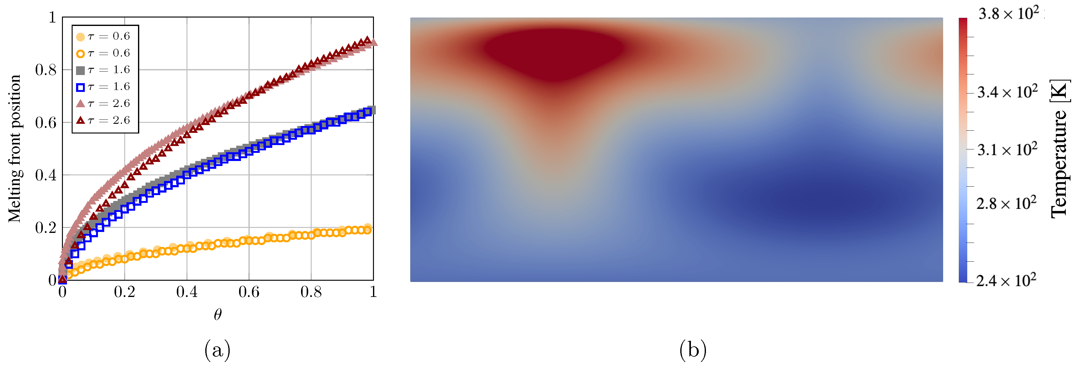
To validate the model, two classic benchmarks were considered, namely the 1D Stefan problem and the 2D Rayleigh–Bénard convection cell. For the 1D Stefan problem, we have reproduced the results in [28] for three values for thermal diffusivity: α = 0.033 , 0.36 , and 0.70 in lattice units. The cases provide the evolution of the melted front in a quasi-1D case, in which a hot wall melts the solid domain, in absence of gravity acceleration. The top and bottom boundaries are adiabatic, in this case. The Stefan number is the same as in [7,28], St = 1 , obtained through T s o l = 273.0 K, and T l i q = 352.5 K, in a 100 × 5 domain. Figure 2a reports the good matching in the 1D case.
Figure 2b shows the steady state plumes of temperature in a Rayleigh–Bénard convection cell. In this case, we consider the presence of gravity acceleration, with periodic boundary conditions on the sides of the domain. The top boundary is cold and the bottom boundary is hot. The simulations reproduce the density plumes due to the counter-action of gravity acceleration and buoyancy [40,41,42]. The case in Figure 2b refers to Ra 3 × 10 4 in a 128 × 64 domain.
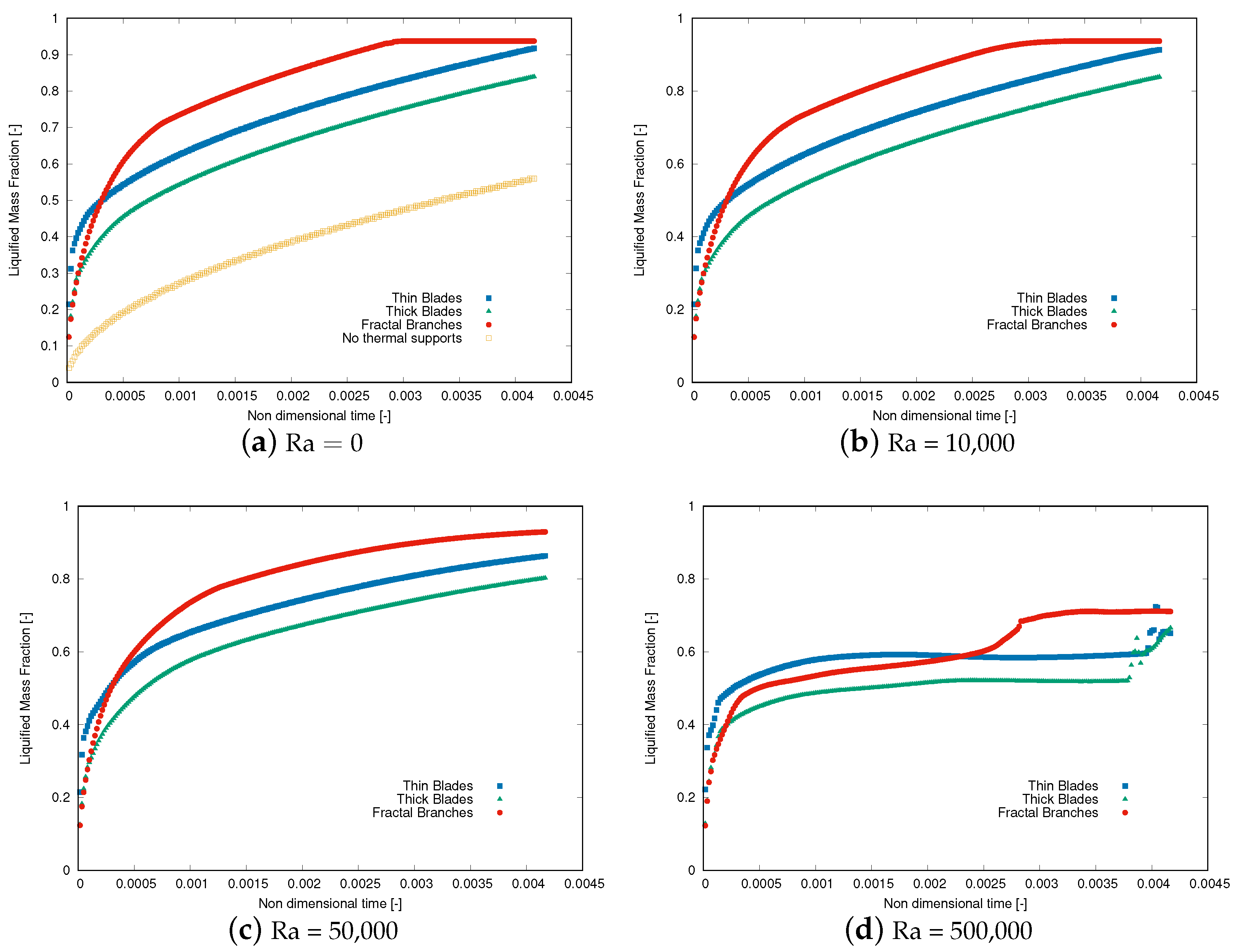
Considering the different thermal supports depicted in Figure 1, we report the evolution of the melted faction as a function of the non-dimensional time θ in Figure 3, for different values of the Ra number.
The panels in Figure 3 show that the fractal branches, even with the same mass as the fins and the blades and with the same temperature and thermal conductivity, are always characterized by a faster melting rate in the PCM matrix. This behavior is confirmed also at Ra = 500,000, in which the buoyancy effects become predominant and all the thermal supports show a lower performance compared to more moderate Ra values.
Figure 2. Validation tests for the LB solver: (a) evolution of the melting front in the 1D Stefan problem: in the panel, the filled symbols are taken from [33]; (b) steady state plumes of temperature in a 2D Rayleigh–Bénard convection cell [40,42].
Energies 16 06764 g002
Figure 3. Evolution in time of the liquefied mass fraction inside the computational domain. The effect of the different Ra numbers and of the solid thermal support morphology is apparent.
Energies 16 06764 g003
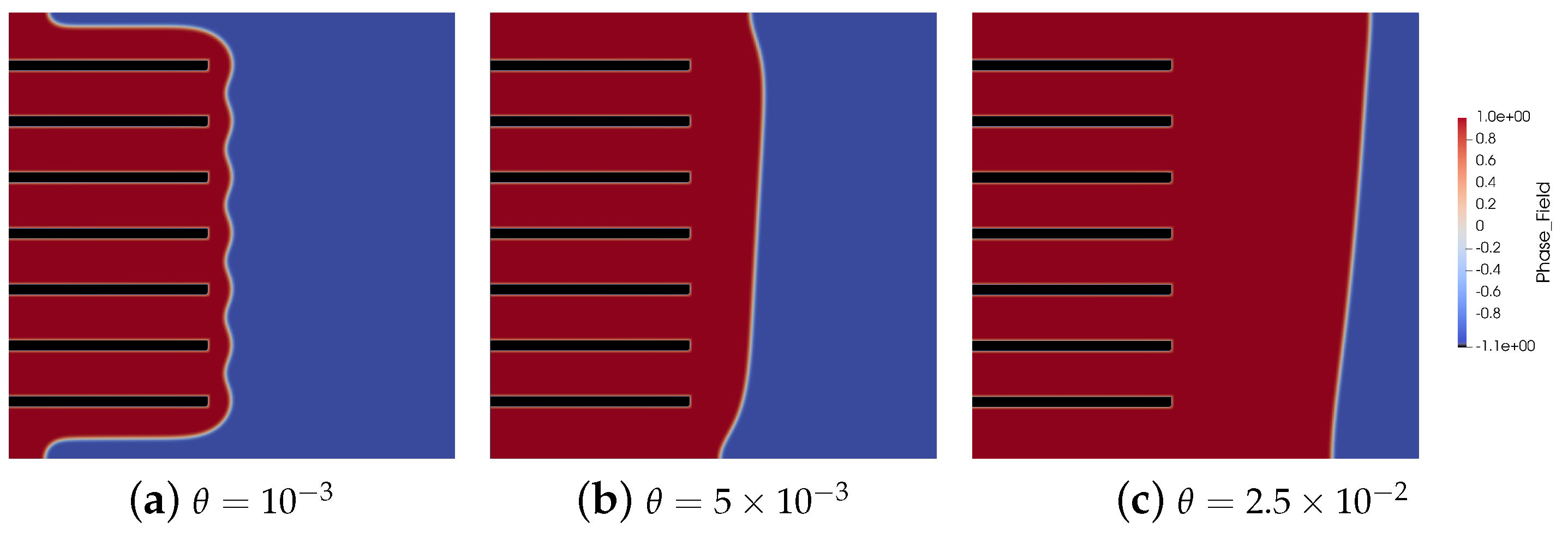
Figure 4 shows the evolution in time of the phase field ϕ parameter, which represents the liquid and melted phases in the computational domain, at Ra = 0 .
From the panel, it is apparent that the presence of thermal supports provides a remarkable increase in the melting rate (as reported in Figure 3a) and that the branched structure increases the melting rate compared to the fins and blades.
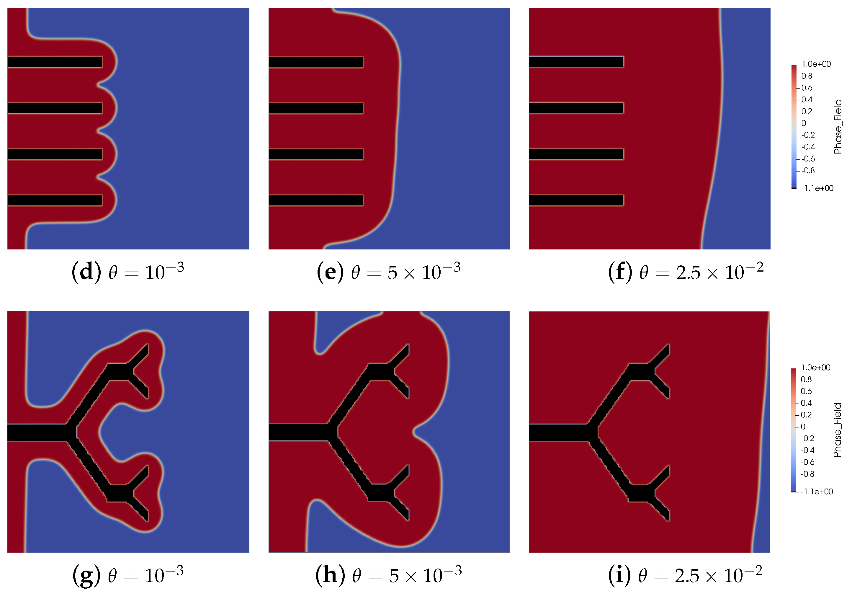
Figure 5 shows the evolution in time of the phase field ϕ parameter, which represents the liquid and melted phases in the computational domain, at Ra = 10,000.
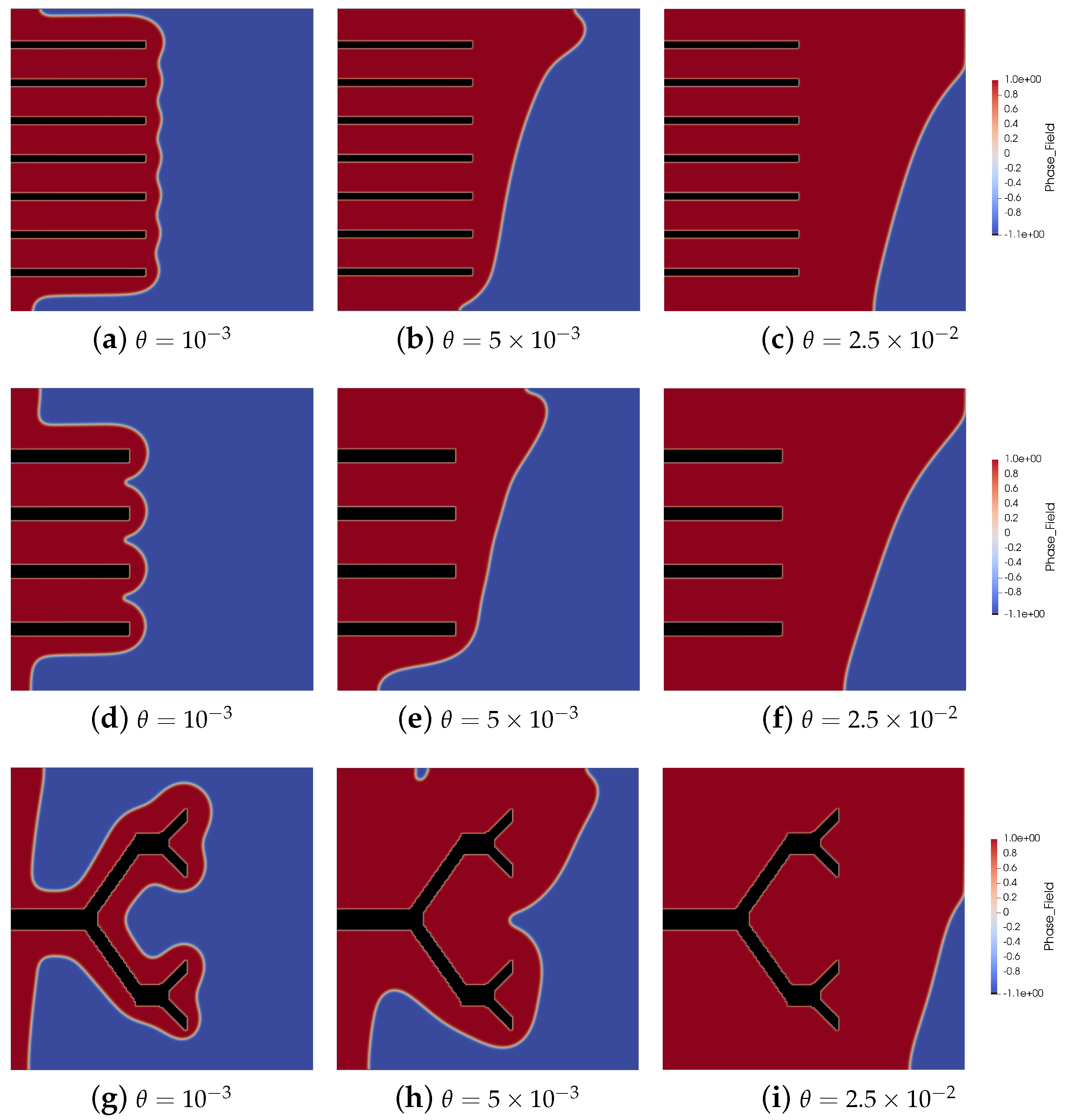
At such a regime, the effect of convection is already appreciable, leading to the development of a curved melting front in the upper part of the computational domain, as expected from the literature [7,43,44]. Additionally in this case, the branched thermal support provides the best energy transfer to the PCM matrix compared to the fins and blades. At Ra = 50,000, the convection contribution is still increased, as shown in Figure 6.
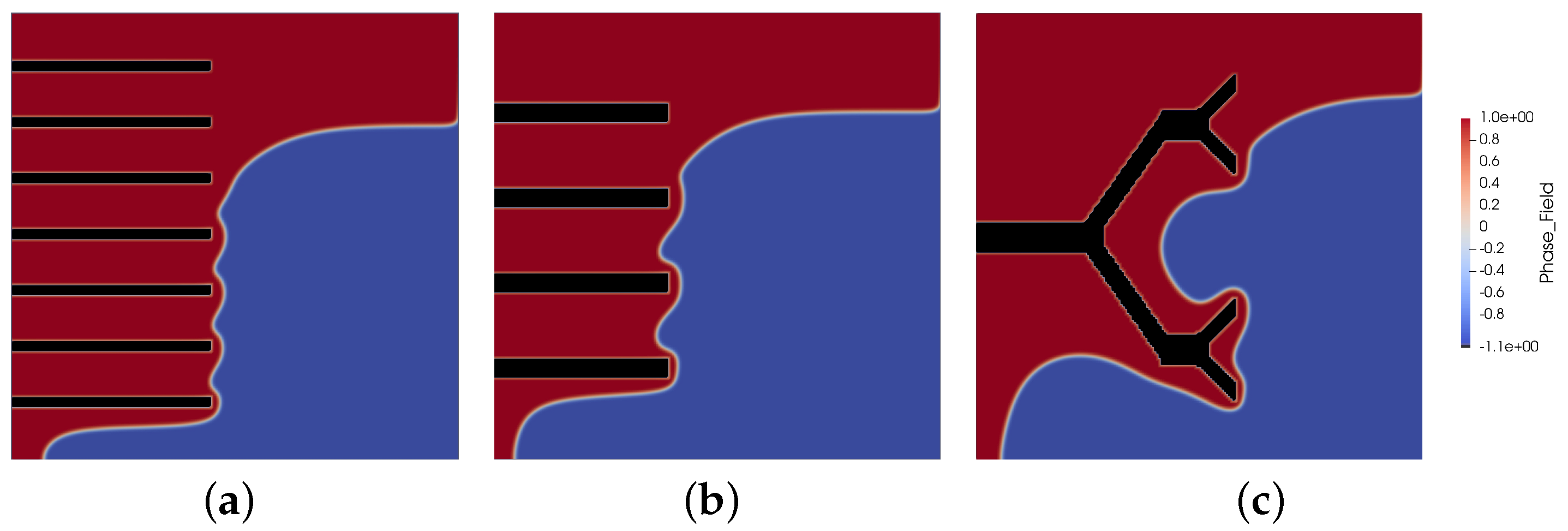
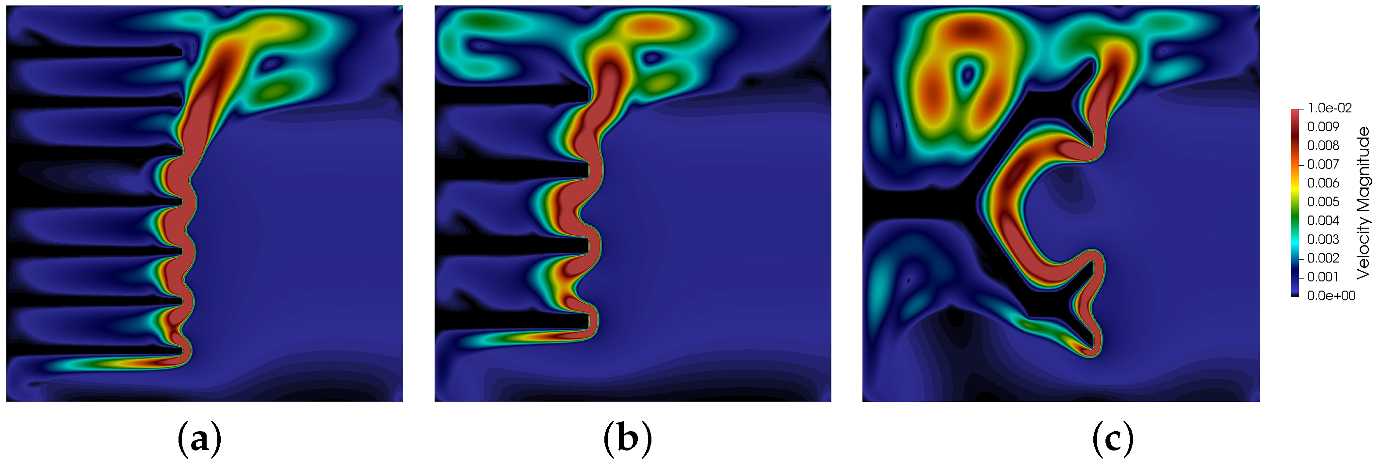
Figure 6 highlights the presence of secondary effects in the melting front due to the increased buoyancy. The variation in Ra , achieved through adjusting the module of g, causes the irregularities in the shape of the melting front, as expected from the literature for larger values of Ra [7,28,43,44]. Such effects are responsible for the anomalous performance reported in Figure 3d: to confirm this behavior, the phase field profiles at Ra = 500,000 for θ = 5 × 10 3 are reported in Figure 7. It is also interesting to look at the velocity magnitude profiles inside the computational domain at such a large Ra value, as reported in Figure 8.
Figure 8 highlights the presence of convective patterns inside the melted portion of the domain, in line with the numerical and experimental findings in the literature [28,43,44]. Such convective patterns are known to play an important role in the evolution of the melted front [7], confirming the capability of fractal branched structures to promote their onset, thus enhancing the system power performance.
We wish to stress the versatility and stability of our algorithm, which capitalizes on the lightness and reliability of the LBM, coupled to the remarkable stability of the phase-field plugin, which allows fast and trustworthy predictions even without resorting to extreme resolutions or refinement algorithms.

4. Conclusions

In this paper, we have presented a three-phase approach for PCM-enhanced LHTES systems. Our methodology is based on a thermal 2D LBM implementation coupled to a phase-field plugin for the evaluation of melting front evolution in time. The model is light and versatile, yet the preliminary results provide reliable predictions on the evolution of non-trivial systems, in line with what expected from the literature. We have applied our model to investigate the thermal conductivity enhancement of the PCM matrix in the presence of thermal conductive supports in the form of fins, blades, and novel, branched fractal structures. Considering thermal supports of equal mass temperature and thermal conductivity, the novel, fractal layout consistently outperforms the more traditional ones in terms of PCM melting rates, delivering higher power performance.
Our three-phase thermal lattice Boltzmann model, coupled with phase-field analysis, demonstrates the superiority of fractal, branch-like structures as thermal conductive supports, which contributes to improving the melting rate of PCM-TES systems. These findings hold promise for advancing the efficiency of thermal energy storage technologies.

Author Contributions

Conceptualization, G.F.; Software, G.A.; Investigation, G.A., S.S. and G.F.; Writing—original draft, G.A., S.S. and G.F. All authors have read and agreed to the published version of the manuscript.

Funding

G.F. wishes to acknowledge the support of the Italian Government Grants PRIN 2022F422R2 and PRIN P202298P25; S.S. acknowledges financial support from the European Research Council under the Horizon 2020 Programme Advanced Grant agreement no. 739964 (‘COPMAT’).

Data Availability Statement

All data and codes are available upon request to the corresponding author.

Acknowledgments

The authors wish to acknowledge and kindly thank Patrik Hoffmann, Head of the laboratory for Advanced Materials Processing, EMPA, Switzerland, for proposing the fractal approach for improving the total efficiency of the PCM in combination with hydrogen storage, and for fruitful discussions during the entire work.

Conflicts of Interest

The authors declare no conflict of interest.

References

  1. Mahon, H.; O’Connor, D.; Friedrich, D.; Hughes, B. A review of thermal energy storage technologies for seasonal loops. Energy 2022, 239, 122207. [Google Scholar] [CrossRef]
  2. IEA. Renewables. 2019. Available online: https://www.iea.org/reports/renewables-2019 (accessed on 22 February 2023).
  3. Gutierrez, A.; Miró, L.; Gil, A.; Rodríguez-Aseguinolaza, J.; Barreneche, C.; Calvet, N.; Py, X.; Fernández, A.I.; Grágeda, M.; Ushak, S.; et al. Advances in the valorization of waste and by-product materials as thermal energy storage (TES) materials. Renew. Sustain. Energy Rev. 2016, 59, 763–783. [Google Scholar] [CrossRef]
  4. Sadeghi, G. Energy storage on demand: Thermal energy storage development, materials, design, and integration challenges. Energy Storage Mater. 2022, 46, 192–222. [Google Scholar] [CrossRef]
  5. Gunasekara, S.N.; Barreneche, C.; Inés Fernández, A.; Calderón, A.; Ravotti, R.; Ristić, A.; Weinberger, P.; Ömur Paksoy, H.; Koçak, B.; Rathgeber, C.; et al. Thermal energy storage materials (TESMs)—What does it take to make them fly? Crystals 2021, 11, 1276. [Google Scholar] [CrossRef]
  6. Guo, S.; Liu, Q.; Zhao, J.; Jin, G.; Wu, W.; Yan, J.; Li, H.; Jin, H. Mobilized thermal energy storage: Materials, containers and economic evaluation. Energy Convers. Manag. 2018, 177, 315–329. [Google Scholar] [CrossRef]
  7. Facci, A.L.; Lauricella, M.; Succi, S.; Villani, V.; Falcucci, G. Optimized modeling and design of a PCM-enhanced H2 storage. Energies 2021, 14, 1554. [Google Scholar] [CrossRef]
  8. Cabeza, L.F.; Castell, A.; Barreneche, C.d.; De Gracia, A.; Fernández, A. Materials used as PCM in thermal energy storage in buildings: A review. Renew. Sustain. Energy Rev. 2011, 15, 1675–1695. [Google Scholar] [CrossRef]
  9. Cabeza, L.F. Advances in thermal energy storage systems: Methods and applications. In Advances in Thermal Energy Storage Systems; Elsevier: Amsterdam, The Netherlands, 2021; pp. 37–54. [Google Scholar]
  10. Nazir, H.; Batool, M.; Osorio, F.J.B.; Isaza-Ruiz, M.; Xu, X.; Vignarooban, K.; Phelan, P.; Kannan, A.M. Recent developments in phase change materials for energy storage applications: A review. Int. J. Heat Mass Transf. 2019, 129, 491–523. [Google Scholar] [CrossRef]
  11. Mahdi, J.M.; Lohrasbi, S.; Nsofor, E.C. Hybrid heat transfer enhancement for latent-heat thermal energy storage systems: A review. Int. J. Heat Mass Transf. 2019, 137, 630–649. [Google Scholar] [CrossRef]
  12. Sedeh, M.M.; Khodadadi, J. Thermal conductivity improvement of phase change materials/graphite foam composites. Carbon 2013, 60, 117–128. [Google Scholar] [CrossRef]
  13. Wei, G.; Wang, G.; Xu, C.; Ju, X.; Xing, L.; Du, X.; Yang, Y. Selection principles and thermophysical properties of high temperature phase change materials for thermal energy storage: A review. Renew. Sustain. Energy Rev. 2018, 81, 1771–1786. [Google Scholar] [CrossRef]
  14. Almonti, D.; Mingione, E.; Tagliaferri, V.; Ucciardello, N. Design and analysis of compound structures integrated with bio-based phase change materials and lattices obtained through additive manufacturing. Int. J. Adv. Manuf. Technol. 2021, 119, 149–161. [Google Scholar] [CrossRef]
  15. Warzoha, R.J.; Fleischer, A.S. Effect of graphene layer thickness and mechanical compliance on interfacial heat flow and thermal conduction in solid–liquid phase change materials. ACS Appl. Mater. Interfaces 2014, 6, 12868–12876. [Google Scholar] [CrossRef] [PubMed]
  16. Li, M.; Mu, B. Effect of different dimensional carbon materials on the properties and application of phase change materials: A review. Appl. Energy 2019, 242, 695–715. [Google Scholar] [CrossRef]
  17. Sarbu, I.; Dorca, A. Review on heat transfer analysis in thermal energy storage using latent heat storage systems and phase change materials. Int. J. Energy Res. 2019, 43, 29–64. [Google Scholar] [CrossRef]
  18. Succi, S. The Lattice Boltzmann Equation for Fluid Dynamics and Beyond; Clarendon: Oxford, UK, 2001. [Google Scholar]
  19. Krüger, T.; Kusumaatmaja, H.; Kuzmin, A.; Shardt, O.; Silva, G.; Viggen, E.M. The Lattice Boltzmann Method; Springer: Berlin/Heidelberg, Germany, 2017; Volume 10, pp. 978–983. [Google Scholar]
  20. Miller, W.; Succi, S.; Mansutti, D. Lattice Boltzmann model for anisotropic liquid-solid phase transition. Phys. Rev. Lett. 2001, 86, 3578. [Google Scholar] [CrossRef]
  21. Falcucci, G.; Amati, G.; Fanelli, P.; Krastev, V.K.; Polverino, G.; Porfiri, M.; Succi, S. Extreme flow simulations reveal skeletal adaptations of deep-sea sponges. Nature 2021, 595, 537–541. [Google Scholar] [CrossRef]
  22. Falcucci, G.; Polverino, G.; Porfiri, M.; Amati, G.; Fanelli, P.; Krastev, V.K.; Succi, S. Reply to: Models of flow through sponges must consider the sponge tissue. Nature 2022, 603, E26–E28. [Google Scholar] [CrossRef]
  23. Krastev, V.; Falcucci, G. Simulating engineering flows through complex porous media via the lattice Boltzmann method. Energies 2018, 11, 715. [Google Scholar] [CrossRef]
  24. Falcucci, G.; Chiatti, G.; Succi, S.; Mohamad, A.A.; Kuzmin, A. Rupture of a ferrofluid droplet in external magnetic fields using a single-component lattice Boltzmann model for nonideal fluids. Phys. Rev. E Stat. Nonlinear Soft Matter Phys. 2009, 79, 056706. [Google Scholar] [CrossRef]
  25. Sbragaglia, M.; Benzi, R.; Biferale, L.; Succi, S.; Sugiyama, K.; Toschi, F. Generalized lattice Boltzmann method with multirange pseudopotential. Phys. Rev. E 2007, 75, 026702. [Google Scholar] [CrossRef] [PubMed]
  26. Falcucci, G.; Bella, G.; Chiatti, G.; Chibbaro, S.; Sbragaglia, M.; Succi, S. Lattice Boltzmann Models with Mid-Range Interactions. Comm. Comput. Phys. 2007, 2, 1071–1084. [Google Scholar]
  27. Colosqui, C.E.; Falcucci, G.; Ubertini, S.; Succi, S. Mesoscopic simulation of non-ideal fluids with self-tuning of the equation of state. Soft Matter 2012, 8, 3798–3809. [Google Scholar] [CrossRef]
  28. Huber, C.; Parmigiani, A.; Chopard, B.; Manga, M.; Bachmann, O. Lattice Boltzmann model for melting with natural convection. Int. J. Heat Fluid Flow 2008, 29, 1469–1480. [Google Scholar] [CrossRef]
  29. Pareschi, G.; Frapolli, N.; Chikatamarla, S.S.; Karlin, I.V. Conjugate heat transfer with the entropic lattice Boltzmann method. Phys. Rev. E 2016, 94, 013305. [Google Scholar] [CrossRef]
  30. Chiappini, D.; Donno, A. A comparison between different fractal grid generation methods coupled with lattice Boltzmann approach. AIP Conf. Proc. 2016, 1738, 270003. [Google Scholar]
  31. Chiappini, D. A coupled lattice Boltzmann-finite volume method for phase change material analysis. Int. J. Therm. Sci. 2021, 164, 106893. [Google Scholar] [CrossRef]
  32. Wu, S.; Yan, T.; Kuai, Z.; Pan, W. Thermal conductivity enhancement on phase change materials for thermal energy storage: A review. Energy Storage Mater. 2020, 25, 251–295. [Google Scholar] [CrossRef]
  33. Joshi, V.; Rathod, M.K. Experimental and numerical assessments of thermal transport in fins and metal foam infused latent heat thermal energy storage systems: A comparative evaluation. Appl. Therm. Eng. 2020, 178, 115518. [Google Scholar] [CrossRef]
  34. Li, J.; Zheng, Y.; Liu, X. Enhancing discharging performance of a phase change thermal storage unit with a fractal space-filling matrix. J. Renew. Sustain. Energy 2021, 13, 014102. [Google Scholar] [CrossRef]
  35. Yu, C.; Wu, S.; Huang, Y.; Yao, F.; Liu, X. Charging performance optimization of a latent heat storage unit with fractal tree-like fins. J. Energy Storage 2020, 30, 101498. [Google Scholar] [CrossRef]
  36. Succi, S. The Lattice Boltzmann Equation: For Complex States of Flowing Matter; Oxford University Press: Oxford, UK, 2018. [Google Scholar]
  37. Ben Ltaifa, K.; D’Orazio, A.; Dhahri, H. Numerical analysis of mixed convection heat transfer and laminar flow in a rectangular inclined micro-channel totally filled with Water/Al2O3 Nano fluid. J. Therm. Anal. Calorim. 2021, 144, 2465–2482. [Google Scholar] [CrossRef]
  38. Miller, W.; Succi, S. A lattice Boltzmann model for anisotropic crystal growth from melt. J. Stat. Phys. 2002, 107, 173–186. [Google Scholar] [CrossRef]
  39. D’Orazio, A.; Karimipour, A.; Mosavi, A. Develop lattice Boltzmann method and its related boundary conditions models for the benchmark oscillating walls by modifying hydrodynamic and thermal distribution functions. Eur. Phys. J. Plus 2020, 135, 915. [Google Scholar] [CrossRef]
  40. Chandrasekhar, S. Hydrodynamic and Hydromagnetic Stability; Courier Corporation: Chelmsford, MA, USA, 2013. [Google Scholar]
  41. Chaabane, R.; Kolsi, L.; Jemni, A.; Alshammari, N.K.; D’Orazio, A. Numerical study of the Rayleigh–Bénard convection in two-dimensional cavities heated by elliptical heat sources using the lattice Boltzmann method. Phys. Fluids 2021, 33, 123605. [Google Scholar] [CrossRef]
  42. Pelusi, F.; Lulli, M.; Sbragaglia, M.; Bernaschi, M. TLBfind: A Thermal Lattice Boltzmann code for concentrated emulsions with FINite-size Droplets. Comput. Phys. Commun. 2022, 273, 108259. [Google Scholar] [CrossRef]
  43. Jany, P.; Bejan, A. Scaling theory of melting with natural convection in an enclosure. Int. J. Heat Mass Transf. 1988, 31, 1221–1235. [Google Scholar] [CrossRef]
  44. Bertrand, O.; Binet, B.; Combeau, H.; Couturier, S.; Delannoy, Y.; Gobin, D.; Lacroix, M.; Le Quéré, P.; Médale, M.; Mencinger, J.; et al. Melting driven by natural convection A comparison exercise: First results. Int. J. Therm. Sci. 1999, 38, 5–26. [Google Scholar] [CrossRef]
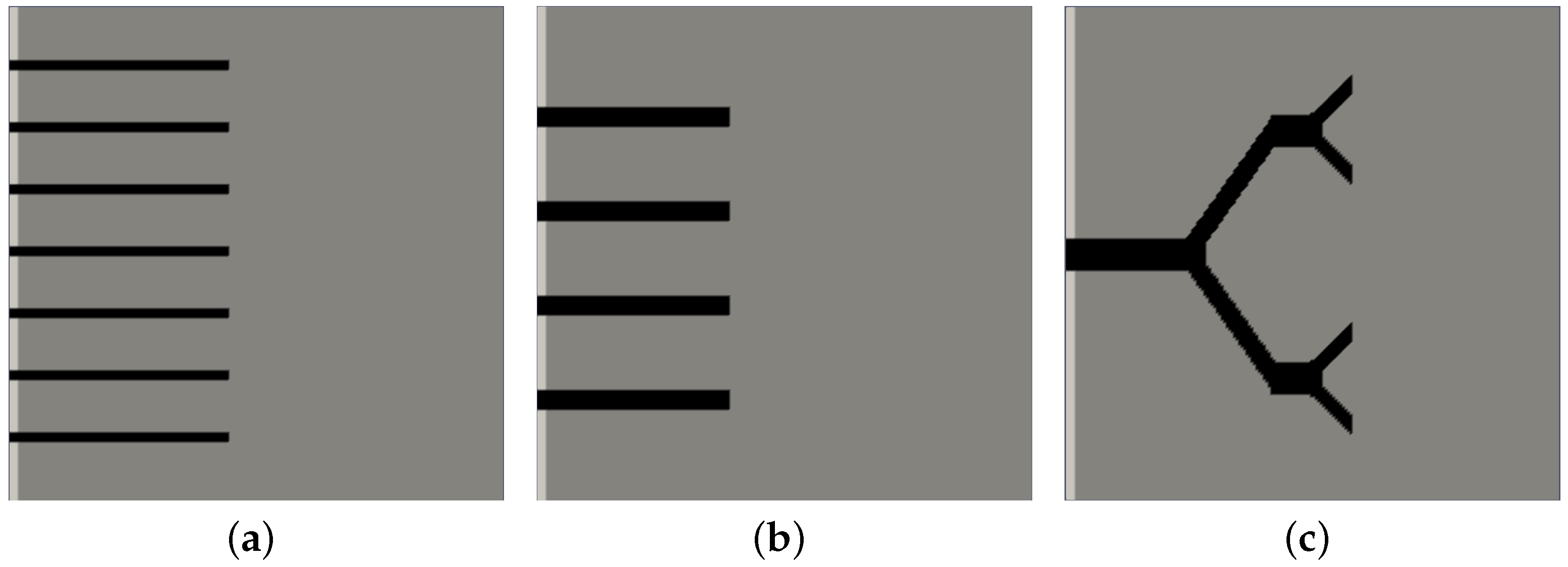
Figure 1. Sketch of the different morphologies of solid thermal support: (a) thin fins; (b) thick blades; (c) branched fractal structure. The three structures are characterized by the same mass, the same thermal conductivity, and the same temperature.
Energies 16 06764 g001
Figure 4. Evolution in time of the phase field parameter ϕ as a function of the non-dimensional time θ . All panels refer to the cases at Ra = 0 .
Energies 16 06764 g004
Figure 5. Evolution in time of the phase field parameter ϕ as a function of the non-dimensional time θ . All panels refer to the regime at Ra = 10,000.
Energies 16 06764 g005aEnergies 16 06764 g005b
Figure 6. Evolution in time of the phase field parameter ϕ as a function of the non-dimensional time θ . All panels refer to the regime at Ra = 50,000.
Energies 16 06764 g006
Figure 7. (ac) Snapshots of the melting front position at Ra = 500,000 and θ = 5 × 10 3 .
Energies 16 06764 g007
Figure 8. Contours of the velocity magnitude inside the computational domain for the three investigated geometries (ac) at Ra = 500,000 and θ = 5 × 10 3 .
Energies 16 06764 g008
Disclaimer/Publisher’s Note: The statements, opinions and data contained in all publications are solely those of the individual author(s) and contributor(s) and not of MDPI and/or the editor(s). MDPI and/or the editor(s) disclaim responsibility for any injury to people or property resulting from any ideas, methods, instructions or products referred to in the content.