Article

Experimental Validation of Iterative Learning Control for DC/DC Power Converters

School of Automation, Northwestern Polytechnical University, Xi’an 710072, China
*
Author to whom correspondence should be addressed.
Energies 2023, 16(18), 6555; https://doi.org/10.3390/en16186555
Submission received: 27 July 2023 / Revised: 31 August 2023 / Accepted: 7 September 2023 / Published: 12 September 2023
(This article belongs to the Section D: Energy Storage and Application)

Abstract

:
In order to solve the problem that the parameters of traditional proportional–integral (PI) control are not easy to adjust, an iterative learning control (ILC) technique for a DC/DC power converter is proposed in this paper. Firstly, we have developed a system which is composed of two different states of DC/DC converter in order to obtain its equivalent linear time-varying system, and then the open-loop PD-type ILC law has been used to control it. Secondly, an experimental setup is arranged to verify and compare the simulated results. The experimental results show that, as compared with the traditional PI control, the proposed strategy is easy to implement and optimal with regard to debugging parameters, and it can achieve zero steady-state tracking errors without overshooting. Finally, the experimental results have also proven that our proposed scheme of iterative learning control for a DC/DC power converter is robust as compared to traditional PI control.

1. Introduction

In the era of the rapid development of national industry and technology, DC/DC power converters [1] are widely used in photovoltaic power generation [2], hybrid electric vehicles [3], DC micro-grid systems [4], energy-saving elevator systems [5,6,7], and other fields. The most common control method for DC/DC power converters is traditional PID control. This method has its inherent advantages, but it is prone to overshooting and difficult to adjust parameters [8]. In addition, it is difficult to achieve no static error tracking. In recent years, many scholars have proposed many improvement schemes based on traditional PID control. In [9], Li et al. proposed sliding-mode PID control and discussed how to choose the optimal sliding-mode PID parameters. Guo et al. discussed the feasibility of fuzzy PID control for a DC/DC power converter in [10]. Subsequently, a different researcher introduced an adaptive PID algorithm grounded on a Gaussian function [11]. This algorithm was then applied to the DC/DC power converter. Meanwhile, in [12], Malik et al. presented a process model and a method for selecting the P, I, and D parameters based on dynamic model parameters. Although many scholars have made a lot of achievements in controlling DC/DC converters, such control methods are relatively complicated and difficult to use. Therefore, this paper proposes a new control method for DC/DC power converters using ILC.
In a broad sense, learning control is a kind of intelligent control that has self-regulation and learning functions. Let us start with a practical example: crane operators. Operators receive comprehensive training. Through both instructional and non-instructional learning, they transition from a state of limited understanding to becoming proficient technicians after consistent practice. Many scholars have investigated power control techniques using different schemes, such as sliding-mode control, for performance analysis [13,14]. Obviously, learning control has an important role in processing. Unfortunately, in the theoretical field, a complete model and understanding of the human learning process and mechanism, especially in terms of optimization, have not yet been established [15,16]. Learning is an interdisciplinary concept linked to biology, brain science, and all other disciplines related to life. The concept of learning has been extended to machine learning in the fields of mathematics and engineering, and it is very necessary for a definition of learning to be given in control theory and control engineering. Learning in control can be generally divided into three types: single-objective accurate learning [17], pattern-based multi-objective learning (statistical learning) [18], and quantitative biological learning (bio-learning) [19]. Learning control is a combination of these three types of learning and control. Therefore, learning control is a very meaningful subject worthy of our study because it can be widely used in human production and life, and it is a subject favored by many scholars [6,20,21].
So far, there have been several definitions of learning, and they describe different methods of learning. A more concrete and vivid summary of learning methods should be the definition of “Learning by Trials”. In general, the learning strategy given in the definition of “learning by repetition” is the accumulation of experience. For example, learning is “a long-term change in the system to adapt to the environment, which enables the system to do the same or similar work more efficiently the next time” (D Hoehler) [22]. “The term learning in a system is understood to mean the process of giving a system a specific response to a specific input signal (input action) by repeating input signals and correcting the system externally” (Y.Z.Tsypkin), and so on [23,24].
ILC is a kind of learning control. This control method was first proposed by the Japanese scholar Uchiyama in 1978, and a breakthrough development was made in 1984 [25]. The principle of ILC control involves using errors measured from prior instances or errors from multiple previous times to adjust the control input. This adjustment ensures that the output signal closely aligns with the expected one accurately [6,20,26,27,28]. The core of this algorithm is to learn from previous iterative tasks to improve the output for the next step [29]. ILC does not need an accurate mathematical model of the controlled system [30,31] and requires less prior knowledge and computation. Therefore, this control method is of great significance to the study of nonlinear, strong coupling, difficult-to-model, and high-precision trajectory control problems [32,33]. So far, ILC has been widely used in many high-precision controls [34,35,36,37,38]. ILC is also used in many energy storage systems, as well as for frequency and voltage stabilization, as mentioned in the literature [39,40]. ILC has been successfully implemented for grid-connected PV systems [41]. Still, there is a research gap in that nobody has implemented ILC for the buck DC/DC converter. Therefore, in this study, we aimed to use and validate the practical implementation of ILC for a DC/DC power converter.
The main contribution of the study is summarized as follows:
In this paper, the open-loop PD-type ILC law is used to control the buck DC/DC converter. The key features of our proposed control are as follows:
  • To switch the buck DC/DC converter into a switching system consisting of two different states of on and off and to use the switching-period average operator and the state-space average method to create the equivalent of a linear time-varying continuous circuit. Its conversion rule is determined by the duty cycle of the switch tube control signal.
  • The system is controlled by an open-loop PD-type ILC. In addition to using ILC to control the buck DC/DC converter, the results are compared with traditional PI control.
  • This paper also uses the traditional PI-type buck converter control method and compares and analyzes the control effects of both control techniques. One can see from the simulation and experimental results that the ILC has obvious advantages compared with the traditional PI control.
The remainder of this proposed study is arranged as follows: Section 2 analyzes the mathematical model of the buck DC/DC converter and its equivalent system. Section 3 offers the method and proof of iterative learning control. Section 4 gives the specific implementation process of iterative learning control. Section 5 elaborates the simulation example and the real experimental results, which have proven the superiority of our proposed method. Section 6 concludes this research article.

2. Modeling of the Buck Converter and Problem Statement

2.1. Modeling of Buck Converter Based on Traditional Control

The Figure 1 below shows the basic topology of the traditional control of the buck converter.
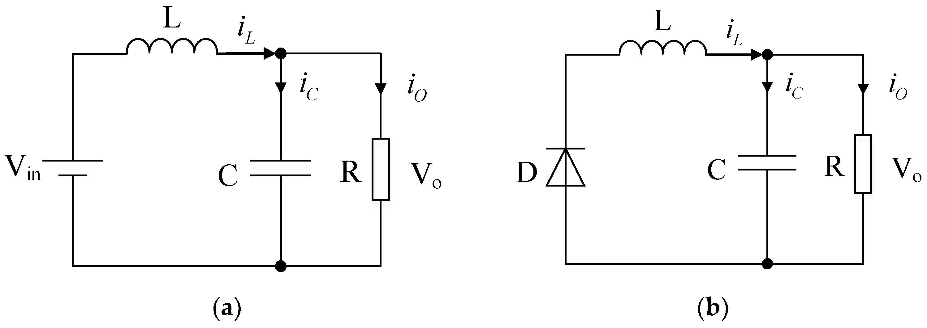
In this section, we have to establish a mathematical model for the better control of the buck converter. The equivalent circuit of two different switching states of the buck converter has been given below (see Figure 2 below), and the traditionally controlled buck converter will be mode led according to the equivalent circuit.

2.1.1. Formation of Model in Broader Perspective

When the switch tube is turned on, the equation can be listed according to the voltage across the inductor and the capacitor current becomes the following:
u L ( t ) = L d i L ( t ) d t = V i n ( t ) V o ( t ) i c ( t ) = C d u c ( t ) d t = i L ( t ) V o ( t ) R
In the formula u L ( t ) , i L ( t ) , u c ( t ) , i c ( t ) , L , and C are the inductor voltage, inductor current, capacitor voltage, capacitor current, inductor value, and capacitor value. V i n ( t ) and V o ( t ) are the input voltage and output voltage.
When the switch tube is turned off, the equation can be listed according to the voltage across the inductor and the capacitor current:
u L ( t ) = L d i L ( t ) d t = V o ( t ) i c ( t ) = C d u c ( t ) d t = i L ( t ) V o ( t ) R
If the duty cycle of the switching tube control signal is d ( t ) , multiply the Formula (1) by ( 1 d ( t ) ) and at the same time multiply Formula (2), respectively, adding and simplifying the calculated two formulas to achieve the following:
L d i L ( t ) d t = d ( t ) V i n ( t ) V o ( t ) C d u c ( t ) d t = i L ( t ) V o ( t ) R
Formula (3) is the broader perspective generalized model of the buck converter.

2.1.2. Formation of Small Signal Model

If a small disturbance V i n , d , is added to the input voltage, V i n , and duty cycle, that is
V i n ( t ) = V i n + V i n d ( t ) = D + d
It will cause small changes in the state variables of the buck converter, specifically
i L ( t ) = I L + i L u c ( t ) = U c + u c i g ( t ) = I g + i g
where i g ( t ) is the input current.
Substitute (4) and (5) into (3) to achieve the small signal disturbance model:
L d ( I L + i L ) d t = ( D + d ) ( V i n + V i n ) V o ( t ) C d ( U c + u c ) d t = I L + i L V o ( t ) R
The input current equation is
I g + i g = ( D + d ) ( I L + i L )
Neglecting the high-order infinitesimal term and the steady-state term, the small-signal model has been obtained as follows:
L d ( i L ) d t = D V i n + d V i n V o ( t ) C d ( u c ) d t = i L V o ( t ) R i g = D i L + I L d
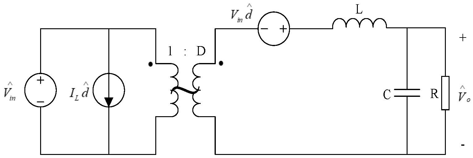
This shows that we have derived an AC small-signal equivalent model of the buck converter in the mentioned Formula (8). And the equivalent circuit can be seen in the following Figure 3.

2.2. Design of Traditional PI Controller

This section demonstrates the open-loop transfer function of a buck converter. It is given as follows:
G v d ( s ) = V i n 1 + s L R + s 2 L C
Taking V i n = 24 V, L is 35 uH, C is 880 uF, R is 51 Ω, and by substituting the derived values into Formula (9), we could obtain the following:
G v d ( s ) = 24 3.08 × 10 8 s 2 + 6.86 × 10 7 s + 1
Now we can draw the bode plot of the above transfer function using the MATLAB simulation. This is demonstrated in the following Figure 4:
Design a PI controller to compensate for an open-loop bode plot using MATLAB’s “sisotool” toolbox.
We can conclude that our design is complete so we can further demonstrate the transfer function in the following form:
G c ( s ) = 9.18 × 10 4 s 2 + 10.5 s + 3 × 10 4 2.4 × 10 13 s 4 + 3.08 × 10 8 s 3 + 8.486 × 10 6 s 2 + s
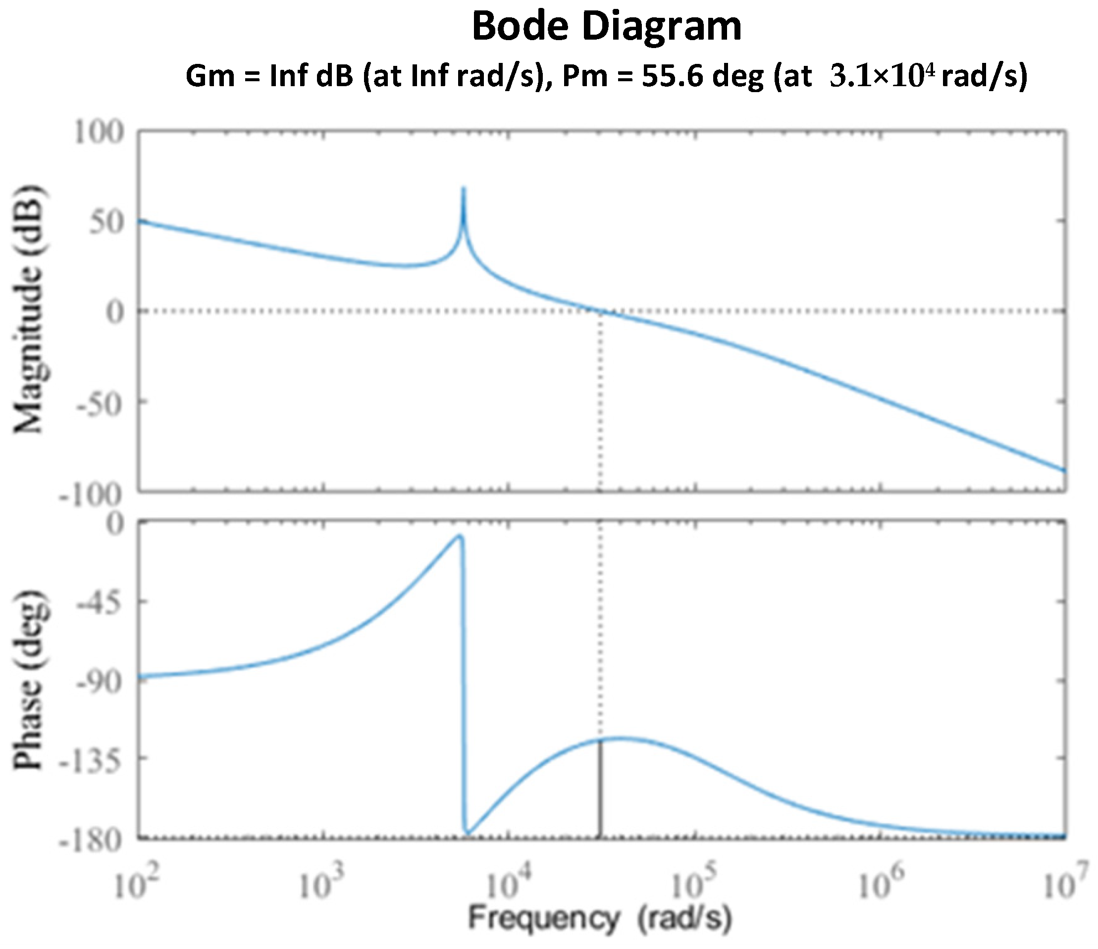
The following figure depicts the bode diagram of the system derived in Formula (11). It is shown in Figure 5 as follows:
The switching frequency used by the buck converter described in this paper is f s = 25   kHz , as can be seen from the bode diagram; the corrected crossover frequency is f c = 4.9   kHz < 1 5 f s , and the phase margin is γ = 55.6 ° > 45 ° , so the corrected system is stable, and the PI controller design is reasonable.
The above method is called the traditional PI controller design. Although the design of the PI controller has theoretical support, in order to achieve high dynamic and high steady-state performance, it is necessary to achieve a compromise between various parameters, and it is hard to debug parameters and obtain the optimal matching effect. Iterative learning control can solve this problem very well.

2.3. Modeling of Buck Converter Based on Iterative Learning Control

In Section 2.1, the traditionally controlled buck converter model is given. The iterative learning-controlled buck converter model is given below.
When the switch tube Q is off:
L d i L d t = u C C d u C d t + u C R = i L
When the switch tube Q is on:
L d i L d t + u C = V i n C d u C d t + u C R = i L
Let x 1 = i L , x 2 = u C , x 1 · = d i L d t , x 2 · = d u C d t , then the equation of state can be obtained from Formulas (12) and (13):
x 1 · x 2 · = 0 1 L 1 C 1 R C x 1 x 2 + 0 0 V i n
x 1 · x 2 · = 0 1 L 1 C 1 R C x 1 x 2 + 1 L 0 V i n
To write in the order for the convenience A 1 = 0 1 L 1 C 1 R C , A 2 = 0 1 L 1 C 1 R C , B 1 = 0 0 , B 2 = 1 L 0 , X = x 1 x 2 , Then, the above formula can be written as
x 1 · x 2 · = A 1 X + B 1 V i n
x 1 · x 2 · = A 2 X + B 2 V i n
The above Formulas (16) and (17) are the mathematical model of the buck converter. It is assumed that the system formed by Formula (16) is system A, and the system formed by Formula (17) is system B, then a typical switching system can be formed by subsystem A and subsystem B. Additionally, the respective switching rules are determined by the duty cycle. This can be seen in the following Figure 6.
The switching system operates with cycle T of the PWM because it is impossible for the actual trajectory to track the desired one for the whole duration during the actual operation. It is very important to track the desired trajectory within the given interval (see Figure 6). This paper adopts the middle time point of system A, i.e., time t 1 2 ; the middle time point of system B, specifically, the total taken time is t 1 + T t 1 2 . The tracking through these two points realizes the mean value tracking of the output system on the period T. Controlling the tracking of the middle time point of the two systems A and B is controlled by controlling the action time of the two systems, that is, controlling the duty cycle.
It can be seen from the above derivation that when the switching system is running, the switching rule determined by the duty cycle coordinates the mutual conversion between subsystem A and subsystem B. It also affects the action time of each subsystem. The switching rule largely determines whether the desired trajectory can be accurately tracked, and it also disturbs the state stability of the switching system.
We are now able to propose the ILC of the buck converter, whereby the switching system is equivalent to a linear, time-varying system using the state-space averaging method. We can demonstrate the state equation of a DC/DC converter as an equivalent system in the following way:
X · = A 2 X + ( 1 u ) B 2 V i n = 0 1 L 1 C 1 R C X + ( 1 u ) 1 L 0 V i n
Y = 0 1 X
From the analysis of the above formula, it can be known that although the system is time-varying, it is periodic, and the period is T, so the system can easily be controlled using ILC.

3. Iterative Learning Control Scheme

3.1. Fundamentals of ILC Control

In this section, we are assuming that the dynamic process of the repeated operation system for the period of t [ 0 , T ] , which is demonstrated as follows:
x · ( t ) = f [ t , x ( t ) , u ( t ) ] y ( t ) = g [ t , x ( t ) , u ( t ) ]
It is given in above formula that x R n × 1 , y R m × 1 , and u R r × 1 are vector functions of corresponding dimensions, and their structures and parameters are unknown. If desired control exists u d ( t ) , then our main purpose of ILC is to provide the expected output and the initial state of each operation x k ( 0 ) ; this is required to make the control input u k ( t ) u d ( t ) through multiple repeated operations according to a certain learning law within a given time t [ 0 , T ] , and the system output must track the desired trajectory such as y k ( t ) y d ( t ) . Equation (20) in k time iteration is expressed as follows:
x k ( t ) = f [ t , x k ( t ) , u k ( t ) ] y k ( t ) = g [ t , x k ( t ) , u k ( t ) ]
The output tracking error is as follows:
e k ( t ) = y d ( t ) y k ( t )
From Equation (22), we can conclude that the subscript k signifies the value of the kth run.
We have assumed that ILC is an open-close loop learning control for the buck converter. Since the open-loop PD-type ILC law is used in this study, we can demonstrate the elementary block diagram of the proposed open-loop ILC, which is given below in Figure 7.

3.2. Learning Law of Proposed ILC

This paper adopts an open-loop PD-type iterative learning control, and its basic learning law is as follows:
u k + 1 ( t ) = u k ( t ) + k P e k ( t ) + k D ( e k ( t ) e k ( t 1 ) )
In the formula u k + 1 ( t ) , u k ( t ) are the control quantities of the k + first and kth times, respectively, e k ( t ) represents an error term of the kth run, e k ( t 1 ) is the error of one sampling time behind the kth time, k P is the proportional gain, and k D is the differential gain.
We can now demonstrate the implemented block diagram of the ILC, which is described as follows:
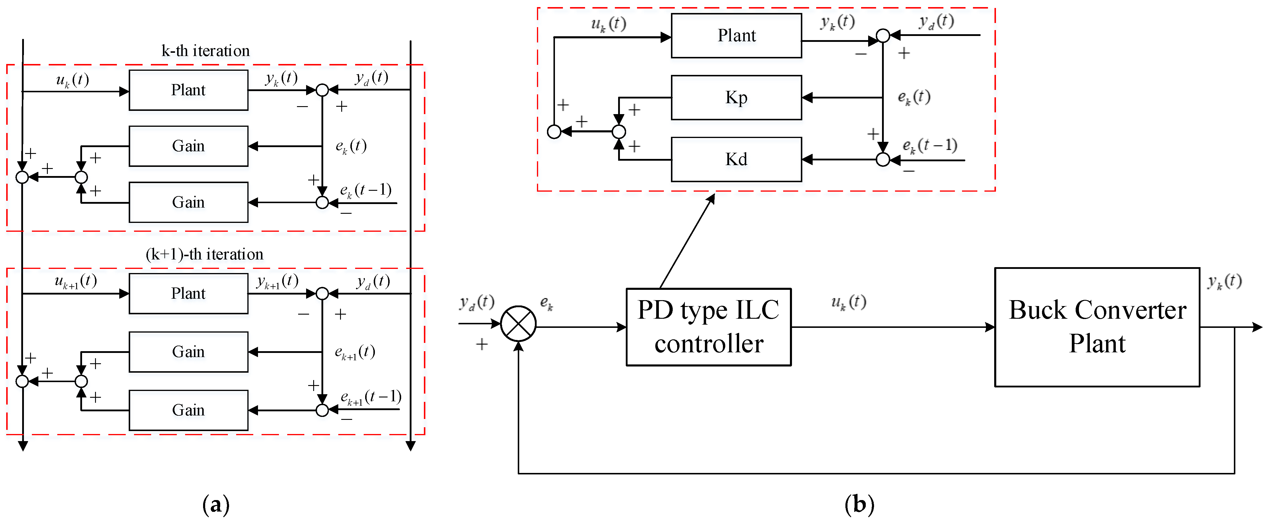
Figure 8a shows the concept of a PD-type ILC for a buck converter, while Figure 8b shows the overall control for the power converter. Figure 8b represents the kth time control of ILC where k P is the proportional gain and k D is the differential gain of the proposed PD-type ILC control.

4. Implementation of Iterative Learning Control for Buck Converter

4.1. System Schematic Structure

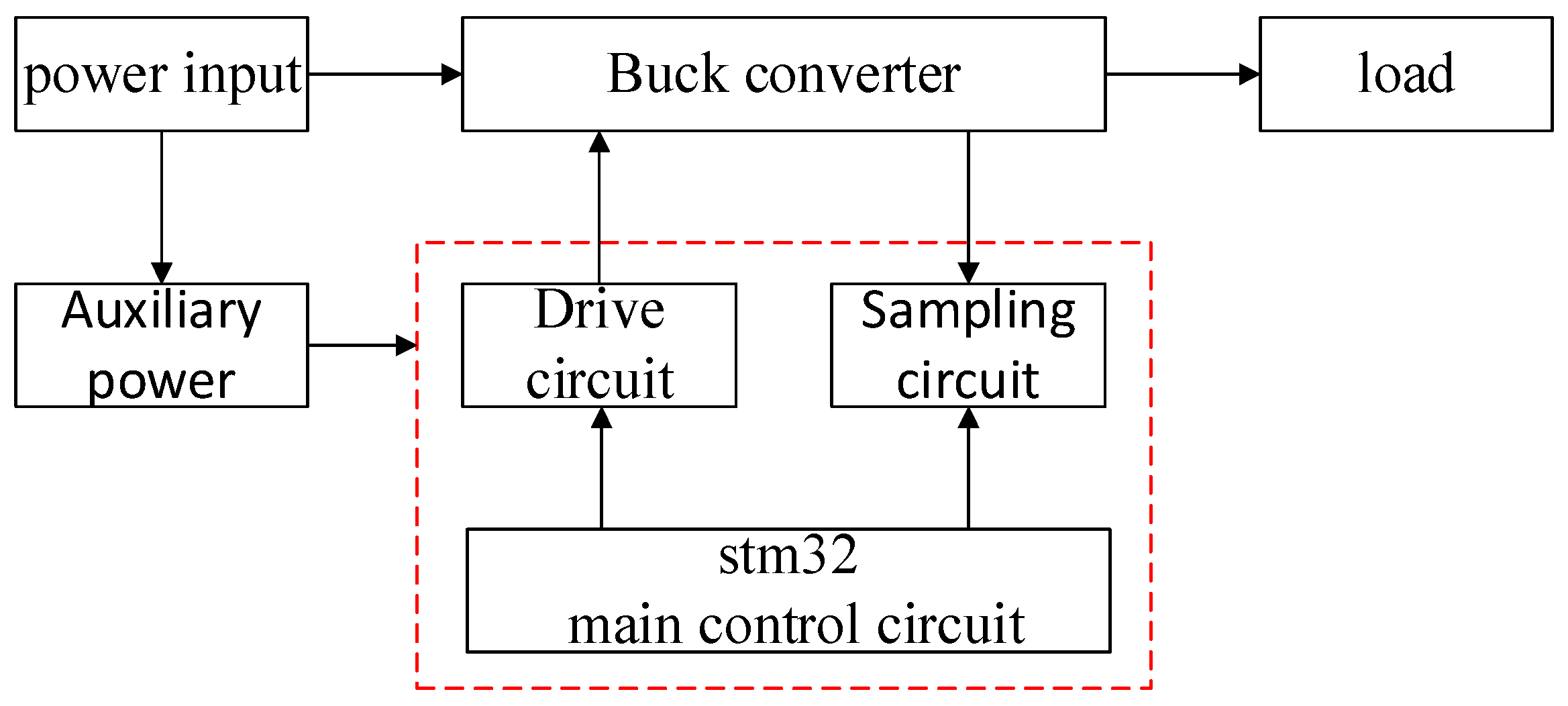
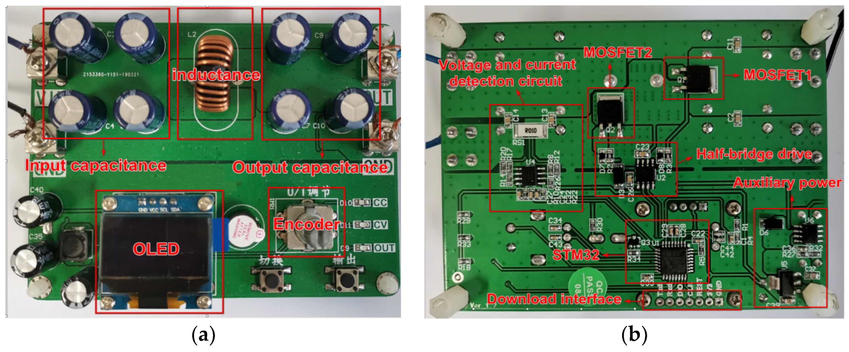
The buck digital control board used in this paper is composed of a buck topology circuit, an auxiliary power supply, an MOS tube drive circuit, a signal acquisition circuit, and an STM32 main control circuit. Its structural block diagram is shown in the following Figure 9. While the respective physical setup representation is shown in Figure 10.

4.2. Sampling Filtering Method

Due to the needs of ILC and to make the sample values used in the calculation more accurate, this paper adopts the following sampling filtering method: sampling 40 times in one PWM cycle (40 us), and then using the switching period average operator to compare the 40 samples, the sampled values are averaged. The calculated average is the value to be used each time. In order to reduce the amount of calculation, 40 pieces of data are divided into four groups, and each group contains 10 pieces of data. When calculating the average value, first calculate the average value of each group, and then calculate the average value within one PWM period. Of course, the moving average filter adopted is also performed in units of groups. Its realization process is
a v e r a g e [ i ] = v ( t + 10 i × T S ) + v ( t + T S + 10 i × T S ) + v ( t + 2 T S + 10 i × T S ) + + v ( t + 9 T S + 10 i × T S ) 10
We can conclude from the formula that i denotes the number of groups mentioned above, and its value can be 0, 1, 2, and 3. T S represents the sampling time; v ( t ) depicts the sampling value; and a v e r a g e [ i ] signifies the average value of each group. Then, calculate the average value in each PWM cycle by the following formula:
a v e r a g e = a v e r a g e [ 0 ] + a v e r a g e [ 1 ] + a v e r a g e [ 2 ] + a v e r a g e [ 3 ] 4
It is concluded that a v e r a g e means the average value in one PWM period. Finally, the moving average filtering calculation is carried out in units of groups to realize iterative learning control.

4.3. Implementation of Iterative Control Learning

It can be seen from the above that this article samples 40 times in a PWM cycle, and then divides them into groups of 10 times. Therefore, it is necessary to perform four-beat iterative operation control on the buck converter within a PWM cycle. Its specific calculation principle is as follows
u k + 1 ( j ) = u k ( j ) + k P e k ( j ) + k D ( e k ( j ) e k ( j 1 ) )
In the formula, u k ( j ) is the control amount of the j-th beat of the kth time, u k + 1 ( j ) is the control amount of the j-th beat of the k + first time, e k ( j 1 ) is the deviation of the j-th beat of the k-th time and is the deviation of the j − 1th beat of the k-th time, and the value of j can be 1, 2, 3, and 4. Then, apply the above formula as shown in Figure 11 below.
The above is the basic calculation principle of iterative learning control. In the actual use process, it is necessary to adjust the proportional coefficient k P and the differential coefficient k D to optimize the system effect. After completing the above steps, the iterative control of the buck converter can be realized.

5. Main Simulation Results and Analysis

5.1. Simulation Verfication

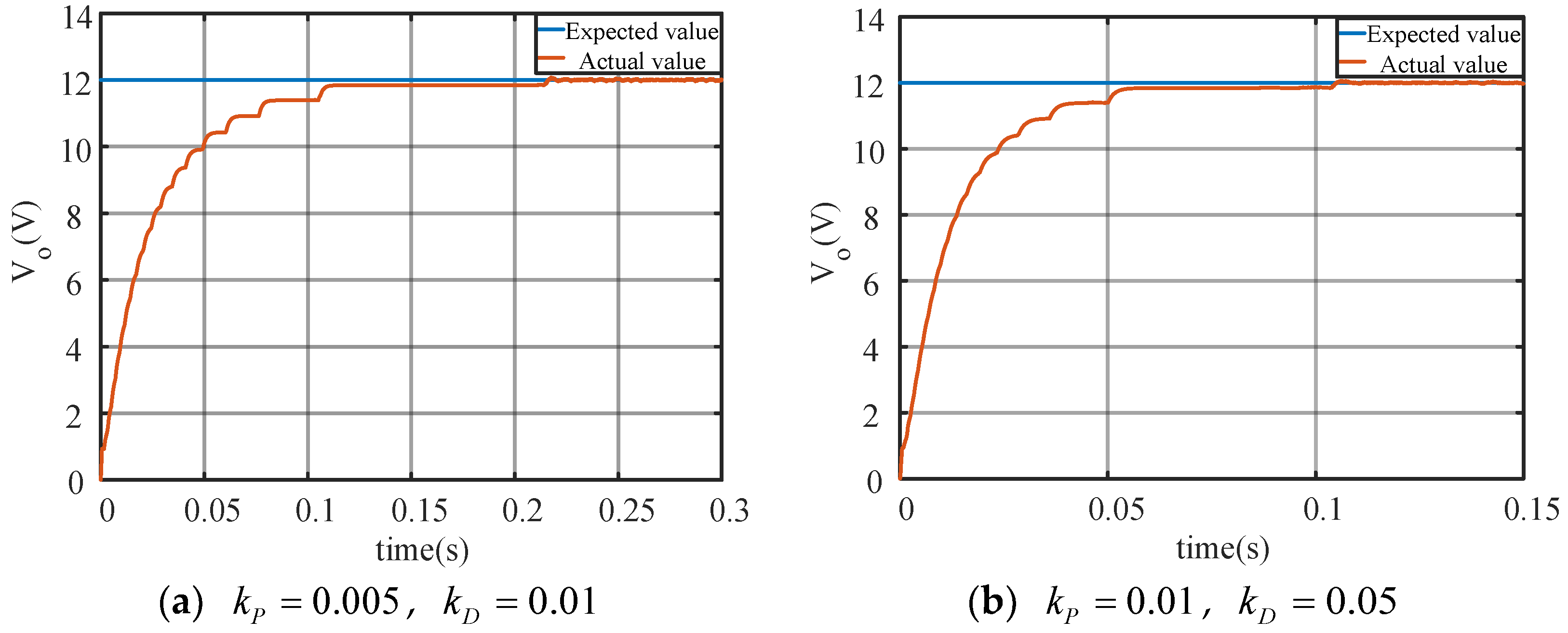
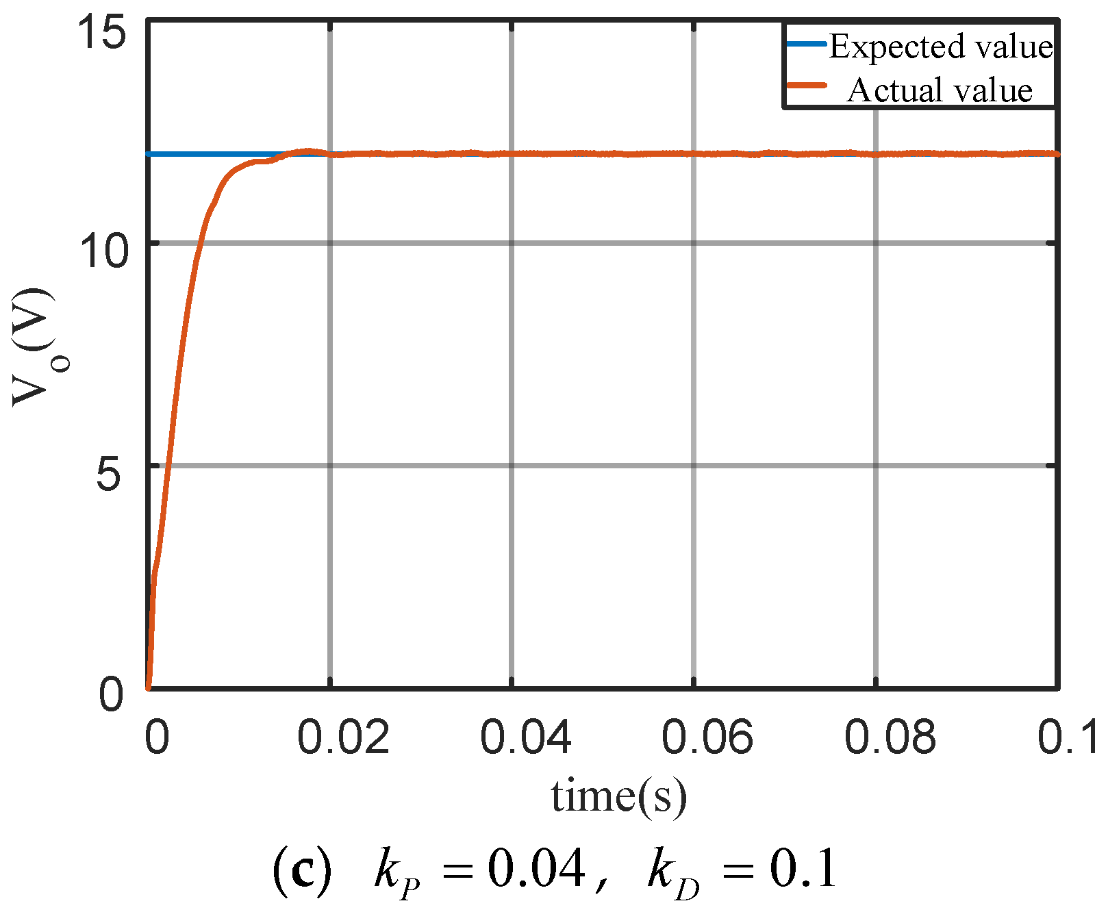
In this section, we will be verifying the effectiveness and superiority of the proposed ILC for a buck DC/DC power converter. We have simulated and analyzed using Matlab2020a/Simulink (PC, i5, DualCore, 8 Gb RAM). The iterative controller parameters used in the simulation are as follows: k P = 0.05 and k D = 0.1 , and the expected simulation result of 12 V is shown in Figure 12.
Three sets of different parameters, iteration +pi simulation:
In order to verify the effectiveness and superiority of iterative learning control in the control of the DC/DC power converter, this paper uses Matlab/Simulink to simulate the buck power converter, and the expected output voltage in the simulation is 12 V. The simulation results of open-loop PD iterative learning control are shown in Figure 12. It can be seen from the figure that with the gradual increase in the parameters, the rise time of the system becomes smaller and smaller, and the system has no overshoot. After the parameters are well adjusted, the system has better dynamic and steady performance.
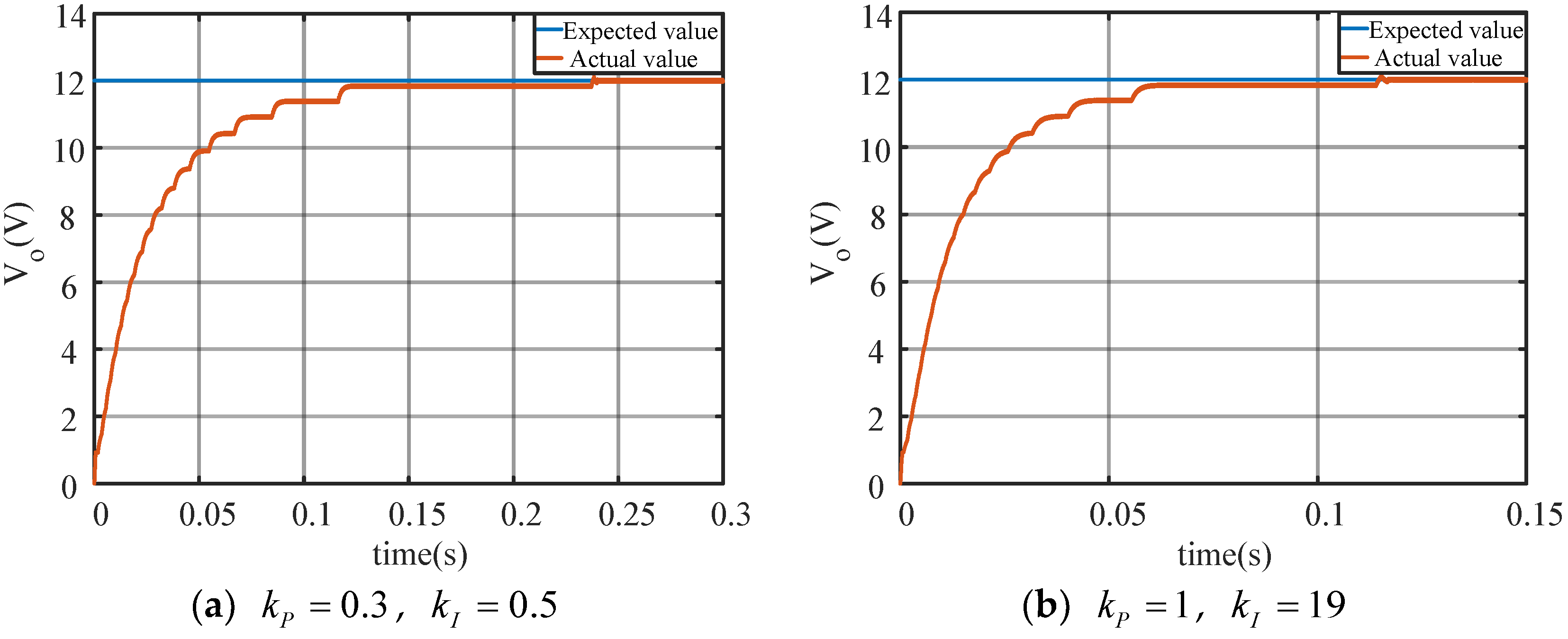
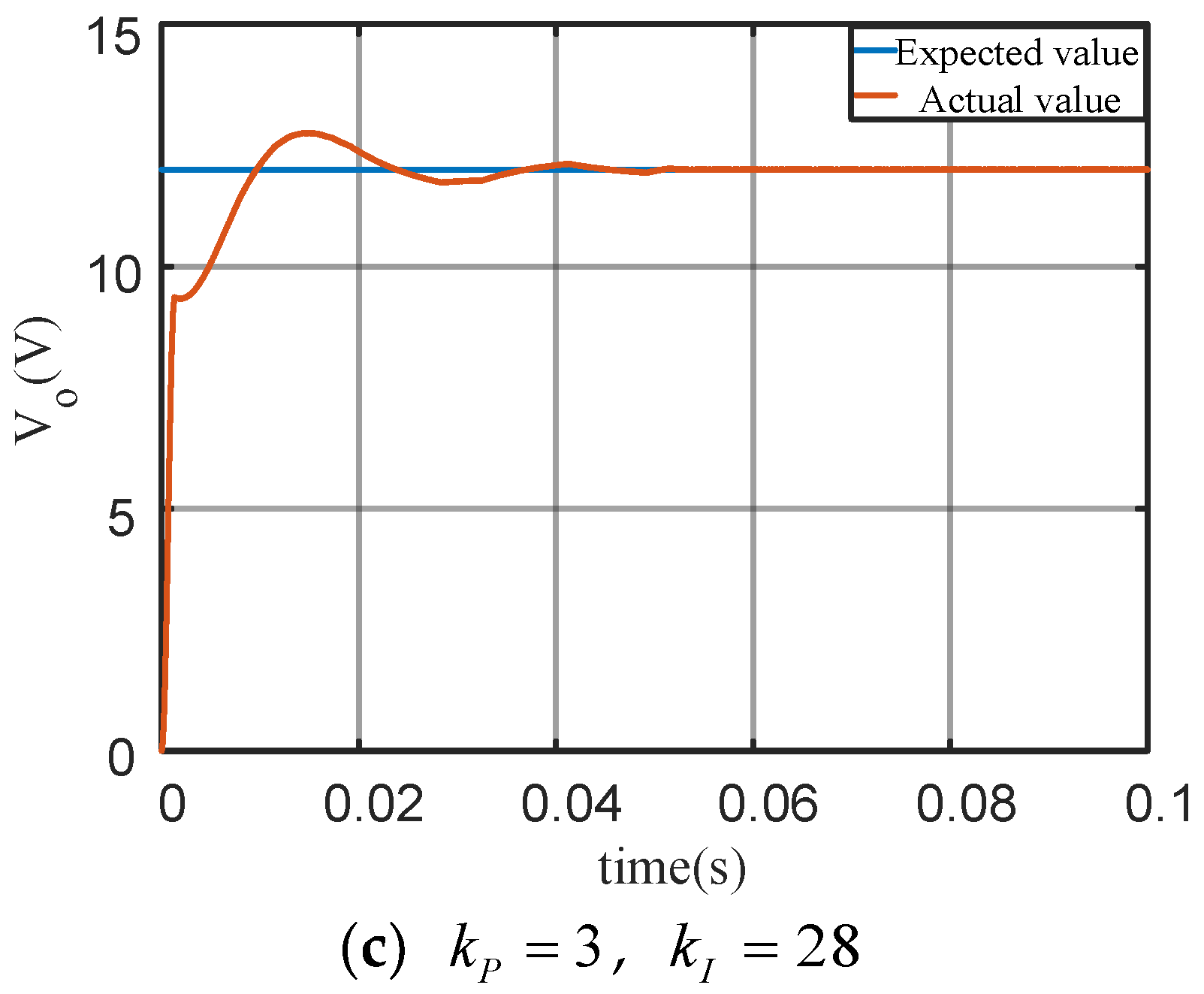
For the simulation purpose, we can describe the parameters of the PI controller that are used: k P = 30 , k I = 2000 , and the expected simulation result of 12 V is shown in Figure 13. For a comparative analysis with iterative learning control, we present the simulation results of the conventional positional PI control in the following sections. From Figure 13, it is evident that as the parameters increase, the system’s rise time decreases. However, if the parameters become excessively large, the system will experience overshoot. Therefore, the traditional positional PI needs to take intermediate parameters in practical applications, which makes it difficult to ensure the dynamic and steady performance of the system simultaneously.
From Figure 12 to Figure 13, compared with the traditional PID control, the iterative learning control has no overshoot and the rise time is smaller.

5.2. Experimental Results

According to the basic principles described in Section 3, open-loop PD-type ILC and PI control, we have carried out experimental verification for a buck converter. The main experimental results are depicted and analyzed in Figure 14 and Figure 15.
It is obvious that the results show the fixed value tracking performance of ILC, which is far improved compared to the traditional positional PI control, as shown in Figure 14. In order to ensure dynamic and steady-state performance simultaneously, the traditional positional PI control needs to compromise parameters, which makes it difficult to obtain the optimal matching effect, and the parameter adjustment is more problematic. The iterative learning control can solve this problem very effectively, as the results in Figure 15 show. The ILC control method only needs to adjust the parameters gradually under the condition of ensuring system convergence so that system performance can be optimized, and its parameter adjustment is simple.

6. Conclusions

In this research, we have experimentally verified the iterative learning control to control the DC/DC power buck converter in order to solve the difficulties of traditional PI and PID control. The main key findings are as follows:
  • We have proposed a new scheme that switches the buck DC/DC converter into a switching system that further consists of two different states of on and off, and we used the switching period average operator and the state space average method to equivalent a linear time-varying continuous circuit. This law is determined by the duty cycle of the switch tube control signal.
  • We have successfully controlled the system with an open-loop PD-type ILC. Additionally, we have used the ILC to control the buck DC/DC converter, and our results have been compared to typical PI control.
  • We have proven that the traditional PI-type buck converter control method is effective and compared the both control effects. We have evaluated, in simulation and experimental results, that the ILC has obvious advantages compared with typical PI control.
It is obvious that traditional PI control has complexity in parameter adjustment and poor control effects on the nonlinear, time-varying response, and this is a challenging task for such systems. The feasibility and superiority of iterative learning control are verified through simulation and then further proven through experiments. We have compared the experimental results of our proposed control with the traditional PI controller. Our experimental results verified that the buck converter can be controlled more precisely using ILC instead of the traditional PI control. Finally, we experimentally verified that ILC also has the advantages of simple parameter adjustments and easy implementation. We can implement the PD-type ILC for DC/DC boost converters as well as for other renewable energy control systems in future.

Author Contributions

Conceptualization, S.R. and B.L.; methodology, S.R.; software, S.R.; validation, Y.Z., S.R. and B.L.; formal analysis, Y.Z.; investigation, B.L.; resources, Y.Z.; data curation, B.L.; writing—original draft preparation, S.R.; writing—review and editing, B.L. and Y.Z.; visualization, B.L.; supervision, S.R. and B.L.; project administration, B.L.; funding acquisition, B.L. All authors have read and agreed to the published version of the manuscript.

Funding

This research has been funded by the following agencies: (1) the Shaanxi Provincial Science Fund for Distinguished Young Scholars (2022JC-32) and (2) the Joint Key Project of Shaanxi Key R&D Program: 2021GXLH-01-14.

Data Availability Statement

All the data are included within the article. They can be provided on demand from the corresponding author.

Conflicts of Interest

The funders had no role in the design of the study; in the collection, analyses, or interpretation of data; in the writing of the manuscript; or in the decision to publish the results.

References

  1. Wei, F.; Bojin, Q.; Yipeng, W.; Haolin, L. High power DC-DC converter for renewable energy power system. In Proceedings of the 2014 IEEE Conference and Expo Transportation Electrification Asia-Pacific (ITEC Asia-Pacific), Beijing, China, 31 August–3 September 2014; pp. 1–4. [Google Scholar] [CrossRef]
  2. Rasin, Z.; Rahman, M.F. Control of bidirectional DC-DC converter for battery storage system in grid-connected quasi-Z-source pv inverter. In Proceedings of the 2015 IEEE Conference on Energy Conversion (CENCON), Johor Bahru, Malaysia, 19–20 October 2015; pp. 205–210. [Google Scholar] [CrossRef]
  3. Matsumori, H.; Kosaka, T.; Sekido, K.; Kim, K.; Egawa, T.; Matsui, N. Isolated DC-DC Converter utilizing GaN power device for Automotive Application. In Proceedings of the 2019 IEEE Applied Power Electronics Conference and Exposition (APEC), Anaheim, CA, USA, 17–21 March 2019; pp. 1704–1709. [Google Scholar] [CrossRef]
  4. Ning, J.; Zeng, J.; Du, X. A Four-port Bidirectional DC-DC Converter for Renewable Energy-Battery-DC Microgrid System. In Proceedings of the 2019 IEEE Energy Conversion Congress and Exposition (ECCE), Baltimore, MD, USA, 29 September–3 October 2019; pp. 6722–6727. [Google Scholar] [CrossRef]
  5. Liu, H.; Liu, K.; Sun, B. Analysis of energy management strategy for energy-storage type elevator based on supercapacitor. In Proceedings of the 2017 11th IEEE International Conference on Compatibility, Power Electronics and Power Engineering (CPE-POWERENG), Cadiz, Spain, 4–6 April 2017; pp. 175–180. [Google Scholar] [CrossRef]
  6. Yi, Z.; Chen, Z.; Yin, K.; Wang, L.; Wang, K. Sensing as the key to the safety and sustainability of new energy storage devices. Prot. Control Mod. Power Syst. 2023, 8, 27. [Google Scholar] [CrossRef]
  7. Zhang, M.; Yang, D.; Du, J.; Sun, H.; Li, L.; Wang, L.; Wang, K. A review of SOH prediction of Li-ion batteries based on data-driven algorithms. Energies 2023, 16, 3167. [Google Scholar] [CrossRef]
  8. Wang, X.; Wu, M.; Ouyang, L.; Tang, Q. The application of GA-PID control algorithm to DC-DC converter. In Proceedings of the 29th Chinese Control Conference, Beijing, China, 29–31 July 2010; pp. 3492–3496. [Google Scholar]
  9. Hongmei, L.; Xiao, Y. Sliding-mode PID control of DC-DC converter. In Proceedings of the 2010 5th IEEE Conference on Industrial Electronics and Applications, Taichung, Taiwan, 15–17 June 2010; pp. 730–734. [Google Scholar] [CrossRef]
  10. Guo, Y.; Zhang, C.; Wang, Z.; Huang, L. Study on the method of fuzzy PID control for DC/DC converter. In Proceedings of the 2010 International Conference on Information, Networking and Automation (ICINA), Kunming, China, 18–19 October 2010; pp. V1–329–V1–332. [Google Scholar] [CrossRef]
  11. Puchta, E.D.P.; Lucas, R.; Ferreira, F.R.V.; Siqueira, H.V.; Kaster, M.S. Gaussian adaptive PID control optimized via genetic algorithm applied to a step-down DC-DC converter. In Proceedings of the 2016 12th IEEE International Conference on Industry Applications (INDUSCON), Curitiba, Brazil, 20–23 November 2016; pp. 1–6. [Google Scholar] [CrossRef]
  12. Malik, P.S.; Gawas, S.S.; Patel, I.A.; Parsekar, N.P.; Parab, A.A.; Parkar, S.S. Transient Response Improvement of DC to DC Converter by Using Auto-tuned PID Controller. In Proceedings of the 2018 Second International Conference on Inventive Communication and Computational Technologies (ICICCT), Coimbatore, India, 20–21 April 2018; pp. 546–549. [Google Scholar] [CrossRef]
  13. Zayed, M.E.; Zhao, J.; Li, W.; Elsheikh, A.H.; Abd Elaziz, M.; Yousri, D.; Zhong, S.; Mingxi, Z. Predicting the performance of solar dish Stirling power plant using a hybrid random vector functional link/chimp optimization model. Sol. Energy 2021, 222, 1–17. [Google Scholar] [CrossRef]
  14. Zayed, M.E.; Zhao, J.; Elsheikh, A.H.; Li, W.; Sadek, S.; Aboelmaaref, M.M. A comprehensive review on Dish/Stirling concentrated solar power systems: Design, optical and geometrical analyses, thermal performance assessment, and applications. J. Clean. Prod. 2021, 283, 124664. [Google Scholar] [CrossRef]
  15. Rezk, H.; Mazen, A.-O.; Gomaa, M.R.; Tolba, M.A.; Fathy, A.; Abdelkareem, M.A.; Olabi, A.; Abou Hashema, M. A novel statistical performance evaluation of most modern optimization-based global MPPT techniques for partially shaded PV system. Renew. Sustain. Energy Rev. 2019, 115, 109372. [Google Scholar] [CrossRef]
  16. Rezk, H.; Arfaoui, J.; Gomaa, M.R. Optimal parameter estimation of solar PV panel based on hybrid particle swarm and grey wolf optimization algorithms. Int. J. Interact. Multimed. Artif. Intell. 2021, 6, 145–155. [Google Scholar] [CrossRef]
  17. Bao, H.; Shu, P.; Wang, Q. Accurate visual representation learning for single object tracking. Multimed. Tools Appl. 2022, 81, 24059–24079. [Google Scholar] [CrossRef]
  18. Wang, X.; Wang, Y.; Tang, L.; Zhang, Q. Multi-Objective Ensemble Learning with Multi-Scale Data for Product Quality Prediction in Iron and Steel Industry. IEEE Trans. Evol. Comput. 2023. [Google Scholar] [CrossRef]
  19. Storey, E.E.; Helmy, A.S. Optimized preprocessing and machine learning for quantitative Raman spectroscopy in biology. J. Raman Spectrosc. 2019, 50, 958–968. [Google Scholar] [CrossRef]
  20. Ma, N.; Yin, H.; Wang, K. Prediction of the Remaining Useful Life of Supercapacitors at Different Temperatures Based on Improved Long Short-Term Memory. Energies 2023, 16, 5240. [Google Scholar] [CrossRef]
  21. Sun, X.; Zhang, Y.; Zhang, Y.; Wang, L.; Wang, K. Summary of Health-State Estimation of Lithium-Ion Batteries Based on Electrochemical Impedance Spectroscopy. Energies 2023, 16, 5682. [Google Scholar] [CrossRef]
  22. Hoehler, D.; Haag, J.; Kozlov, A.M.; Stamatakis, A. A representative performance assessment of maximum likelihood based phylogenetic inference tools. bioRxiv 2022. [Google Scholar] [CrossRef]
  23. Tsypkin, Y.Z. Robust Control Systems with Internal Nominal Models. In Control of Uncertain Dynamic Systems; CRC Press: Boca Raton, FL, USA, 2020; pp. 501–509. [Google Scholar]
  24. Tsypkin, Y.Z.; Polyak, B. Frequency domain criterion for robust stability of polytope of polynomials. In Control of Uncertain Dynamic Systems; CRC Press: Boca Raton, FL, USA, 2020; pp. 491–499. [Google Scholar]
  25. Arimoto, S.; Kawamura, S.; Miyazaki, F. Bettering operation of Robots by learning. J. Robot. Syst. 2007, 1, 123–140. [Google Scholar] [CrossRef]
  26. Li, G. High-order iterative learning control for nonlinear systems. In Proceedings of the 2017 6th Data Driven Control and Learning Systems (DDCLS), Chongqing, China, 26–27 May 2017; pp. 191–196. [Google Scholar] [CrossRef]
  27. Zhang, R.; Hou, Z.; Chi, R.; Li, Z. Data-driven iterative learning control for I/O constrained LTI systems. In Proceedings of the 2016 35th Chinese Control Conference (CCC), Chengdu, China, 27–29 July 2016; pp. 3166–3171. [Google Scholar] [CrossRef]
  28. Jingli, K. Iterative learning control algorithm based on Chebyshev orthonormal basis for nonlinear systems. In Proceedings of the 2015 34th Chinese Control Conference (CCC), Hangzhou, China, 28–30 July 2015; pp. 3017–3021. [Google Scholar] [CrossRef]
  29. Shan-hai, X.; Zhong, Z.; Xin, Z. PD-type open-closed-loop iterative learning control in the networked control system. In Proceedings of the 2016 Chinese Control and Decision Conference (CCDC), Yinchuan, China, 28–30 May 2016; pp. 5738–5744. [Google Scholar] [CrossRef]
  30. Ruikun, Z.; Ronghu, C. Iterative learning control for a class of MIMO nonlinear system with input saturation constraint. In Proceedings of the 2017 36th Chinese Control Conference (CCC), Dalian, China, 26–28 July 2017; pp. 3543–3547. [Google Scholar] [CrossRef]
  31. Riaz, S.; Lin, H.; Waqas, M.; Afzal, F.; Wang, K.; Saeed, N. An accelerated error convergence design criterion and implementation of lebesgue-p norm ILC control topology for linear position control systems. Math. Probl. Eng. 2021, 2021, 5975158. [Google Scholar] [CrossRef]
  32. Xining, Z.; Chenglin, L.; Fei, L. A class of P-type fuzzy iterative learning control design. In Proceedings of the 31st Chinese Control Conference, Hefei, China, 25–27 July 2012; pp. 3052–3056. [Google Scholar]
  33. Riaz, S.; Lin, H.; Akhter, M.P. Design and implementation of an accelerated error convergence criterion for norm optimal iterative learning controller. Electronics 2020, 9, 1766. [Google Scholar] [CrossRef]
  34. Yan, Q.; Cai, J.; Wu, L.; Zhou, Q. Error-Tracking Iterative Learning Control for Nonlinearly Parametric Time-Delay Systems with Initial State Errors. IEEE Access 2018, 6, 12167–12174. [Google Scholar] [CrossRef]
  35. Dai, X.; Tian, S.; Peng, Y.; Luo, W. Closed-loop P-type iterative learning control of uncertain linear distributed parameter systems. IEEE/CAA J. Autom. Sin. 2014, 1, 267–273. [Google Scholar] [CrossRef]
  36. Yan, Q.; Cai, J.; Yu, Y. Suboptimal learning control for nonlinear dynamic systems. In Proceedings of the 2017 Chinese Automation Congress (CAC), Jinan, China, 20–22 October 2017. [Google Scholar]
  37. Wang, J.; Wang, Y.; Wang, W.; Cao, L.; Jin, Q. Adaptive iterative learning control based on unfalsified strategy applied in batch process. J. Cent. South Univ. 2015, 46, 1318–1325. [Google Scholar]
  38. Zhang, X.; Wang, B.; Gamage, D.; Ukil, A. Model predictive and iterative learning control based hybrid control method for hybrid energy storage system. IEEE Trans. Sustain. Energy 2021, 12, 2146–2158. [Google Scholar] [CrossRef]
  39. Wang, X.; Luo, Y.; Qin, B.; Guo, L. Power dynamic allocation strategy for urban rail hybrid energy storage system based on iterative learning control. Energy 2022, 245, 123263. [Google Scholar] [CrossRef]
  40. Angalaeswari, S.; Jamuna, K. Design and implementation of a robust iterative learning controller for voltage and frequency stabilization of hybrid microgrids. Comput. Electr. Eng. 2020, 84, 106631. [Google Scholar] [CrossRef]
  41. Özbek, N.S.; Çelik, Ö. Design and analysis of a novel adaptive learning control scheme for performance promotion of grid-connected PV systems. Sustain. Energy Technol. Assess. 2022, 52, 102045. [Google Scholar] [CrossRef]
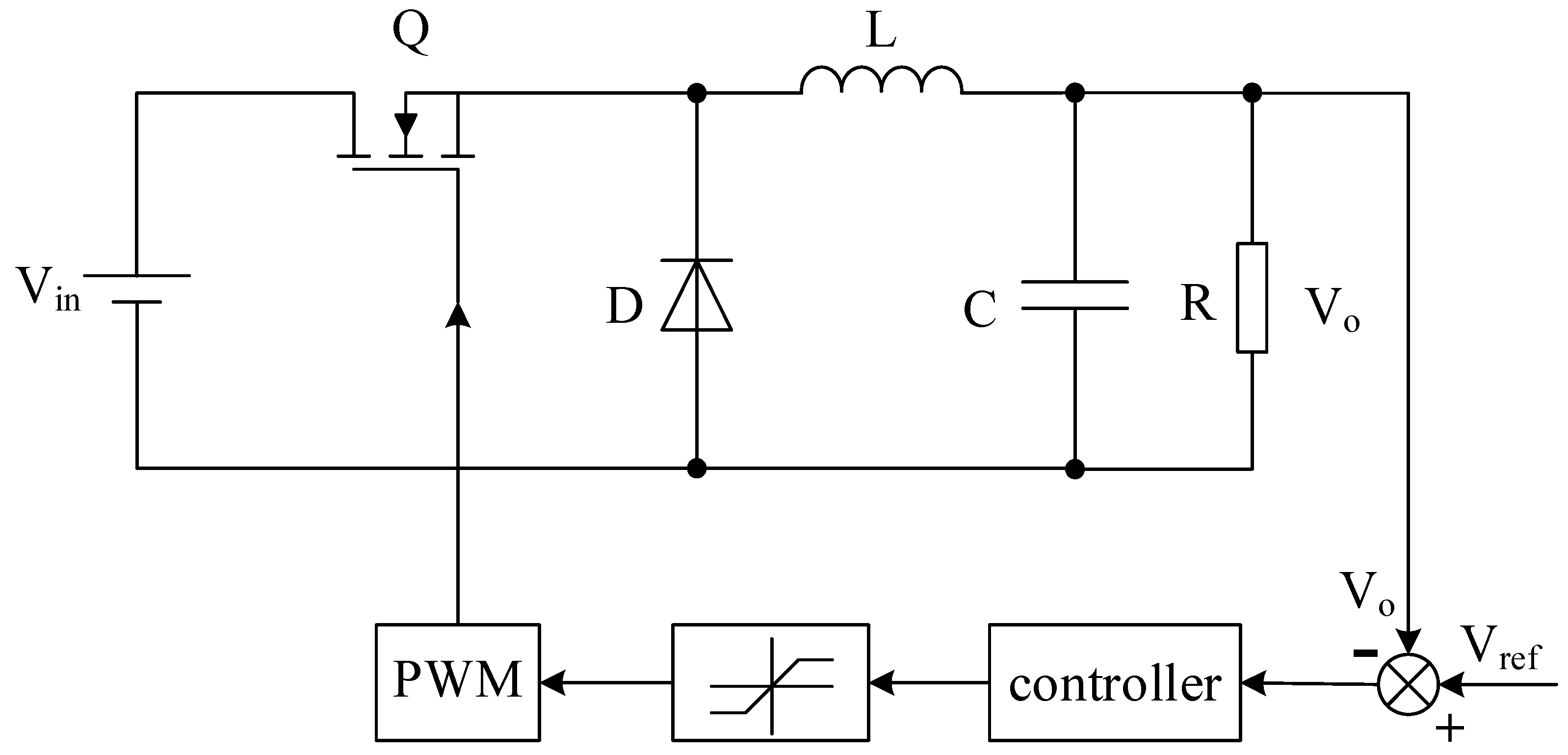
Figure 1. Basic diagram of traditional control of buck converter.
Energies 16 06555 g001
Figure 2. Equivalent circuit of buck converter under different switching states. (a) Description of the switch Q is turned on. (b) Description of the switch Q is turned off.
Energies 16 06555 g002
Figure 3. The equivalent AC model of buck converter.
Energies 16 06555 g003
Figure 4. Buck converter open-loop transfer function bode diagram.
Energies 16 06555 g004
Figure 5. The corrected buck converter open-loop transfer function bode diagram.
Energies 16 06555 g005
Figure 6. Expected trajectory tracking diagram of switching system.
Energies 16 06555 g006
Figure 7. Basic block diagram of open-loop iterative learning.
Energies 16 06555 g007
Figure 8. (a) Implementation block diagram of open-loop iterative learning control. (b) Overall block diagram of proposed control.
Energies 16 06555 g008
Figure 9. Buck converter structure block diagram.
Energies 16 06555 g009
Figure 10. Buck converter physical setup representation (a) Input/Output interface (b) physical drive power circuit.
Energies 16 06555 g010
Figure 11. Schematic diagram of open-loop ILC calculation.
Energies 16 06555 g011
Figure 12. Buck converter iterative learning control simulation results.
Energies 16 06555 g012aEnergies 16 06555 g012b
Figure 13. Buck converter PI control simulation results.
Energies 16 06555 g013aEnergies 16 06555 g013b
Figure 14. Buck converter iterative learning control experiment results.
Energies 16 06555 g014
Figure 15. Experimental results of positional PI control of buck converter.
Energies 16 06555 g015
Disclaimer/Publisher’s Note: The statements, opinions and data contained in all publications are solely those of the individual author(s) and contributor(s) and not of MDPI and/or the editor(s). MDPI and/or the editor(s) disclaim responsibility for any injury to people or property resulting from any ideas, methods, instructions or products referred to in the content.