Article

Techno-Economic Analysis of Hydrogen Production from Swine Manure Biogas via Steam Reforming in Pilot-Scale Installation

by
Artur Wodołażski
1,
Małgorzata Magdziarczyk
2 and
Adam Smoliński
3,4,*
1
Department of Energy Saving and Air Protection, Central Mining Institute, Plac Gwarkow 1, 40-166 Katowice, Poland
2
Department of Economics, Finance, Regional and International Research, Opole University of Technology, Luboszycka 7, 45-036 Opole, Poland
3
Central Mining Institute, Plac Gwarkow 1, 40-166 Katowice, Poland
4
Spolka Restrukturyzacji Kopaln S.A., Strzelców Bytomskich 207, 41-914 Bytom, Poland
*
Author to whom correspondence should be addressed.
Energies 2023, 16(17), 6389; https://doi.org/10.3390/en16176389
Submission received: 7 August 2023 / Revised: 20 August 2023 / Accepted: 1 September 2023 / Published: 3 September 2023
(This article belongs to the Section C: Energy Economics and Policy)

Abstract

:
The main purpose of this paper is the techno-economic analysis of hydrogen production from biogas via steam reforming in a pilot plant. Process flow modeling based on mass and energy balance is used to estimate the total equipment purchase and operating costs of hydrogen production. The pilot plant installation produced 250.67 kg/h hydrogen from 1260 kg/h biomethane obtained after purification of 4208 m3/h biogas using a heat and mass integration process. Despite the high investment cost, the plant shows a great potential for biomethane reduction and conversion to hydrogen, an attractive economic path with ecological possibilities. The conversion of waste into hydrogen is a possibility of increasing importance in the global energy economy. In the future, such a plant will be expanded with a CO2 reduction module to increase economic efficiency and further reduce greenhouse gases in an economically viable manner.

1. Introduction

With the continued development of civilization, the demand for energy increases. It is widely believed that traditional energy resources, mainly fossil fuels (coal, oil, natural gas), are becoming scarce and that their consumption causes an increase in environmental pollution, mainly in the form of greenhouse gases [1,2,3]. Municipal waste treatment is one of the main environmental problems, especially in developing countries, where the generation of municipal solid waste is four time higher than that noted in the last three decades [3]. Biogas can be an alternative feedstock to conventional steam reforming technology because it is a renewable resource, reduces emissions by preventing the release of methane into the atmosphere, and is used commercially and produced in large quantities in anaerobic digesters and landfills.
Therefore, new technologies that convert waste into energy carriers, with a simultaneous reduction in the emission of greenhouse gases into the atmosphere, seem to be very attractive [4,5]. In EU countries, energy issues are regulated by relevant directives, the so-called green and white papers [6]. The potential biogas available in the EU significantly exceeds the consumption of methane, and relevant laws and regulations promote an increasing share of biomass products as energy carriers. EU countries are dependent on agriculture and produce large amounts of manure, which contributes significantly to the greenhouse effect. The gases emitted in this process are composed of various pathogens. The development of the waste utilization technologies and convert it into environmentally friendly energy carriers is highly desirable [7]. The chemical composition of biogas depends not only on the technology of the methanation processes, but also on the type of raw materials and process conditions used [8]. The selection of the optimal feedstock and process conditions is widely presented in the literature [9]. The crucial research activities are oriented towards the development of effective technologies that will help determine not only the composition of the raw materials and process parameters, but also the economic efficiency of the entire process [10,11,12]. The hydrogen production by the steam reforming of methane is responsible for about 68% of the worldwide hydrogen production [13,14]. Biogas to biohydrogen technological plants can be fed with manure, agricultural waste, or waste from the agro-food industries. In addition, the biogas conversion to hydrogen as an new, environmentally friendly energy carrier, could be used to produce electricity. For example, 500 kW of electricity can be obtained from the fermentation of 15 Mg of biomass per day. Bruno [15] employed the integration of absorption cooling systems into a micro gas turbine using biogas from a sewage treatment plant. Peerapong and Limmeechokchai [16] designed and built a plant to convert biogas into hydrogen on a pig farm in Thailand. Putmai and Xiao [17,18] conducted studies to increase biogas production from the anaerobic digestion of manure using granulated activated carbon. It allows for the production of more sustainable and economical fuel through the use of renewable sources. The authors present evaluations of biogas composition for optimal operating conditions. Soares [19] studied the production of biogas from manure in an economic recirculation system. An important issue is the energy and material integration of the plant, as well as the consideration of the technological performance indicators that allow for increasing the energy efficiency of each technological node. Replacing natural gas with biogas in methane steam reforming technology significantly contributes to the overall reduction of the CO2 impact on the greenhouse effect, multiplied by the reduction of methane emissions [20]. Braga et al. [21] presents a hydrogen production method using biogas steam reforming technology with a technical analysis using Gibbs energy equilibrium reactor model. However, the article does not present the scale effect and influence of individual process parameters (temperature, pressure, methane/water ratio) on the degree of methane conversion and hydrogen production. Chouhan et. al. [22] simulate the steam reforming of biogas in an industrial reformer for hydrogen production. A model of an industrial-scale catalytic packed bed reactor has been developed to calculate the effect of changes in temperature, pressure, and heat of reaction along the entire reactor length on some physical properties, including dynamic viscosity, gas mixture density, and heat of reaction. A thermodynamic equilibrium analysis has also been provided to consider the influencing parameters for adjusting operating conditions. However, the above mentioned articles do not present the technical and economic costs inherent in the relationship between the operating conditions of the process and the equipment used. The gap in the literature regarding this dependency encourages more detailed analyses of numerical modeling.
In this work, a pilot plant has been designed and modeled to process 1260 kg/h of biomethane obtained after purification from 4258 kg/h of biogas. The model takes into account the composition of the biogas, which examines the effect of heat and electricity prices on the profitability of the plant. The thermodynamic performance of SRM (steam methane reforming) and WGS (water–gas shift reaction), based on mass and energy balance, is evaluated using energy and exergy analysis. The data required to perform this study in a simulation model is implemented in CHEMCAD. The calculation results regarding pilot-scale hydrogen production will be used in the future in the technical feasibility study for the technical, ecological, and economic analysis of the development of the plant. This is an indication of a future project for investors who want to consider a new technological approach to the processing of waste into hydrogen while reducing the harmful effects of greenhouse gases, such as methane.

2. Materials and Methods

The conceptual design of a plant for the purification of biogas from manure to produce hydrogen in a large-scale process is implemented in CHEMCAD. Process design and simulation allow for mass and energy analysis, along with cost estimation, for potential investors aiming to process biomethane to hydrogen, reducing the greenhouse effect associated with its harmful effects on the environment.
The following model assumptions were considered for the calculation of the mass and energy balance:
-
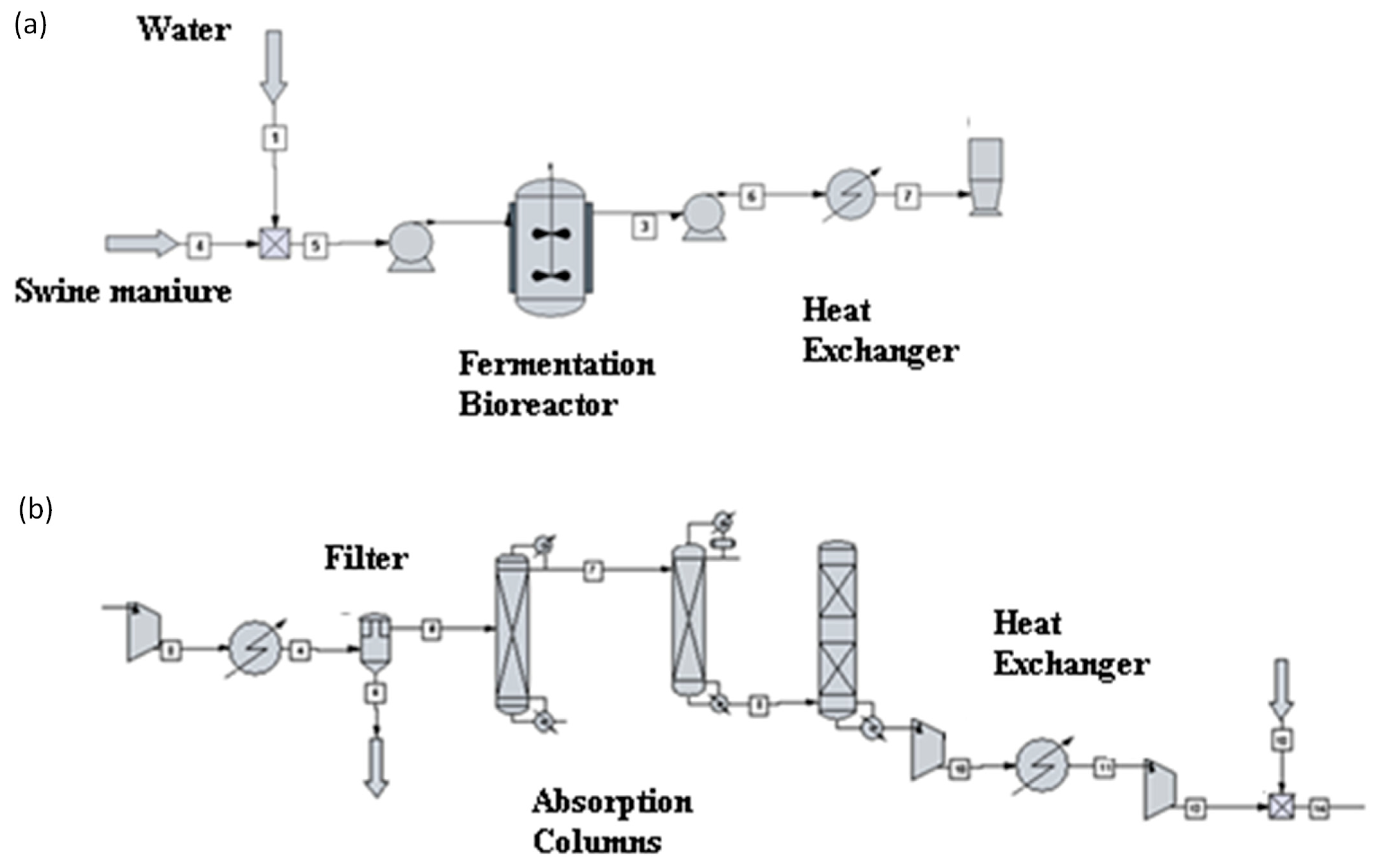
It is assumed that 1 pig produces 2.3 kg/day of manure, and the farm consists of 13,050 pigs.
-
The basic composition of the biogas in the simulation is 61.3% methane, 26.78% CO2, and 11.92% H2S.
-
The steam generator has an air excess of 30%, with an energy efficiency of 86%.
-
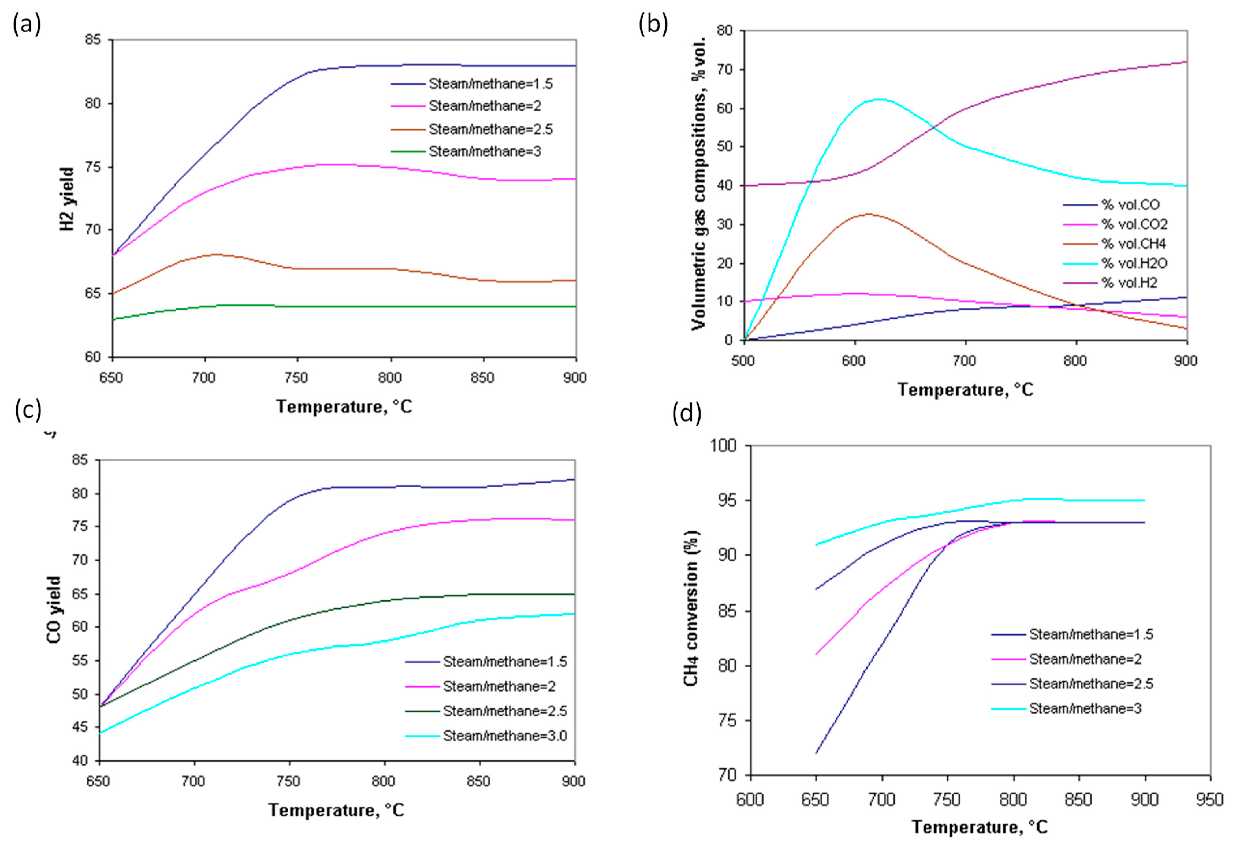
The reformer reactor operates at a temperature of 700 °C, under the following conditions: a steam to methane ratio of 3:1, and a pressure of 105 kPa.
-
The water–gas shift reactor operates at a temperature of 350 °C, and a pressure of 4 MPa.
The process of methane steam conversion (1) is a highly endothermic reaction, and its equilibrium shifts to the right with increasing temperature. Since it proceeds with an increase in volume, an increase in pressure adversely affects the position of the equilibrium state. On the other hand, the conversion reaction of carbon monoxide with water vapor (2) is highly exothermic, and its equilibrium shifts to the left with increasing temperature. At the same time, excess water vapor increases the formation of carbon dioxide.
H 2 O + C H 4 3 H 2 + C O Δ H = 206   k J / m o l
H 2 O + C O H 2 + C O 2 Δ H = 42   k J / m o l
The appropriate thermodynamics Soave–Redlich–Kwong (SRK) property method was used to be able to predict both the immiscible liquid and the separation phase. The non-random two-liquid (NRTL) model was found to be more suitable to describe the vapor–liquid equilibrium of a non-ideal system for reactor to hydrogen production. The NRTL model was used to evaluate the gas–liquid separator, and the SRK model was selected for all other unit operations.
Figure 1 shows a diagram of biogas purification to biomethane concentration. The technology used in biogas treatment is economically effective and is based on CO2 absorption by high-pressure water scrubbing and H2S removal on an activated carbon bed. In the absorption unit, CO2 is absorbed in the circulating wash water stream. The efficiency of coal desulfurization is 99.89%. In the absorption unit, CO2 is absorbed in the circulating wash water stream. Biogas, compressed to a pressure of 1.7 MPa, is subjected to water washing in the absorption column. After pressure reduction in the desorption column, CO2 is removed, and the water is recycled. The treatment capacity of the plant is 4200 m3/h. The driving force in the biogas treatment process is the difference in solubility of CO2 and ethanol in water, especially at elevated pressures. The ratio of feed water flow to CO2 gas flow in the feed water of the absorption column is an important parameter for the absorption efficiency. Figure 1. shows an installation diagram for the conversion of biomethane to hydrogen by methane steam reforming and water–gas reaction. CHEMCAD software was used for process modeling. Methane steam reforming is carried out at a high temperature of 900 °C and a pressure of 3 MPa on an Ni and Al2O3 catalyst support. Biomethane is mixed with steam in a ratio of 2–4:1, and the heat of the reaction products is used to heat the dosed substrates. A level of 20% excess air is used in the steam generator. The water–gas reactor operates at a temperature of 350 °C and a pressure of 2–3 MPa. A kinetic reactor is used, in which individual kinetic data from the reactor have been taken from references [3,6,9]. It was assumed that before starting the operation of the reaction node, the biogas from the fermentation process was pre-dried, dusted on cyclones from the solid fraction, and purified from hydrogen sulfide and carbon dioxide on absorption columns with a solution of N-methyldiethanolamine (MDEA) and Selexol solvent (a mixture of polyethylene glycol and dimethyl ether). Process balancing was carried out using the physicochemical and thermodynamic parameters of chemical substances affecting the streams analyzed. The SRK model (Soave–Redlich–Kwong) was used to determine the values of the equilibrium constants and the enthalpy. The simulation of the system was carried out using process data taken from the literature studies [6,7]. The reactor uses tubes with an inner diameter of 90 mm and a wall thickness of 17 mm to maintain the appropriate high temperature in the middle catalyst layer. The volume of the SMR is 37.82 m3, while the volume of the water–gas shift reactor is 23.82 m3. The definition of the main chemical components was taken from software database. Software databases infer the behavior of the liquid and vapor phase of substance involved in the thermodynamic model for vapor–liquid equilibria and global yields to evaluate their performance. The biogas composition came from swine manure subjected to thermophilic conditions (55 °C for 21 days). For steam reforming, a thermodynamic and kinetics reactor was employed. The C++ script, implemented in CHEMCAD software, is used to implement the reaction kinetics model [23] of steam reforming. The following is a detailed description of the modeling conditions.
Figure 2 shows a process flow diagram of biomethane to hydrogen conversion. The steam and methane flows to the mixer, and mixture then flows to the methane steam reformer reactor, where the products and substrates are heated. The syngas next enters the water–gas shift reactor. Methane steam reforming is carried out at the high temperature of 900 °C and a pressure of 3 MPa on an Ni catalyst with Al2O3 support. Biomethane is mixed with steam in the ratio of 2,3,4:1, and the heat of the reaction products is used to heat the dosed substrates. An amount of 30% excess air is used in the steam generator. The water–gas reactor operates at a temperature of 350 °C and a pressure of 2–3 MPa. A kinetic reactor is used, in which the individual kinetic data of the reactor have been taken from reference [8].
The energy efficiency is calculated according to Formula (3):
η = n ˙ H 2 L H V H 2 n ˙ B i o g a s F u e l L H V B i o g a s F u e l + n ˙ B i o g a s Re f L H V B i o g a s Re f
where η denotes energy efficiency, n ˙ H 2 denotes hydrogen flow rate H2 (kg/s), n ˙ B i o g a s F u e l denotes biogas steam flow rate (kg/s), n ˙ B i o g a s Re f denotes reformer products flow rate, and L H V H 2 , L H V B i o g a s F u e l , and L H V B i o g a s Re f denote low calorific value.
The chemical exergy in the flow is calculated from Formula [6]:
E χ C H = V 0 i = 1 n γ 0 , i E χ C H , i 0 v + L 0 i = 1 n χ 0 , i E χ C H , i 0 L
where E χ C H denotes specific chemical flow exergy i (kJ/kg), E χ C H 0 L denotes standard chemical flow exergy in the liquid phase (kJ/kg), and E χ C H 0 v denotes standard chemical flow exergy in the vapor phase (kJ/kg).
The physical exergy of the flow is calculated from Equation (5):
E χ P H = ( h h 0 ) T 0 ( s s 0 )
where h, h0 denote specific enthalpy (kJ/kg) and specific enthalpy at standard state (kJ/kg); s , s 0 denote entropy and entropy at the standard state (kJ/kg·°C); and T 0 denotes temperature at the standard state (°C). The total exergy is calculated by the sum of physical ( E χ P H ) and chemical exergy ( E χ C H ).
The cost of production is calculated using Formula (6):
C H 2 = C M A N + f I H n ˙ H 2 + C O P
where: C H 2 —hydrogen production costs (US$/kWh), f —profitability ratio (1/years), I —investment costs in hydrogen production equipment, H —equivalent installation lifetime (h/year), n ˙ H 2 —hydrogen flow rate, kg/s; and C M A N , C O P —maintenance and operating costs (US$/kWh).
The profitability ratio is calculated from Equation (7):
f = ( q 1 ) q k 1 q k
where: f —profitability ratio, q—annual interest rate, k—payback period (years), and r—annual interest (%).
Operating costs are calculated from Formula (8):
C O P = C B i o g a s ( L H V B i o g a s n ˙ B i o g a s ) E H 2 + C F u e l ( L H V F U E L n ˙ F U E L ) E H 2
where: C F u e l , C B i o g a s —biogas and fuel costs (USD/kWh), L H V B i o g a s , L H V F U E L —lower calorific value of biogas and fuel (kJ/kg), and E H 2 —power supplied by hydrogen (kW).
The economy of scale and equipment sizing were determined using the following equipment parameters, obtained by the following equation in relation to the quotient of new ( Q n ) and reference capacity ( Q r ) of the present value (9):
P V s c a l e = P V Q n Q r m
The physicochemical analysis of the biogas steam reforming process allows for the calculation of chemical and thermodynamic functions, which enabled the determination of the optimum pressure and temperature of the reforming reaction in order to optimize the conditions of the reforming process and the physical design of the reactor. The financial analysis was based on the production and operating costs, as well as the profitability ratio. The consumption of individual reagents was analyzed by preparing mass and energy balances for the plant equipment. A sensitivity analysis of the tested system was also performed, in which the influence of pressure, temperature, and H2O/CH4 ratio on the efficiency of hydrogen synthesis from biomethane was studied. The choice of coolant intensity from the enthalpy balance ensured the desired degree of heat flow removal from the reactor. For this purpose, an additional module written in the C++ environment was introduced in the CHEMCAD process. The process parameters were important from the point of view of reactor operation and the quality of the products obtained. An iterative method using the Newton–Raphson algorithm was used to calculate the flows in the plant. The desired convergence of the simulation was achieved after 83 iterations to obtain an exact solution.

3. Results and Discussion

The plant size is assumed to process 4200 m3/h of biogas produced from 30,000 kg/day of pig manure, i.e., 1260 kg/h of processed biomethane, which produces 250.6 kg/h of hydrogen. The total lifetime of the plant is estimated to be 25 years.

3.1. Gas Cleanup and Reaction Flowsheet Results

The technology used in biogas treatment should be economically effective and based on biogas desulfurization by activated carbon and CO2 absorption by high-pressure water scrubbing with regeneration. The efficiency of carbon desulphurization is 99.89%. In the absorption unit, CO2 is absorbed in the circulating wash water stream. Biogas compressed to 1.7 MPa is subjected to water washing in the absorption column. After pressure reduction in the desorption column, CO2 is removed, and the water is recycled. The treatment capacity of the plant is 4200 m3/h. The basic performance parameters and results of the plant are presented in Table 1. The driving force of the biogas treatment process is the difference in solubility of CO2 and ethanol in water, especially at elevated pressure. Another important parameter is the ratio of water flow to gas flow, considering the CO2 content in the water feeding the absorption column.
The main thermodynamic parameters of the conversion of biomethane into hydrogen are presented in Table 2. The main parameters of biogas composition and operating parameters are presented. The produced gas represents 32.4% of the total mass of the manure fed to the bioreactor and its composition. Table 2 is used to develop the energy and exergy analysis of the plant.
Table 3 summarizes the technological evaluation of the mass balance, considering the by-products for disposal. The mass balance underlines the amount of water produced. Integration, especially of the substations and by-products mass circuits, played a key technological role. A plant processing 1260 kg/h of biogas can produce 250.6 kg/h of H2. During one year, approximately 2,190,244 kg of H2 are produced by processing 11,012,400 kg of biomethane. The use of a water–gas shift reactor increases the hydrogen yield by 32.43%.
Table 4 shows the summary of energy demand efficiency for hydrogen production. The total electricity consumption for the plant was 1.98 MWh/Mg hydrogen. One of the most energy intensive processes was the reactor, gas compression, substrate heating, and water circulation pumping system. Electricity was reduced by 41%, when compared to the reference, and the integrated configuration was 1.32 MWh/Mg hydrogen. The heat exchanger and the reformer component exhibit the higher energy destruction. A significant amount of energy is recovered by preheating the substrates and generating steam. The global exergy efficiency is 78%.

3.2. Influencing Parameters on Process Operating Conditions

Figure 3a shows the hydrogen yield as a function of the temperature and the steam/methane ratio. As the temperature increases and the steam/methane ratio decreases, the amount of hydrogen produced increases. Figure 3b shows the volumetric gas composition in a state of chemical equilibrium as a function of temperature, where it can be seen that the amount of CO and H2 increases, while the amount of water, methane, and CO2 decreases. Figure 3c shows that the CO yield increases with increasing temperature, but decreases with the increasing H2O/CH4 ratio, because the consumption of CO by the water–gas reaction requires a very large amount of steam. Consequently, the best reaction condition for hydrogen production is at a temperature of 800–900 °C, and a steam/methane ratio = 1.5. Figure 4d shows the degree of CH4 conversion, which increases with temperature and steam/methane ratio. In addition, the conversion rate of CH4 is higher at lower temperatures. Additional production of CO2 occurs in the water–gas reaction, and the degree of CO2 conversion increases with increasing temperature. The CO2 conversion increases with increasing temperature, although the biogas composition consistent with a higher CO2 conversion rate is temperature-dependent. The yield of CO increases rapidly with increasing temperature, especially between 650 and 700 °C, due to the water–gas reaction. At 850 °C, the H2 yield increases with decreasing CO2 in the biogas. The H2/CO ratio decreases with increasing temperature and CO2 content. Hydrogen production increases with increasing temperature and H2O/CH4 ratio because a high temperature favors the endothermic methane steam reforming reaction. Methane is much easier to convert to hydrogen when excess steam is added. In turn, the amount of steam must be controlled because in excess, it can cause excessive specific energy consumption.
The equilibrium calculation was also presented by Braga and Silveira [21], whose work was in agreement with the presented calculations. Figure 4a shows the effect of temperature and H2O/CH4 ratio on the H2 yield. In the figure, it can be seen that with the increase in the temperature and the H2O/CH4 ratio, the efficiency of the produced hydrogen increases. The use of an appropriately large excess of steam and temperature gives the effect of intensifying the reaction. Figure 4b shows the effect of temperature and H2O/CH4 ratio on the methane conversion rate. The influence of these factors intensifies the CH4 conversion reaction. In turn, the efficiency of CO production increases with increasing temperature, but decreases with increasing H2O/CH4 ratio. As the methane conversion rate increases with temperature, the equilibrium composition of the gas also changes, with an increased efficiency in regards to hydrogen and carbon monoxide. In industrial plants, the catalytic conversion of methane with steam is carried out at a temperature of 900 °C and a pressure of 3 MPa. While the increased pressure adversely affects the position of the equilibrium states, it is used for economic reasons.

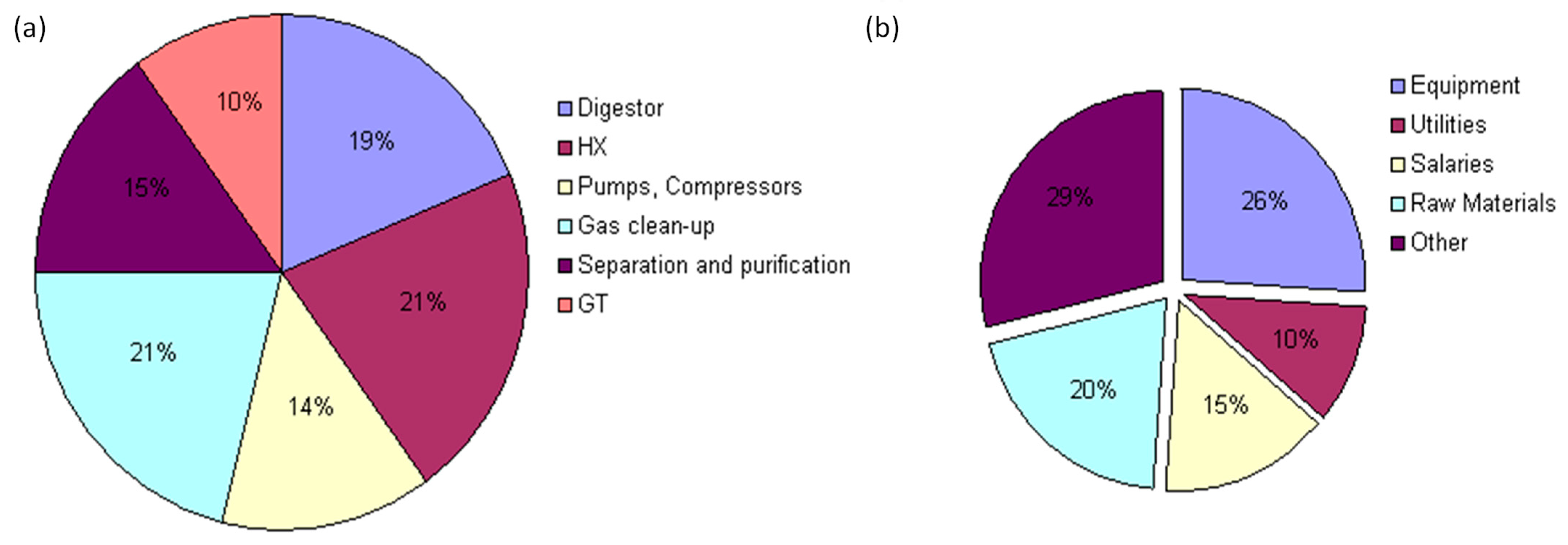
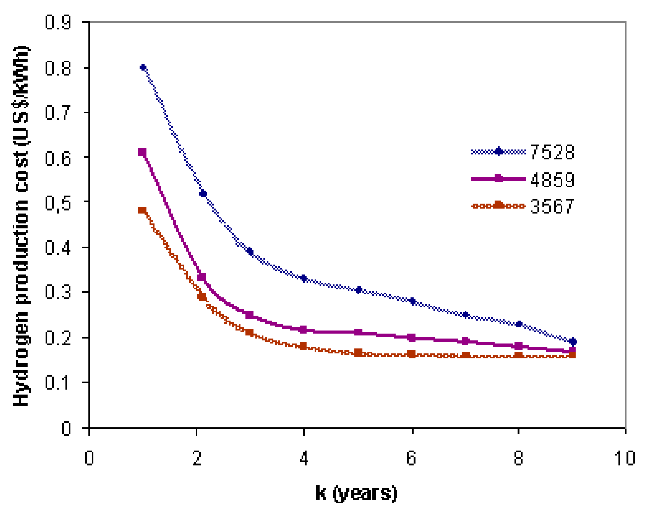
3.3. Results of the Financial Analysis

The hydrogen plant has a life of 25 years, with no further investment for the first 3 years. There is no revenue for the first 3 years after installation. The investment costs are 30%, 60%, and 90% of the TFCC. The payback occurs in the 4th year of operation. The real discount rate is 8.86%. The cost of hydrogen production varies between 0.14 and 0.24 EUR/kWh for 7528 h/year. The main economic indicators are summarized in Table 5. In brackets are the costs without the recycling of energy and materials. Material and energy recycling have a major impact on cost reduction.
Figure 5a shows the distribution of CAPEX costs for the operation of units used in the chemical process. The digester, steam reformer, and WSG reactor are the main contributors to equipment investment costs. The percentage of operation and maintenance costs is shown in Figure 5b. These cost values are comparable to those found in the literature [19,20].
Figure 6 shows the cost of hydrogen production as a function of a payback period for the amortization costs. It is possible to see that the cost of H2 production decreases with the amortization of investment costs. If the plant is operated for a longer period of time, i.e., 7528 h/year, the cost of hydrogen production increases due to the depreciation costs of the plant, but it reaches equilibrium after 9 years of operation. It can be seen that as the number of operating hours of the plant decreases, the depreciation costs decrease. The cost of hydrogen production of EUR 0.19/kWh is possible over 9 years.
Figure 7 shows the sensitivity analysis of the hydrogen production costs for the main variables in the biogas reforming process. It also provides an assessment of the effect of key variable on the economic performance. The hydrogen production costs decrease by 16.3% as the operation time increases from 5143 h/year to 7528 h/year. To calculate sensitive analysis variables, NPV, discount rate, sales volume, and depreciation costs were taken into account. The range of variation in hydrogen production costs shows the significant impact of variables on the final project result. The hydrogen price has a significant impact on the profitability of the hydrogen plant. The production of hydrogen, as a clean and renewable energy carrier, would steadily increase over time.

4. Conclusions

This paper discusses an industrial plant for the production of hydrogen from biogas by steam reforming. The treatment capacity of the plant is 4200 m3/h of biogas, from which 1260 kg/h of biomethane is produced, which is converted into 250.6 kg/h of hydrogen. The ecological, exegetic, and economic efficiency of the steam methane reformer and the water–gas shift reactor, with biogas purification, were calculated. The simulation ensures the conceptual design at the commercial scale, which has been simulated in CHEMCAD to evaluate techno-economic and environmental criteria. The total energy efficiency of the plant was 59.41%, while the exergy efficiency was 45.81%. The ecological efficiency obtained in the study (87.56%) contributes positively to the reduction of polluting gases. The total amount of electricity demand is reduced by the integration of heat (increased by 34.47%). Hydrogen production costs vary according to the main variables studied, which become more efficient by reducing the quantity of operating labor by improving automation technology. The basic design developed allows for the calculation of investment expenses, including the design, investor supervision, construction, and installation of equipment. The discussed financial installation does not include subsidies and basic certificates, nor the preferential financing of investments. The validation of the results was taken from literature datasets [2,3]. The possibility of converting biogas into hydrogen should be considered as a priority direction for energy diversification. The design of the biogas treatment plant is based on the use of domestic engineering potential and the possibility of biomethane production from biogas from a technical and economic point of view. This model analysis can help decision makers to choose different alternatives for swine manure waste management. In the future, it will be the investment in process optimization, depending on feedstock composition, which will ensure greater technological flexibility. These analyses will allow for future pilot plant investigations.

Author Contributions

Conceptualization, A.W., M.M. and A.S.; methodology, A.W., M.M. and A.S.; software, A.W.; validation, A.W. and M.M.; formal analysis, A.W. and M.M.; investigation, A.W. and M.M.; writing—original draft preparation, A.W.; writing—review and editing, A.W.; visualization, A.W.; supervision, A.S. All authors have read and agreed to the published version of the manuscript.

Funding

This material is based upon work supported by the Ministry of Science and Higher Education, Poland [Grant No. 11184013-324].

Data Availability Statement

All data generated or analyzed during this study are included in this published article.

Conflicts of Interest

The authors declare no conflict of interest.

References

  1. Srivastava, N.; Srivastava, M.; Malhotra, B.D.; Gupta, V.K.; Ramteke, P.W.; Silva, R.N. Nano engineered cellulosic biohydrogen production via dark fermentation: A novel approach. Biotechnol. Adv. 2019, 4, 321–325. [Google Scholar]
  2. Madeira, J.G.; Mendes de Oliveira, E.; Oliveira de Arau’ jo, V.; val Springer, M.; Lopes Cabral, H.; Silva Melgac, H. Optimum Co-digestion ratio of cattle manure and manipueira in a single-stage anaerobic digester for biogas production. Clean 2020, 48, 2000096. [Google Scholar]
  3. Boyano, A.; Blanco-Marigorta, A.M.; Morosuk, T.; Tsatsaronis, G. Exergo environmental analysis of a steam methane reforming process for hydrogen production. Energy 2011, 36, 2202–2214. [Google Scholar] [CrossRef]
  4. Zdeb, J.; Howaniec, N.; Smolinski, A. Experimental Study on Combined Valorization of Bituminous Coal Derived Fluidized Bed Fly Ash and Carbon Dioxide from Energy Sector. Energy 2023, 265, 126367. [Google Scholar] [CrossRef]
  5. Howaniec, N.; Smoliński, A.; Cempa-Balewicz, M. Experimental study of nuclear high temperature reactor excess heat use in the coal and energy crops co-gasification process to hydrogen-rich gas. Energy 2015, 84, 455–461. [Google Scholar] [CrossRef]
  6. Madeira, J.G.F.; Boloy, R.A.M.; Delgado, A.R.S.; Lima, F.R.; Coutinho, E.R.; de Castro Pereira Filho, R. Ecological analysis of hydrogen production via biogas steam reforming from cassava flour processing wastewater. J. Clean. Prod. 2017, 162, 709–716. [Google Scholar] [CrossRef]
  7. Cruz, P.L.; Iribarren, D.; Dufour, J. Exergy analysis of alternative configurations of a system coproducing synthetic fuels and electricity via biomass gasification, Fischer-Tropsch synthesis and a combined-cycle scheme. Fuel 2017, 194, 375–394. [Google Scholar] [CrossRef]
  8. Vidal, M.; Martín, M. Optimal coupling of biomass and solar energy for the production of electricity and chemicals. Comp. Chem. Eng. 2015, 72, 273–283. [Google Scholar] [CrossRef]
  9. Yingjian, L.; Qi, Q.; Xiangzhu, H.; Jiezhi, L. Energy balance and efficiency analysis for power generation in internal combustion engine sets using biogas. Sustain. Energy Technol. Assess. 2014, 3, 25–33. [Google Scholar] [CrossRef]
  10. Smolinski, A.; Wojtacha-Rychter, K.; Król, M.; Magdziarczyk, M.; Polański, J.; Howaniec, N. Co-gasification of waste-derived-fuel and bituminous coal with oxygen/steam blend to hydrogen rich gas. Energy 2022, 254, 124210. [Google Scholar] [CrossRef]
  11. Wojtacha-Rychter, K.; Smoliński, A. The interactions between coal and multi-component gas mixtures in the process of coal self-heating at different various temperatures ranges: An experimental study. Fuel 2018, 213, 150–157. [Google Scholar] [CrossRef]
  12. Urych, B.; Smoliński, A. Sewage sludge and phytomass co-pyrolysis and the gasification of its chars: A kinetics and reaction mechanism study. Fuel 2021, 285, 119186. [Google Scholar] [CrossRef]
  13. Lantz, M. The economic performance of combined heat and power from biogas produced from manure in Sweden—A comparison of different technologies. Appl. Energy 2012, 3, 502–511. [Google Scholar] [CrossRef]
  14. Kang, J.Y.; Kang, D.W.; Kim, T.S.; Hur, K.B. Comparative economic analysis of gas turbine-based power generation and combined heat and power systems using biogas fuel. Energy 2014, 4, 309–318. [Google Scholar] [CrossRef]
  15. Bruno, J.C.; Ortega-López, V.; Coronas, A. Integration of absorption cooling systems into micro gas turbine trigeneration systems using biogas: Case study of a sewage treatment plant. Appl. Energy 2009, 86, 837–847. [Google Scholar] [CrossRef]
  16. Peerapong, P.; Limmeechokchai, B. Biogas-based electricity generation in swine farm in Thailand: Economic and CO2 reduction aspects. Energy Procedia 2017, 138, 657–661. [Google Scholar] [CrossRef]
  17. Putmai, N.; Jarunglumlert, T.; Prommuak, C.; Pavasant, P.; Flood, A.E. Economic analysis of swine farm management for the enhancement of biogas production and energy efficiency. Waste Biomass Valorization 2020, 2, 5635–5645. [Google Scholar] [CrossRef]
  18. Xiao, Y.; Yang, H.; Yang, H.; Wang, H.; Zheng, D.; Liu, Y. Improved biogas production of dry anaerobic digestion of swine manure. Bioresour. Technol. 2019, 294, 122–188. [Google Scholar] [CrossRef] [PubMed]
  19. Soares, C.A.; Viancelli, A.; Michelon, W.; Sbardelloto, M.; Camargo, A.F.; Vargas, G.D.L.; Treichel, H. Biogas yield prospection from swine manure and placenta in real-scale systems on circular economy approach. Biocatal. Agric. Biotechnol. 2020, 101, 598–603. [Google Scholar] [CrossRef]
  20. Lee, T.-H.; Huang, S.-R.; Chen, C.-H. The experimental study on biogas power generation enhanced by using waste heat to preheat inlet gases. Renew. Energy 2013, 50, 342–347. [Google Scholar] [CrossRef]
  21. Braga, L.B.; Silveira, J.L.; da Silva, M.E.; Tuna, C.E.; Machin, E.B.; Pedroso, D.T. Hydrogen production by biogas steam reforming: A technical, economic and ecological analysis. Renew. Sustain. Energy Rev. 2013, 28, 166–173. [Google Scholar] [CrossRef]
  22. Chouhan, K.; Sinha, S.; Kumar, S.; Kumar, S. Simulation of steam reforming of biogas in an industrial reformer for hydrogen production. Int. J. Hydrogen Energy 2021, 46, 26809–26824. [Google Scholar] [CrossRef]
  23. Appari, S.; Janardhanan, V.M.; Bauri, R.; Jayanti, S.; Deutschmann, O. A detailed kinetic model for biogas steam reforming on Ni and catalyst deactivation due to sulfur poisoning. Appl. Catal. A 2014, 471, 118–125. [Google Scholar] [CrossRef]
Figure 1. Process flow diagram of biogas production (a); biogas to biomethane purification (b).
Energies 16 06389 g001
Figure 2. Process flow diagram of biomethane to hydrogen conversion.
Energies 16 06389 g002
Figure 3. H2 yield dependent on temperature and steam/methane ratio (a); volumetric gas composition dependent on temperature, %vol. (b); CO yield dependent on temperature and steam/methane ratio (c); CH4 conversion dependent on temperature and steam/methane ratio (d).
Energies 16 06389 g003
Figure 4. The effect of temperature and H2O/CH4 ratio on H2 yield(%) (a); CH4 conversion (%) (b).
Energies 16 06389 g004
Figure 5. Contributions of equipment and various items to costs: (a) the distribution of CAPEX costs for the operation of units used in the chemical process and (b) the percentage of operation and maintenance costs.
Energies 16 06389 g005
Figure 6. The cost of hydrogen production as a function of the payback period.
Energies 16 06389 g006
Figure 7. Variation in hydrogen production costs according to the main variables studied.
Energies 16 06389 g007
Table 1. Main thermodynamic parameters in the outflow for biogas purification to biomethane.
ParameterUnitFilterAbsorber AdsorberCleaned Gas
Temperature°C30754520
PressurekPa100489356108
CO2Composition, %28.780.000800
CH461.361.361.361.3
H2S11.9011.9000
NH30.002000
Solids0000
Table 2. Main thermodynamic parameters of biomethane to hydrogen conversion.
ParameterUnitReformer ReactorWater–Gas Shift ReactorFlash ColumnH2 Product
Temperature°C4563503838
PressurekPa108107.589106
Molar Flowkg·mole/h64.160.2459.5238.72
Mass Flowkg/h12601243.251240.81250.67
Heat FlowkJ/h−29,602,558.63−24,569,976.17−29,879,945.143258.17
Mass EnthalpykJ/kg−6358.17−7582.43−9186.87195.82
Mass EntropykJ/kg·C8.1412.7411.761.85
Mass DensityKg/m30.390.310.320.09
Vapor Fraction 0.750.820.7561
Table 3. Technology metrics evaluation for H2 production in mass balance.
ComponentMass Balance (kg/kgH2)
Biomethane5.26
Water steam14.87
Carbon monoxide7.25
Direct CO2 emissions0.16
Indirect CO2 emissions0.22
Table 4. Summary of energy demand efficiency for hydrogen production.
EquipmentElectricity Needs
(MWh/Mg H2)
Compressors0.31
Heating0.2286
Cooling0.352
Pumps0.29
Reactor Steam Reformer0.82
Reactor Water–Gas Shift Reactor0.35
Electricity Demand for Biogas Purification kWh/m30.029
η 59.41
ε 45.81
Table 5. Key metrics of plant economic indicators and costs, EUR.
CAPEX18,960,021
Material costs (with recycling), /h2405.85
Energy costs, /h326.6589
Total utility costs, /y4,309,855.2
Additional costs (fittings, valves, etc.)358,699.77
Depreciation costs, /y38,952.74
Revenue, /y7,509,213.4
Rate of return (without purchase equipment costs), /y8.86%
Disclaimer/Publisher’s Note: The statements, opinions and data contained in all publications are solely those of the individual author(s) and contributor(s) and not of MDPI and/or the editor(s). MDPI and/or the editor(s) disclaim responsibility for any injury to people or property resulting from any ideas, methods, instructions or products referred to in the content.

