
Analysis on DC Fault Current Limiting Operation of Twice-Quench Trigger Type SFCL Using Transformer Considering Magnetizing Current and Current Limiting Reactor

Abstract
:1. Introduction
2. Operational Characteristics and Experimental Circuit
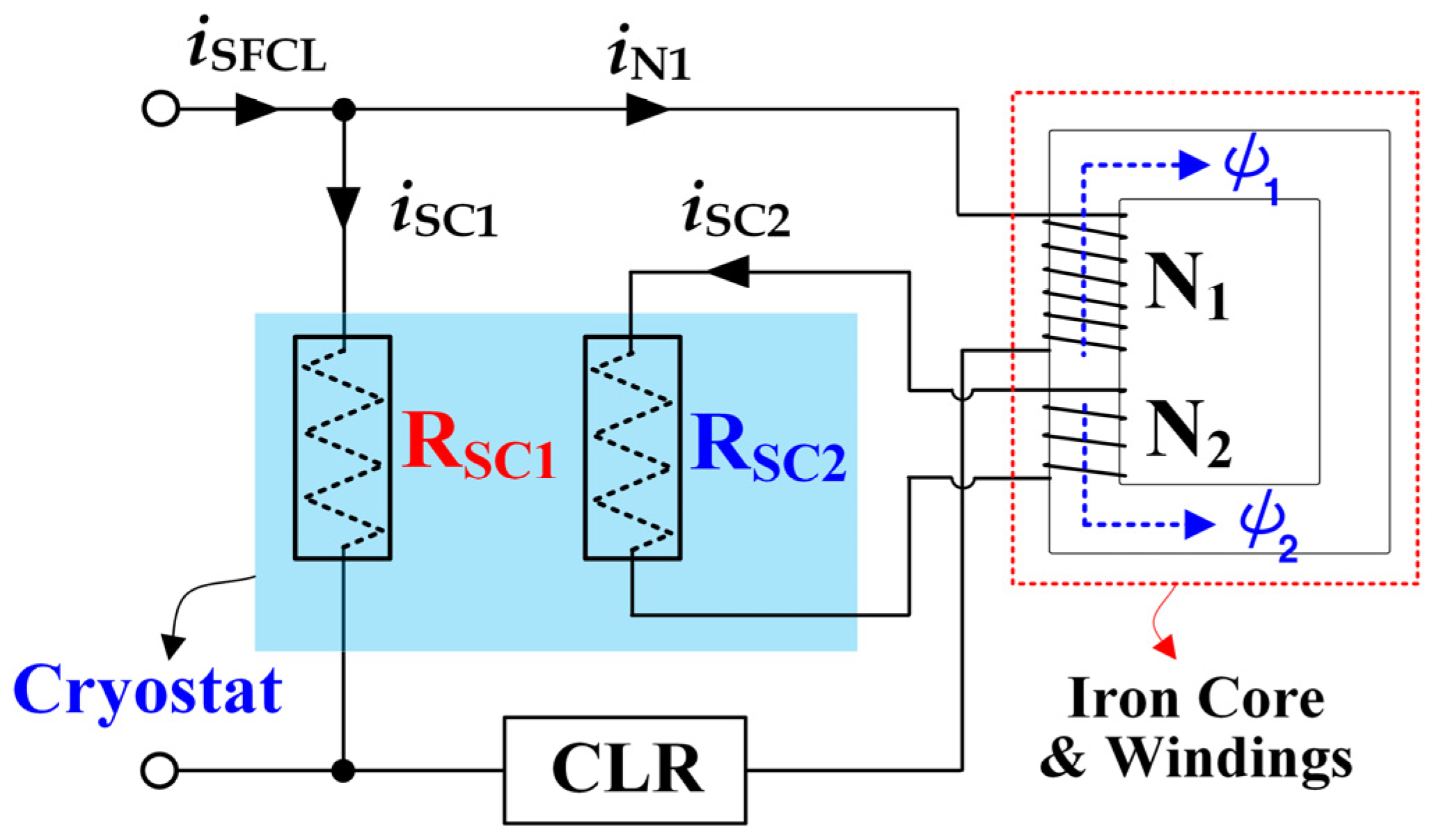
2.1. Operational Characteristics of Twice-Quench Trigger Type SFCL Using Transformer
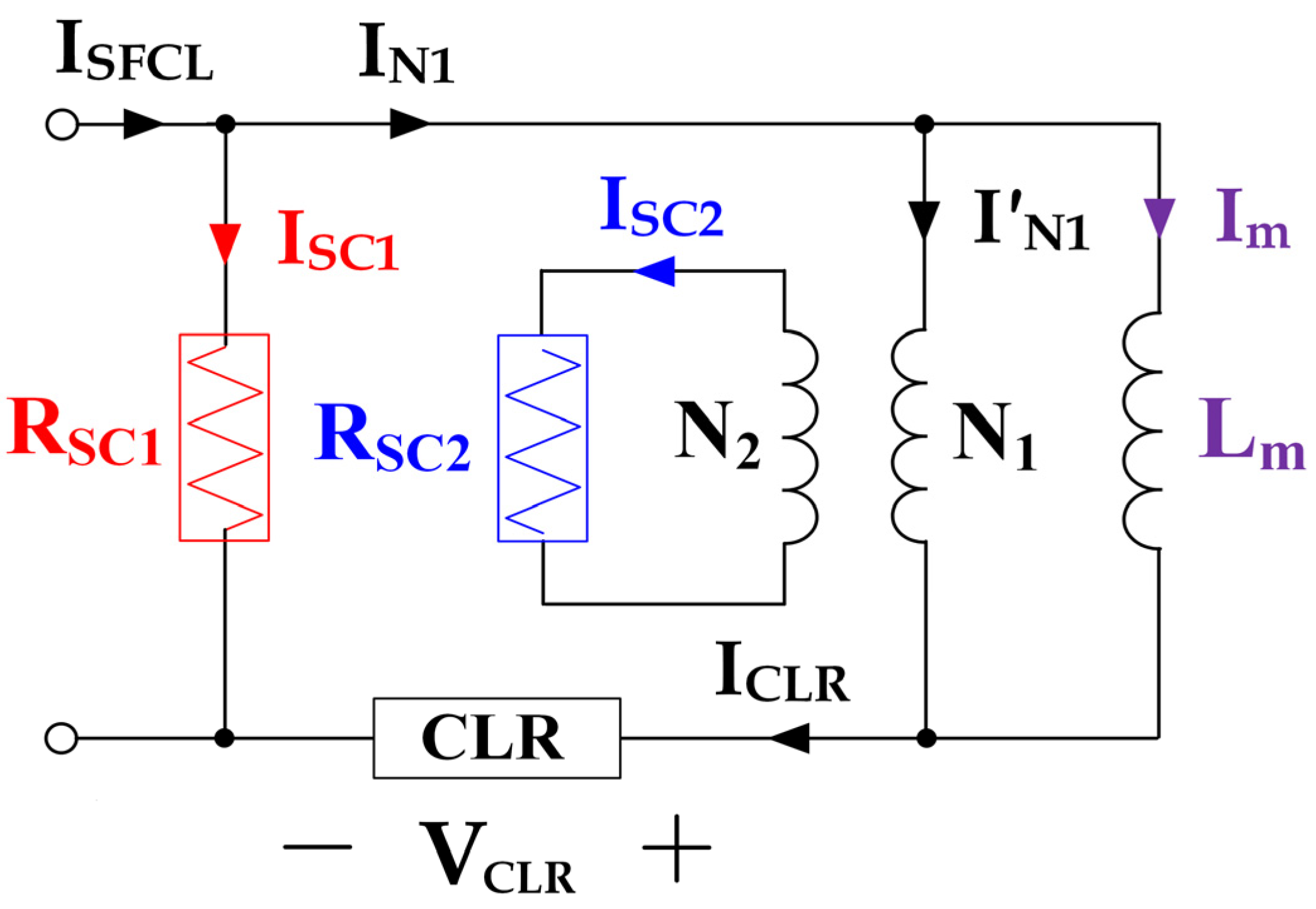
2.2. Equivalent Circuit of Twice-Quench Trigger Type SFCL Using Transformer
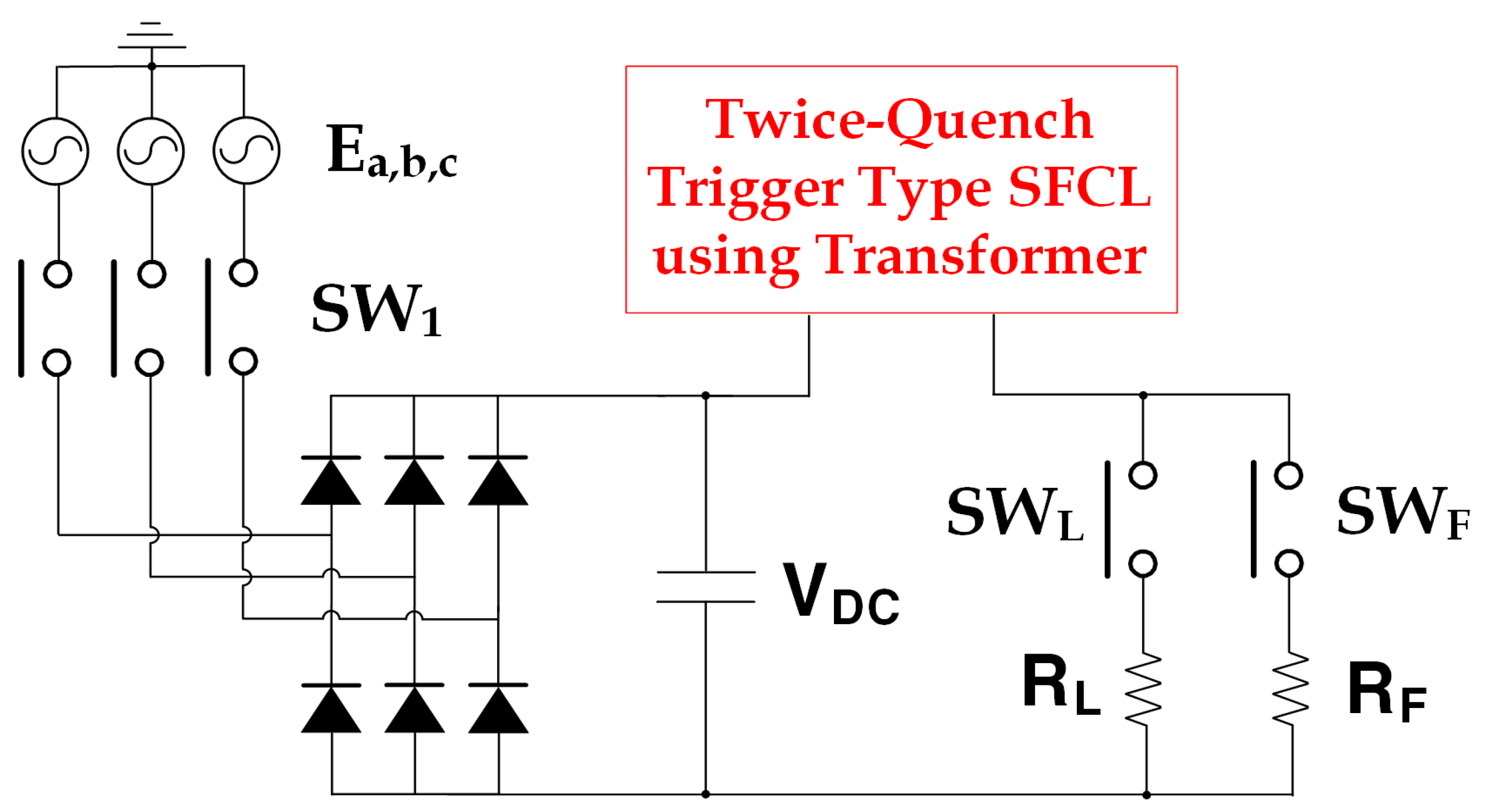
2.3. Configuration of DC Fault Experimental Circuit
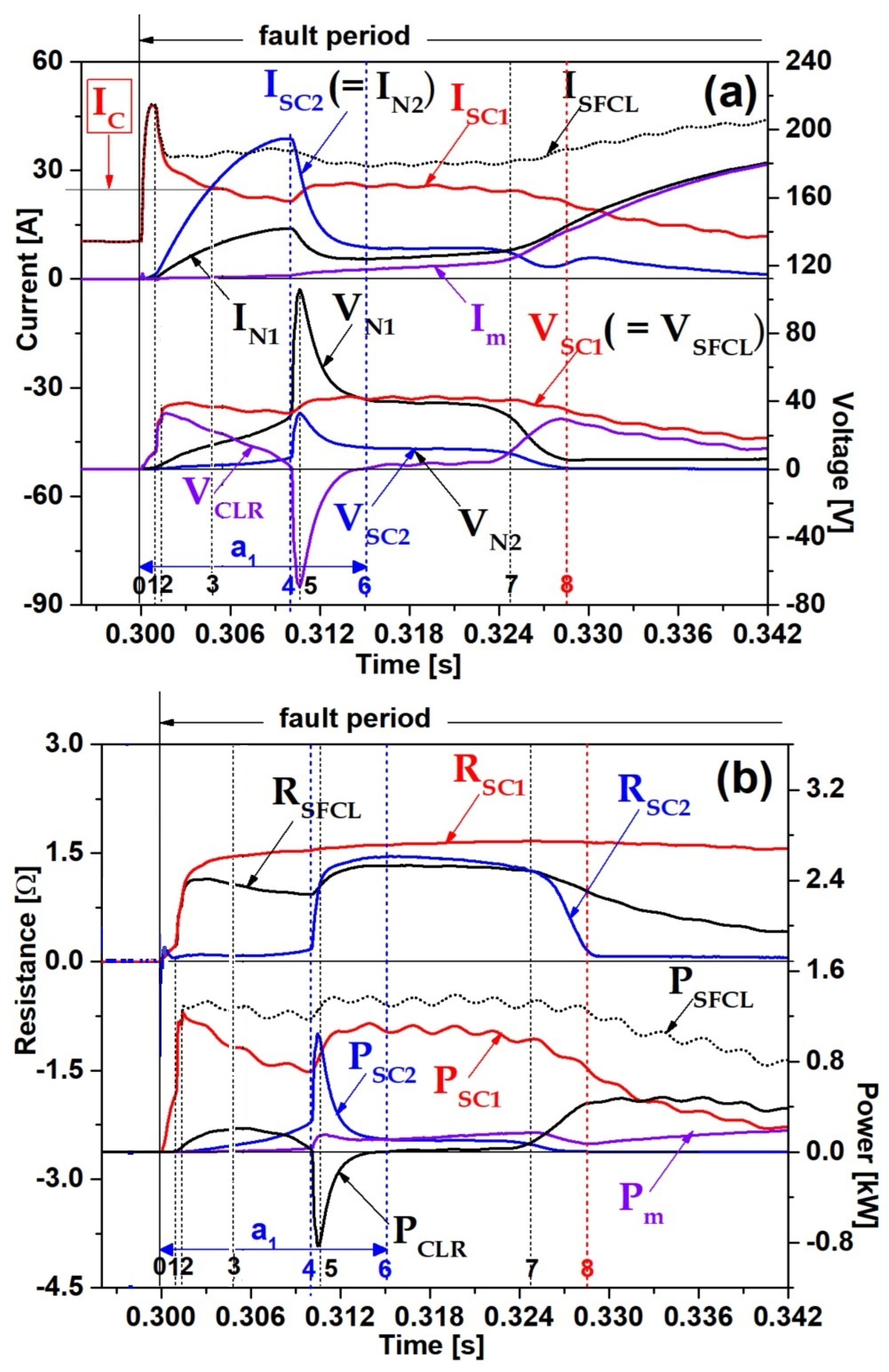
3. Result and Discussion
4. Conclusions
Author Contributions
Funding
Conflicts of Interest
References
- Samy, M.M. Computation of electromagnetic fields around HVDC transmission line tying EGYPT and KSA. In Proceedings of the 2017 Nineteenth International Middle East Power Systems Conference (MEPCON), Cairo, Egypt, 19–21 December 2017; pp. 1276–1280. [Google Scholar]
- Güven, A.F.; Samy, M.M. Performance analysis of autonomous green energy system based on multi and hybrid metaheuristic optimization approaches. Energy Convers. Manag. 2022, 269, 116058. [Google Scholar] [CrossRef]
- Shah, K.K.; Mundada, A.S.; Pearce, J. Performance of US hybrid distributed energy systems: Solar photovoltaic, battery and combined heat and power. Energy Convers. Manag. 2015, 105, 71–80. [Google Scholar] [CrossRef]
- Brenna, M.; Foiadelli, F.; Longo, M.; Abegaz, T.D. Integration and Optimization of Renewables and Storages for Rural Electrification. Sustainability 2016, 8, 982. [Google Scholar] [CrossRef]
- Bucher, M.K.; Franck, C.M. Fault Current Interruption in Multiterminal HVDC Networks. IEEE Trans. Power Deliv. 2016, 31, 87–95. [Google Scholar] [CrossRef]
- Rahimpour, S.; Husev, O.; Vinnikov, D. Design and Analysis of a DC Solid-State Circuit Breaker for Residential Energy Router Application. Energies 2022, 15, 9434. [Google Scholar] [CrossRef]
- Bayati, N.; Baghaee, H.R.; Savaghebi, M.; Hajizadeh, A.; Soltani, M.N.; Lin, Z. DC Fault Current Analyzing, Limiting, and Clearing in DC Microgrid Clusters. Energies 2021, 14, 6337. [Google Scholar] [CrossRef]
- Lee, H.; Asif, M.; Park, K.; Lee, B. Feasible Application Study of Several Types of Superconducting Fault Current Limiters in HVDC Grids. IEEE Trans. Appl. Supercond. 2018, 28, 1–5. [Google Scholar] [CrossRef]
- Lim, S.-H.; Han, T.-H.; Cho, Y.-S.; Choi, H.-S.; Han, B.-S.; Lee, S.-W. Quench characteristics of HTSC elements in integrated three-phase flux-lock type SFCL according to ground-fault types. Phys. C Supercond. Appl. 2007, 463, 1198–1203. [Google Scholar] [CrossRef]
- Hyun, O.-B.; Park, K.-B.; Sim, J.; Kim, H.-R.; Yim, S.-W.; Oh, I.-S. Introduction of a Hybrid SFCL in KEPCO Grid and Local Points at Issue. IEEE Trans. Appl. Supercond. 2009, 19, 1946–1949. [Google Scholar] [CrossRef]
- Lim, S.-H.; Lim, S.-T. Current Limiting and Recovery Characteristics of a Trigger-Type SFCL Using Double Quench. IEEE Trans. Appl. Supercond. 2018, 28, 17572499. [Google Scholar] [CrossRef]
- Aurangzeb, M.; Xin, A.; Iqbal, S.; Aymen, F.; Jasiński, M.; Jasińska, L. Utilizing Parallel Superconducting Element as a Novel Approach of Flux-Coupled Type SFCL to Limit DC Current in the System. Electronics 2022, 11, 3785. [Google Scholar] [CrossRef]
- Lee, J.-I.; Dao, V.Q.; Dinh, M.-C.; Lee, S.-j.; Kim, C.S.; Park, M. Combined Operation Analysis of a Saturated Iron-Core Superconducting Fault Current Limiter and Circuit Breaker for an HVDC System Protection. Energies 2021, 14, 7993. [Google Scholar] [CrossRef]
- Ko, S.-C.; Han, T.-H.; Lim, S.-H. Analysis on Double Quench and Instantaneous Power of SFCL Using Two Magnetically Coupled Windings According to Winding Direction. Energies 2020, 13, 5533. [Google Scholar] [CrossRef]
- Kim, Y.-P.; Ko, S.-C. DC Current Limiting Characteristics of Flux-Coupled Type SFCL Using Superconducting Element Connected in Parallel in a DC System. Energies 2021, 14, 1096. [Google Scholar] [CrossRef]
- Cho, K.-C.; Park, M.-K.; Lim, S.-H. Analysis of the DC Fault Current Limiting Characteristics of a DC Superconducting Fault Current Limiter Using a Transformer. Energies 2020, 13, 4210. [Google Scholar] [CrossRef]
- Kim, H.R.; Choi, H.S.; Lim, H.R.; Kim, I.S.; Hyun, O.B. Initial quench development in uniform Au/Y-Ba-Cu-O thin films. IEEE Trans. Appl. Supercond. 2001, 11, 2414–2417. [Google Scholar]
- Hyun, O.B.; Kim, H.R.; Sim, J.W.; Jung, Y.H.; Park, K.B.; Kang, J.S.; Lee, B.W.; Oh, I.S. 6.6 kV resistive superconducting fault current limiter based on YBCO films. IEEE Trans. Appl. Supercond. 2005, 15, 2027–2030. [Google Scholar] [CrossRef]
- Hyun, O.B.; Cha, S.D.; Kim, H.R.; Choi, H.S.; Hwang, S.D. Shunt-assisted simultaneous quenches in series-connected resistive SFCL components. IEEE Trans. Appl. Supercond. 2003, 13, 2060–2063. [Google Scholar] [CrossRef]


| Component | Parameter | Value | Unit |
|---|---|---|---|
| Source and Load/Fire Resistances | AC Voltage (Ea,b,c) | 80 | [Vrms] |
| Load Resistance (RL) | 10 | [Ω] | |
| Fire Resistance (RF) | 2.5 | [Ω] | |
| Twice-quench trigger type SFCL using transformer | Turns Ratio (N1/N2) of Primary and Secondary Windings | 3 | - |
| CLR | 6.6, 10 | [mH] | |
| HTSC Modules (RSC1, RSC2) | - | ||
| Fabrication Type | Thin Film | ||
| Material | YBCO | - | |
| Total Meander Line Length | 420 | [mm] | |
| Line Width | 2 | [mm] | |
| Thin Film Thickness | 0.3 | [µm] | |
| Gold Layer Thickness | 0.2 | [µm] |
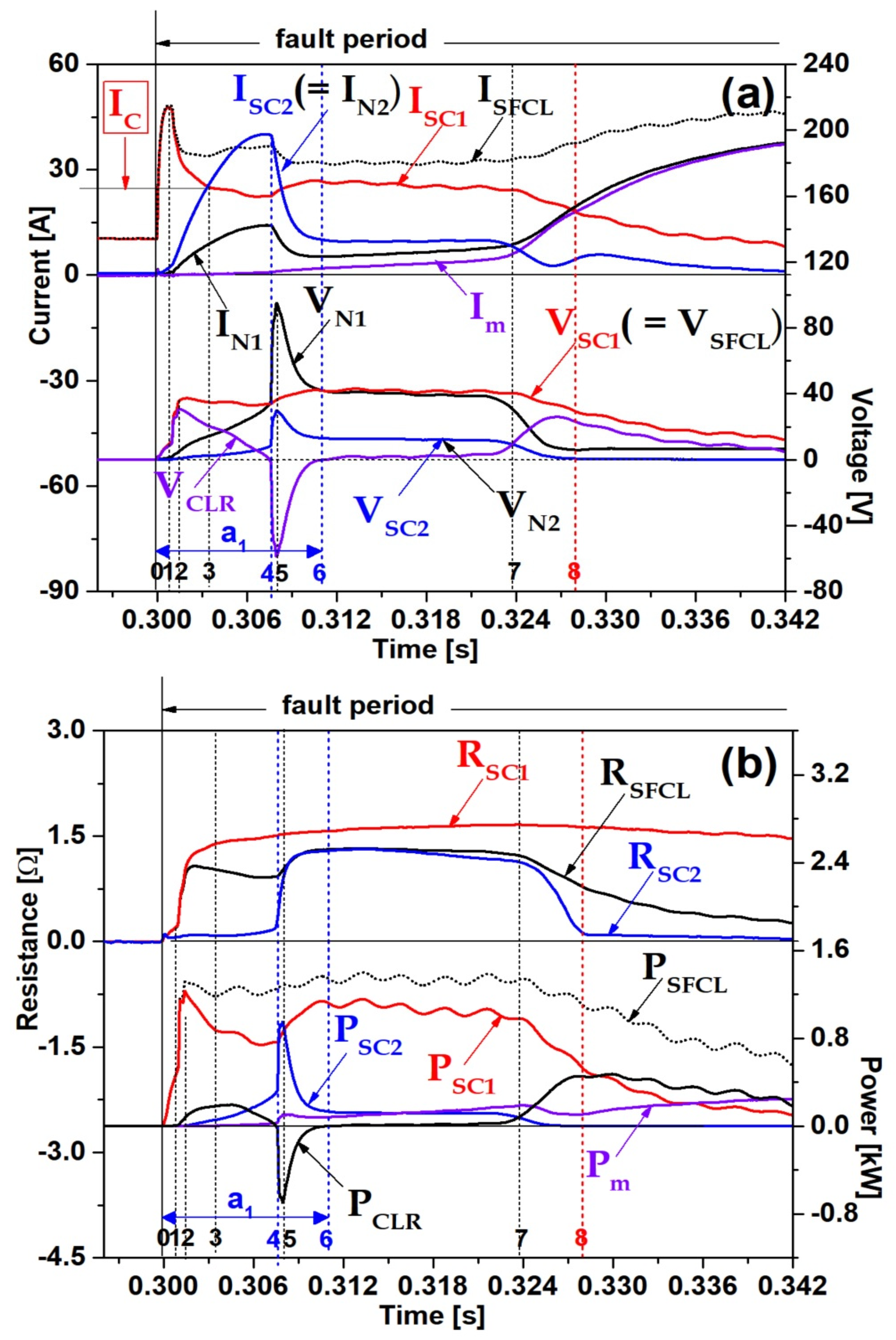
| Point Number | Description |
|---|---|
| 0 | DC fault starting point |
| 1 | First peak point of ISFCL |
| 2 | First peak point of VCLR |
| 3 | Recovery point into its critical current after current of first HTSC module (ISC1) exceeds its critical current (IC) |
| 4 | Falling point at zero value after VCLR has positive value |
| 5 | First peak negative point after VCLR arrives at zero value |
| 6 | Arrival point at zero value after VCLR becomes first peak negative point |
| 7 | Crossing point of VCLR and VN2 after charge and discharge of CLR |
| 8 | Arrival point at zero value of VN2 (=VSC2) after charge and discharge of CLR |
| Inductance of CLR [mH] | First Charge and Discharge Period [ms] | Second Charge and Discharge Period [ms] |
|---|---|---|
| 6.6 | 11 | 120 |
| 10.0 | 15 | 142 |
Disclaimer/Publisher’s Note: The statements, opinions and data contained in all publications are solely those of the individual author(s) and contributor(s) and not of MDPI and/or the editor(s). MDPI and/or the editor(s) disclaim responsibility for any injury to people or property resulting from any ideas, methods, instructions or products referred to in the content. |
© 2023 by the authors. Licensee MDPI, Basel, Switzerland. This article is an open access article distributed under the terms and conditions of the Creative Commons Attribution (CC BY) license (https://creativecommons.org/licenses/by/4.0/).
Share and Cite
Lim, S.-H.; Park, M.-K.; Park, S.-H.; Chung, J.-W. Analysis on DC Fault Current Limiting Operation of Twice-Quench Trigger Type SFCL Using Transformer Considering Magnetizing Current and Current Limiting Reactor. Energies 2023, 16, 6299. https://doi.org/10.3390/en16176299
Lim S-H, Park M-K, Park S-H, Chung J-W. Analysis on DC Fault Current Limiting Operation of Twice-Quench Trigger Type SFCL Using Transformer Considering Magnetizing Current and Current Limiting Reactor. Energies. 2023; 16(17):6299. https://doi.org/10.3390/en16176299
Chicago/Turabian StyleLim, Sung-Hun, Min-Ki Park, Sung-Hoon Park, and Jae-Woo Chung. 2023. "Analysis on DC Fault Current Limiting Operation of Twice-Quench Trigger Type SFCL Using Transformer Considering Magnetizing Current and Current Limiting Reactor" Energies 16, no. 17: 6299. https://doi.org/10.3390/en16176299
APA StyleLim, S.-H., Park, M.-K., Park, S.-H., & Chung, J.-W. (2023). Analysis on DC Fault Current Limiting Operation of Twice-Quench Trigger Type SFCL Using Transformer Considering Magnetizing Current and Current Limiting Reactor. Energies, 16(17), 6299. https://doi.org/10.3390/en16176299