1. Introduction
An increase in the energy efficiency of technological equipment is one of the critical points according to Industry 4.0 [
1] because of the contribution to improving energy efficiency by an average of 15–25% within this strategy implementation [
2] while also ensuring the efficiency of enterprises can be realized by rational selection of the manufacturing process [
3].
Abrasive jet machining (AJM) is widely used for cleaning the surfaces of various materials [
4]. Recently, the trend of using sandblasting cameras has been increasing [
5]. This has been facilitated by new types of abrasives, the improvement of sandblasting devices, and the spread of chemical coatings before the application of which the treated surface should be effectively cleaned. AJM allows for cleaning metal surfaces without damaging the surface structure [
6]. The appearance of new materials also leads to expanding the possibilities of AJM.
Since the related devices should offer a cost-effective and energy-efficient solution to maintain and enhance equipment performance in the energy industry, ensuring sustainable and environmentally friendly energy production, the problem of developing rational ways to increase their energy efficiency is topical.
Before formulating the primary purpose of the research, the state of the art should be highlighted. Particularly, Ahmed and Chen [
7] used the capture factor as a key parameter to describe the performance of the ejector. This coefficient was determined as the mass of the trapped working flow divided by the mass flow rate of the driving flow.
Van den Berghe et al. [
8] developed a new 1D transient model for ejectors based on a pipeline analogy for gas-dynamic calculations. This model was based on the non-stationary Euler’s equation. Yan et al. [
9] checked CFD simulations for the model with two phases within the permissible range of discrepancies. As a result, a positive effect of up to 30% was reached due to the optimization of the nozzle’s geometric parameters. This confirmed the significant impact of the nozzle’s geometry on its flow characteristics.
Xu et al. [
10] studied a phenomenon similar to the abrasive jet nozzle’s wear during operation. As a result, it was established that particle size, mass flow rate, and installation position essentially impact the nozzle’s wear. Li et al. [
11] carried out numerical simulations of the internal flow structure in the jet system. The nozzle diameter was a key parameter affecting the performance and structure of the internal flow. Aronson et al. [
12] presented the impact of geometric characteristics on multistage jet ejectors.
Bañon et al. [
13] considered the effect of shot blasting for removing significant contaminants. It was determined that increased pressure creates a greater ability for particle erosion. Kwon and Lee [
14] also studied AJM. As a result, it was established that particle type, nozzle diameter, pressure, distance, and processing time affect the surface characteristics. Sychuk et al. [
15] assessed the following durability of nozzles from various materials: ceramic—1–2 h, cast iron—6–8 h, tungsten carbide—approximately 300 h, and boron carbide—750–1000 h.
The nozzle flow profile also directly affects the velocity distribution of pressure, density, and temperature. It is closely related to the internal losses of the nozzle. Therefore, the performance improvement due to the optimal flow profile is significant. Under similar conditions, the particle capture ratio increases by 8–19% compared to a conventional ejector [
16]. Also, Venturi nozzles achieve 4–7 times more aeration performance than circular ones [
17].
During the AJM operation, properly mixing the abrasive material with air is also essential. Xi et al. [
18] showed the correctness of using high-frequency oscillations to increase the efficiency of mixing two-phase flows. As a result, a significant increase in productivity (up to 14%) was achieved. Also, Han et al. [
19] found that sand grains in the nozzle contribute to cavitation flow development. In this case, the concentration range became smaller with an increase in the average diameter. Other achievements in using hydrodynamic cavitation for the enhancement of the efficiency of fluid working medium preparation technologies were discussed by Fesenko et al. [
20].
Zabolotnyi et al. [
21,
22] proposed a technology to obtain long-length, permeable powder materials with uniform density distribution and stable operational characteristics. Somov et al. [
23] developed an experimental stand to process powder materials using a vibratory actuator.
Moreover, Sychuk et al. [
24] applied a technology of effective abrasive jet machining of parts surfaces. The developed nozzle design allowed for forming an air layer on the inner surface to reduce the contact of the abrasive airflow with the nozzle surface and increase the durability and energy efficiency of the AJM. Finally, Povstyanoy et al. [
25] tested the porous nozzle for AJM. As a result, this made it possible to increase the efficiency of material processing significantly.
Thus, AJM needs an energy-intensive unit that consumes energy significantly in a range of 10–100 kW, depending on the application. Using worn nozzles also leads to excessive use of compressed air and abrasive material. The decisive factors for successfully operating the abrasive jet unit are a powerful source of compressed air and an energy-efficient abrasive jet nozzle. This affects the consumption of compressed air and abrasive material and the efficiency of AJM.
Notably, the main factors of AJM are flow rate, an angle between the jet and the machined surface, abrasive fraction and grain size, abrasive concentration in the flow, and the kinetic and dynamic characteristics of the abrasive jet equipment.
Despite many efforts devoted to studying the designs of abrasive jet devices, the following research gaps remain unsolved. Firstly, the determination of the correct values of flow rate for cylindrical nozzles operating on an abrasive–air mixture is needed. Such a ratio should consider peculiarities of the flow of the working mixture through the nozzle and allow for more precisely evaluating the mass flow rate of the abrasive flow.
Secondly, analytical dependencies for the mass flow rate and the corresponding flow ratio depending on the nozzle’s diameter should be identified. Such dependencies should correspond to the experimentally obtained data and properly approximate them.
Finally, the possibility of a rational choice of geometric characteristics for working nozzles operating on an abrasive–air mixture should be realized.
All the above-mentioned factors should allow for increasing the efficiency of the working nozzles during AJM due to the impact on geometric parameters and operating modes. Therefore, the assumption that the rational choice of the geometrical characteristics can increase AJM efficiency is the central hypothesis of the research.
Overall, the article aims at ensuring the energy efficiency of AJM. The following research objectives were formulated to achieve this goal. Firstly, numerical and experimental studies of AJM for various working nozzles’ geometric parameters and operating modes should be conducted. For this purpose, the experimental stand should be designed.
Secondly, the obtained experimental results should be analyzed in terms of the possibility of ensuring energy efficiency. For this purpose, the regression analysis should be applied. Finally, rational geometric parameters to increase the efficiency of AJM should be developed.
2. Materials and Methods
2.1. Analytical Approach
The approaches to calculating and designing nozzle elements with relatively small cross-sections (e.g., cylindrical and conical nozzles, holes with sharp edges) were based on generalized experimental data. For example, for the labyrinth seal case study, the design was represented as a series of sequentially installed holes with sharp edges. A conditional flow ratio was also introduced. It allowed for considering all the available assumptions and simplifications.
The flow characteristics of the nozzle for AJM were also calculated according to the same principle. However, existing methods of analytical calculation of mass flow through a channel with a sharp edge have differences of up to 30% [
26].
Under such circumstances, the fundamental Stodola’s formula was chosen to evaluate the mass flow rate through a channel [
27]:
where
μ—nozzle’s flow ratio;
ka—adiabatic exponent;
f—cross-sectional area, m
2;
ρ1—inlet density, kg/m
3;
p1—inlet pressure, Pa;
p2—outlet pressure, Pa;
z—the number of sequentially installed holes with sharp edges.
The coefficient
μ, which considers the peculiarities of the abrasive material flow, was evaluated experimentally, as presented in
Section 3.
2.2. Numerical Simulations
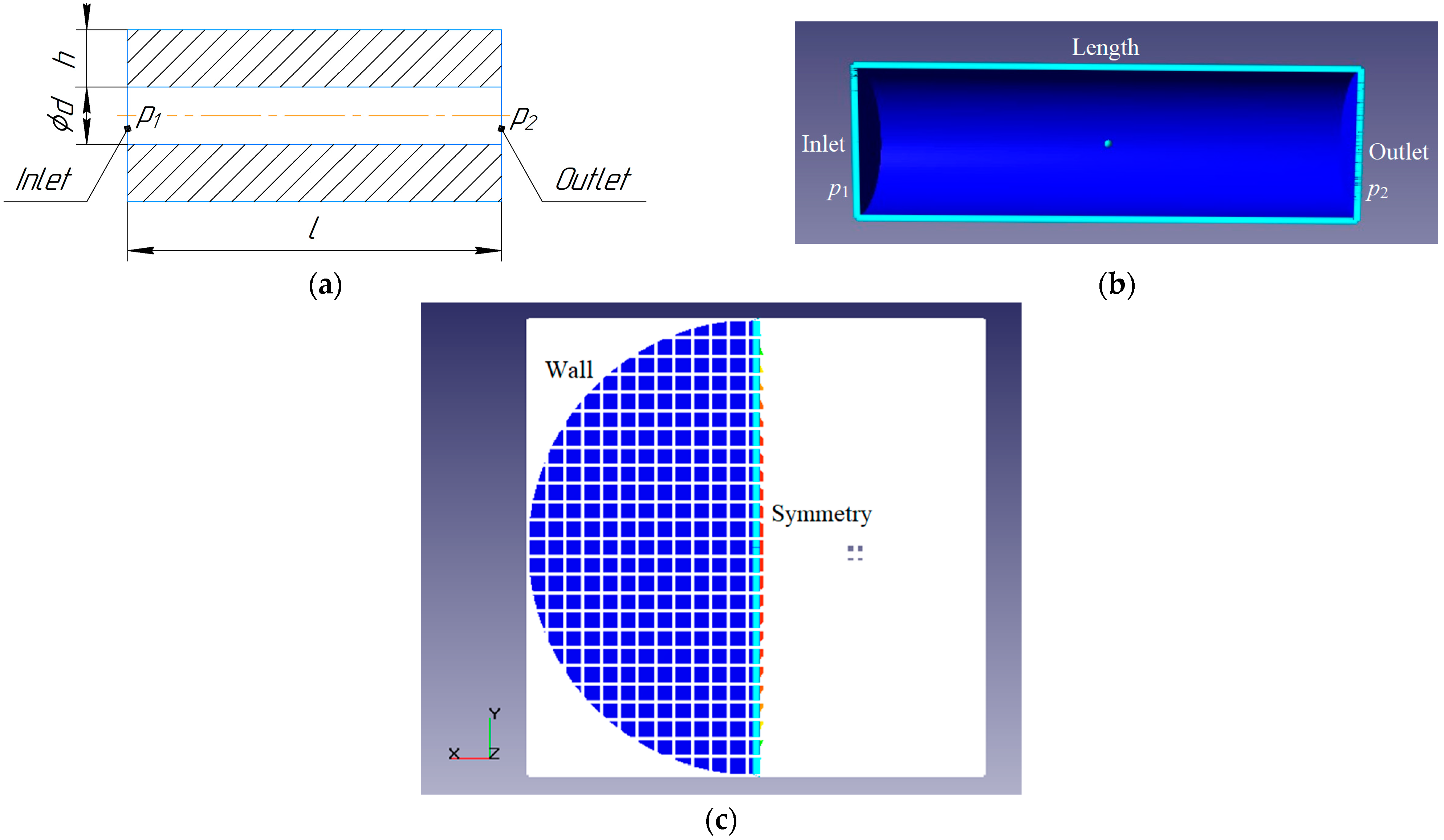
Numerical simulations were performed to establish the impact of the nozzle diameter on the actual and theoretical values of the mass flow rate. The studies were carried out using the FlowVision CFD 2.5.3 software (Idasugiyama-cho, Japan). The scheme of the numerical simulations is presented in
Figure 1.
The flow model was fully compressible fluid with two-phase medium activation (particle option). This model allowed for simulating two-phase flows with particles. The carrier phase can be liquid or gas. Particles can be solid balls, drops, or bubbles. Abrasive particles have diameters from the 0.1–1.0 mm range.
An implicit calculation scheme was used. The particle motion model supplemented the compressible fluid model. Mutual influence of phases was assumed. Therefore, the carrier phase determines the particle trajectories. Particles, in turn, affect the flow through mass, momentum, and energy conservation laws.
The nozzle wall was impermeable and adiabatic, and the slip boundary condition was used for the continuous (gas) phase at the nozzle wall. The normal and tangent reflection coefficient 1.0 was applied for the dispersed (particle) phase.
At the inlet, the variable pressure was applied for the continuous phase. The dispersed phase had the same pressure and temperature as the continuous phase but with a variable mass fraction. Other boundary conditions were similar to the continuous phase.
The pressure drop to atmospheric was considered at the nozzle’s outlet.
The temperature of particles was 300 K, the average particle size was 0.5 mm, the average distance between particles was 0.5 mm, and the particle surface degree was 1.0. Also, a coincidence of the particles’ initial speed with the carrier phase’s local speed was given.
A series of simulations using calculation mesh with different numbers of cells was carried out to identify the proper mesh selection. As a result, the calculation mesh was chosen with the number of cells of about 1.1 × 10
5 (
Figure 2).
Figure 2 also contains the following geometric parameters:
l—nozzle length, m;
h—wall thickness, m.
The program software operates with the following turbulence models: Spalart–Allmaras (S.A.), Menter’s shear stress transport (SST), the low-Reynolds turbulent model (AKN) by Abe–Kondoh–Nagano, and the standard
k-
ε model. The previous research work [
27] proved that the turbulence model does not significantly affect the change in pressure differences for channels with a high length-to-diameter ratio and, therefore, the mass flow rate through the gap. Moreover, throttling in a nozzle is similar to a labyrinth seal, where the pressure drop ratio
p1/
p2 does not exceed 1.2, and the walls of the calculated nozzle models are assumed to be hydraulically smooth.
Therefore, during the numerical simulations, the standard
k-
ε turbulence model was chosen because it agrees with most studies on gas flow. The corresponding equations for the turbulent kinetic energy
k and the turbulent dissipation energy
ε are as follows [
28]:
where
ρ—flow density, kg/m
3;
t—time, s;
xi—the
i-th coordinate, m;
ui—velocity component in the
i-th direction, m/s;
μt—turbulent viscosity, Pa·s;
Eij—the strain rate components (
i,
j = 1, 2, 3). Also, Equations (2) and (3) contain the following parameters:
σk = 1.0,
σε = 1.3,
C1ε = 1.44, and
C2ε = 1.92 [
29].
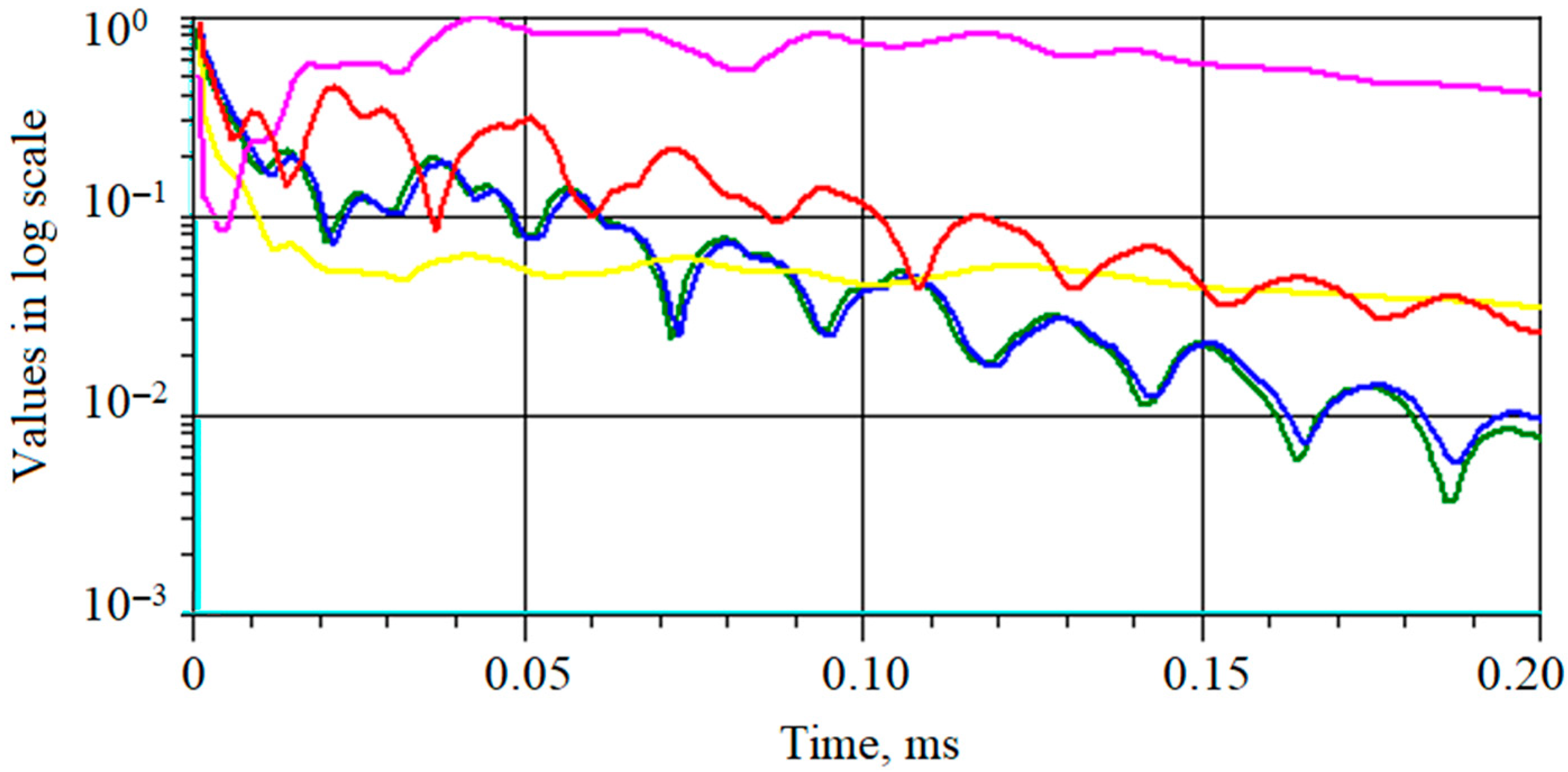
For the chosen model of a fully compressible fluid, the time step depends on the convergence of the pressure equations. As an example, the convergence of numerical simulation results by various physical parameters (pressure, velocity magnitude, and their pulsations) is presented in
Figure 3.
Equality of mass flow rates at the inlet and the outlet was the primary convergence criterion for establishing the stationary flow mode in the compressor, which means the completion of the calculation.
The transition of the abrasive jet equipment to the operating mode was characterized by the pressure ratio of p1/p2 = 1.98.
2.3. Experimental Studies
Verification of numerical simulation results was carried out by conducting a series of experimental studies. The scheme of the experimental research is presented in
Figure 4.
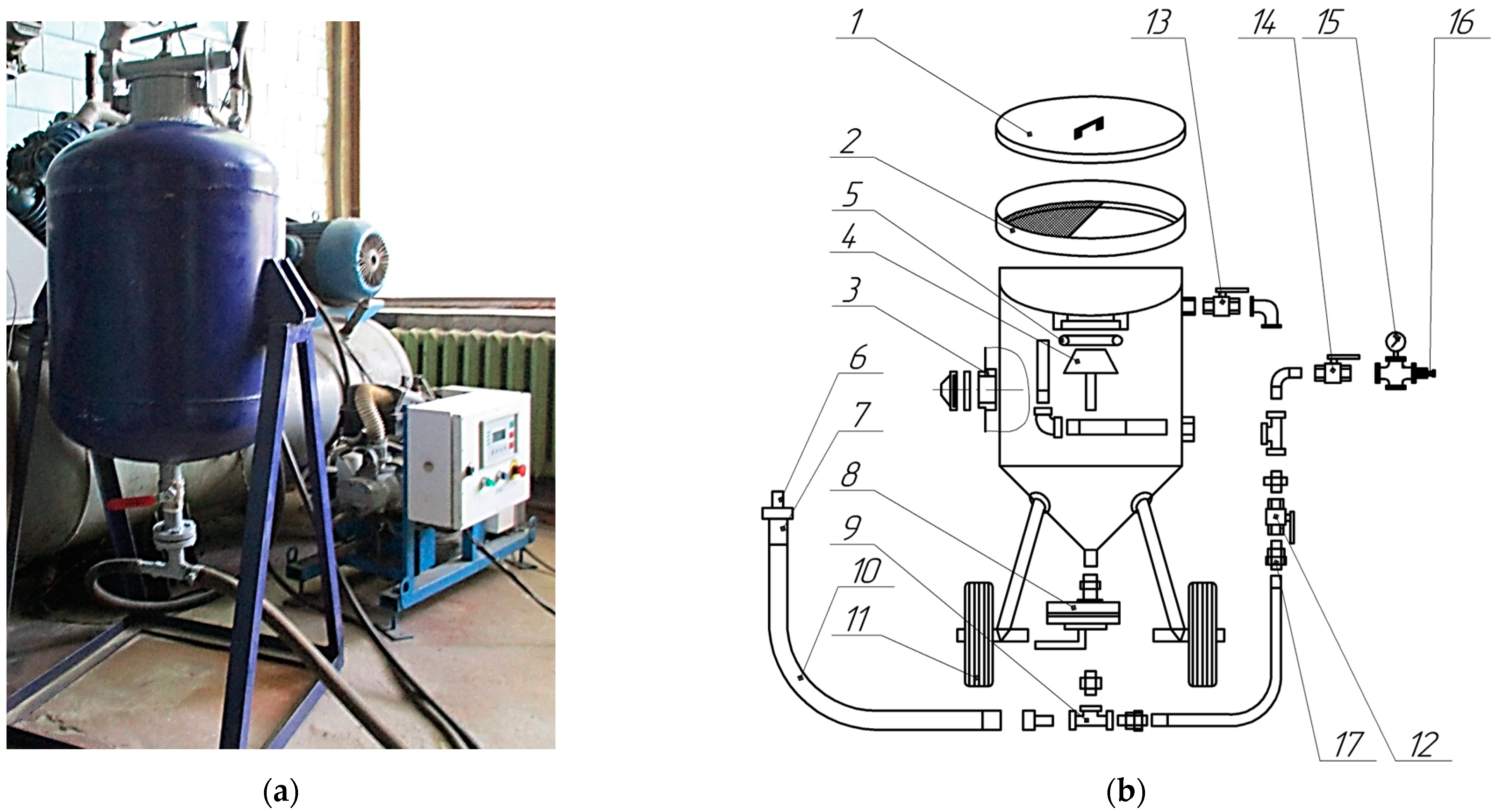
An experimental stand was installed to conduct the research (
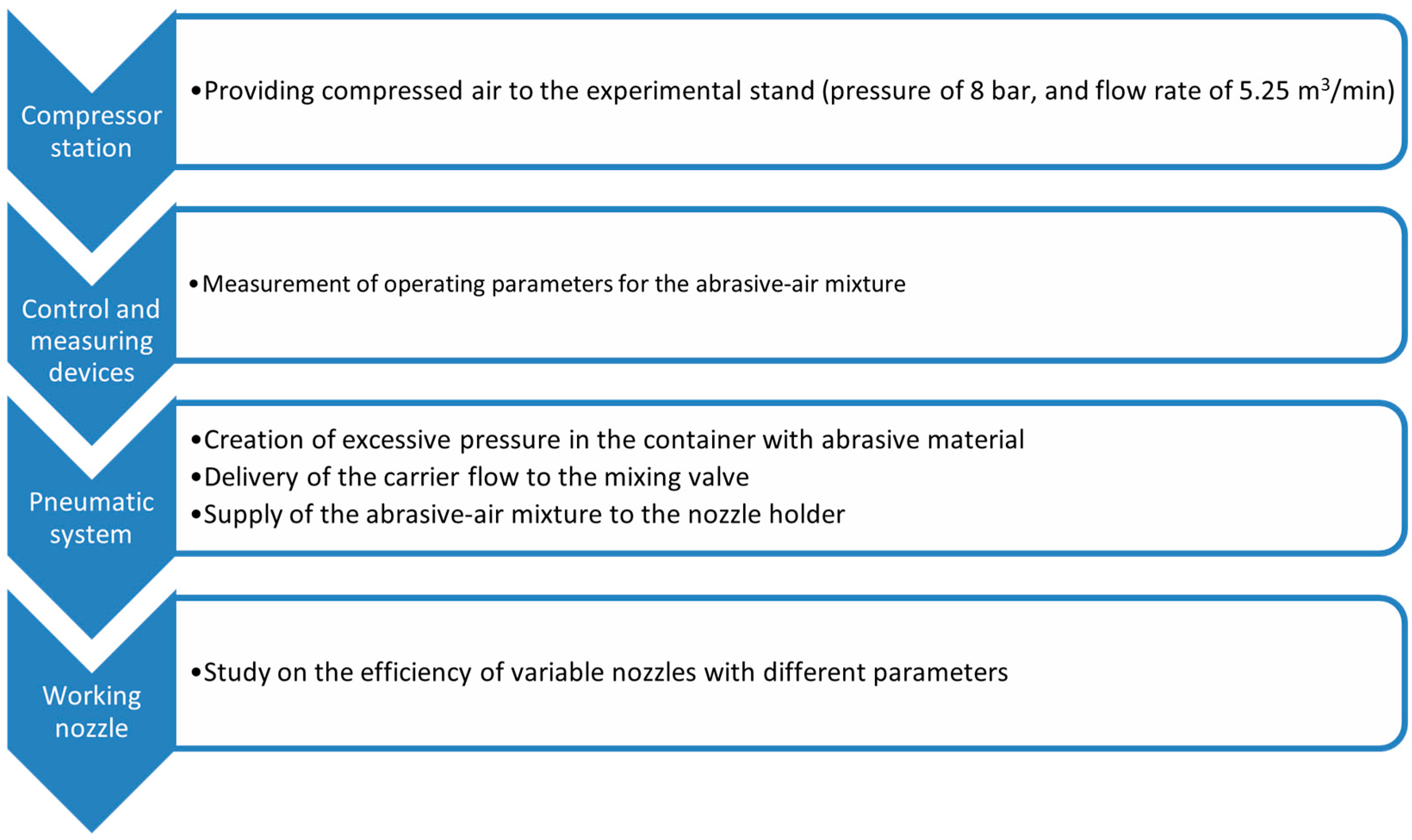
Figure 5).
The experimental stand includes the tested nozzle 6, a container with sand, a binding armature, and a portable compressor station with the following parameters: volume flow rate 5.25 m3/min, maximum injection pressure 800 kPa, and power of the electric motor 40 kW.
The compressor station can supply air to two abrasive jet devices at full capacity. However, due to a relatively energy-consuming compressor, frequent starts lead to overheating motor and the switching elements. Therefore, it is profitable to adjust the operation of the abrasive jet device in such a way as to reduce air consumption and the machining time per unit of the metal surface area.
The stand operates as follows. The abrasive material enters a hermetic container through sieve 2. Compressed air enters the tee 9 through the inlet valve 14, which picks up part of the abrasive material. Its supply is regulated by sand shutter 8. The air–abrasive mixture enters nozzle 6 through sleeve 10.
The experimental studies measured air flow rate, pressure, temperature, and amount of abrasive material. The volume of sand in the installation is 0.2 m3. River sand with a fraction in a range of 0.5–0.8 mm was used as an abrasive material.
The experimental setup allowed for research at variable operating pressure before and after the nozzle and changing the tested nozzles in a wide range of geometric parameters. The studied parameters were inlet pressure of 101 kPa, mass flow rate of 0.023–0.24 kg/s, nozzle diameter d = 2–20 mm, and length l = 4–44 mm. This allowed for rationally selecting the operating and geomantic parameters to improve the energy efficiency of the available working nozzles.
The values of the measurement errors for the actual flow rate of air and abrasive material were controlled before the gas flowmeter and directly in front of the nozzle. The “RG 250” flowmeter measured the air flow rate with an accuracy class of 1.0. The deformation manometer “D.M. 05-MP-3U” with a maximum pressure of 2 MPa and an accuracy class of 1.5 measured the pressure. The temperature was controlled by the “Testo 905-T2” thermometer. The amount of abrasive was measured by scales “KS10”, with a maximum loading of 10 kg and a tolerance of 1 g.
The measurement error of the main parameter
μ was evaluated by indirect measurements technique [
30].
3. Results
3.1. Experimental Results
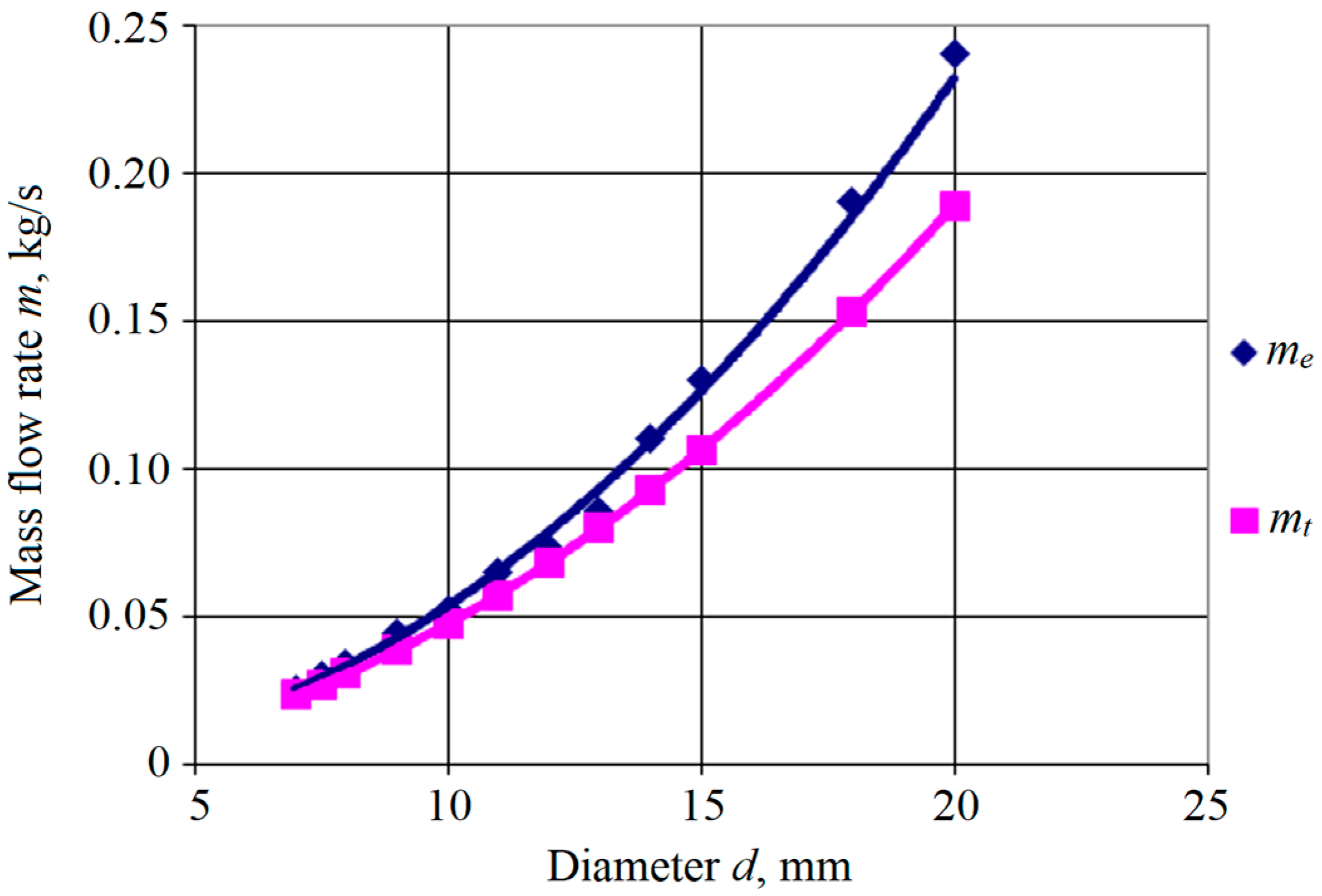
The main geometric parameter of the nozzle is its inner diameter. Therefore, numerical experiments were conducted to establish its impact on the experimental and theoretical mass flow rate
m, kg/s. As a result, the following power dependence of the mass flow rate on the nozzle diameter was proposed (
Figure 6):
where
d—inner diameter of a nozzle, m;
dmin—minimum nozzle’s diameter under consideration, m;
mmin—mass flow rate for a nozzle with minimum diameter, kg/s;
n—dimensionless regression coefficient.
Figure 6 shows experimental
me and theoretical
mt mass flow rates, respectively. Line 1 corresponds to the experimentally obtained mass flow rates
me, kg/s. Line 2 is the theoretical curve for the mass flow rate
mt evaluated by Formula (1), kg/s.
The approximating dependence (4) reflects an increase in the mass flow rate m by an increase in the diameter d. Also, for the minimum diameter, the mass flow rate corresponds to its minimum value: m(dmin) = mmin.
Unknown parameters
mmin and
n were evaluated by the experimental data by minimizing the following mean square error (MSE) between logarithms of analytical dependence (4) and experimental data:
where
i—experimental point index;
N—the total number of experimental data;
di—
i-th nozzle’s diameter, m;
mi—experimentally obtained mass flow rate, kg/s.
MSE (5) reaches its minimum under the following conditions:
which directly corresponds to the following matrix equation:
The inverse matrix approach allowed for evaluating the estimated parameters:
According to Formulas (8) and (9), the evaluated parameters mmin and n were as follows: mmin = 0.025 kg/s; n = 2.12 for the case of me, and n = 2.0—for the case of mt.
Remarkably, the flow ratio also increases the mass flow rate. Therefore, to maintain the performance of a worn nozzle, 8–10 times more air and abrasive material consumption is required. This significantly increases the cost of AJM.
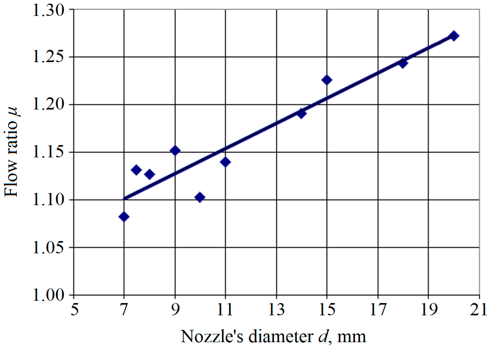
However, experimentally and theoretically obtained flow rates differed insignificantly. Therefore, the approximation of the flow ratio became linear. Particularly,
Figure 7 demonstrates an increase in the flow rate by an increase in the inner diameter at a constant pressure drop:
where
μmin—the flow ratio for a nozzle with minimum diameter
dmin;
α—regression coefficient, m
−1.
The experimental data allowed for evaluating unknown parameters
μmin and
α by minimizing the following MSE between logarithms of analytical dependence (10) and experimental data:
where
μi—experimentally obtained flow ratio; Δ
di—the difference between
i-th nozzle’s diameter and minimum diameter
dmin, m.
MSE (11) reaches its minimum under the following conditions:
that directly correspond to the following matrix equation:
The inverse matrix approach allowed for evaluating the estimated parameters:
According to Formulas (15) and (16), the evaluated parameters μmin and α were as follows: μmin = 1.10, and α = 1.27.
The productivity of processing was also experimentally determined. It significantly depended on the pressure of compressed air. The flow rate depended on the nozzle diameter; it permanently increased due to wear.
Overall, the geometric and operational parameters of the nozzle are summarized in
Table 1.
The higher the ratio μ, the better the nozzle works. This is because the nozzle should pass the maximum amount of abrasive material, giving it maximum speed.
3.2. Numerical Simulation Results
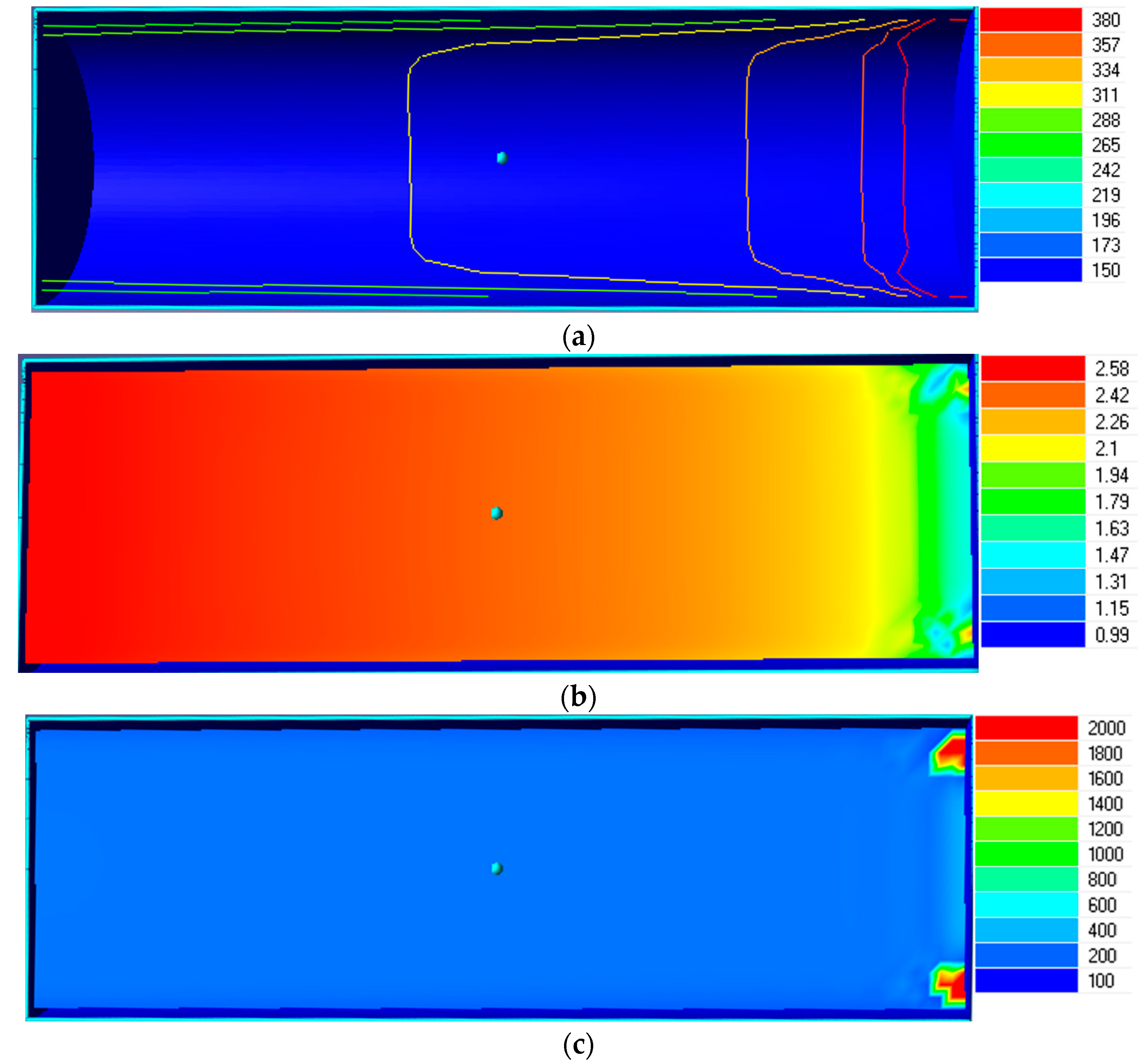
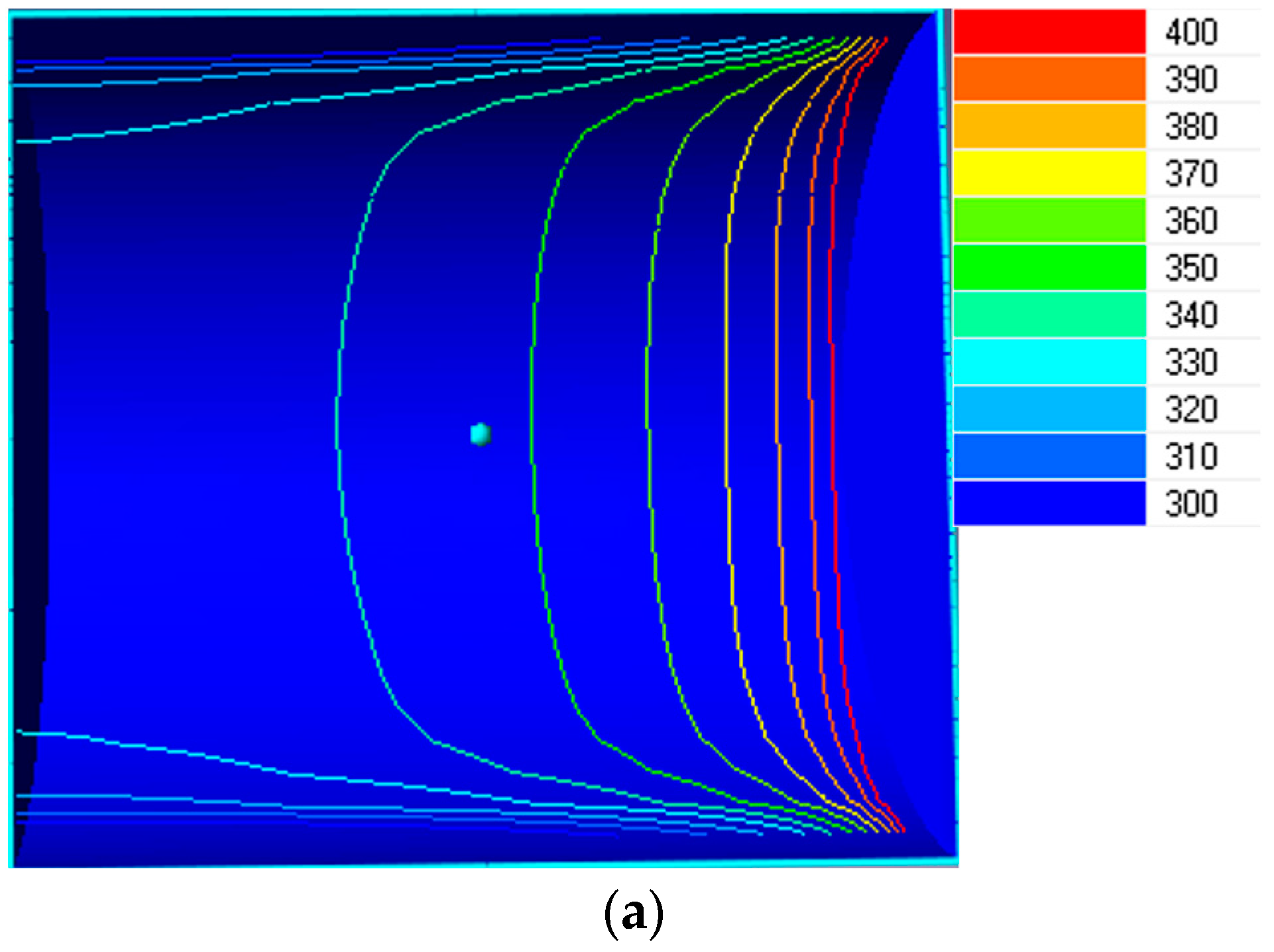
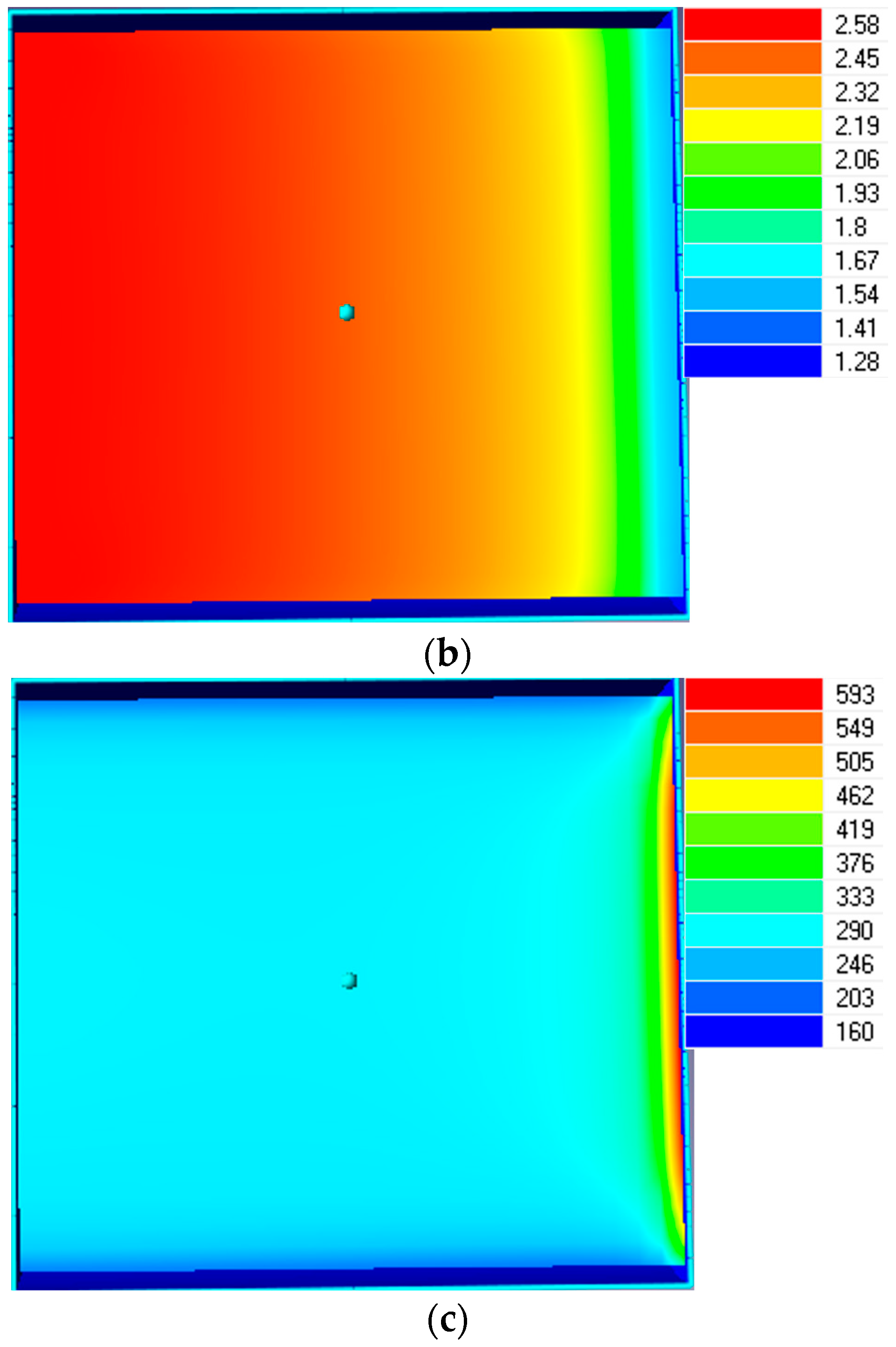
Visualization of the distribution of gas-dynamic parameters in the nozzle provides essential information that predetermines a need for change in the flow organization by a change in its geometry.
As an example, the numerical simulation results of the flow in the nozzle are presented in
Figure 8 and
Figure 9. These plots were built for different values of the nozzle diameter
d and unchangeable values of the length (
l = 22 mm) and pressure ratio
p1/
p2 = 1.98.
These visualizations show the distribution of abrasive flow parameters in the nozzle. Generally, they aim to understand flow organization and the effect of nozzle geometry on the flow. If vortices appear at certain operating parameters, it can be concluded how to influence the nozzle to improve its efficiency.
The difference in the flow structure of the working stream in nozzles with different values of the inner diameter draws attention. Particularly, for the case of d = 7 mm, non-uniformity of the flow parameters at the outlet from the nozzle was detected. However, this effect did not occur for higher diameters due to increased cross-sectional area. This effect did not also occur in the case of a single-phase flow.
Moreover, before the outlet cross-section of the nozzle, a blocking of part of the flow was detected. This was due to localized centers of increasing operating parameters. This effect also disappeared as the diameter increased.
The numerical simulation results were compared with the experimental results. The discrepancy was within 5%.
3.3. Choice of the Rational Geometry
After considering the peculiarities of the air–abrasive mixture flow in nozzles of various geometric parameters, additional studies were carried out to evaluate the rational design of the nozzle (
Table 2).
Table 2 demonstrates an increase in the flow ratio
μ with an increase in the nozzle diameter
d. This is because the mass flow rate of the abrasive mixture through the nozzle increases according to the continuity equation.
The average value of the ratio μ is about 1.0. However, variant 7 is the most rational. It has the highest value of the flow ratio of about 2.3. Nevertheless, in variant 5, a significant decrease in the nozzle length l up to 4 mm led to a significant increase in mass flow rate m of about 1.9 kg/s. This leads to increasing the mass flow rate of the mixture.
Overall, due to the rational choice of the geometric parameters of the abrasive jet device, the specific machining time decreased from 540 s to 120 s per unit of metal surface area. The energy efficiency of the corresponding compressor equipment also increased by 84%. The energy-efficient nozzle designs also confirmed their effectiveness on the experimental stand.
4. Discussion
From the analysis of the available types of nozzles for AJM, it can be concluded that the primary trend in the improvement of nozzles is the use of super-hard and wear-resistant materials (e.g., boron carbide [
31,
32], silicon carbide [
33], and tungsten carbide [
34]). These materials improve the performance characteristics of the nozzle and, accordingly, extend their durability. However, the new materials mentioned above are highly expensive. Moreover, there is loss in the energy efficiency of the corresponding compressor equipment during AJM.
Therefore, the rational choice of nozzle geometry was proposed to decrease the costs of nozzle design from available materials and increase the energy efficiency of the abrasive jet equipment. This reduced the hydraulic losses from the friction of the abrasive material with the walls.
The numerical simulation results for a two-phase flow through a nozzle agree with the research work by Van den Berghe [
9]. Particularly,
Figure 6 shows an increase in the mass flow rate with an increase in its diameter. This effect also corresponds to the research work by Sychuk et al. [
24].
The nature of the obtained approximation curves presented in
Figure 7 is explained by a disproportionate change in the operating characteristics of the nozzle to a change in its diameter. This fact also agrees with the research work by Xu et al. [
10]. The results can also be justified by [
15] because the rational choice of geometrical parameters significantly influences energy efficiency.
Moreover, the dependencies in
Figure 7 demonstrate the tendency to increase the flow ratio of the air–abrasive mixture in the nozzle and its mass flow rate with an increase in its internal diameter at constant pressure drop values. This result also corresponds to the research works by Li Aronson et al. [
11,
12].
The obtained results also allow for further improving the operating processes in jet apparatuses [
35] and modeling vortex chambers [
36].
5. Conclusions
The article presents the results of numerical and experimental studies of nozzles for AJM for variable geometric parameters. The research was carried out to find reserves in increasing the nozzle performance and ensuring the energy efficiency of abrasive jet equipment.
As a result, the difference in the working flow structure in nozzles with different inner diameters in a range of 7–20 mm was established. Particularly for the diameter of 7 mm, non-uniform flow parameters occurred at the outlet. Also, it was established that reducing the nozzle’s length to 4 mm significantly increases the mass flow rate.
The experimental studies and analytical approximations allowed for evaluating conditions to increase the energy efficiency of the abrasive jet equipment. Particularly, the machining time per unit of metal surface area was reduced by 4.5 times. Since the flow ratio predetermines the main parameters of the working nozzle and, consequently, the abrasive jet device, it was chosen as an efficiency indicator. Overall, the energy efficiency of compressor equipment for AJM was increased by 84%.
Thus, increasing the efficiency of the abrasive jet nozzle was realized by reducing the contact area of the working two-phase flow. Due to this, the friction of the abrasive material with the walls was reduced. As a result, AJM was accelerated, and the energy consumption of the corresponding compressor equipment was reduced. This made the nozzle more effective.
Further research directions will be aimed at improving the energy efficiency of AJM with porous nozzles.


