1. Introduction
The German Association for Electrical, Electronic & Information Technologies (VDE) has proposed organizing smart grids [
1] as a decentralized system composed of a hierarchy of spatial cells. In such a
cellular energy system, each cell has a certain level of autonomy to independently solve control deviations by applying flexibilities within itself.The goal is to create a common cellular concept that enables the rapid expansion of renewable energies without having to massively expand energy grids, while maintaining supply safety and voltage quality at least at today’s levels. A common concept is necessary, as first cells already exist and their numbers will increase in the future [
2,
3]. Existing cells are set up by companies and households that want to increase the self-consumption of energy from local PV using energy-management systems and storage units [
4].
Before standardizing and deploying cellular energy systems, the concept needs to be carefully studied for efficiency and resilience. The complex behavior of such a system can only be simulated, as it is impossible to build a full system with sufficient complexity for experiments [
5,
6,
7].
This paper investigates how cellular energy systems following the VDE approach can be simulated. To reuse existing high-fidelity models of energy system physics and communication, a co-simulation of these fundamentally different abstractions is required [
8]. A holistic simulation also requires integrating economic models (e.g., energy markets) with computationally intensive calculations, such as optimizations [
9].
The main contribution of this paper is, therefore, a new concept of a co-simulation framework. It employs the ICT simulator as a co-simulation master to reduce the execution time and configuration complexity. It applies proxies to abstract components in other domain-specific simulation models. The proposed co-simulation framework was evaluated with realistic scenarios representing cellular energy networks of different sizes. By measuring execution times in different configurations, potential bottlenecks of the co-simulator were identified. Furthermore, the impact of failures of a realistic, protocol-based communication on the energy system was shown, showcasing the feasibility of the proposed approach. Both the energy system and communication network are modeled in domain-specific simulators, enabling the comprehensive analysis of cellular energy systems via co-simulation at least 20 times faster than the real time for 111 households.
The paper is organized as follows.
Section 2 gives an overview of the respective VDE concept. The state of the art of the simulation and co-simulation of smart grids is given in
Section 3. The following section discusses requirements for the co-simulation of cellular energy systems. From these requirements, our concept is derived in
Section 5. A first co-simulator is presented in
Section 6, and the execution times are given in
Section 7.
Section 8 contains the results of this study.
2. Cellular Energy Systems
A cellular energy system, as defined by the VDE [
4], consists of cells that may contain smaller cells. A cell comprises networks, producers, consumers, and storage, and may include the electricity, gas, district heating, and even mobility sectors. It is orchestrated by a cell manager, which predicts and detects line congestion, applies flexibilities to avoid this, and may be able to operate the cell in an island mode in emergency cases.
Physically, energy networks are partitioned into a hierarchy of cells, of which one or several may belong to the same galvanically isolated network at a certain voltage (or pressure) level. A cell may contain subordinate cells whose networks are connected to it. As a result, cell sizes range from entire countries, as parts of the transmission network, to individual households or companies.
The cell manager orchestrates flexible producers, consumers, and storage within the cell in order to solve occurring control deviations and problems locally, if possible. Only if this is not sufficient are superior or neighboring cells requested to help (principle of subsidiarity). Therefore, cell managers and all other relevant components within a cell are connected via a secure communication path.
Voltage and frequency deviations within a cell are balanced by a three-stage process consisting of automatic stabilization, preventive network safety management, and market mechanisms. All available components participate to enable automatic stabilization by providing a primary reserve power and inertia based on the network frequency. Electric loads and inverters do this virtually, which stabilizes the network even in cases of communication failures and hacker attacks. Market mechanisms determine load flows when there is no overloading of resources (e.g., lines). Markets can be organized from international to intra-cell. Only if there is an immediate risk of overloading a resource, the cell manager intervenes with preventive network safety management. For this purpose, it assigns target values of active and reactive power to subordinate components and cells. The latter decide autonomously how to meet these targets using their available flexibilities, which replaces redispatch operations and allows to avoid load shedding.
3. Simulation of Energy Systems
In the literature, integrated simulation and co-simulation are two common options for the simulation of smart grids [
10]. The former approach relies on a standalone simulator that allows evaluating the entire system of interest. With co-simulation, multiple simulators are coupled, each simulating a model that describes a part of the system.
3.1. Integrated Simulation
The evaluation of energy systems on standalone power simulators is common. Tools such as Dymola, Matlab/Simulink and PowerFactory are frequently used to analyze electrical grids [
11]. Sector coupled-energy systems are also simulated in order to explore energy coupling and its effects on system decarbonization. An example is the TransiEnt library for the open modeling language Modelica that provides physical models for sector coupled-energy systems and is used to analyze energy coupling between electricity, heat, and gas [
12]. The concept of cellular energy systems introduced by VDE was also simulated in [
3], where only the physical model was implemented on a power dynamic simulator named Calliope. Due to the complexity of integrating events in a continuous simulator, analyzing information and communications technology (ICT) within cellular energy systems is not easily realized on standalone power simulators. Research has been performed on Modelica to transmit information packets between model components through techniques such as message passing communication (MCP) [
13]. However, the description of different message types implies major changes in the Modelica code, which reduces the portability of the solution.
Energy systems have also been simulated in communication network simulators to evaluate aspects such as communication protocols [
14] or to investigate failure scenarios and their consequences on the energy system resilience [
15]. The NS-2 network simulator was used to examine the bandwidth and latency needs for smart grid applications [
16]. To achieve this, the energy system modules were implemented in a high-level language such as C++ in order to be compatible with NS-2. This, however, becomes particularly difficult when the complexity of the energy system models increases. The use of energy system frameworks within network simulators simplifies the simulation of physical aspects of energy systems. Tong et al. applied this for the OPNET communication network simulator, in which the energy system simulation is an individual module in OPNET, called whenever a calculation of the physical system dynamics is required [
17]. Because of its single-threaded implementation, this method cannot handle simultaneous packet requests and therefore does not support scenarios where packets are sent by different agents at the same time.
Another approach is to design a new simulator that combines power dynamics, communication networks, and control systems. This method allows combining domain-specific models, regardless of their modeling paradigms. In addition to that, it provides simulations adapted to the desired scenarios, which results in realistic performance results. For example, SmartGridLab is an energy system simulator developed to allow evaluating new designs [
18]. Despite the promising results delivered, these types of simulators require considerable development time. In addition to this, they are difficult to reuse because they have been designed for specific scenarios [
10].
3.2. Co-Simulation
By combining domain-specific simulators, co-simulation supports the use of different simulation paradigms. Thus, multiple aspects of the energy system can be individually modeled by different experts. Two approaches are to be distinguished. In the first, standardized co-simulation interfaces are provided by domain-specific simulators to allow their integration into a master for coordination. In the second, domain-specific simulators are directly integrated into another domain-specific simulator.
3.2.1. Standardized Methods for Coupling Simulators
The use of co-simulation standards ensures a common simulation interface, thus improving interoperability. The most important ones are high-level architecture (HLA) and functional mockup interface (FMI).
HLA [
19] was designed by the U.S. Department of Defense for the simulation interoperability. It supports the development of simulation units (federates) that can be integrated to build a simulation. Sets of services, such as data transfer, synchronization and data exchange, are delivered by the HLA. Multiple HLA-based co-simulation applications for electrical smart grids were developed [
20,
21,
22]. Several combinations between different domain-specific simulators are also possible as shown in [
23]. The HLA comes with some challenges that must be considered. The first one consists in additional overhead caused by the communication between federates. Furthermore, HLA addresses only the solutions to technical interoperability (communication and time synchronization), while conceptual and functional aspects must be addressed by the designer [
23].
The FMI standard [
24,
25] defines an interface in the C language to be provided by domain-specific simulators for integration into a master, and for coordinating and exchanging intermediate values between the simulators. Domain-specific simulators are distributed in a file called functional mockup unit (FMU). It contains the implementation of the simulator as a dynamically loadable library or as C source code. It also contains the FMI model description, which specifies the intermediate values that may be exchanged. Masters can provide different control algorithms. In addition to the co-simulation, where the FMU contains an entire simulator, FMI also supports model exchange, where important parts of the simulator are provided by the master. Like HLA, FMI was also adopted in several scientific projects about the smart grid [
26,
27]. In [
9], FMI was proposed for coupling OMNeT++ with Modelica to perform a co-simulation of cellular energy systems. But FMI also has disadvantages. For example, supporting a C language interface imposes an additional requirement on simulation and modeling tools using different programming languages. Meeting such requirements may be expensive and time consuming [
23].
3.2.2. Customized Coupling Methods and Solutions
Using HLA or FMI ensures interoperability and scalability for co-simulation. However, in some cases, customized solutions are required to reduce the development time [
23]. These solutions are specifically adapted to application challenges and are implemented through the customization of coupling interfaces between simulators. On the other hand, this incurs the overhead of adjusting existing solutions to the new interface following the method involved. These custom methods are divided into three categories: multi-agent system approach (MAS), real-time approach and other solutions. The first two approaches are discussed in [
23]. Other solutions are also developed in order to allow the coupling of a cross-sectoral energy network. The Mosaik framework, based on the Python programming language, offers an application programming interface (API) in order to couple individual simulators [
28]. A communication protocol based on Transmission Control Protocol/Internet Protocol (TCP/IP) is provided to connect simulators in other processes. Several energy network simulations were performed with Mosaik [
29,
30].
SGSim [
31] is another co-simulation tool that uses OMNeT++ with Open Source Distribution System Simulator (OpenDSS) [
32], enabling the analysis of monitoring solutions within the energy system. A module implemented in OMNeT++ is coupled to OpenDSS, allowing the integration of physical properties of the energy network, such as state estimation and voltage monitoring, into the OMNeT++ communication simulator [
33].
4. Requirements for Co-Simulation of Cellular Energy Systems
As a concept with great relevance to society, cellular energy systems have to be carefully studied for efficiency and resilience before standardization and deployment at high costs. Co-simulation using available validated models is an obvious and appropriate approach for this purpose. However, it needs to be considered that large models are often required.
Resilience—one of the major claims of cellular energy systems—needs to be studied. In particular, the effects of errors, introduced through fault injection, should be analyzed. Errors can be failures of physical components (e.g., lines or generators), but also those of communication or IT systems. Erroneous regulation may be caused by excessively long or fluctuating latencies in the communication system or by deviations from the negotiated schedules of generators or loads. In addition, impacts on resilience caused by algorithms for markets and market aggregators should be analyzed.
Validated models have to be applied in simulations to obtain credible results. Many validated models exist in the field of smart grids; however, these are based on different paradigms. Communication protocols are generally simulated with event-based simulators, while models of the physics of energy systems are usually based on differential and algebraic equations solved with continuous simulation [
34]. Models for markets and market aggregators also require different paradigms for complex calculations and optimization, including machine learning [
35]. Combining all these so-called domain-specific models with their different paradigms to simulate the entire cellular energy system necessitates co-simulation.
The huge number of components in the interconnected energy networks leads to extremely complex models to be simulated. Components include power lines, transformers, generators, and prosumers with their PV systems, electric vehicles, controllable loads, etc. This makes the manual configuration of the different domain-specific simulators laborious and error-prone. Consistency between the latter is similarly difficult to achieve. Therefore, all simulators should be configured automatically from a single description of the energy system. Due to the high complexity of co-simulation, many variables have to be exchanged between the domain-specific simulators. The mapping between these variables across different simulators has to be automated. To reduce the simulation time, parts of the energy network can be replaced by simplified models that describe their behavior with sufficient accuracy, e.g., using machine learning [
35].
5. Co-Simulation Concept
In this paper, we propose a new concept for the co-simulation of cellular energy systems combining domain-specific simulators of an ICT, energy system, and dedicated models for cell managers, aggregators, and markets. Aggregators trade the consumption, generation, and flexibility of many small customers on markets. Proxies are introduced into the ICT model to represent components in other domain-specific models and to implement their communication capabilities. A common energy system description is used to consistently configure all domain-specific models.
5.1. Allocation of Components to Domain-Specific Models
All relevant properties of the cellular energy system have to be represented in one of the domain-specific models. Models should represent components from the real world to make them more comprehensible. The complexity of power system components ranges, for example, from cables to fuses, switches, energy meters, heat pumps, electric vehicles, and combined heat and power plants. In addition, there are components for communication and control, such as smart meter gateways, cell managers, aggregators, and energy markets. Interactions between components take place via energy and communication networks.
Each property must be concisely represented in one of the domain-specific models. Physical processes of components transferring and transforming energy including their interactions over energy networks are best modeled as complex differential equations. Such energy system models are commonly simulated as continuous, acausal simulations such that of the TransiEnt library [
12] for Modelica. In contrast, communication networks, including protocol stacks, are commonly modeled based on events (ICT models) for simulators such as OMNeT++ [
36]. Dedicated models may be required for specific properties involving complex computations (e.g., machine learning or optimization algorithms).
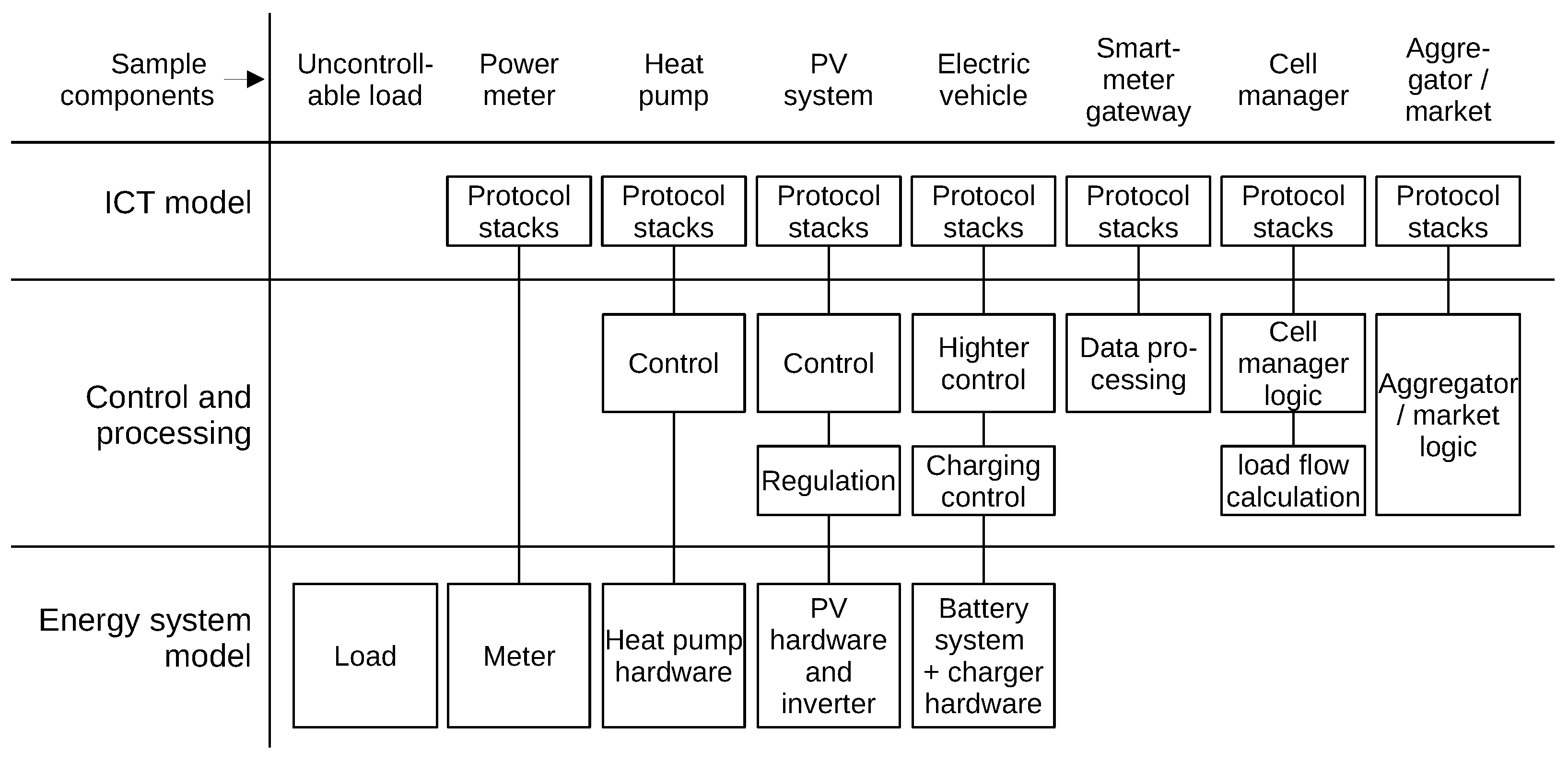
Components often involve properties best reflected in different domain specific models. For example, the communication of a heat pump belongs to the ICT model, while its physics is described in the energy system model. More examples are given in
Figure 1. Few components can be entirely described in the energy system or ICT model.
Some components have functions for controlling processes or extensive computations. These may be represented in the energy system ICT or dedicated models, depending on which representation is most concise. The data processing of a smart meter gateway belongs to the ICT model along with its communication protocols. Battery charging control close to physical processes of an electric vehicle (EV) might better fit the energy system model. However, a higher control of an EV for integration into household energy management might better fit the ICT model. Multiple layers of control can thus be represented in different models. Complex optimizations of cell managers, aggregators, and markets require specialized modeling techniques, while their communication should be represented in the ICT model.
In conclusion, the co-simulation concept in this paper assumes three types of domain-specific models. An energy system model for continuous simulation represents all physical processes including low-level control. An ICT model for event-based simulation represents communication protocols and other computations fitting to an event-based model. Cell managers, aggregators, and markets are represented in dedicated models based on languages for numerical computations, such as Python or Matlab.
5.2. Co-Simulation Options
Different options exist for connecting domain-specific models into a co-simulation (see
Section 3.2). Choosing an option requires selecting mechanisms for synchronization between domain-specific simulators via suitable interfaces. Frequently, a
master is used for coordination and to maintain a common clock. Synchronization is achieved through function calls from the master exchanging data between domain-specific models.
Considering its widespread use, FMI (see
Section 3.2) was chosen to integrate domain-specific simulators that must be provided as FMUs. While the generation of FMUs is supported by continuous simulators, including OpenModelica, Dymola, and Matlab/Simulink [
37], it is currently not supported by event-based simulators, such as OMNeT++. Nevertheless, there are frameworks to integrate FMUs with other domain-specific simulators. Mosaik [
38] enables the direct integration of Python-based simulators, FMUs (via libraries), and offers a JSON-based TCP/IP interface for all other simulator types. Continuous and event-based simulation are supported. As a master, Mosaik maintains common clock and triggers other simulators periodically, exchanging information between them. However, this approach conflicts with OMNeT++, which manages its own clock and calls procedures by itself upon events.
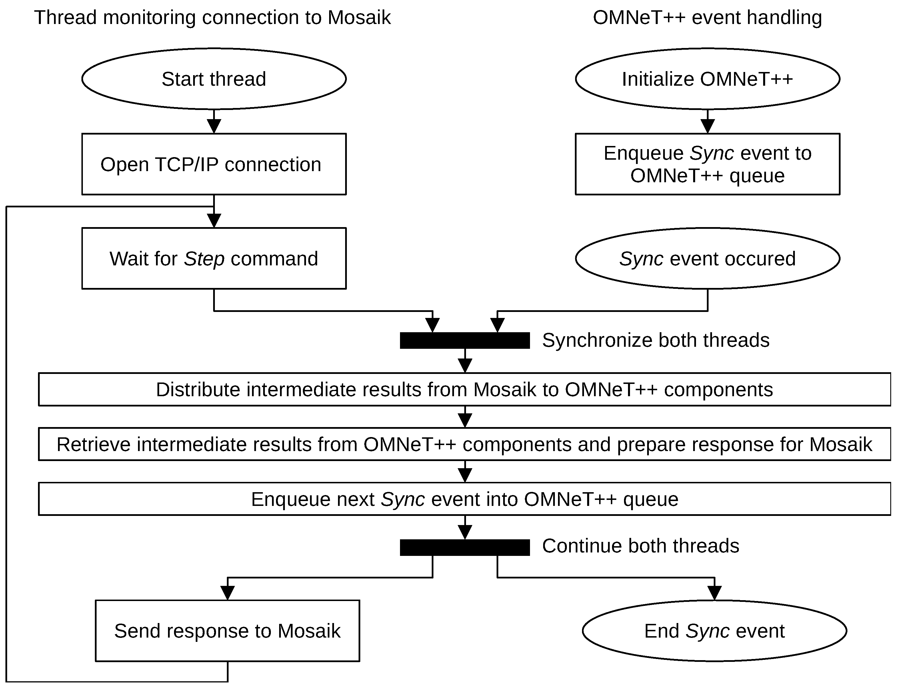
Generally, OMNeT++ can be integrated with Mosaik via a TCP/IP interface. Their clocks can be synchronized following the approach from
Figure 2. First, a
Sync event is scheduled by OMNeT++ for the simulation start time, and a thread connecting to Mosaik via TCP/IP is launched. The thread is blocked repeatedly, waiting for
Step commands from Mosaik, which instruct OMNeT++ to continue simulating for some interval
. To achieve clock synchronization, the thread executing
Step is blocked until the
Sync event occurs in OMNeT++. Likewise, the execution of
Sync is blocked until the
Step command is received. After both have occurred, relevant values are exchanged between domain-specific simulators and OMNeT++ components through Mosaik. Another
Sync event is scheduled by OMNeT++ to be executed in
time, when the next
Step will arrive from Mosaik. The thread and event scheduling in OMNeT++ continue to run concurrently, while the response is sent back to Mosaik, finishing the current
Step command.
For the co-simulation of cellular energy systems, it is only necessary to connect domain-specific components with their representations in the ICT simulator. Physical process interactions are simulated within the one energy system model, without Mosaik. All other interactions between power devices, cell managers, aggregators, and markets occur via the communication network. Thus, putting Mosaik in between representations of domain-specific models inside ICT simulator causes significant overhead.
To simplify co-simulation, the ICT simulator can act as a master instead of Mosaik, bringing a number of advantages. First, no synchronization of clocks is needed, as only the clock of OMNeT++ is used. Second, the communication among domain-specific simulators is simpler since they are interacting via the ICT simulator already. Third, integrating FMUs into OMNeT++ is straightforward by using their C interface. This also enables the ICT and energy system simulators to run in the same process, resulting in much faster interactions compared to the inter-process communication. However, additional effort is required to integrate simulators of cell managers, aggregators and markets, which can be achieved via TCP/IP. Finally, the independent development and reuse of existing domain-specific models is promoted.
5.3. Representing Components from Domain-Specific Models in the ICT Model
Any component using a communication network must be represented in the ICT model. For example, a generator with its physics modeled in the energy system model has its representation in the ICT model for communication with other components. To implement this concept in practice, a high-level abstraction is indispensable. We propose the use of proxy components [
39] in the ICT model to represent components already existing in other models. The proxy provides interfaces to other components in the ICT model and encapsulates the connection to its associated part in the other domain-specific model. Communication between components is thus achieved via their proxies in the ICT model.
Access from proxies to an FMU must be organized by a single component. Following the semantics of the FMI [
24], the simulation has to run some time between the set and read operations on variables. The correct sequence is to set variables, continue the simulation in the FMU, and then read the variables before attempting to set them again. This sequence cannot be guaranteed if proxies access the FMU directly in an uncoordinated manner. To ensure the correct ordering of operations, an FMI client component triggered by periodic events is necessary. This component needs to buffer variable values from the proxies to be set at the event. It also forwards variable values read from the FMU to corresponding proxies. For this purpose, the FMI client has an interface that allows proxies to set variables and to subscribe them for reading.
5.4. Consistency of Components and Networks in Domain-Specific Models
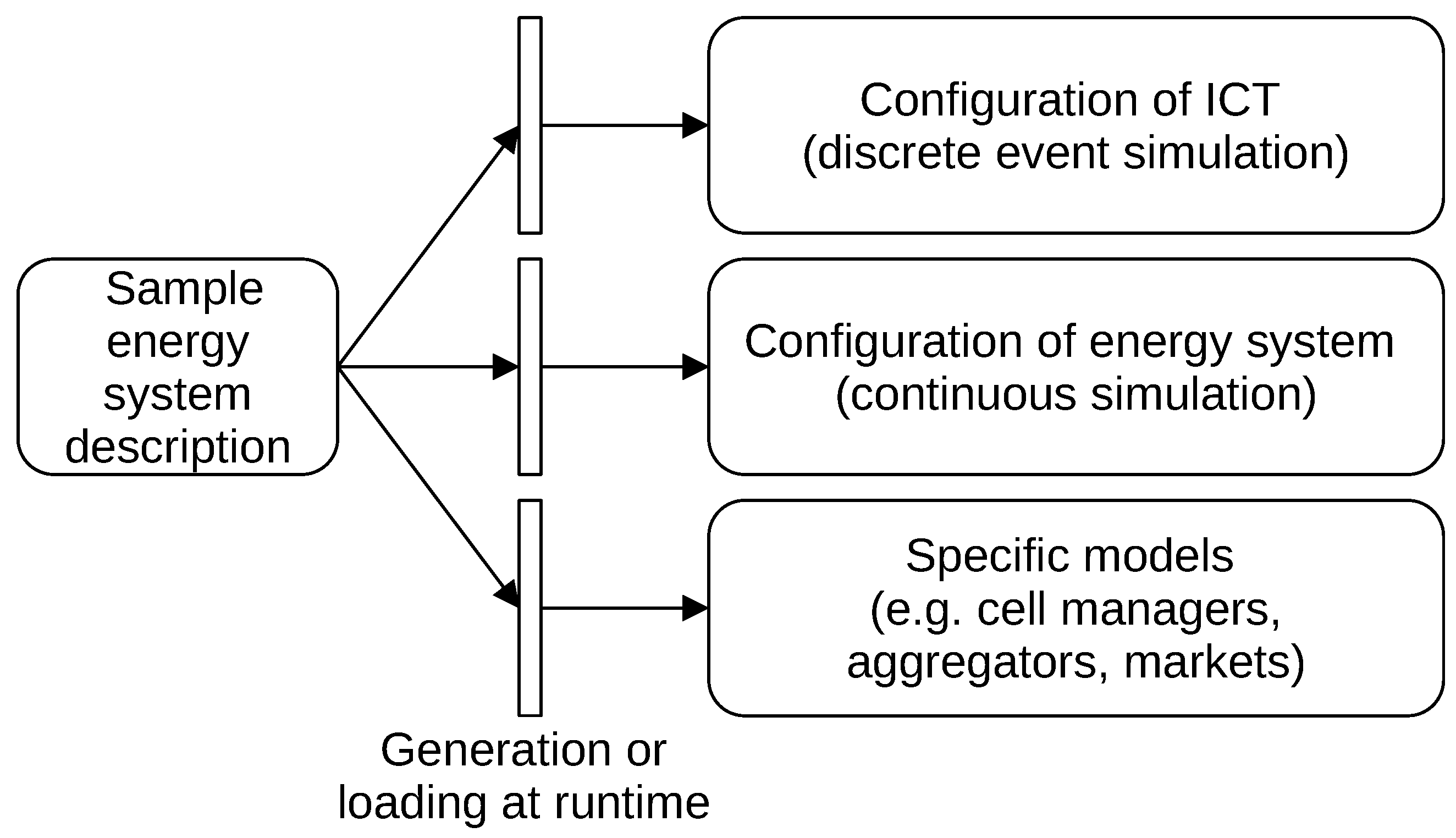
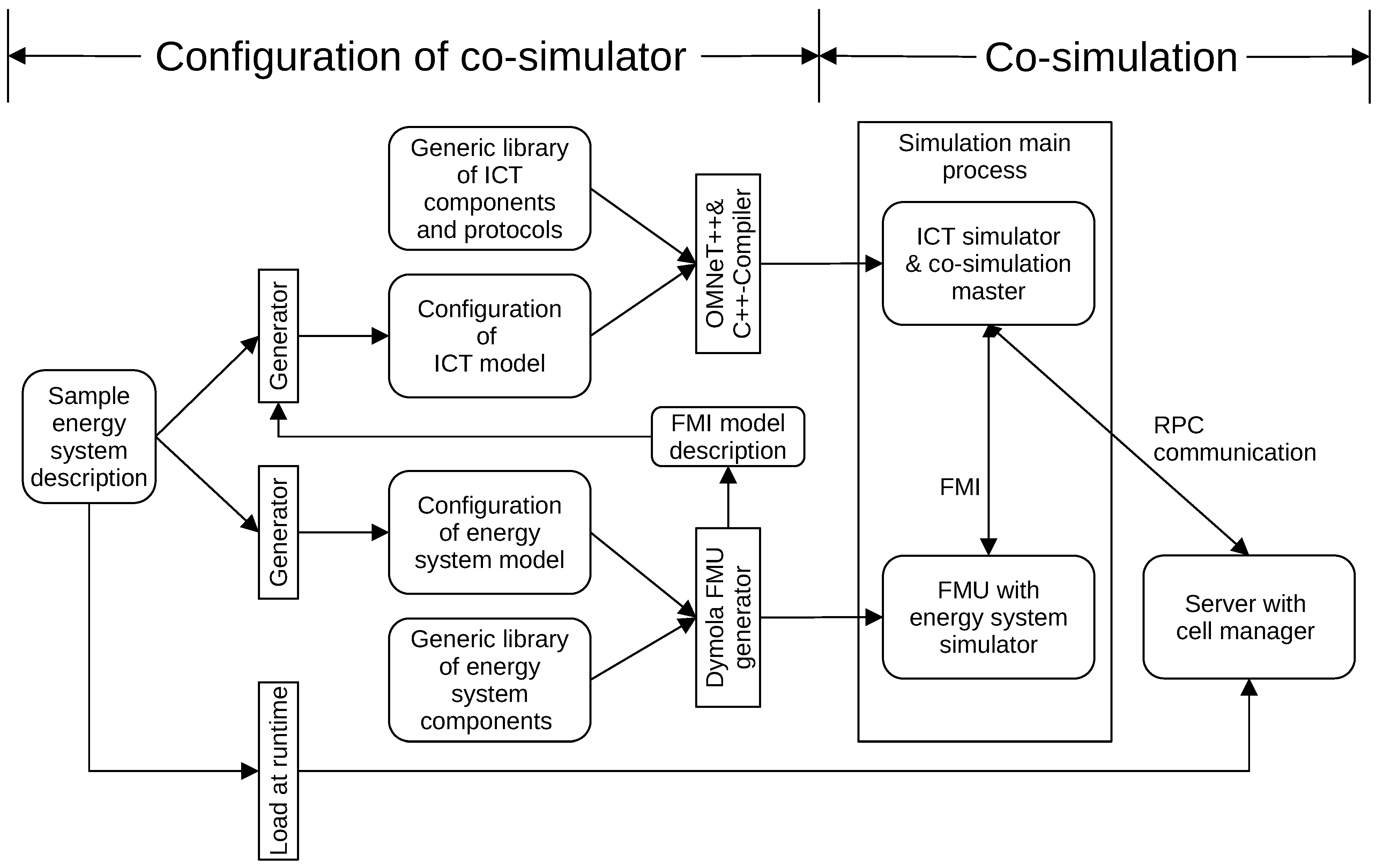
The cellular energy system must be consistently represented in all domain-specific models. This covers the existence and properties of all components, whose parts are represented in different models, including their assignment to cells and aggregators. Therefore, a common sample energy system description must be used for the configuration of all domain-specific models, as shown in
Figure 3. It must include details of all energy system components, e.g., power lines, gas and district heating pipes, together with their parameters. The energy system model can be generated from this description by instantiating components from a library, such as TransiEnt. The ICT model can be similarly configured based on the libraries of proxies, protocols and ICT components. The sample energy system description must also contain the assignment of entities to enable the configuration of cell managers, aggregators, and markets. Components belong to cells, households and generators to aggregators, cells and aggregators to markets.
The sample energy system description can be applied to a domain-specific model by generating model files at compile-time or by loading them at runtime. If models are compiled into a domain-specific simulator, generation at compile-time is the natural approach. Therefore, configuration files or source code for instantiating components is generated from the description. For models in highly dynamic languages, such as Python, loading at runtime is a suitable alternative. Components are then instantiated from a description after starting the simulator.
6. Implementation
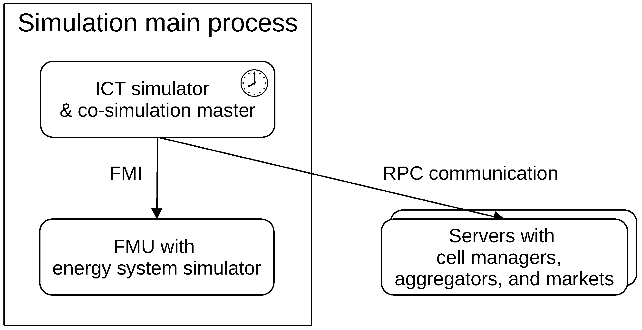
The co-simulation concept was implemented using OMNeT++ for the ICT model, Modelica for the energy system model, and Python for external servers of cell managers, aggregators, and markets. The ICT simulator serves as the co-simulation master, binding all other domain-specific models. The energy system model is included as FMU and cell managers, aggregators, and markets as RPC servers. The current implementation represents a single cell with 13 resp. 111 households and a cell manager available in two variants. The cell sizes were chosen because of the two available FMUs, modeling realistic low-voltage rural cells. Exploring further cell sizes requires conception and implementation of respective energy system models, which involves a development effort beyond the scope of this work. Future implementations will be extended to include several hierarchical cells with aggregators and markets.
The event-based simulator OMNeT++ was chosen for the ICT model because it has numerous ready-to-use libraries with communication protocol models, e.g., INET [
40] or Simu5G [
41]. The Modelica language is used to describe the energy system model because this enables the reuse of energy system components from the TransiEnt library. The models are simulated in Dymola [
42], which allows generating simulators together with numerical solvers as FMUs. As a master, OMNeT++ loads the FMU with the energy system simulator into the same process and interacts with it via the FMI. Models for cell managers, aggregators and markets are implemented in Python because it features libraries such as Pandas, Pandapower, and SciPy to solve numerical and optimization problems. Domain-specific simulators run in their own processes as servers. They are integrated into the co-simulation by a lightweight remote procedure call (RPC) mechanism.
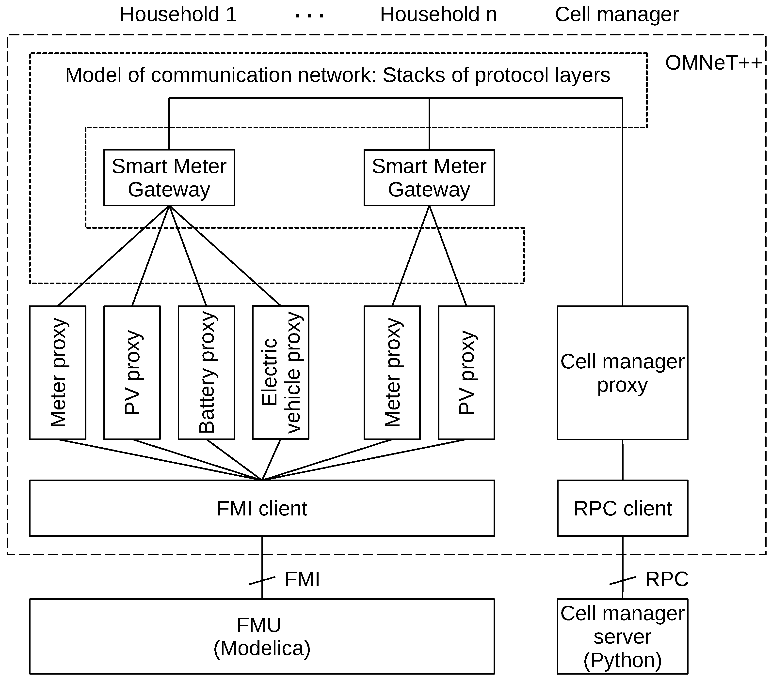
Figure 4 illustrates the overall co-simulation architecture.
To synchronize the different connected models, co-simulation works according to the client–server model. The co-simulation master calls domain-specific simulators periodically, instructing them to run their simulation for some time or to perform some calculations. Variables can also be set or read during these interactions, which are initiated only by the master. These function calls are also synchronous, i.e., the master waits until the callee has finished simulating. Hence, simulators do not run in parallel, which is intended to keep the implementation simpler and more manageable.
6.1. Component Architecture of the ICT Model
Proxies are used in the ICT model to integrate components from other domain-specific models. Households are modeled with their power devices that communicate with the smart meter gateway of the household. This gateway acts as communication hub and firewall, and communicates with the cell manager by sending aggregated meter data and by receiving commands.
Figure 5 gives an overview over the ICT model components. A proxy exists for each power device integrated into the ICT model. A proxy class was implemented for each type of device. Examples for power devices are PV systems, household batteries, and electric vehicles connected for charging. There is always a power meter measuring the active and reactive power of the household as well as voltage and frequency. Note that different households may contain varying types and quantities of power devices.
Communication between power devices and the gateway, as well as between gateways and the cell manager, can be abstracted by idealized channels of OMNeT++ to speed up simulation. These channels are configurable to simulate limited data rate, statistical loss of data, or occasional failures. Alternatively, a more realistic exchange of User Datagram Protocol/Internet Protocol (UDP/IP) messages over Ethernet was implemented, based on the INET library for OMNeT++. Future versions will include other communication protocols (e.g., wireless), as well as interactions between cell managers of different hierarchical levels (e.g., low- and medium-voltage cells), and with aggregators and markets.
6.2. Proxies of Energy System Components
Proxies representing energy system components connect to the FMU via an application-independent FMI client module as illustrated in
Figure 5. The FMI client loads the FMU and provides generic interfaces for the proxies to set and subscribe variables of interest. It periodically triggers the energy system simulation to run for some time, in synchronization with the OMNeT++ clock. The FMI client is a module in OMNeT++ which is instantiated once for every FMU. Being currently implemented for Windows, the FMI client loads the DLL containing the FMU simulator into the process of OMNeT++.
The FMI client sets a periodic timer event every
seconds of simulation time, at which it lets the FMU simulation continue. Only at these communication points are data exchanged with the FMU by reading and writing variables as is common for co-simulation with the FMI [
24]. The parameter
can be configured for an instance of the FMI client module. The FMI client provides an interface for proxies to set variables or to subscribe them for reading. The interface is based on abstracted messages sent over channels as common in OMNeT++. Subscribing to variables follows the common observer pattern from software architecture [
39]. During the initialization phase of the simulation, proxies subscribe to all relevant variables that represent the state of their counterparts in the energy system model. At each communication point, the FMI client forwards values of subscribed variables to the proxies. When a proxy wants to set a variable, the FMI client buffers the value until the next communication point.
The handling of variables shall be illustrated using a PV proxy as example. At simulation start, each PV proxy subscribes at the FMI client to variables of the corresponding PV system from the energy system model. These variables contain the amount of produced active and reactive power as well as the switch setting (on or off). At each communication point, the FMI client reads these variables from the FMU and sends them to the proxy. The proxy creates a packet with these values, adds identifiers of the proxy class and instance, and sends it to the respective smart meter gateway. In order to switch a PV system on or off, the smart meter gateway sends a packet to the proxy, containing a Boolean value. Upon packet reception, the proxy sets this variable in the FMI client that buffers the value and sets it in the FMU at the next communication point.
6.3. Proxy of the Cell Manager
The computation-intensive cell manager process was implemented in Python as standalone server. In OMNeT++, there is a proxy module representing the cell manager instance. The proxy implements the application layer communication protocol, i.e., ISO Open Systems Interconnection (OSI) Layer 7, and connects to the server via RPC. It is also responsible for controlling the cell manager temporally. For that purpose, it periodically calls the cell manager instance to perform computations and issue commands. This is necessary, as the cell manager is not aware of the clock and the event queue of OMNeT++. RPC access to the cell manager server is organized by an RPC client module that is instantiated once per server. It manages the TCP/IP connection to the server and provides generic method jsonRpcCall to initiate the RPC calls.
An RPC call transfers data bidirectionally, e.g., the cell manager gets readings of many meters as an input parameter in a request and returns target values for many power devices in a response. As a JSON message, the request is a list containing the procedure name, the current simulation time, as well as named and unnamed parameters. Both parameters and return values may be plain values or hierarchical JSON data structures, which enables calling arbitrary Python functions. It also allows transmitting structured data of arbitrary size with a single call, reducing the number of remote procedure calls and, consequently, the total execution time. Aggregators and markets will be implemented similarly.
In future versions, messages exchanged between cell managers, aggregators, and markets will be modeled as uninterpreted JSON strings in the ICT model, which simplifies the implementation. It also gives developers of cell managers, aggregators, and markets the flexibility to change message structures without having to adapt the ICT model. This sort of flexibility is very helpful during protocol development. However, to analyze bandwidth limitations, it may also be necessary to model packet formats provided by the ICT model in detail.
6.4. Configuration of Domain-Specific Models
The co-simulation is consistently configured based on a common energy system description stored in a relational database. The description is used to generate configuration files for domain-specific simulators, and is also loaded by the servers for cell managers, aggregators, and markets.
The sample energy system description models electricity networks as nodes with spacial locations connected by power lines of different types. Each node is part of a cell in some voltage level (e.g., 400 V). A household is a type of node with an uncontrollable load following a certain profile. Optionally, a PV system, a battery, or an electric vehicle may also be present. It is associated with an aggregator that belongs to a cell. Furthermore, different types of batteries, sensors, transformers as well as various weather conditions are modeled.
Figure 6 shows the configuration process for domain-specific models. The Modelica code modeling the energy system physics is generated based on a library of pre-developed components available in cellular energy systems. For the ICT simulator, a configuration file is generated, which is compiled by the OMNeT++ and C++ compilers along with additional libraries. The configuration file describes modules to be instantiated together with their settings. The modules are ICT components as well as proxies of components from the FMU and the cell manager. The generator needs the FMI model description from the FMU to configure the FMI client. This description contains variable identifiers to be used for read/write operations by the proxies. Lastly, experiment- and simulation-specific settings are defined, e.g., communication protocols configuration, simulation duration, and results collection.
The server for the cell manager implemented in Python loads its configuration from the energy system description in the database at runtime. The configuration is used to instantiate and configure the cell manager in the server process. In future implementations, loading at runtime could be replaced by generating program code for instantiation as is the case for the energy system and ICT model. Alternatively, a data file with the server configuration can be generated and loaded by the server at runtime, also eliminating the need to access the database.
7. Evaluation
The co-simulation framework was evaluated for its capability to implement a specific scenario focusing on the energy system performance. The execution time of each domain-specific simulator was analyzed to identify bottlenecks that might impede evaluation of large-scale scenarios with thousands of households. For this reason, two low-voltage, rural cells of different sizes, 13 and 111 households, were considered. Since an energy system requires the reliable and timely delivery of commands from the cell manager to households, a scenario was evaluated that shows the impact of communication network outages on the energy system.
7.1. Simulation Setup
The execution time was comparatively evaluated for two types of communication models, two types of cell managers, and two sizes of energy cells. For each simulation run, the energy cell was simulated for 2100 s. Runs were repeated 10 times with different random number generator seeds to evaluate the results with 95% confidence intervals. Simulations were performed on a Windows PC with Intel 11700KF processor and 32 GB of RAM.
The two types of communication models are an abstract model with idealized links, and a protocol-based one using UDP/IPv4 over Ethernet. The protocol models are taken from the INET library for OMNeT++.
The two versions of the cell manager are a simplified one sending static commands to charge or discharge batteries, and a cell manager running an optimal power flow (OPF) algorithm [
43]. The latter is a computation-intensive procedure, which uses linear optimization to minimize the total consumption from the medium voltage grid by employing batteries and renewable sources, while ensuring that power lines are not overloaded. Both cell managers receive measurements from household gateways and issue target values for the energy system every 60 s. According to the consumption profile of the electricity network, a control decision taken with 60 s periodicity is always able to prevent line overloads.
7.2. Impact of Cell Size on Execution Times
The relationship between the cell size (number of households) and the execution time of the co-simulation determines whether it is feasible to evaluate realistic large-scale scenarios using the proposed framework.
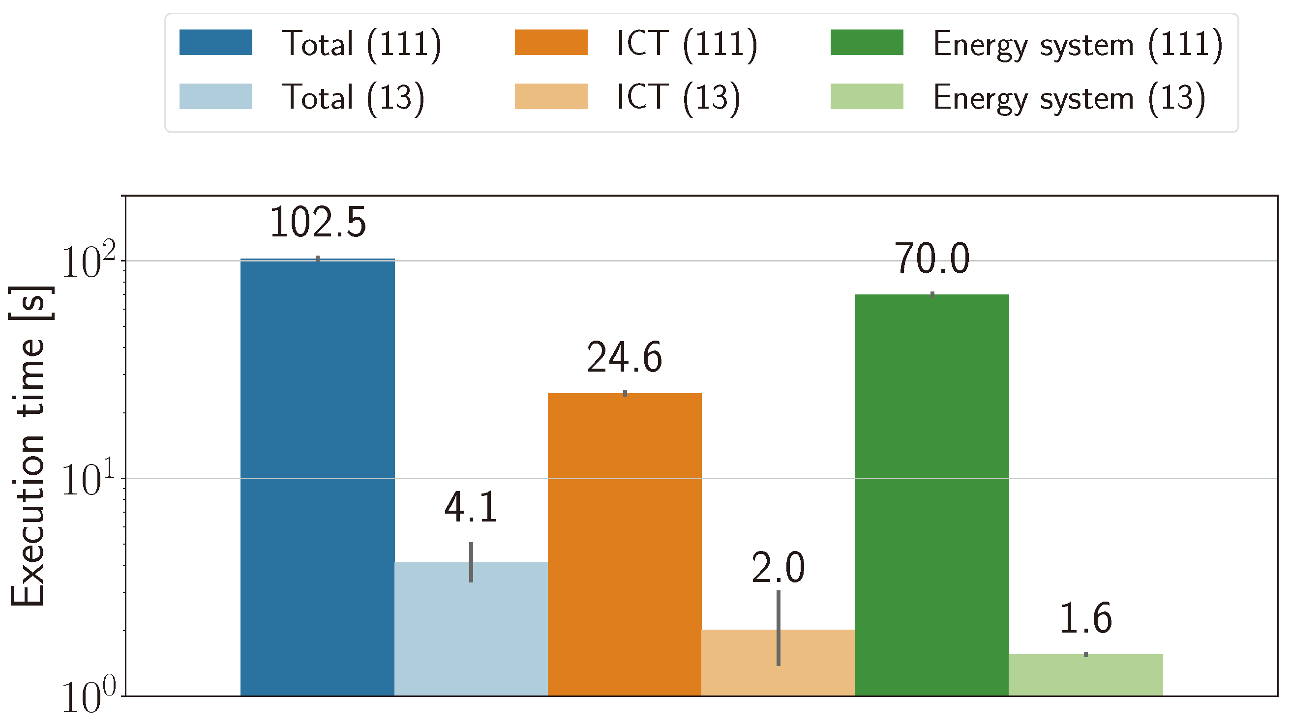
Figure 7 shows the execution time of the entire co-simulation along with the execution times of the ICT and the energy system simulation for the 13- and 111-household cell with protocol-based communication. ICT and energy system simulation consume the major share of the execution time. The remaining execution time of the cell manager is not shown in
Figure 7.
Simulating 111 households takes up to about 25 times longer than for 13 households, mostly due to the energy system simulation, which by itself takes about 43 times longer. Such an increase in the execution time is explainable by the higher number and complexity of the differential equations modeling household appliances. With more households, the load flow calculation produces larger Jacobian matrices that must be inverted to solve the system of equations, and the complexity of this operation rises more than linearly. The execution time of the ICT simulation is about 12 times longer for the larger cell, that is, it increases 36% faster than the number of households. A linear increase with respect to the number of households is caused by the higher number of packets exchanged within households, and between gateways and the cell manager. The increase beyond that is likely due to communication protocol models generating a number of events in OMNeT++ that grows faster than linearly with respect to the cell size.
7.3. Impact of Model Accuracy on Execution Times
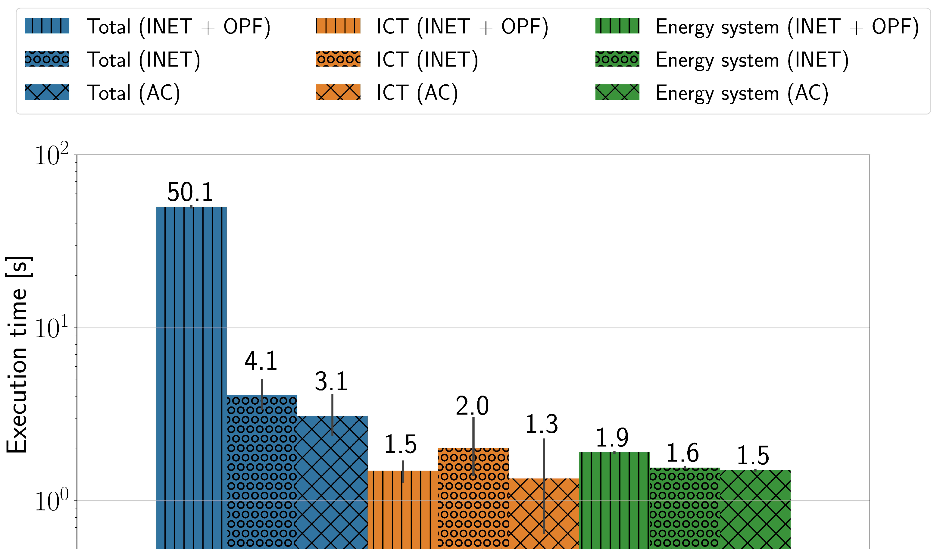
It is useful to have control over the accuracy of domain-specific models to balance the level of detail versus the execution time. In particular, the fidelity of one or several models can be sacrificed to focus on an in-depth, efficient analysis of the remaining ones. In the proposed co-simulation framework, the complexity of both the ICT and cell manager can be varied. We evaluated a number of configurations to determine the impact of model complexity on the total execution time of the co-simulation. From the simplest to most sophisticated, three configurations are considered:
Abstract communication (AC) with a simple cell manager.
Protocol-based communication (UDP/IP over Ethernet) using INET library.
Protocol-based communication with the cell manager running OPF, referred to as INET + OPF.
Figure 8 shows the execution times of the energy system and ICT simulation as well as the combined totals for each configuration. The execution time of the cell manager was omitted for conciseness but is discussed below. As visible from the figure for AC and INET configurations, without the OPF cell manager, the execution time is mostly spent on the energy system and ICT simulation. The ICT simulation also includes all operations performed by OMNeT++ as the co-simulation master.
Due to the small cell size (13 households), protocol-based communication is nearly as fast as the abstract one; hence, the total execution time of the INET and AC configurations do not differ significantly. However, as shown in the next subsection, depending on the sampling frequency, an almost twofold reduction in the execution time is possible when abstract communication is used instead of the protocol-based one.
The execution time of a simplified cell manager averages around only 0.5 s (AC and INET configurations), while the cell manager running the OPF algorithm occupies the largest chunk of the execution time with about 46 s (INET + OPF configuration). The simple cell manager consumes time almost only for the RPC calls, as only static charging/discharging commands are issued. On the contrary, the OPF cell manager is relatively slow since it involves linear optimization to determine the optimal set points for the energy network, thus increasing the total execution time up to 50 s.
7.4. Impact of Sampling Frequency on Execution Times
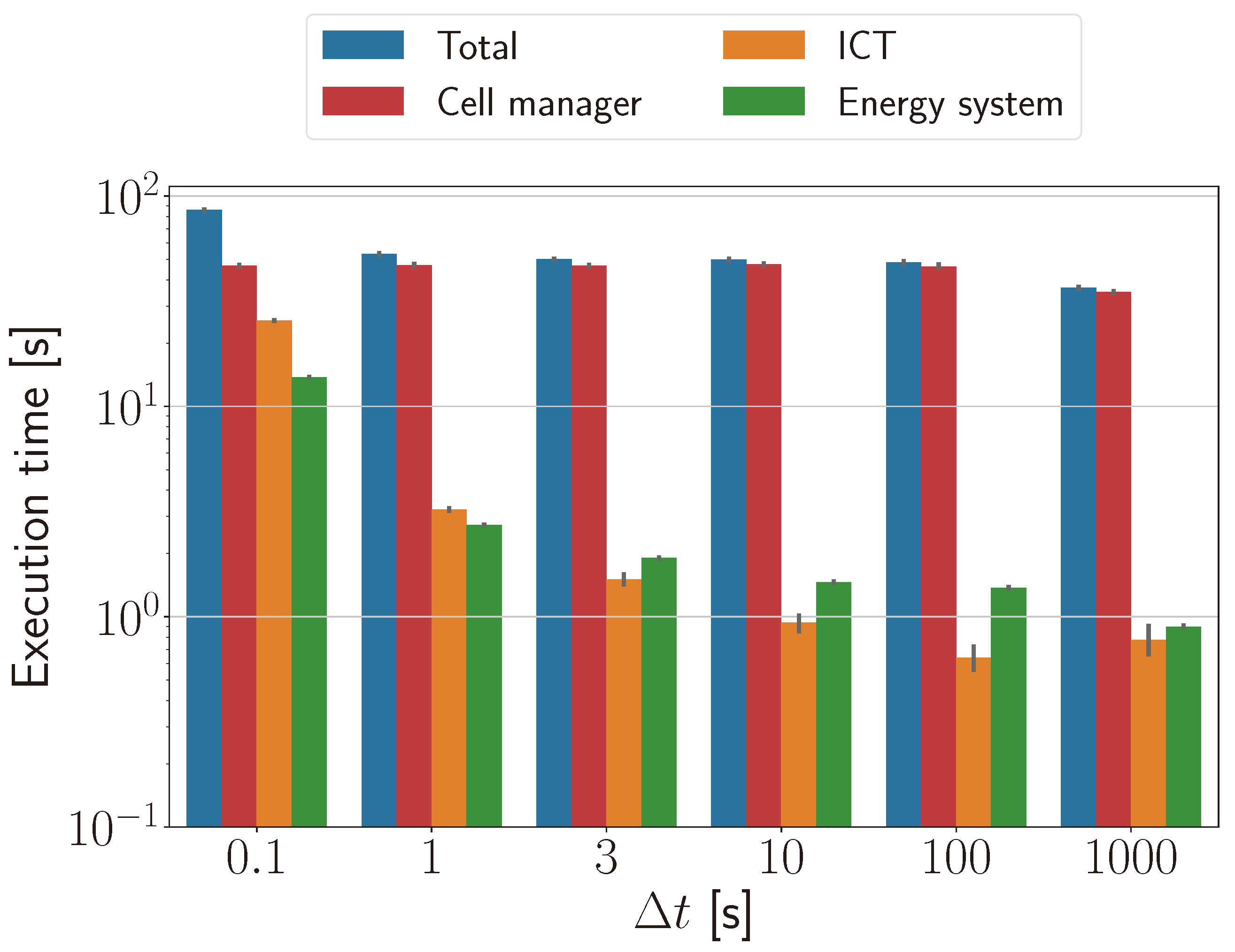
Another factor that determines the execution time is the length of the time intervals between communication points for exchanging values between the FMU (energy system simulator) and OMNeT++. Parameter defines how often values are read from the FMU and forwarded to household gateways. It can be viewed as a sampling rate of the energy system at the gateway. The appropriate value for depends on the required granularity of the energy system control by the cell manager. High values of will result in an outdated view of the energy system at the cell manager, leading to inefficient and unreliable control decisions. With low values of , the energy system can be operated with little to no lag at the cost of a higher traffic overhead generated by each household. In the previous subsections, 3 s was assumed to be an adequate value considering the 10 s periodicity of message exchanges between household gateways and the cell manager.
To show the impact of the sampling frequency, the 13-household cell was simulated for different values of
. The results are shown in
Figure 9. The cell manager performing optimal power flow calculation occupies the major portion of the total execution time, up to 54%. The execution time of the cell manager is not affected by
since the latter only influences the frequency of message exchanges between household devices and gateways but not between gateways and the cell manager. With a larger
, the execution times of the ICT and energy system simulations decrease non-linearly. Changing
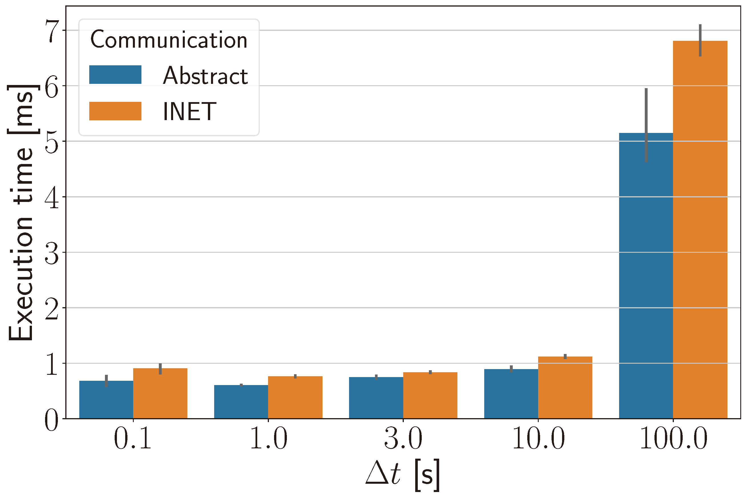
from 0.1 s to 1 s speeds up the energy system simulation by 80%, due to fewer function calls from the co-simulation master to the energy system FMU. Contrary to expectation, the cost of these calls also depends on
as shown in
Figure 10. The ICT simulation runs up to 88% faster with larger
due to the reduced number of packets being exchanged between proxies and the lower number of events generated inside the co-simulation master overall. Under a higher sampling rate with
0.1 s, more traffic is generated, and the execution time of an abstract ICT model is much shorter (9.4 s) compared to the protocol-based version (25.8 s).
7.5. Impact of Communication Failures on the Energy System
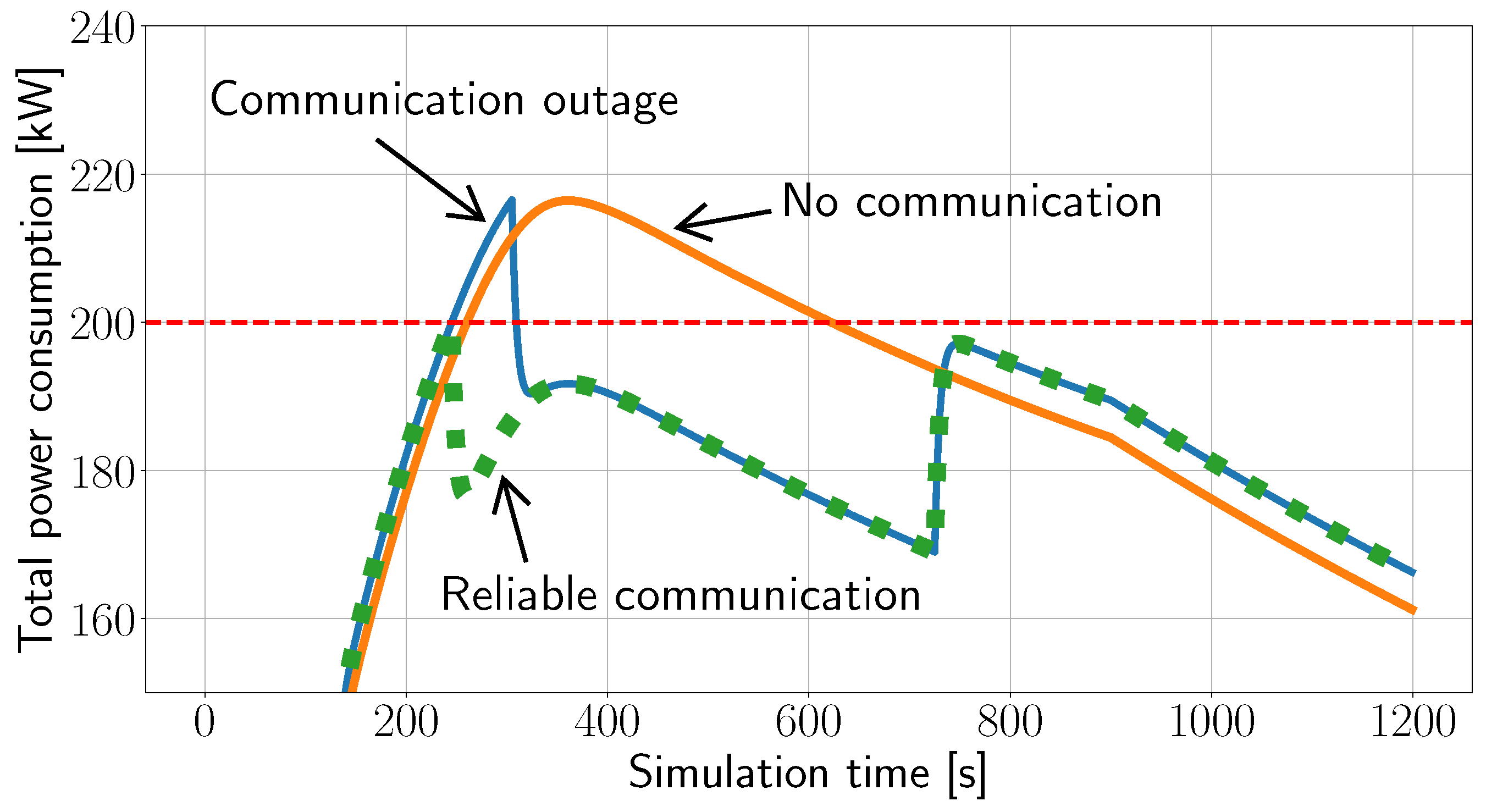
The models were used to analyze the impact of communication network outages on the energy system in a 111-household cell, proving the applicability of the co-simulation concept. As nearly each household has a battery electric vehicle (BEV), one of the cell manager tasks is to ensure that no electrical bus gets overloaded. The cell manager achieves this goal by controlling flexibilities in terms of household batteries and BEVs. In case a bus is likely to be overloaded, countermeasures are taken, e.g., by forcibly stopping the charging of BEVs or by reducing the charging power. However, the cell manager relies on the timely delivery of measurements from, and commands to, the energy system.
The example in
Figure 11 shows three cases, for which the maximum power of the substation bus is assumed to be 200 kW. Without cell manager intervention, i.e., if there is no communication at all, the continuous charging of 5 BEVs on top of the overall cell power consumption leads to an 8% overload on the bus for nearly 400 s. Having reliable communication and all measurements and commands delivered in time prevents the bus from being overloaded. This is achieved by the cell manager reducing the charging power of all 5 BEVs from 6 kW to 0.1 kW. However, if a communication outage occurs at the simulation time 240 s for the duration of 60 s, a cycle of the cell manager commands is lost. As a consequence, the bus gets overloaded again for the same percentage as without cell manager intervention but for a short duration only until the next exchange with the cell manager occurs one minute later.
7.6. Discussion
The evaluation shows the applicability of the proposed co-simulation framework for studying cellular energy systems comprised of several domain-specific models. Compared to the established co-simulator Mosaik [
44], our approach reduces the interaction overhead between the simulators by employing OMNeT++ as the co-simulation master. Detailed ICT simulation was not previously considered in Mosaik [
6,
28,
45,
46]. We show that coupling OMNeT++ with Mosaik [
47] can be avoided, provided that domain-specific simulators support FMI or RPC, and the development time should be minimized. Correlation between the size of the simulated energy network and the execution time of the co-simulation is important for understanding the feasibility of large-scale simulations, and has not been shown before. The limitation of our approach is that it is less flexible than Mosaik and is mostly beneficial if the effects of a
realistic communication network are to be analyzed. Furthermore, the event-based nature of OMNeT++ imposes challenges for the integration of models based on continuous-time simulation.
8. Conclusions
The analysis of cellular energy systems requires co-simulation that combines simulators of domain-specific models with fundamentally different abstractions into one simulation process. The approach successfully supports teamwork, as members can independently develop their models with the required abstractions. However, substantial effort is required to assemble the simulators. The effort can be reduced by configuring simulators for a specific energy system from one common description serving as single source of truth.
Using the ICT simulator as a co-simulation master has proven useful, as it reduces the complexity of the co-simulator and configuration as well as the overhead for interactions between simulators. Proxies in the ICT model simplify modeling the communication of components already defined in another domain-specific model.
Evaluation proved that impacts of communication failures on the energy system can be analyzed with the proposed co-simulator. Parts of distribution networks were simulated in reasonable time with realistic models of energy system and communication, both of which had similar CPU demands. The simulation of 111 households was about 20 times faster than real time. However, the execution time grew about twice as fast as the number of households, mainly due to the energy system model.
Future work includes testing the co-simulator on large-scale cellular energy systems to further identify potential bottlenecks and reliability issues. This may require simplified models of parts of the energy system to shorten the simulation time. Communication models should be extended to include wireless alternatives. Finally, using the proposed co-simulator, cellular energy systems can be studied for efficiency and resilience, as well as for economic and environmental impacts.
Author Contributions
Conceptualization, M.V. and V.T.; investigation, all; methodology, M.V., Y.S., T.S. and V.T.; resources, M.V., Y.S., A.Y. and T.S.; visualization, M.V., Y.S. and A.Y.; software, M.V., Y.S. and A.Y.; writing—original draft preparation, M.V., Y.S., A.Y. and T.S.; writing—review and editing and supervision, M.V., V.T. and C.B.; project administration and funding acquisition, V.T. and C.B. All authors have read and agreed to the published version of the manuscript.
Funding
The project CyEntEE is financed within the I3 program of the TUHH and the Hamburg Ministry for Science, Research, Equality and Districts (BWFGB).
Data Availability Statement
Acknowledgments
Publishing fees were supported by the Funding Program Open Access Publishing of Hamburg University of Technology (TUHH).
Conflicts of Interest
The authors declare no conflict of interest.
References
- Ekanayake, J.; Liyanage, K.; Wu, J.; Yokoyama, A.; Jenkins, N. Smart Grid: Technology and Applications; John Wiley and Sons, Ltd.: Chichester, UK, 2012. [Google Scholar]
- Kleineidam, G.; Krasser, M.; Reischböck, M. The cellular approach: Smart energy region Wunsiedel. Testbed for smart grid, smart metering and smart home solutions. Electr. Eng. 2016, 98, 335–340. [Google Scholar] [CrossRef]
- Flatter, F.; Mohammadi, S.; Wellssow, W.; Schinke-Nendza, A.; Blumberg, G.; Weber, C.; Rasti, S.; Schegner, P.; Uhlemeyer, B.; Zdrallek, M.; et al. ZellNetz2050—Structure, Planning and Operation of a Cellular Energy. In Proceedings of the ETG Congress 2021, Online, 18–19 March 2021; System in 2050. pp. 1–6. [Google Scholar]
- VDE Verband der Elektrotechnik. Zellulares Energiesystem—Ein Beitrag zur Konkretisierung des Zellularen Ansatzes mit Handlungsempfehlungen; VDE Verband der Elektrotechnik: Frankfurt am Main, Germany, 2019. [Google Scholar]
- Gabor, T.; Belzner, L.; Kiermeier, M.; Beck, M.T.; Neitz, A. A Simulation-Based Architecture for Smart Cyber-Physical Systems. In Proceedings of the 2016 IEEE International Conference on Autonomic Computing (ICAC), Wuerzburg, Germany, 17–22 July 2016; pp. 374–379. [Google Scholar]
- Steinbrink, C.; Blank-Babazadeh, M.; El-Ama, A.; Holly, S.; Lüers, B.; Nebel-Wenner, M.; Ramírez Acosta, R.P.; Raub, T.; Schwarz, J.S.; Stark, S.; et al. CPES Testing with mosaik: Co-Simulation Planning, Execution and Analysis. Appl. Sci. 2019, 9, 923. [Google Scholar] [CrossRef]
- Georg, H.; Müller, S.C.; Rehtanz, C.; Wietfeld, C. Analyzing Cyber-Physical Energy Systems: The INSPIRE Cosimulation of Power and ICT Systems Using HLA. IEEE Trans. Ind. Inform. 2014, 10, 2364–2373. [Google Scholar] [CrossRef]
- Gomes, C.; Thule, C.; Broman, D.; Larsen, P.G.; Vangheluwe, H. Co-Simulation: A Survey. ACM Comput. Surv. 2018, 51, 1–33. [Google Scholar] [CrossRef]
- Hoth, K.; Steffen, T.; Wiegel, B.; Youssfi, A.; Babazadeh, D.; Venzke, M.; Becker, C.; Fischer, K.; Turau, V. Holistic Simulation Approach for Optimal Operation of Smart Integrated Energy Systems under Consideration of Resilience, Economics and Sustainability. Infrastructures 2021, 6, 150. [Google Scholar] [CrossRef]
- Li, W.; Zhang, X. Simulation of the smart grid communications: Challenges, techniques, and future trends. Comput. Electr. Eng. 2014, 40, 270–288. [Google Scholar] [CrossRef]
- Vogt, M.; Marten, F.; Braun, M. A survey and statistical analysis of smart grid co-simulations. Appl. Energy 2018, 222, 67–78. [Google Scholar] [CrossRef]
- Dubucq, P.; Schmitz, G.; Andresen, L.; Kather, A.; Ackermann, G.; Peniche Garcia, R. Transientes Verhalten gekoppelter Energienetze mit hohem Anteil Erneuerbarer Energien. In Abschlussbericht des Verbundvorhabens; Technische Universität: Hamburg, Germany, 2017. [Google Scholar]
- Sanz, V.; Urquia, A. Cyber-physical system modeling with Modelica using message passing communication. Simul. Model. Pract. Theory 2022, 117, 102501. [Google Scholar] [CrossRef]
- Garlapati, S.; Volos, H.I.; Kuruganti, T.; Buehrer, M.R.; Reed, J.H. PHY and MAC layer design of Hybrid Spread Spectrum based smart meter network. In Proceedings of the 2012 IEEE 31st International Performance Computing and Communications Conference (IPCCC), Austin, TX, USA, 1–3 December 2012; pp. 183–184. [Google Scholar]
- Athreya, A.; Tague, P. Survivable smart grid communication: Smart-meters meshes to the rescue. In Proceedings of the 2012 International Conference on Computing, Networking and Communications (ICNC), Maui, HI, USA, 30 January–2 February 2012; pp. 104–110. [Google Scholar]
- Kansal, P.; Bose, A. Smart grid communication requirements for the high voltage power system. In Proceedings of the 2011 IEEE Power and Energy Society General Meeting, Detroit, MI, USA, 24–28 July 2011; pp. 1–6. [Google Scholar]
- Tong, X.; Liao, C. Co-simulation of OPNET-based wide-area communication in power system. Electr. Power Autom. Equip. 2010, 30, 134–138. [Google Scholar]
- Song, W.Z.; De, D.; Tan, S.; Das, S.K.; Tong, L. A wireless smart grid testbed in lab. IEEE Wirel. Commun. 2012, 19, 58–64. [Google Scholar] [CrossRef]
- IEEE. IEEE Standard for Modeling and Simulation (M&S) High Level Architecture (HLA)—Framework and Rules; IEEE Computer Society: New York, NY, USA, 2010. [Google Scholar]
- Molitor, C.; Groß, S.; Zeitz, J.; Monti, A. MESCOS—A Multienergy System Cosimulator for City District Energy Systems. IEEE Trans. Ind. Inform. 2014, 10, 2247–2256. [Google Scholar] [CrossRef]
- Zhang, Y.; Yao, Z.; Li, X. The Realization of OPNET and MATLAB Co-Simulation Based on HLA. In Computer, Informatics, Cybernetics and Applications Proceedings of the CICA 2011; Springer: Dordrecht, The Netherlands, 2012. [Google Scholar]
- Albagli, A.N.; Falcão, D.M.; de Rezende, J.F. Smart grid framework co-simulation using HLA architecture. Electr. Power Syst. Res. 2016, 130, 22–33. [Google Scholar] [CrossRef]
- Kazmi, J.H. Co-Simulation Based Smart Grid Communication Infrastructure Analysis. Ph.D. Thesis, Technische Universität Wien, Vienna, Austria, 2017. [Google Scholar]
- Modelica Association. Functional Mock-Up Interface for Model Exchange and Co-Simulation, version 2.02 ed.; Modelica Association: Linköping, Sweden, 2020. [Google Scholar]
- Blochwitz, T.; Otter, M.; Akesson, J.; Arnold, M.; Clauss, C.; Elmqvist, H.; Friedrich, M.; Junghanns, A.; Mauss, J.; Neumerkel, D.; et al. Functional Mockup Interface 2.0: The Standard for Tool independent Exchange of Simulation Models. In Proceedings of the 9th International Modelica Conference, München, Germany, 3–5 September 2012. [Google Scholar]
- Chatzivasileiadis, S.; Bonvini, M.; Matanza, J.; Yin, R.; Nouidui, T.S.; Kara, E.C.; Parmar, R.; Lorenzetti, D.; Wetter, M.; Kiliccote, S. Cyber-Physical Modeling of Distributed Resources for Distribution System Operations. Proc. IEEE 2016, 104, 789–806. [Google Scholar] [CrossRef]
- Galtier, V.; Vialle, S.; Dad, C.; Tavella, J.P.; Lam-Yee-Mui, J.P.; Plessis, G. FMI-based distributed multi-simulation with DACCOSIM. In Proceedings of the SpringSim, Alexandria, VA, USA, 12–15 April 2015. [Google Scholar]
- Schütte, S.; Scherfke, S.; Tröschel, M. Mosaik: A framework for modular simulation of active components in Smart Grids. In Proceedings of the 2011 IEEE First International Workshop on Smart Grid Modeling and Simulation (SGMS), Brussels, Belgium, 17 October 2011; pp. 55–60. [Google Scholar]
- Büscher, M.; Claassen, A.; Kube, M.; Lehnhoff, S.; Piech, K.; Rohjans, S.; Scherfke, S.; Steinbrink, C.; Velasquez, J.; Tempez, F.; et al. Integrated Smart Grid simulations for generic automation architectures with RT-LAB and Mosaik. In Proceedings of the 2014 IEEE International Conference on Smart Grid Communications, SmartGridComm 2014, Venice, Italy, 3–6 November 2014; pp. 194–199. [Google Scholar]
- Rohjans, S.; Widl, E.; Müller, W.; Schütte, S.; Lehnhoff, S. Co-Simulation of complex energy systems with Mosaik and FMI. Automatisierungstechnik 2014, 62, 325–336. [Google Scholar] [CrossRef]
- Son, S.; Kim, J.; Lee, S.; Park, S.; Jin Chung, B. SGSim: A unified smart grid simulator. In Proceedings of the 2013 IEEE Power & Energy Society General Meeting, 2013 IEEE Power & Energy Society General Meeting, Vancouver, BC, Canada, 21–25 July 2013; pp. 1–5. [Google Scholar]
- Xu, Y.; Alvarez-Fernandez, I.; Qu, Z.; Sun, W. Multi-Agent OpenDSS, An Open Source and Scalable Distribution Grid Platform. IEEE Smart Grid Bulletin, May 2021. Available online: https://smartgrid.ieee.org/bulletins/may-2021/multi-agent-opendss-an-open-source-and-scalable-distribution-grid-platform (accessed on 20 July 2023).
- Awad, A.; Bazan, P.; German, R. SGsim: A simulation framework for smart grid applications. In Proceedings of the 2014 IEEE International Energy Conference (ENERGYCON), Dubrovnik, Croatia, 13–16 May 2014; pp. 730–736. [Google Scholar]
- Schloegl, F.; Rohjans, S.; Lehnhoff, S.; Velasquez, J.; Steinbrink, C.; Palensky, P. Towards a Classification Scheme for Co-Simulation Approaches in Energy Systems. In Proceedings of the 2015 International Symposium on Smart Electric Distribution Systems and Technologies (EDST), Vienna, Austria, 8–11 September 2015. [Google Scholar]
- Balduin, S.; Westermann, T.; Puiutta, E. Evaluating different machine learning techniques as surrogate for low voltage grids. In Proceedings of the 9th DACH+ Conference on Energy Informatics, Sierre, Switzerland, 29–30 October 2020. [Google Scholar]
- Virdis, A.; Kirsche, M. (Eds.) Recent Advances in Network Simulation—The OMNeT++ Environment and Its Ecosystem; Springer: Cham, Switzerland, 2019. [Google Scholar]
- Modelica Association. Tools—Functional Mock-Up Interface. Available online: https://fmi-standard.org/tools/ (accessed on 20 July 2023).
- OFFIS e.V. Mosaik—A Flexible Smart Grid Co-Simulation Framework; OFFIS e.V.: Oldenburg, Germany, 2023. [Google Scholar]
- Gamma, E.; Helm, R.; Johnson, R.; Vlissides, J.M. Design Patterns: Elements of Reusable Object-Oriented Software; Addison-Wesley: Reading, PA, USA, 1995. [Google Scholar]
- Mészáros, L.; Varga, A.; Kirsche, M. INET Framework. In Recent Advances in Network Simulation The OMNeT++ Environment and Its Ecosystem; Springer: Cham, Switzerland, 2019; pp. 55–106. [Google Scholar]
- Nardini, G.; Sabella, D.; Stea, G.; Thakkar, P.; Virdis, A. Simu5G—An OMNeT++ Library for End-to-End Performance Evaluation of 5G Networks. IEEE Access 2020, 8, 181176–181191. [Google Scholar] [CrossRef]
- Brück, D.; Elmqvist, H.; Mattsson, S.E.; Olsson, H. Dymola for Multi-Engineering Modeling and Simulation. In Proceedings of the 2nd International Modelica Conference, Oberpfaffenhofen, Germany, 18–19 March 2002. [Google Scholar]
- Heuck, K.; Dettmann, K.D.; Schulz, D. Elektrische Energieversorgung: Erzeugung, Übertragung und Verteilung Elektrischer Energie für Studium und Praxis; Springer: Wiesbaden, Germany, 2013. [Google Scholar]
- Ofenloch, A.; Schwarz, J.S.; Tolk, D.; Brandt, T.; Eilers, R.; Ramirez, R.; Raub, T.; Lehnhoff, S. MOSAIK 3.0: Combining Time-Stepped and Discrete Event Simulation. In Proceedings of the 2022 Open Source Modelling and Simulation of Energy Systems (OSMSES), Aachen, Germany, 4–5 April 2022; pp. 1–5. [Google Scholar]
- Rohjans, S.; Lehnhoff, S.; Schütte, S.; Scherfke, S.; Hussain, S. mosaik—A modular platform for the evaluation of agent-based Smart Grid control. In Proceedings of the IEEE PES ISGT Europe 2013, Lyngby, Denmark, 6–9 October 2013; pp. 1–5. [Google Scholar]
- Farrokhseresht, N.; van der Meer, A.A.; Rueda Torres, J.; van der Meijden, M.A.M.M. MOSAIK and FMI-Based Co-Simulation Applied to Transient Stability Analysis of Grid-Forming Converter Modulated Wind Power Plants. Appl. Sci. 2021, 11, 2410. [Google Scholar] [CrossRef]
- Oest, F.; Frost, E.; Radtke, M.; Lehnhoff, S. Coupling OMNeT++ and Mosaik for Integrated Co-Simulation of ICT-Reliant Smart Grids. SIGENERGY Energy Inform. Rev. 2023, 3, 14–25. [Google Scholar] [CrossRef]
| Disclaimer/Publisher’s Note: The statements, opinions and data contained in all publications are solely those of the individual author(s) and contributor(s) and not of MDPI and/or the editor(s). MDPI and/or the editor(s) disclaim responsibility for any injury to people or property resulting from any ideas, methods, instructions or products referred to in the content. |
© 2023 by the authors. Licensee MDPI, Basel, Switzerland. This article is an open access article distributed under the terms and conditions of the Creative Commons Attribution (CC BY) license (https://creativecommons.org/licenses/by/4.0/).


 ,
, 