Article

Modeling of Specific Energy in the Gear Honing Process

1
School of Mechanical Engineering, Hefei University of Technology, Hefei 230009, China
2
College of Mechatronic Engineering, North Minzu University, Yinchuan 750021, China
3
Department of Mechanical Engineering, University of Kansas, Lawrence, KS 66045, USA
4
North Minzu University Library, Yinchuan 750021, China
*
Authors to whom correspondence should be addressed.
Energies 2023, 16(15), 5744; https://doi.org/10.3390/en16155744
Submission received: 6 July 2023 / Revised: 23 July 2023 / Accepted: 30 July 2023 / Published: 1 August 2023

Abstract

:
Gear honing is a cost-efficient method for the finishing of hardened gears in which material removal is realized through honing wheel and workpiece gear interactions. There are a number of indicators used for evaluating the degrees of these interactions, among which specific energy is a more appropriate one than the others since it is capable of quantifying the amount of energy consumption during the material removal process. Nevertheless, models for the prediction of specific energy in gear honing have not been thoroughly investigated. This work presents a theoretical model of specific energy to quantitatively evaluate the material removal efficiency in the external gear honing process. To develop the model, an analytical material removal rate and a honing force model are proposed, and the feasibility of the proposed model is validated against external gear honing experiments. The correlations of specific energy with processing parameters are investigated and the material removal efficiency scores of external gear honing and grinding are compared and discussed. The present approach enables an in-depth understanding of the abrasive–material interactions in the gear honing process and the effects of processing parameters on material removal efficiency.

1. Introduction

Gear honing is usually used in the precision machining of hard finish gears due to its ease of operation, low noise, and smooth performance [1,2]. Therefore, it is typically used as the final gear finishing process to improve the sound characteristics and lifespans of hardened gears. The performance of gear honing is typically evaluated by honing force [1], surface roughness after honing [3], the geometry of abrasive grains [4,5], and the fracture of abrasive grains [6]. However, none of these parameters can quantitatively measure the honing efficiency in the honing wheel and workpiece gear interaction process. Defined as the energy expended per unit volume of material removed, specific energy is an important performance parameter for characterizing the machining process [7] and is capable of quantitatively measuring the material removal efficiency of a workpiece [8]. Therefore, specific honing energy may act as an important supplement in the evaluation of gear honing efficiency. Although researchers have developed many specific energy models for various machining processes, few of them may be used to predict specific energy in the honing process.
Gear honing can be regarded as a low-speed grinding process since it has similar material removal characteristics with grinding [9]. Therefore, the development of specific honing energy may refer to the modeling process for specific grinding energy. Malkin [10] reported a specific grinding energy model that consists of specific chip formation energy, specific sliding energy, and specific ploughing energy. Then, Singh and Ghosh et al. [7,11] further pointed out that specific energy includes energies consumed in chip formation, primary rubbing, secondary rubbing, and the ploughing of the workpiece. It worth noting that the above models were developed based on single-grain experiments. Gear honing is a complex spatial multi-tooth engaging transmission, and the interaction between the honing wheel and workpiece gear is a multi-grain grinding process. Hence, the modeling of specific honing energy is more complicated than that based on the single-grain model. Ren. et al. [12] modeled the specific energy involved in the grinding of tungsten carbides from a macro perspective by considering various grain sizes and constructed a mathematical model from the macro perspective; this is a multi-grain model and can be easily validated experimentally. From the macro-scale perspective, the specific energy models for multi-grain grinding processes are typically represented by the ratio of grinding power and material removal rate [13,14,15], despite their various requirements. Hence, the challenges of specific energy modeling may rest on the determination of honing force and material removal rate.
In this regard, Bergs [1] formulated a honing force model for the internal gear honing process by simplifying the complex honing process into an equivalent grinding process, which was proven reliable when comparing the calculated values with the experimental ones. Moreover, there are mainly three approaches to determine material removal rate. The most popular one is defined as the product of cutting the cross section and the grinding speed [10,16,17,18]. The second is from a microscopic point of view: firstly, the volume of material removed by a single abrasive is derived, and then, the number of active abrasive grains participating in cutting is estimated to find the number of chips produced per unit time, whereby the product of the two is the material removal rate [19,20]. In the third one, the material removal rate is derived by calculating the weight of material removed per unit time [21,22]. As the spatial motion of the gear honing process is rather complex, and there is more than one tooth engaged in cutting at the same time, its material removal cross-sectional area, the number of active abrasive grains, and the weight of material removed are hard to be obtained. Therefore, the above methods no longer suitable.
In this study, an analytical material removal rate and honing force model for predicting the specific energy in honing of hardened gear are proposed. The feasibility of the proposed model is validated against external gear honing experiments. The discussion of the validation results and the effects of honing parameters on specific honing energy are presented at the end.

2. Modeling of Specific Honing Energy

Specific energy, e s , is an important parameter that can be used to identify the mechanisms of abrasive–workpiece interactions, and it is defined as the energy expended per unit volume of material removal, which can be represented as below:
e s = P Q w
where P is the honing power associated with the honing force and cutting speed and Q w is the material removal rate.

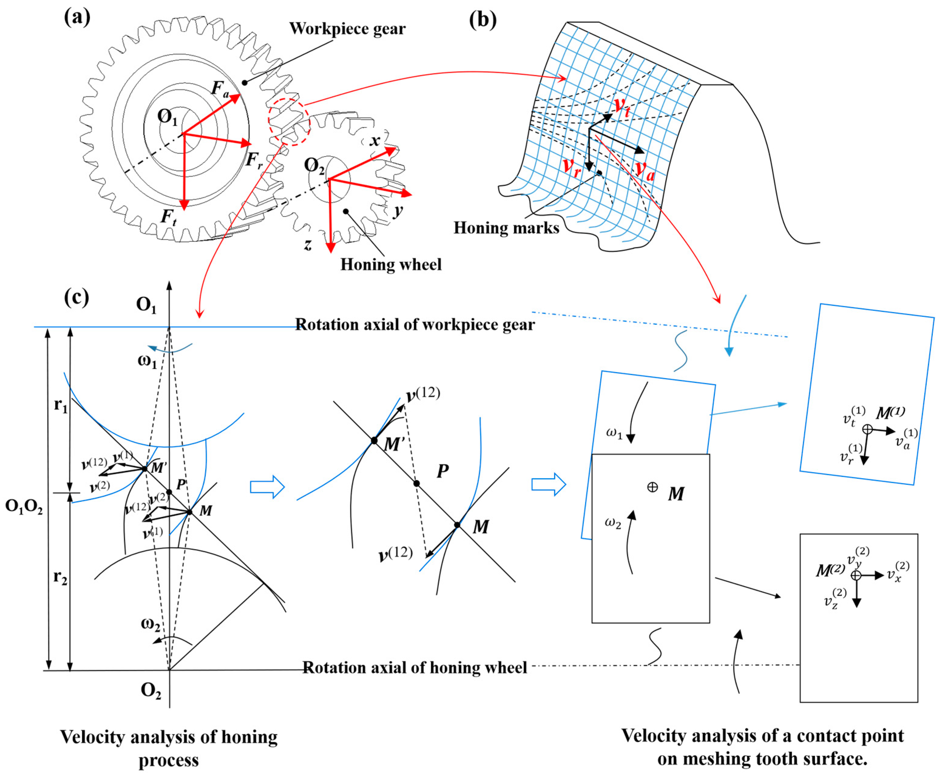
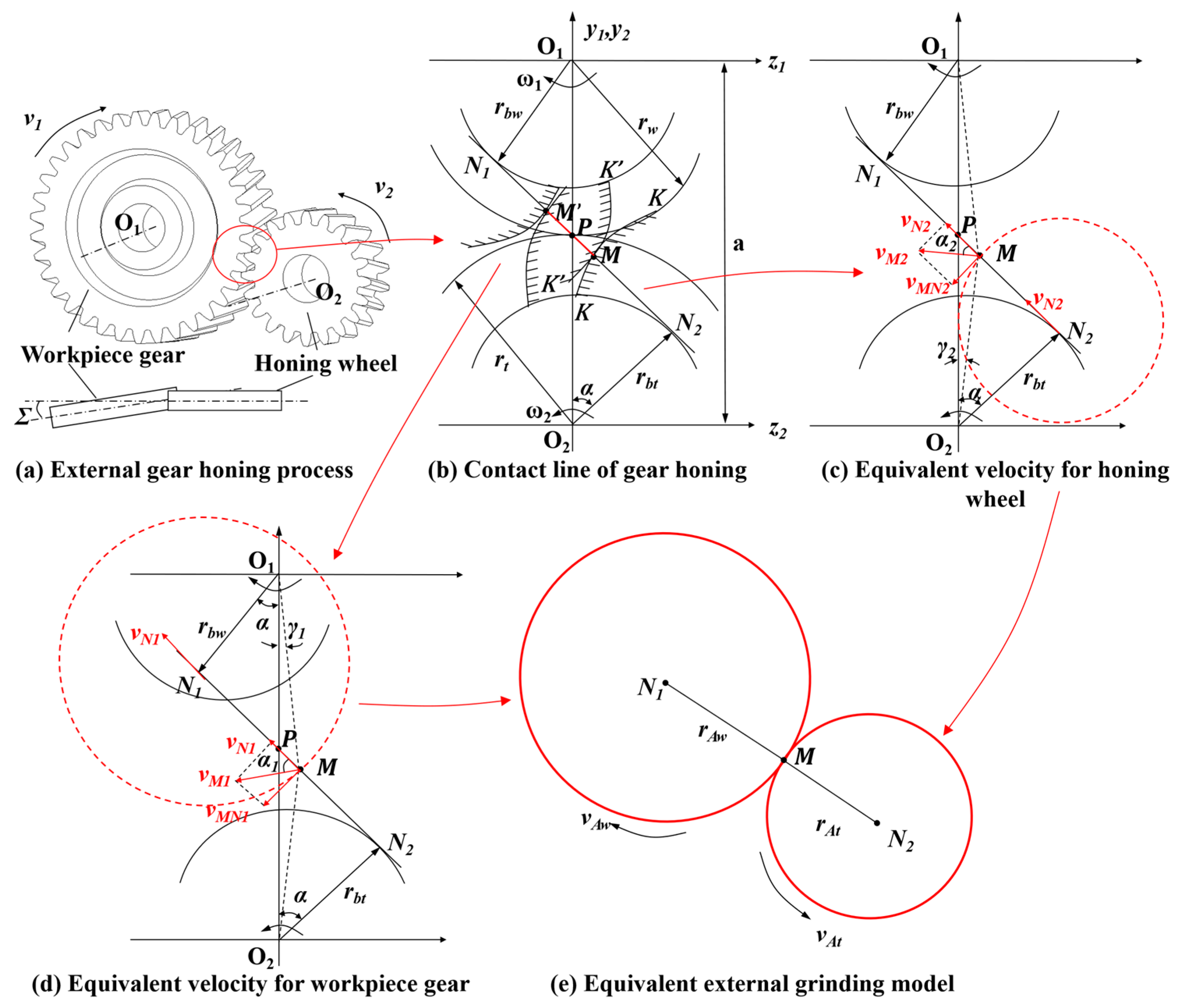
2.1. Modeling of Honing Power

The external gear honing process is shown in Figure 1a, where F a ,   F r ,   and   F t are the honing force components in the coordinate system of the workpiece gear and denote the coordinate system of the honing wheel. The honing power in Equation (1) associated with the honing force components can be written as below:
P = F · v ( 12 )
where v ( 12 ) is the relative velocity between the workpiece gear and honing wheel and F is the force vector of the workpiece gear, which can be expressed as follows:
F = F t · t + F r · r + F a · a
Figure 1b depicts the honing marks on the tooth surface of the workpiece gear, and v a ,   v r ,   and   v t are the components of relative velocity v ( 12 ) in different directions, which can be written as below:
v ( 12 ) = v ( 1 ) v ( 2 ) = v t ( 12 ) t + v r ( 12 ) r + v a ( 12 ) a
where v t ( 12 ) , v r ( 12 ) ,   and   v a ( 12 ) are the projections of v ( 12 ) in the circumferential, radial, and axial directions, as shown in Figure 1c, which can be represented as follows:
    v t ( 12 ) = | v t ( 1 ) v t ( 2 ) | ,   v r ( 12 ) = | v r ( 1 ) v r ( 2 ) | ,   v a ( 12 ) = | v a ( 1 ) v a ( 2 ) |
where v a ( 1 ) ,   v t ( 1 ) , and v r ( 1 ) are the velocity components of point M(1) on the workpiece gear and v a ( 2 ) ,   v t ( 2 ) , and v r ( 2 ) are the projections of the velocity components v x ( 2 ) , v y ( 2 ) , and v z ( 2 ) of point M(2) on the workpiece gear onto the coordinate ( a , t , r ), which read as follows:
v a ( 2 ) = v x ( 2 ) c o s Σ ,   v t ( 2 ) = v y ( 2 ) ,   v r ( 2 ) = v z ( 2 ) c o s Σ
During the gear honing process, when the honing wheel rotates against the axis and moves along the axial directions, suppose that there is no radial feed rate. Therefore, v x ( 2 ) = v a , v y ( 2 ) = ω 2 ρ 2 , and v z ( 2 ) = 0 . Meanwhile, the workpiece only rotates against its axis, and hence, v a ( 1 ) = 0 ,   v t ( 1 ) = ω 1 ρ 1 , and v r ( 1 ) = 0 . ρ 1 and ρ 2 are the distances from points M(1) and M(2) to their rotational axes. Substituting Equation (6) into Equation (5), we get the following:
    v t ( 12 ) = | ω 1 ρ 1 ω 2 ρ 2 | ,   v r ( 12 ) = 0 ,   v a ( 12 ) = v a c o s Σ
It is worth noting that points M(1) and M(2) are contact pairs wherein the values of velocities are equal, i.e., ω 1 ρ 1 = ω 2 ρ 2 . Thus, Equation (7) can be rewritten as
    v t ( 12 ) = 0 ,   v r ( 12 ) = 0 ,   v a ( 12 ) = v a c o s Σ
Therefore, by combining Equations (2)–(4) and (8), the honing power can be expressed as below:
  P = F a · v a c o s Σ
In Equation (9), the axial feed velocity v a and cross-axial angle Σ are known in advance; therefore, the honing force component F a needs to be further determined below.

2.2. Modeling of Honing Force

The external gear honing process may be simplified as an external grinding process, as shown in Figure 2. Figure 2b shows the contact line of the honing wheel and workpiece gear, where O 1 , O 2 and r b w , r b t denote the rotational centers and the radii of the base circles of the workpiece gear and honing wheel, respectively; α and ω 1 , ω 2 represent the pressure angle and angular velocities of the honing wheel and workpiece gear; O 1 P = r w and O 2 P = r t with regards to the radii of pitch circles; M M is the contact line of the gears. Figure 2c depicts the equivalent method for the velocity of contact point M on the honing wheel. The contact line M M is a tangent to the base circle of the honing wheel at N2, and γ 2 is the angle between lines O 2 M and O 2 P . Let v N 2 be the velocity of point N2 rotating around point O2; then, according to the kinematic method, with N2 as the base point, the velocity of contact point M can be expressed as the vector sum of v N 2 and the velocity of M relative to N2, which reads as below:
    v M 2 = v N 2 + v M N 2
Therefore, the value of v M N 2 can be determined thus:
v M N 2 = v N 2 t a n α 2 = ω 2 r b t t a n ( α γ 2 ) = π n t · r b t t a n ( α γ 2 ) 30
As shown in Figure 2c, the angle γ 2 is much smaller than α ; hence, for simplicity’s sake, γ 2 can be eliminated from the above equation and the resulting error may have little effect on the overall calculation results. As such, the above equation can be written as follows:
v M N 2 π n t · r b t t a n α 30
Similarly, as shown in Figure 2d, we can obtain the following:
  v M N 1 = v N 1 t a n α 1 = π n w · r b w t a n ( α γ 2 ) 30 π n w · r b w t a n α 30
Drawing circles with the radii of N 1 M and M N 2 , we can obtain the equivalent external grinding model as shown in Figure 2e, where the equivalent velocities and radii of the workpiece and honing wheel can be represented in the following forms:
  v A t = v M N 2 ,     v A w = v M N 2 r A w = M N 1 = r b w t a n ( α + γ 1 ) r b w t a n α r A t = M N 2 = r b t t a n ( α γ 1 ) r b t t a n α
According to T. Burgs [1], the normal equivalent honing force F n can be determined by the relation below:
F n = k · l Σ · b · ( v a v A w v r d e q ) a
where k and a are empirical constants, l Σ is the contact length, b is the analogy linear rotation velocity of the workpiece gear, and d e q is the equivalent grinding wheel diameter.
The contact length l Σ may be expressed as below [1]:
l Σ = a p d e q c o s ( Σ )
The equivalent grinding wheel diameter d e q may be represented as below:
d e q = d A t d A w c o s Σ d A t c o s Σ + d A w
Honing force is related to parameters such as feed rate, axis intersection angle, depth of cut, and rotational speed, and changes in the radial feed rate will induce changes in the depth of cut. In this paper, assuming that the radial feed speed is zero, and given an initial depth of cut a p , the equivalent circumferential force F t , radial force F r , and axial force F a can be represented as follows:
{ F t = k 1 · l Σ · b · ( v a v A w a p d e q ) a 1 F r = k 2 · l Σ · b · ( v a v A w a p d e q ) a 2 F a = k 3 · l Σ · b · ( v a v A w a p d e q ) a 3
where k 1 , k 2 , k 3   a n d   a 1 , a 2 , a 3 are empirical constants and b is the contact width.

2.3. Modeling of Material Removal Rate

During the honing process, according to the gear meshing conditions, the gear contact ratio must be greater than 1 [23], and that means that there is more than one tooth meshing at the same time. Since the gears rotate at a high speed during the honing process, each tooth surface may be machined multiple times by the honing wheel per unit time. Hence, we define the material removal rate per unit time thus:
Q w = Z H q w
where q w is the material volume removed from the workpiece per cutting pass and Z H is the total number of teeth in contact between the honing wheel and the workpiece gear in unit time, which can be defined thus:
Z H = ε α n w Z w 60
where n w and Z w represent the rotational speed and number of teeth of the workpiece gear, respectively and ε α is the gear contact ratio. For standard spur gears, the contact ratio can be expressed as below [23]:
ε α = [ Z t ( t a n α a t t a n α ) + Z w ( t a n α a w t a n α ) ] / ( 2 π )
where α is the meshing angle and Z t ,   Z w and α a t ,   α a w are the number of teeth and pressure angle of the addendum circle of the honing wheel and workpiece gear, respectively. In this paper, the gears are assembled according to the standard center distance, and so, α = α .
Therefore, the material removal of a single tooth surface per unit time can be expressed as below:
q w = A w a e q
where A w is the contact area of the meshing area and a e q is the equivalent cutting depth of the tooth surface during a single instance of contact, which can be expressed as below [24]:
a e q = v a v A w a p
where a p is the cutting depth and v A w is the equivalent cutting velocity of the workpiece shown in Equation (14).
In the actual honing process, the instantaneous contact area between the honing wheel and workpiece gear is usually elliptic [25]. In honing processing, countless instantaneous elliptical areas overlap on the tooth surface and will finally form a polygonal-shaped area. However, the dimensions of the polygon are cumbersome to obtain, and so, we simplify it to a quadrilateral. To determine the dimensions of the gear meshing area under different circumstances, the model shown in Figure 3 is established [8] wherein x w and x t are the rotation axes of the workpiece gear and honing wheel, O 1 O 2 is the gear center distance, d f w and d f t are the addendum diameters of the workpiece gear and honing wheel, w and h are the width and height of the contact area when the pitch circles are perfectly matched, Δ x and Δ y are the axial and radial offset of the honing wheel, and Σ is the cross-axis angle between x t and x w .
When the gears are assembled accurately and the pitch circles are matched perfectly, the contact patch area can be represented as below:
A w 1 = w h
where w is the width of the workpiece gear and h is the height of the contact area, which reads as follows:
h = ( d f w 2 + d f t 2 O 1 O 2 )
When the honing wheel and workpiece gear are accurately assembled and their pitch circles are perfectly matched, the gear center distance in Equation (25) can be written as follows:
O 1 O 2 = d t + d w 2 = m ( Z t + Z w ) 2
where d t   and   d w are the diameters of the pitch circles of the honing wheel and workpiece gear and m is the module of both gears.
If there is a small radial misalignment, as shown in Figure 3a, the height of the contact area becomes changed, and hence the contact area reads as below:
A w 2 = w ( h Δ y )
Likewise, if there is a small axial misalignment Δ x and no radial misalignment occurs, the contact area becomes as below:
A w 3 = ( w Δ x ) h
where Δ x is constantly changing with the axial feed velocity and can be expressed thus:
Δ x = w 2 s i n ( 2 π T t ) ,     T = w 2 v a
where T is the period of axial relative movement.
At any moment, when there are radial, axial, and angular misalignments, and given a small misalignment angle, the contact patch will change from a rectangle to an irregular quadrilateral, as shown in Figure 3c. Then, the area of contact patch can be expressed as the sum of the areas of triangle a i b i a i i and trapezoid   b i c i d i a i i , which reads as follows:
A w 4 = S ( a i b i c i d i ) / t = [ S ( a i b i a i i ) + S ( b i c i d i a i i ) ]
In order to obtain the areas of triangle a i b i a i i and trapezoid   b i c i d i a i i , it is necessary to determine the dimensions of each side of the quadrilateral followed by the dimensions of the sides and heights of the triangle and trapezoid based on geometric relationships. As shown in Figure 3c, the side a i b i of the quadrilateral can be given as below:
a i b i = b i f i a i f i = D w 2 ( D w 2 h Δ y ) / c o s Σ
The base side of the quadrilateral d i a i can be expressed thus:
d i a i = w a i a = w Δ x ( D w 2 h Δ y ) s i n Σ / c o s Σ
The other two sides of triangle ( a i b i a i i ) , b i a i i and a i a i i , are given thus:
b i a i i = a i b i c o s Σ ,   a i a i i = b i a i i = a i b i s i n Σ
The height d i a i i of trapezoid b i c i d i a i i can be expressed thus:
d i a i i = c i b i i = d i a i a i a i i
The short side of trapezoid b i c i d i a i i can be given thus:
c i d i = b i a i i b i b i i
where b i b i i is the shorter right-angle side of triangle b i c i b i i . Triangles b i c i b i i and ( a i b i a i i ) are similar triangles, and so, we have
b i b i i a i a i i = c i b i i b i a i i
Substituting Equations (33) and (34) into the above equation, we get
b i b i i = c i b i i b i a i i a i a i i = ( w a i a a i b i s i n Σ ) t a n Σ
Substituting Equations (33)–(35) and (37) into Equation (30), the area of the quadrilateral can be determined as below:
A w 4 = S ( a i b i a i i ) + S ( b i c i d i a i i ) = b i a i i · a i a i i 2 + ( c i d i + b i a i i ) · d i a i i 2
As shown in Figure 3d, the contact patch will become triangular when the following relationship is satisfied:
D w 2 ( D w 2 h Δ y ) / c o s Σ 2 2 w · s i n Σ
In this paper, it is found by approximation that to make the contact area triangular, the value of the cross-axial angle must be approximately Σ 24 ° . The value of the cross-axial angle in this paper is less than 20 ° , and therefore, the contact area is always an irregular quadrilateral.
Suppose the honing wheel and the workpiece have no relative motion in the radial direction, i.e., Δ y = 0 ; then, the material removal rate of a single tooth surface is:
q w = A w 4 a e q
Substituting Equations (17), (20), (35) and (37) into Equation (16) yields
Q w = Z H q w = ε α n w Z w v a a p A w 4 60 v w
Substituting Equations (9), (18) and (41) into Equation (1), the specific energy can be eventually formulated as follows:
e s = P Q w = 2 F a π · r b w t a n α K ε α Z w a p A w 4  

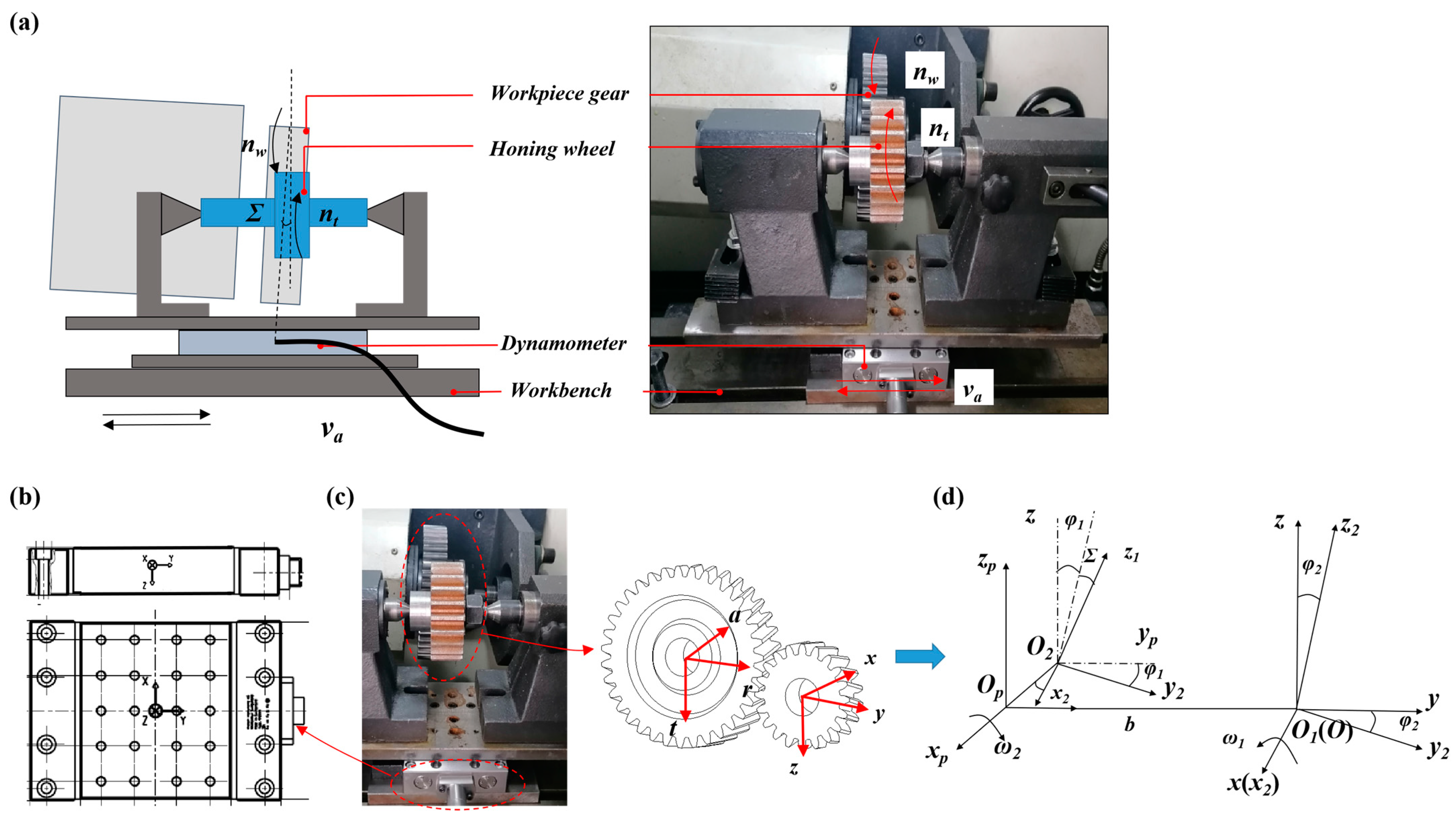
3. Experimental Setup

The experiment described in this section is carried out by using an SMY-4620 external gear honing machine, as shown in Figure 4a; the workpiece gear is mounted on the main drive shaft and its rotation axis can be rotated. The honing wheel is mounted on the driven shaft. A Kistler 9129AA dynamometer is fixed on the bench and the honing wheel is attached above the dynamometer. Figure 4b,c show the coordinate systems of the dynamometer and the workpiece gear, wherein the honing wheel coordinate system is aligned with the dynamometer coordinate system, and hence, the dynamometer measurement represents the force components applied to the honing wheel. In order to find the force components of the workpiece gear, further coordinate transformation is required. The moduli of both the honing wheel and workpiece gear are 4 mm, the pressure angle is 20 ° , the number of teeth of the workpiece gear is 44, and the diameter of the pitch circle is 176 mm; the honing wheel is a carbon steel-based CBN-coated gear with 22 teeth and the diameter of the pitch circle is 88 mm. The honing parameters are shown in Table 1 and the honing process is dry grinding. In order to obtain the honing force parameters as accurately as possible, multiple sets of parameters are selected for testing.

4. Results and Discussion

4.1. Honing Force

In the gear honing process, the forces at the contact points on the honing wheel and workpiece gear are equal in value and opposite in their directions. However, there is a cross-axial angle between the rotating gears, and the forces in different coordinate systems are not identical. That means in order to determine the honing forces on the workpiece gear, the measured forces for the honing wheel need to be transformed. For the sake of this transformation, the coordinate systems of the honing wheel and the workpiece gear at the initial and arbitrary moments are established, as shown in Figure 4d, where S p ( O p x p , y p , z p )   and S 2 ( O 2 x 2 , y 2 , z 2 ) are the coordinate systems of the workpiece gear at the initial and arbitrary moments and S ( O x , y , z ) and S 1 ( O 1 x 1 , y 1 , z 1 ) are the coordinate systems of the honing wheel at the initial and arbitrary moments. The rotation axis of the workpiece gear at any moment coincides with x 2 , and that of the honing wheel coincides with x ( x 1 ) . The angular velocities of the honing wheel and workpiece gear are ω 1 and ω 2 , respectively. The workpiece does not move along the axis, while the honing wheel moves along the axis with the velocity v a . Over a period of time, the rotation angles of the honing wheel and workpiece around their axes are φ 1 and φ 2 , respectively.
Let the transformation matrix of the coordinate system S 1 to S 2 be M 12 ; then, the relationship between the components of the honing force in the two coordinate systems can be expressed as follows:
[ F a F r F t ] = M 12 [ F x F y F z ]
In the above equation, M 12 = M 10 · M 02 , where M 10 is the transformation matrix of the coordinate system S 1 to S 0 , which reads as follows:
M 10 = [ 1 0 0 0 c o s φ 1 s i n φ 1 0 s i n φ 1 c o s φ 1 ]
M 02 is the transformation matrix from coordinate system S 0 to S 2 , which can be expressed as below:
M 02 = [ c o s Σ 0 s i n Σ 0 c o s φ 2 c o s Σ s i n φ 2 s i n Σ c o s Σ s i n φ 2 c o s Σ c o s φ 2 ]
Hence, the transformation matrix M 12 can be expressed as below:
M 12 = M 10 · M 02 = [ 1 0 0 0 c o s φ 1 s i n φ 1 0 s i n φ 1 c o s φ 1 ] [ c o s Σ 0 s i n Σ 0 c o s φ 2 c o s Σ s i n φ 2 s i n Σ c o s Σ s i n φ 2 c o s Σ c o s φ 2 ] = [ c o s Σ 0 s i n Σ s i n φ 1 s i n Σ c o s φ 2 c o s φ 1 + c o s Σ s i n φ 2 s i n φ 1 c o s Σ ( c o s φ 1 s i n φ 2 s i n φ 1 c o s φ 2 ) c o s φ 1 s i n Σ c o s φ 2 s i n φ 1 c o s Σ s i n φ 2 c o s φ 1 c o s Σ ( s i n φ 1 s i n φ 2 + c o s φ 2 c o s φ 1 ) ]
Substituting Equation (43) into Equation (40), the force components can be presented as below:
{ F a = cos Σ F x + sin Σ F z F r = sin φ 1 sin Σ F x + ( cos φ 2 cos φ 1 + cos Σ sin φ 2 sin φ 1 ) F y cos Σ ( cos φ 1 sin φ 2 sin φ 1 cos φ 2 ) F z F t = cos φ 1 sin Σ F x + ( cos φ 2 sin φ 1 cos Σ sin φ 2 cos φ 1 ) F y + cos Σ ( sin φ 1 sin φ 2 + cos φ 2 cos φ 1 ) F z
During our experiment, the duration of each test was set to t = 30 s, and the rotation angles of the honing wheel and workpiece gear were integer multiples of the rotation cycle. Therefore, φ 1 = t · π n w / 30 = π n w , φ 2 = t · π n t / 30 = π n t . Thus, Equation (47) can be further written as follows:
{ F a = c o s Σ F x + s i n Σ F z F r = F y F t = c o s Σ F z                      
By substituting the honing forces under different conditions into Equation (48), the honing force applied to the workpiece gear can be obtained. The absolute average values of the honing force components in coordinate systems S 1 and S 2 for different test cases are shown in Table 2.

4.2. Evaluation of Honing Force Model

The determination of the unknown parameters in Equation (18) is complicated since there are three independent variables and one dependent variable in the expression. In order to derive the unknown parameters in the model more conveniently, Equation (18) can be simply transformed by taking
h e q l Σ = v a v A w a p d e q
where heq is the chip thickness.
Then Equation (18) can be expressed as below:
F t l Σ · b = k 1 · ( h e q l Σ ) a 1 F r l Σ · b = k 2 · ( h e q l Σ ) a 2 F a l Σ · b = k 3 · ( h e q l Σ ) a 3
Thus, taking h e q l Σ as the independent variable and F n l Σ · b , F t l Σ · b , and F a l Σ · b as the dependent variables, the unknown parameters can be determined and the curves shown in Figure 5 can be plotted. The constants k1, k2, and k3 of the three curves are 34.211, 33.327, and 23.164, respectively. The constants a1, a2, and a3 are 0.1098, 0.142, and 0.1608, respectively, and the values of R-squared are 0.9556, 0.8689, and 0.8899. The values of R-squared are very close to 1, indicating that the curve fits well and can effectively predict the value of the honing force in three directions. Therefore, Equation (18) can be finally given as below:
{ F t = 34.211 · l Σ · b · ( v a v A w a p d e q ) 0.1098 F r = 33.327 · l Σ · b · ( v a v A w a p d e q ) 0.142 F a = 23.164 · l Σ · b · ( v a v A w a p d e q ) 0.1608
To verify the reliability of the above results, comparisons between theoretical and experimental results were carried out. The experimental results were selected as the average of all the absolute values of honing force, as shown in Figure 6, and the errors between the calculated and measured values in the x, y, and z directions were 8.6%, 15.05% and 10.35%, respectively. The experimental results match well with the theoretical calculated results, demonstrating that the honing force model in this paper is effective for describing the external honing process.

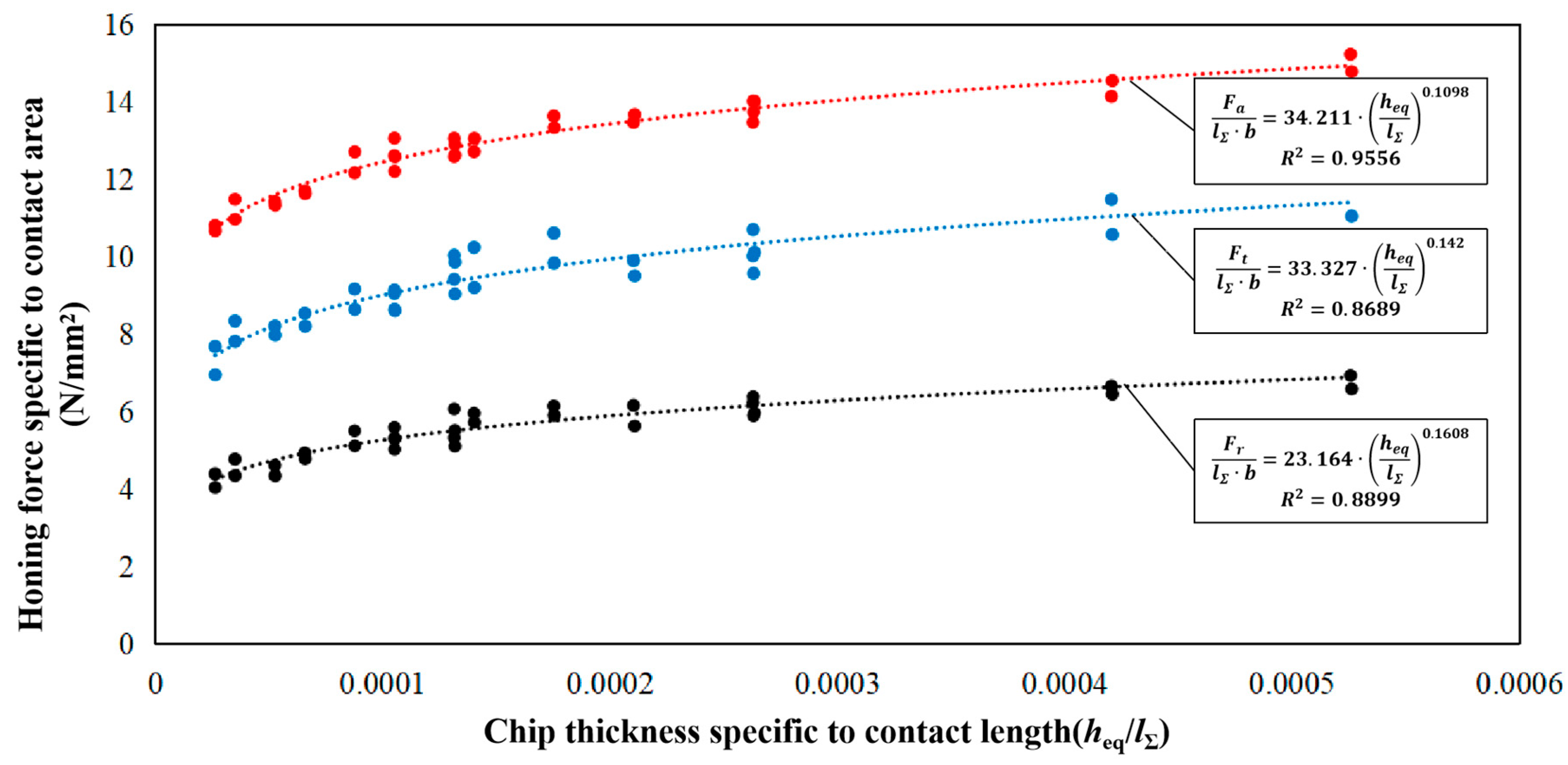
4.3. Specific Honing Energy
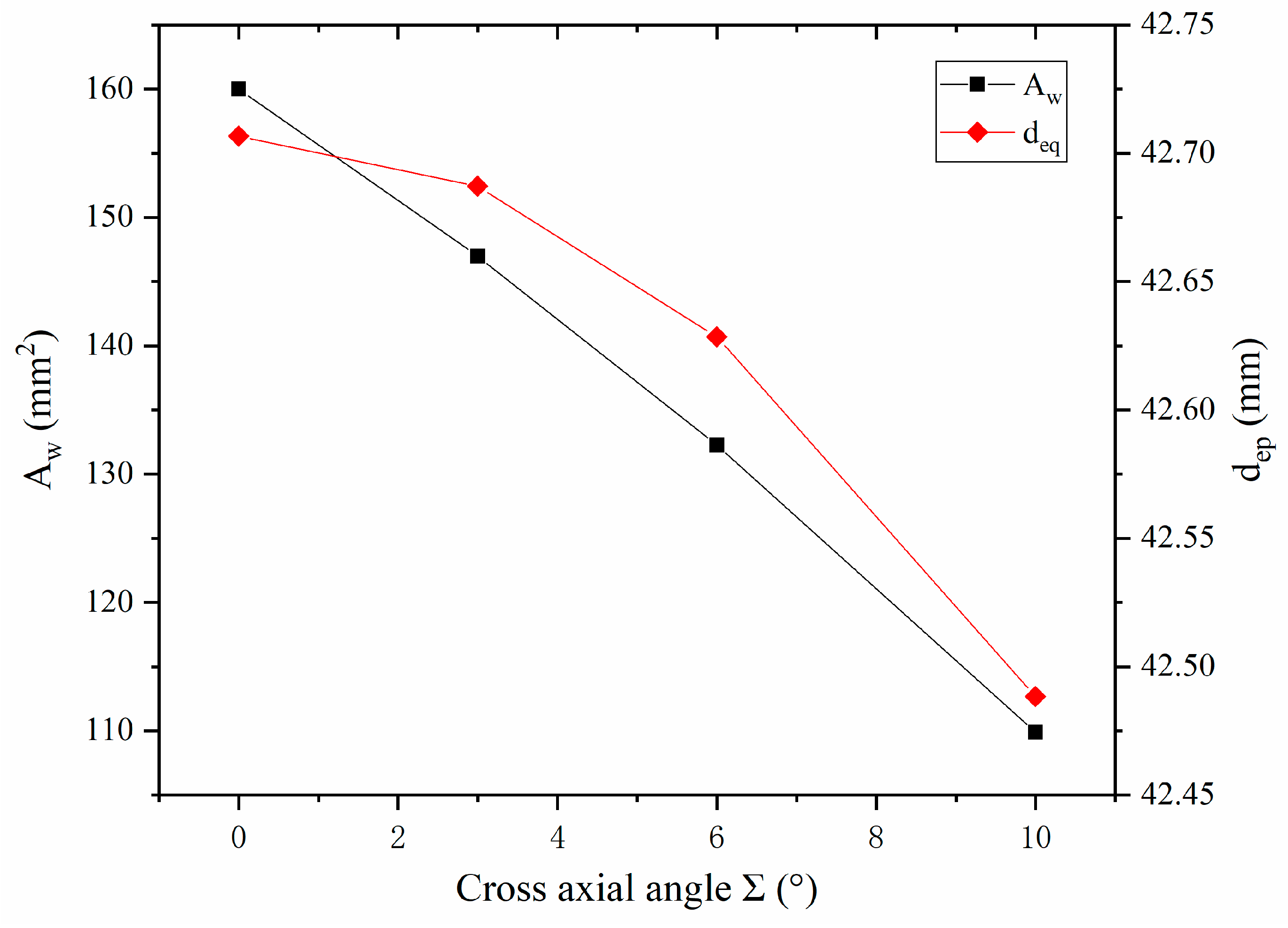
Substituting Equations (15) and (35) and the parameters in Table 1 into Equation (42), the expression for specific honing energy can be obtained as below:
e s = 3649.06 · ( a p ) 0.4196 ( v a ) 0.1608 ( n w ) 0.1608 ( d e q ) 0.4196 A w 4 c o s ( Σ )  
Once the honing force and material removal rate are determined, the magnitude of the specific honing energy can be calculated according to Equation (52). This equation can be used to predict the effects of machining parameters such as depth of cut, axial feed velocity, workpiece gear rotational speed, and cross-axial angle on the specific honing energy.

4.3.1. The Relationship between d e q and A w 4 versus Cross-Axial Angle Σ

Before discussing the effect of processing parameters on specific honing energy, it is necessary to determine two other parameters in Equation (52): d e q and A w 4 . The former is the equivalent honing wheel diameter and the latter is the contact area between the honing wheel and the workpiece gear. d e q and A w 4 are expressed in Equations (17) and (38). With the workpiece and honing wheel sizes fixed, the equivalent diameter and contact area only vary with the cross-axial angle and are independent of other parameters. Substituting the known parameters into Equations (17) and (38), the relationship between d e q , A w 4 , and the cross-axial angle can be obtained, as shown in Figure 7. With the increase in the cross-axial angle, both the contact area and equivalent diameter decrease. When the cross-axial angle changed from 0° to 10°, the contact area underwent a 31% reduction whereas the equivalent diameter only reduced by 0.5%, which is a minor quantity and can be ignored. Hence, in the subsequent discussion on the influence of processing parameters on specific honing energy, the equivalent diameter can be regarded as a fixed coefficient while the influence of contact area on honing energy can be expressed by the effect of the cross-axis angle on specific honing energy.

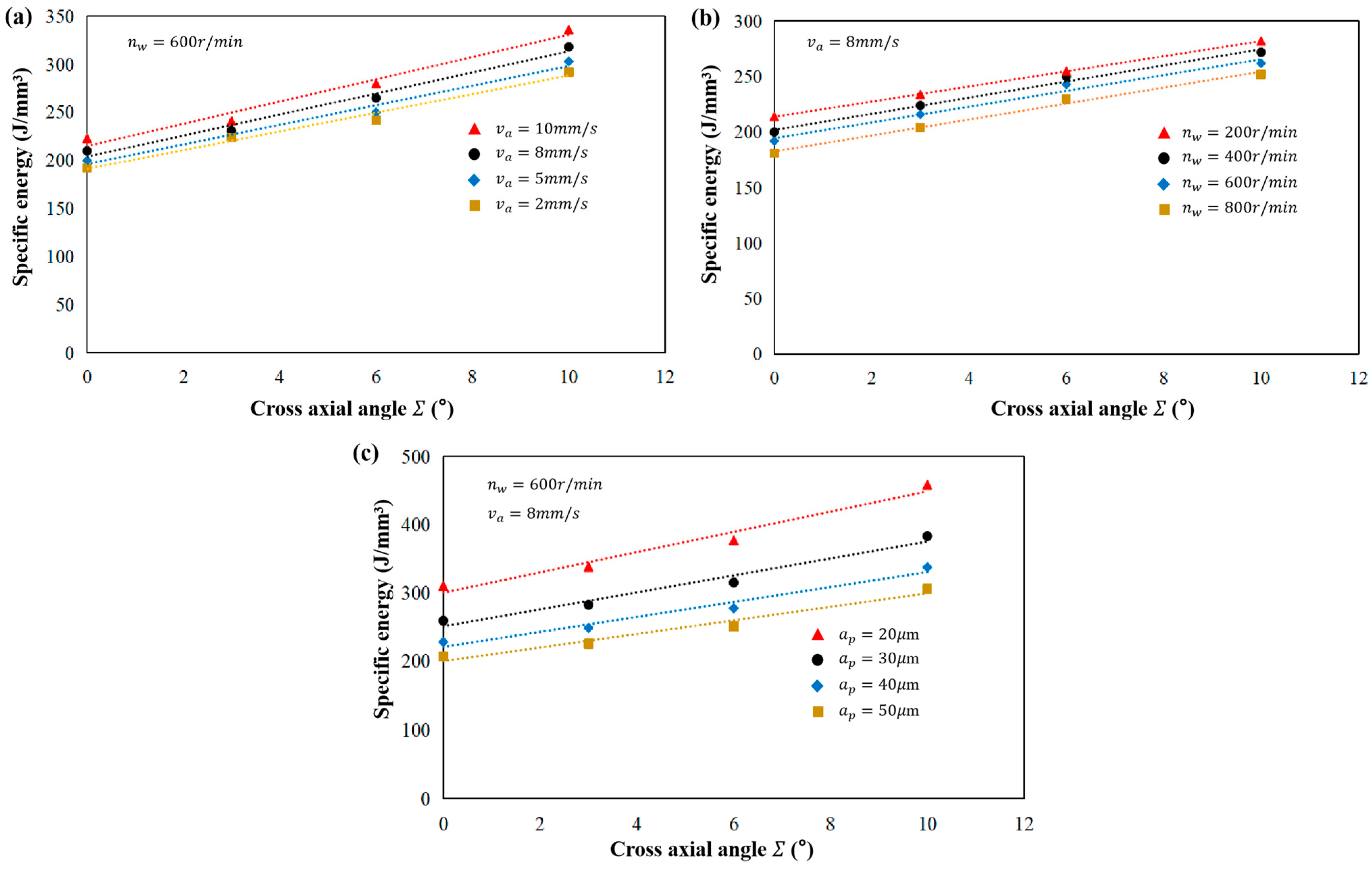
4.3.2. Effect of Processing Parameters on Specific Honing Energy

Figure 8 shows the effect of varying processing parameters on specific honing energy. When the workpiece rotational speed and depth of cut are fixed, the increase in the cross-axial angle and axial feed velocity leads to an increase in specific honing energy (Figure 8a). This is because with the increase in the cross-axial angle, the contact area decreases and the honing force increases, and as a result, the material removal rate decreases, leading to an increase in specific honing energy. With the increase in axial feed velocity, the honing force increases obviously (Table 2), while the material removal rate increases slightly, and hence, the specific honing energy increases. That means that a larger cross-axial angle and axial feed velocity make it difficult to remove material from the workpiece. When the axial feed velocity and depth of cut are fixed, the specific honing energy decreases as the workpiece rotational speed increases (Figure 8b). This is because a higher rotational speed reduces the honing force (Table 2) and increases the material removal rate, resulting in a reduction in specific honing energy. This implies that increasing the rotational speed improves the material removal efficiency.
Given a fixed workpiece rotational speed and axial feed velocity, an increase in the depth of cut causes a decrease in the specific honing energy (Figure 8c). This is because an increase in cutting depth results in an increase in the material removal rate, indicating that a larger cutting depth makes easier to remove material from the workpiece. Similar results for the fluctuation of specific energy with processing parameters in grinding were also experimentally observed in previous studies [7,26,27].
Specific energy can quantitatively measure the material removal efficiency (machinability) in the machining process, and when the specific energy is larger, the material removal efficiency is lower, and when the situation is vice versa, the material removal efficiency is higher. Therefore, in practical machining, specific honing energy can be reduced by controlling the processing parameters so as to improve the machining efficiency [7,16,27], which is valuable for further studying and revealing the mechanisms of material removal, abrasive wear, honing accuracy, and surface quality of honed teeth.
Gear honing is, in essence, a kind of low-speed grinding [9], and the variations in specific honing energy are similar to those in grinding. During the honing of hardened gears, as the hardness of the workpiece surface is high, the material is difficult to be removed and the material removal rate is low. Therefore, the specific grinding energy is high. In order to improve material removal efficiency, aside from properly choosing processing parameters, the imply of super-hard and wear-resistant abrasives is also imperative. To this end, the CBN-coated honing wheels were used in this work to develop the model. However, overall, compared to gear grinding, gear honing process is a gear precision machining method where the machined gear has a higher accuracy level and less machinable margin [28], which objectively results in a lower material removal rate and a higher specific honing energy.

5. Conclusions

The study proposed an analytical model to predict the specific energy in honing of hardened gears, and the following conclusions can be made:
  • In order to develop the specific energy model, a material removal rate and honing force model are developed based on both the formulation of the contact area of the meshing surface as well as the transformation of coordinates. The honing force, material removal rate, and specific honing energy models are in good agreement with the experimental results.
  • In gear honing, the variation of processing parameters greatly effects the specific energy, such that an increase in the cross-axial angle and axial feed velocity causes an increase in specific energy, while an increase in cutting depth and rotational spindle speed leads to a decrease in specific energy. Therefore, properly choosing the processing parameters may effectively improve honing efficiency.
  • This work provides insightful understanding of the material removal mechanism of external gear honing and establishes a model to reasonably predict the specific honing energy, although there are some simplifications that have been made in the modeling process. Future works would involve evaluations of the surface quality of honed gears and the effect of grain wear on specific energy.

Author Contributions

Conceptualization, F.W. and Y.C.; methodology, F.W. and Y.G.; software, F.W., Y.L. and D.Z.; validation, F.W., Y.C. and Y.G.; formal analysis, F.W.; investigation, F.W., and D.Z.; data curation, F.W. and Y.L.; writing—original draft preparation, F.W. and Y.C.; writing—review and editing, F.W., Y.G. and R.W.; visualization, F.W.; supervision, Y.C. and R.W.; project administration, Y.G.; funding acquisition, F.W. and Y.G. All authors have read and agreed to the published version of the manuscript.

Funding

This research work is supported by the Ningxia Natural Science Foundations (Grant No. 2023AAC02047 and No. 2020AAC03203), National Natural Science Foundation of China (Grant No. 51765001), and Youth Talent Development Program of North Minzu University (Grant No. 2023QNPY13).

Institutional Review Board Statement

Not applicable.

Informed Consent Statement

Not applicable.

Data Availability Statement

Not applicable.

Conflicts of Interest

The authors declare no conflict of interest.

Abbreviations

CBNcubic boron nitride
e s   ( J / mm 3 ) specific honing energy
P   ( W ) honing power
Q w   ( mm 3 / s ) material removal rate
F a ,   F r   and   F t   ( N ) honing force components in the coordinate system of the workpiece gear
x ,   y   and   z the coordinate system of the honing wheel
v ( 12 ) relative velocity vector between the workpiece gear and honing wheel
F force vector on the tooth surface of the workpiece gear
O 1 , O 2 rotational centers of workpiece gear and the honing wheel
v t ( 12 ) ,   v r ( 12 ) and   v a ( 12 ) ( mm / s ) components of relative velocity in tangential, radial, and axial directions
M ( 1 ) , M ( 2 ) contact points on the tooth surface of the workpiece gear and honing wheel
v a ( 1 ) , v r ( 1 )   and   v t ( 1 ) ( mm / s ) velocity components   of   M ( 1 )
v x ( 2 ) , v y ( 2 )   and   v z ( 2 ) ( mm / s ) velocity components   of   M ( 2 )
ρ 1 and ρ 2   ( mm ) distance   from   points   M ( 1 ) and M ( 2 ) to their rotational center
r b w and r b t   ( mm ) radius of base circles of the workpiece gear and honing wheel
α   ( o ) pressure angle
r w and r t   ( mm ) radius of pitch circles of the workpiece gear and honing wheel
v N 1     ( mm / s ) linear velocity   of   point   N 1 relative to O 1
v N 2     ( mm / s ) linear velocity   of   point   N 2 relative to O 2
v M 1     ( mm / s ) linear velocity   of   point   M relative to O 1
v M 2     ( mm / s ) linear velocity   of   point   M relative to O 2
v M N 1   ( mm / s ) linear velocity of point M relative to N 1
v M N 2   ( mm / s ) linear velocity   of   point   M relative to N 2
v A w   ( mm / s ) equivalent velocity of workpiece gear
n w   ( r / min ) rotational velocity of workpiece gear
v A t   ( mm / s ) equivalent velocity of honing wheel
n t ( r / min ) rotational velocity of honing wheel
r A w   and   r A t   ( mm / s ) equivalent radii of the workpiece gear and honing wheel
F n   ( N ) normal equivalent honing force
d e q   ( mm ) Diameter of equivalent grinding wheel
l Σ   ( mm ) contact length
k 1 ~ k 3   and   a 1 ~ a 3 empirical constants
b   ( mm ) contact width
Z H (/s)total number of teeth in contact in unit time
q w   ( mm 3 ) material volume removed from the workpiece per cutting pass
Z w   and   Z t     the number of teeth of workpiece gear and honing wheel
ε α the gear contact ratio
α ( o ) the meshing angle
α a t   and   α a w   ( o ) addendum pressure angles of honing wheel and workpiece gear
A w ( A w 1 ~ A w 4 ) ( mm 2 ) contact area of the meshing area
a e q   ( μ m ) equivalent cutting depth of the tooth surface in a single instance of contact
a p   ( μ m ) the cutting depth
x w and x t the workpiece gear and honing wheel rotation axes
O 1 O 2 the gear center distance
w ( mm ) the width of workpiece gear
h   ( mm ) the height of the contact area
d f w , d f t   ( mm ) addendum diameters of the workpiece gear and honing wheel
Δ x   and   Δ y   ( mm ) axial and radial offset of the honing wheel
Σ   ( o ) cross axis angle
m   ( mm ) module
T   ( s ) the period of axial relative movement

References

  1. Bergs, T. Cutting force model for gear honing. CIRP Ann. 2018, 67, 53–56. [Google Scholar]
  2. Klocke, F.; Gorgels, C.; Vasiliou, V. Analysis of the influence of gear dimensions on cutting speed and contact conditions during the gear honing process. Prod. Eng. 2009, 3, 255–259. [Google Scholar]
  3. Yuan, B.; Han, J.; Wang, D.; Zhu, Y.; Xia, L. Modeling and analysis of tooth surface roughness for internal gearing power honing gear. J. Braz. Soc. Mech. Sci. Eng. 2017, 39, 3607–3620. [Google Scholar]
  4. Gao, Y.; Wang, F.; Liang, Y.; Han, J.; Su, J.; Tong, Y.; Liu, L. Cutting Performance of Randomly Distributed Active Abrasive Grains in Gear Honing Process. Micromachines 2021, 12, 1119. [Google Scholar] [PubMed]
  5. Gao, Y.; Ren, X.; Han, J.; Wang, F.; Liang, Y.; Liu, L. Simulation to Microtopography Formation of CBN Active Abrasives on a Honing Wheel Surface. Coatings 2021, 11, 540. [Google Scholar]
  6. Wang, F.; Chen, Y.; Gao, Y.; Liang, Y.; Su, J.; Liu, L. Peridynamic Simulation to Fracture Mechanism of CBN Grain in the Honing Wheel Dressing Process. Micromachines 2021, 12, 1186. [Google Scholar]
  7. Singh, V.; Venkateswara Rao, P.; Ghosh, S. Development of specific grinding energy model. Int. J. Mach. Tools Manuf. 2012, 60, 1–13. [Google Scholar]
  8. Sarwar, M.; Persson, M.; Hellbergh, H.; Haider, J. Measurement of specific cutting energy for evaluating the efficiency of bandsawing different workpiece materials. Int. J. Mach. Tools Manuf. 2009, 49, 958–965. [Google Scholar]
  9. Brinksmeier, E.; Schneider, C. Grinding at very Low Speeds. CIRP Ann. 1997, 46, 223–226. [Google Scholar]
  10. Malkin, S.; Guo, C. Grinding Technology: Theory and Application of Machining with Abrasives; Industrial Press Inc.: New York, NY, USA, 2008. [Google Scholar]
  11. Ghosh, S.; Chattopadhyay, A.B.; Paul, S. Modelling of specific energy requirement during high-efficiency deep grinding. Int. J. Mach. Tools Manuf. 2008, 48, 1242–1253. [Google Scholar]
  12. Ren, Y.H.; Zhang, B.; Zhou, Z.X. Specific energy in grinding of tungsten carbides of various grain sizes. CIRP Ann. 2009, 58, 299–302. [Google Scholar]
  13. Zheng, Z.; Huang, K.; Lin, C.; Zhang, J.; Wang, K.; Sun, P.; Xu, J. An analytical force and energy model for ductile-brittle transition in ultra-precision grinding of brittle materials. Int. J. Mech. Sci. 2022, 220, 107107. [Google Scholar]
  14. Jia, D.; Li, C.; Zhang, Y.; Yang, M.; Wang, Y.; Guo, S.; Cao, H. Specific energy and surface roughness of minimum quantity lubrication grinding Ni-based alloy with mixed vegetable oil-based nanofluids. Precis. Eng. 2017, 50, 248–262. [Google Scholar]
  15. Dai, C.; Yin, Z.; Ding, W.; Zhu, Y. Grinding force and energy modeling of textured monolayer CBN wheels considering undeformed chip thickness nonuniformity. Int. J. Mech. Sci. 2019, 157–158, 221–230. [Google Scholar]
  16. Rowe, W.B. Principles of Modern Grinding Technology, 1st ed.; William Andrew: Norwich, NY, USA, 2014. [Google Scholar]
  17. Napoles Alberro, A.; Gonzalez Rojas, H.A.; Sanchez Egea, A.J.; Hameed, S.; Pena Aguilar, R.M. Model Based on an Effective Material-Removal Rate to Evaluate Specific Energy Consumption in Grinding. Materials 2019, 12, 939. [Google Scholar]
  18. Li, W.; Wang, Y.; Fan, S.; Xu, J. Wear of diamond grinding wheels and material removal rate of silicon nitrides under different machining conditions. Mater. Lett. 2007, 61, 54–58. [Google Scholar]
  19. Satyarthi, M.K.; Pandey, P.M. Modeling of material removal rate in electric discharge grinding process. Int. J. Mach. Tools Manuf. 2013, 74, 65–73. [Google Scholar]
  20. Ghosh, G.; Sidpara, A.; Bandyopadhyay, P.P. Theoretical and experimental investigation of material removal rate in shape adaptive grinding of HVOF sprayed WC-Co coating. Precis. Eng. 2021, 72, 627–639. [Google Scholar]
  21. Ren, L.; Zhang, G.; Wang, Y.; Zhang, Q.; Wang, F.; Huang, Y. A new in-process material removal rate monitoring approach in abrasive belt grinding. Int. J. Adv. Manuf. Technol. 2019, 104, 2715–2726. [Google Scholar]
  22. Li, L.; Ren, X.; Feng, H.; Chen, H.; Chen, X. A novel material removal rate model based on single grain force for robotic belt grinding. J. Manuf. Process. 2021, 68, 1–12. [Google Scholar]
  23. Sun, H.; Chen, Z.; Ge, W. Mechanical Principle; Higher Education Press: Beijing, China, 2013. [Google Scholar]
  24. Ren, J.; Hua, D. Grinding Principle; Publishing House of Electronics Industry: Beijing, China, 2011. [Google Scholar]
  25. Faydor, L.L.; Alfonso, F. Gear Geometry and Applied Theory, 2nd ed.; Cambridge University Press: Cambridge, UK, 2004. [Google Scholar]
  26. Mayer, J.E.; Price, A.H.; Purushothaman, G.K.; Dhayalan, A.K.; Pepi, M.S. Specific Grinding Energy Causing Thermal Damage in Helicopter Gear Steel. J. Manuf. Process. 2002, 4, 142–147. [Google Scholar] [CrossRef]
  27. Sun, Z.; Wang, S.; To, S.; Xu, S.; Guo, G. Modelling and analysis of the specific cutting energy for ultra-precision diamond cutting of Ti6Al4V alloy. J. Manuf. Process. 2023, 85, 844–857. [Google Scholar]
  28. Mehta, D.T.; Rathi, M.G. A Review on Internal Gear Honing. Int. J. Eng. Res. Technol. 2013, 2, 973–983. [Google Scholar]
Disclaimer/Publisher’s Note: The statements, opinions, and data contained in all publications are solely those of the individual author(s) and contributor(s) and not of MDPI and/or the editor(s). MDPI and/or the editor(s) disclaim responsibility for any injury to people or property resulting from any ideas, methods, instructions or products referred to in the content.
Figure 1. Velocity analysis of external honing process: (a) external honing model; (b) velocity components on workpiece gear tooth surface; (c) relative velocity analysis of honing process.
Energies 16 05744 g001
Figure 2. Equivalent model for external gear honing process.
Energies 16 05744 g002
Figure 3. Modeling of contact area between honing wheel and workpiece gear: (a) contact area with radial misalignment; (b) contact area with axial misalignment; (c) contact area with angular, radial, and axial misalignments (quadrilateral area); (d) contact area with angular and radial misalignments (triangular area).
Energies 16 05744 g003
Figure 4. Experiment scheme: (a) experimental setup; (b) coordinate system of dynamometer; (c) coordinate systems of honing wheel and workpiece gear; (d) coordinate transformation scheme.
Energies 16 05744 g004
Figure 5. Modeling of honing force.
Energies 16 05744 g005
Figure 6. Comparison of measured and calculated honing force components.
Energies 16 05744 g006
Figure 7. Relationship between d e q and A w 4 versus cross-axial angle.
Energies 16 05744 g007
Figure 8. Effect of honing parameters on specific energy: (a) v a ; (b) n w ; (c) a p .
Energies 16 05744 g008
Table 1. Experimental conditions.
Honing ParametersValue
Workpiece 20 CrMnTi ,   module = 4   mm ,   α   = 20 ° ,   d w = 176 mm ,   b =   20   mm ,   Z w = 44
Honing wheel Carbon   steel   with   CBN   abrasive   grains ,   module = 4   mm ,   α = 20 ° , d t = 88 mm ,   b = 30   mm ,   Z t = 22
Feed   velocity   v a ( mm / s ) 2, 5, 8, 10
Cross - axial   angle   Σ ( o ) 0, 3, 6, 10
Honing   wheel   rotational   speed   n t ( r / min )400, 800, 1200, 1600
Workpiece   gear   rotational   speed   n w   ( r / min )200, 400, 600, 800
Cutting   depth   a p ( μ m )20
Table 2. Experimental values of external honing force.
No. Σ ( o ) v a ( m m / s ) n t   ( r / m i n ) n w   ( r / m i n ) Fx (N)Fy (N)Fz (N)Fa (N)Fr (N)Ft (N)
102400200136 60 107 136 60 107
2021200600130 57 98 130 57 98
305400200156 76 126 156 76 126
4051200600151 65 122 151 65 122
508400200161 66 119 161 66 119
6081200600194 91 154 194 91 154
701040020017982 145179 82 145
80101200600218 101 179 218 101 179
932800400202 92 166 202 92 166
10321600800177 83 129 181 83 129
1135800400166 71 121 170 71 121
12351600800210 90 154 214 90 154
1338800400196 85 147 200 85 147
14381600800238 106 176 243 106 176
15310800400222 101 167 227 101 167
163101600800255 115 198 260 115 198
1762400200251 102 191 256 102 191
18621200600233 100 173 242 100 172
1965400200216 90 159 225 90 158
20651200600265 125 197 277 125 196
2168400200257 117 180 268 117 179
22681200600309 135 231 321 135 230
23610400200293 126 201 304 126 200
246101200600333 148 243 347 148 242
25102800400302 137 221 315 137 220
261021600800266116 177282 116 174
27105800400251 104 165 266 104 162
281051600800303 132 187 321 132 184
29108800400296130 176314 130 173
301081600800341 151 234 362 151 230
311010800400322 140 219 341 140 216
3210101600800363159 249385 159 246
Disclaimer/Publisher’s Note: The statements, opinions and data contained in all publications are solely those of the individual author(s) and contributor(s) and not of MDPI and/or the editor(s). MDPI and/or the editor(s) disclaim responsibility for any injury to people or property resulting from any ideas, methods, instructions or products referred to in the content.

