Article

On the Efficiency of Mobile Hydraulic Power Packs Operating with New and Aged Eco-Friendly Fluids

1
Dipartimento di Ingegneria Industriale, Elettronica, e Meccanica (DIIEM), Roma TRE University, Via Vito Volterra 62, 00146 Rome, Italy
2
Institute of Sciences and Technologies for Sustainable Energy and Mobility, National Research Council (STEMS-CNR), Via Canal Bianco 28, 44124 Ferrara, Italy
*
Author to whom correspondence should be addressed.
Energies 2023, 16(15), 5681; https://doi.org/10.3390/en16155681
Submission received: 13 June 2023 / Revised: 25 July 2023 / Accepted: 27 July 2023 / Published: 28 July 2023
(This article belongs to the Special Issue Application and Analysis in Fluid Power Systems II)

Abstract

:
With the increasing environmental awareness, in many applications, ranging from agriculture to industry and logistics, a wider and wider use of eco-friendly fluids is desirable. Although the chemical and biological aspects related to environmental compatibility have been extensively investigated by industries and researchers for obvious environmental reasons, not much literature is available on the performance of hydraulic components and systems operating with eco-friendly fluids, especially on the possible degradation of performance due to fluid aging. This work is aimed at studying the influence of eco-friendly fluids on the performance of external gear pumps for compact mobile hydraulic power units, which are among the most widespread hydraulic devices in the world, for their cost-effective and flexible construction. Once the experimental set-up is implemented to be well representative of the hydraulic power packs’ typical arrangement, pump performance is investigated. Pump energy performance is obtained in terms of volumetric efficiency and torque efficiency. Alongside the traditional fluid, two types of eco-friendly fluid available in the market are tested. Once the comparison is complete, the investigations are devoted to highlighting the impact of fluid aging on the pump performance. The fluids were aged through 2000 h operation under heavy-duty thermo-mechanical stress on a separate set-up and, afterwards, the pump performance was tested again with aged fluids. The results allow the assessment of the influence of different fluids on pump performance and a comparison of the impact of new versus aged eco-friendly fluids. The eco-friendly fluids exert a significant effect on the pump energy profile. The pump overall efficiency increases, marking an up to 5% improvement, depending on the cases. Fluid aging is found to reduce the pump’s overall performance. This paper addresses the key points defining the pump performance and provides new information on the topic. The results are original and represent a fundamental contribution to define the best practices for energy and maintenance management of hydraulic systems and to foster the deployment of further studies on models and simulation tools to catch the effect of the fluid condition.

1. Introduction

The need to reduce the environmental impact of anthropic activities has become, in the last few years, one of the major drivers in R&D activities in most of the fields of engineering. In the area of fluid power, the energy management of hydraulic systems is a crucial topic, both in mobile and in industrial sectors [1]. This paper is focused on the application of compact hydraulic power packs. Despite each single unit being typically sized in the range of just a few kW of power [2], hundreds of thousands of units are produced per year. Thus, taking the overall installed power into account, even moderate improvements in their efficiency provides a significant energy impact.
Recent advances and improvements in compact power packs are fostering the radical review and innovation of the engineering practices and technologies [3]. A first aspect of innovation is the progressive migration from fossil-based hydraulic oils to eco-friendly biodegradable formulates. A further element is the ever-broader use of pump-controlled systems. The external gear hydraulic pump is traditionally driven at fixed speeds; today, cost-effective electric drives allow the controlled-speed pump management to achieve flow control, pressure control, and load sensing control with fixed displacement units, such as external gear pumps. A third element is related to the opportunity of integrating sensors in hydraulic manifolds and benefiting new programmable logic controllers’ (PLCs) computational power. Hence, sophisticated control logics, once reserved for high-end hydraulic applications, are now available for small hydraulic power packs.
In light of this perspective, the enhancement of pump efficiency is required to efficiently transform mechanical power into hydraulic power. For the electric drive-pump matching and, more generally, in the design of pump-controlled systems, it is also fundamental to assess the pump energy performance in its whole operating range, in terms of overall, volumetric, and torque efficiency. Hence, the development of compact power packs can be oriented to achieving the best compromise between investment and operational costs.
The literature reports that the efficiency of hydraulic pumps depends on complex interactions among several factors. Reference [4] is an interesting review of the ISO standard 4409:2007 [5], which defines the methods of testing and presenting the basic steady-state performance of positive displacement pumps. The overall efficiency is typically analyzed and modelled through the product of volumetric and torque losses [6], although alternative approaches, such as reference [7], have recently been proposed. Regardless of the specific assumptions in the loss modeling, a fundamental point is to rely on robust yet simple models to understand the experimental results and to make virtual predictive models available. The Lumped Parameter (LP) approach has proven to be very effective in modeling the pump efficiency, since the first studies in the field [8]. Many specific research activities are devoted to increasing pump efficiency [9,10], and other efforts are aimed at improving pump technology [11], exploring alternative designs [12], and refining modeling tools [13,14]. Beside the pump technology level, the hydraulic fluid is the other fundamental factor affecting the hydraulic system efficiency [15]. Viscosity, bulk modulus, and density (that depend on pressure and temperature) influence the effective pump performance [4]. Regarding the new eco-friendly fluids, there is still quite limited literature, with very few contributions supported by laboratory tests or simulations rather than experiments in the field [16]. The assessment of a new eco-friendly fluid through an accelerated durability test under laboratory conditions is reported in reference [17], relating to the operational properties of the fluid and to the wear of the pump during the tests. Flow efficiency and physic-chemical properties, such as viscosity, additive depletion, and contamination, were monitored. Furthermore, reference [17] assesses the system performance considering the volumetric efficiency, neglecting, however, the toque efficiency. In reference [18], a detailed CFD modeling of an external gear pump highlights that the use of aged eco-friendly fluids does not degrade the pump volumetric efficiency, encouraging further research on the topic; also, here the torque efficiency is not considered. High pressure piston pumps operating with blends of alternative renewable fluids are investigated in reference [19]. Reference [20] reports a contribution to experimentally evaluating the influence of a biodegradable fluid, globally, on the dig cycle efficiency of a crawler excavator. The process of the aging of the fluid [21], and the development of fluid degradation sensors [22,23], are further emerging topics in the literature.
The current article is devoted to experimentally investigating the efficiency of the gear pumps typically used in small hydraulic power packs. Unlike the literature presented, the authors aim to investigate the change in performance not only from the volumetric loss perspective but by taking overall efficiency and torque efficiency into account, which will be proven to be an essential contribution to the performance degradation of aged fluids.
The research considers two different pumps, belonging to the most used units covering the major power packs configurations, and two different eco-friendly hydraulic fluids available on the market. Their impact on pump performance is investigated and related to what is obtained with a standard mineral oil. Since eco-friendly fluids are biodegradable, their resistance to aging plays a fundamental role. The main question concerns the durability of the fluid performance. In many applications, and particularly in the field of small hydraulic packs, the use of thermal conditioning systems is not common, and the fluid can easily reach relatively high temperatures. Based on these concerns, the performance of the pumps is also tested with the same two eco-friendly fluids after a mechanical–thermal aging process, highlighting the influence of eco-fluids’ aging on pump performance. The results section reports all the trends of efficiencies related to the pump operating conditions and to the new and aged eco-friendly fluids, unveiling how the aged fluids influence the pump performance. Based on a lumped parameter approach, the results are then summarized in a practical form by means of loss coefficients and loss terms.

2. Materials and Methods

2.1. Pump Efficiency

The hydromechanical (or torque) and volumetric efficiency were standardized by ISO 4409:2019 [5]. According to the standard, the actual displacement of the pump was obtained by measuring pump speed and pump flow rate under unloaded condition, to virtually eliminate the volumetric losses due to compressibility and leakage. The pump displacement was calculated according to Equation (1), where Q 0 is the measured flow rate and n 0 is the shaft speed.
V d i s p = Q 0 n 0
According to references [6,8], the overall efficiency of the pump, η p u m p , is expressed as (2):
η p u m p = P h y d P m e c h = Q Δ p n C = Q V d i s p n   · V d i s p Δ p C = η v   η t
where P h y d is the hydraulic power and P m e c h is the mechanical power at pump shaft. The equation can be rewritten as product of Q , flow delivered by the pump, and Δ p pressure difference between delivery and inlet over the product of C , the torque at pump shaft; n is the pump speed. Finally, introducing the pump displacement V d i s p , Equation (2) is expressed as the product of two factors, volumetric and torque efficiency, under the hypothesis of negligible pressure on suction line.

2.2. Hydromechanical Efficiency

The torque efficiency or hydromechanical efficiency of the pump was calculated using Equation (3):
η t = C t h C = V d i s p · Δ p C
where C t h is the theoretical torque at pump shaft. The theoretical torque is written as product of pump displacement V d i s p and Δ p , the pressure difference between delivery and inlet. Once Δ p was set in delivery ambient, torque C was measured at pump shaft. The actual pump displacement was obtained using Equation (1) and the torque efficiency η t was calculated.

2.3. Volumetric Efficiency

The volumetric efficiency is expressed as Equation (4), where Q is the experimentally measured flow rate and Q t h is the theoretical flow rate.
η v = Q Q t h = Q V d i s p · n  
The theoretical flow rate is evaluated as pump displacement times pump speed. The actual flow rate Q differs from the theoretical one Q t h due to volumetric losses. The volumetric losses are due to the pump leakages, to the fluid compressibility, and to the filling efficiency.

2.4. Pump Loss Modeling

To explain and systematize the results it is important to recall some basic yet fundamental definitions and mathematical extrapolations, which were firstly formulated by Wilson [8]. Even if quite basic, these formulations can be a useful operative tool for finding and analyzing the relevant trends within results. According to Wilson’s approach, volumetric efficiency is affected by leakages and by fluid compressibility. The theoretical volumetric flow rate is reduced by the fluid compressibility. Referring to the fluid bulk modulus β , Q β = Q t h Δ p β gives the compressibility term (or compressibility flow rate), whose extent depends on pump load level ( Δ p ) .
η v = 1 Q β Q t h Q L Q t h = 1 Δ p β Ψ s Δ p μ ω
Leakages are due to unideal sealing between delivery and admission sides of the pump, and they are modeled according to the laminar flow in a rectangular meatus. Thus, Q L , the leakage term, is proportional to the group Δ p μ L 3 of laminar flows. Since L 3 can be conveniently referred to the pump displacement V d i s p , Equation (5) is rewritten with the help of the parameter Ψ s , which is the empirical coefficient representing the pump leakage behavior.
According to Wilson’s approach, torque efficiency is affected by friction, which comprises two physical terms (contact and viscous friction). Equation (3) is thus rewritten as Equation (6), where C μ is the torque loss due to viscous friction and C C l is the torque loss due to contact friction. Wilson also introduced the empirical loss term C k that is not explicitly affected by speed and load of the pump.
η t = C t h C t h + C μ + C C l + C k = C t h C t h + Ψ μ μ ω V d i s p + Ψ C l V d i s p Δ p + C k
The actual torque C is thus expressed as the sum of theoretical torque and all the loss terms, as a function of pump speed ω , pump load Δ p , fluid viscosity μ , and pump capacity V d i s p , through the empirical coefficients Ψ μ and Ψ C l [8]. Dividing each term by p m a x · V d i s p , the actual torque C is then expressed in the dimensionless form C * , as in Equation (7):
C * = C t h p m a x · V d i s p + ψ μ · μ · ω · V d i s p p m a x · V d i s p + ψ C l V d i s p Δ p p m a x · V d i s p + C k p m a x · V d i s p
that is rewritten as Equation (8):
C * = p * + ψ μ * · ω * + ψ C l · p * + C k *
where:
  C * = C p m a x · V d i s p ;   p * = p p m a x ; ψ μ * = ψ μ · μ · ω m a x p m a x ;
C k * = C k p m a x · V d i s p ;   ω * = ω ω m a x ;

2.5. Experimental Set-Up

As described above, the measurement of torque and volumetric efficiency was based on the measurement of the pump flow rate, delivery pressure, torque, and pump shaft speed.
A specific experimental set-up was built to replicate the typical operating conditions of the pump in the hydraulic power packs, where the hydraulic manifold body is the key structural element to support pump, electric motor, and tank; valves and other components were integrated in the manifold to realize the most part of the hydraulic circuit.
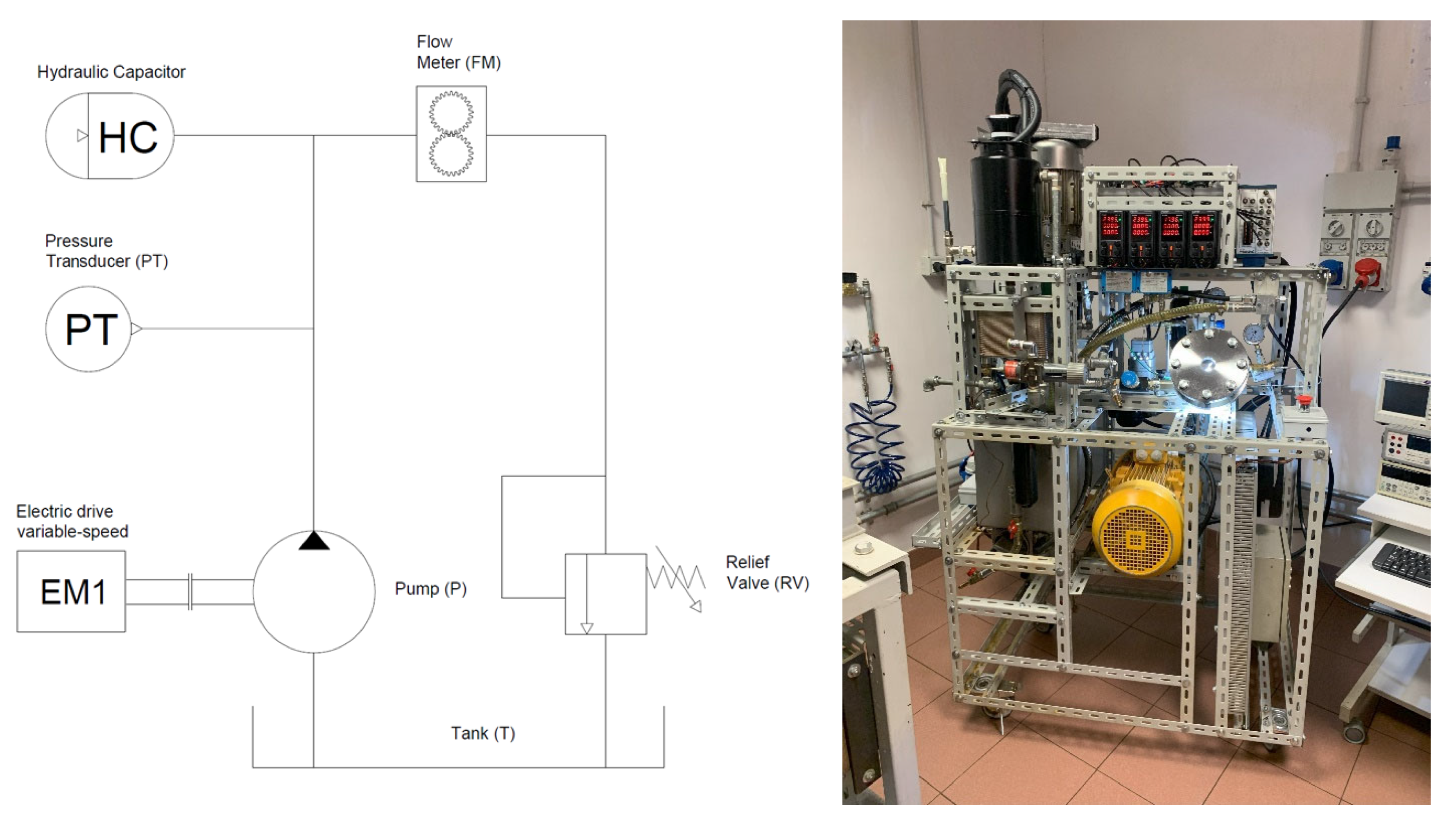
The scheme of the experimental set-up is shown in Figure 1; the pump under test (P) was driven by a variable frequency electric drive (EM1). The pressure measurement in the delivery line was carried out via a pressure transducer (PT). A hydraulic capacitor (HC) limited the pressure fluctuations induced by the gear pump at a negligible level. Flow rate was measured through a volumetric flow meter (FM) on the high-pressure side. The pressure level at the pump head was set through a spring-loaded relief valve (RV).
Figure 2 shows the set-up to measure torque and speed at pump shaft. Usually, the electric motor is coupled to the pump passing the shaft through the hydraulic manifold; here, two hydraulic manifolds were used to build a frame that housed a torque meter (TM), still preserving the standard mount for the electric motor (EM1) and the pump (P).
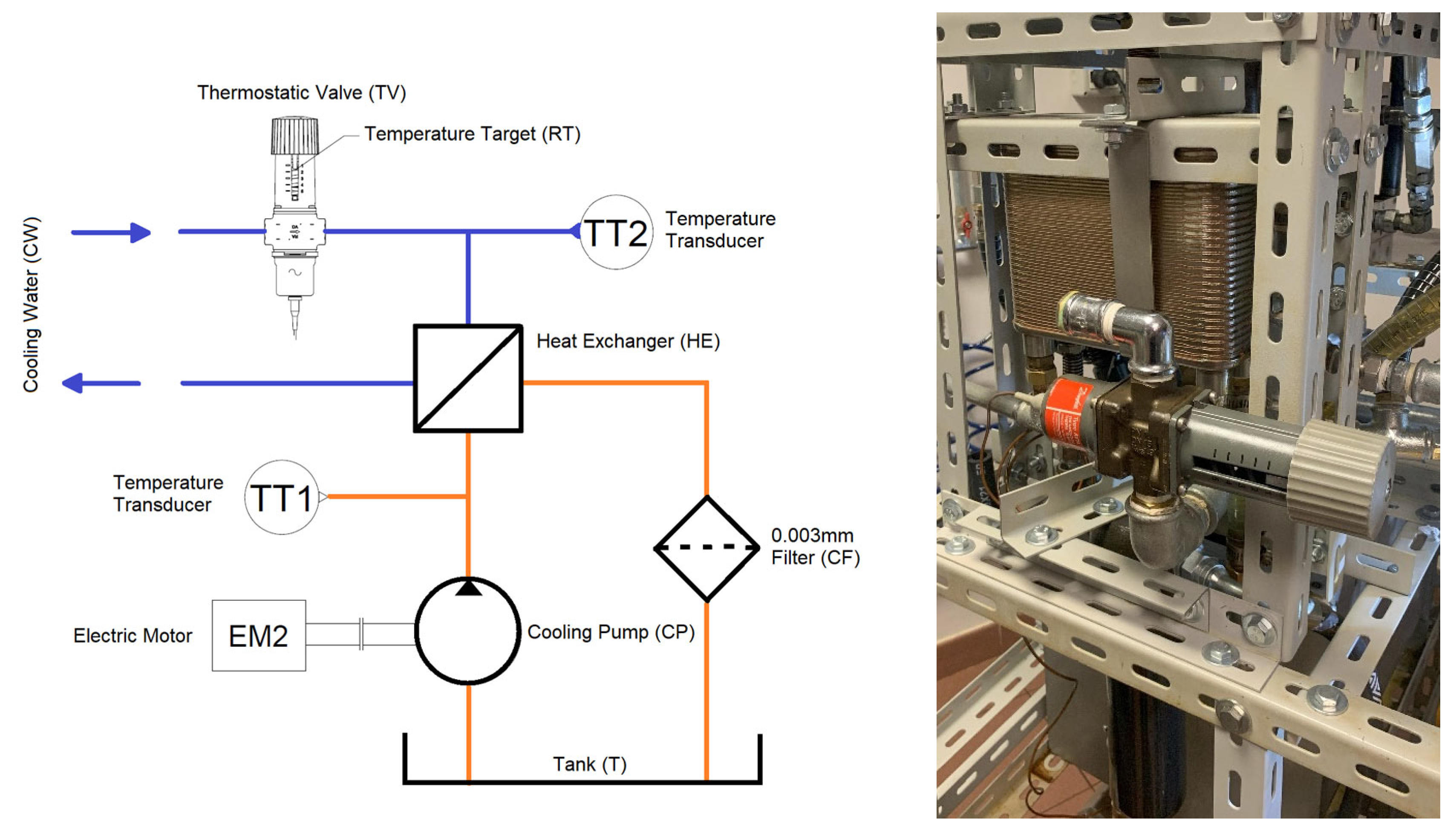
The offline fluid conditioning circuit is shown in Figure 3 and was used to guarantee proper fluid cleanliness and temperature during the tests. The cooling pump (CP) fed the heat exchanger (HE) and the filter (CF). Inlet and return ducts were set to ensure the correct circulation within the tank (T). The thermostatic valve (TV) operated on the cooling water line according to the target temperature, under a closed control loop. The tank temperature was measured (TT1) and continuously monitored during the tests. Table 1 reports the main features of the adopted instrumentation.

2.6. Pumps under Test

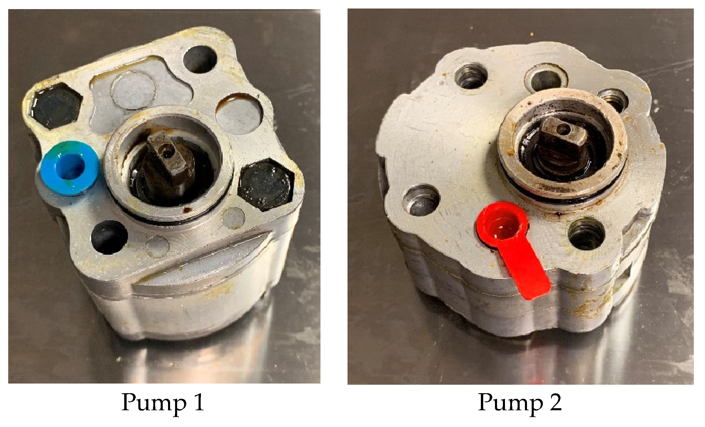
The investigation was carried out on two external gear pumps, belonging to the same dimensional class (01-Group). The pumps had similar displacement, and they were representative of the two mostly used layouts (or families) in the field of hydraulic power packs. The body of Pump 1 (0.8 cc/rev) was made of three parts. The body of Pump 2 (1.2 cc/rev) was simply made of two parts, so that the housing of the gears was blind machined on the main body (Figure 4). An important difference is that Pump 1 included two moving bushes while Pump 2 had just one bushing, then the gears were coupled on one side with the bushing and on the other side directly with the pump body.

2.7. Experimental Test Bench for Aging the Fluids

A specific experimental test bench was developed to perform the study described in [23], with the aim of aging the hydraulic fluids fast and continuously, under controlled conditions and excluding contamination by external agents. The aging was caused by stressing and heating the fluid, simply running the pump with the regulating relief valve. The pressure was set at 70 bar and the fluid temperature was kept at about 90 °C through an electronic control operating on an oil cooler; these settings reproduced the heavy-duty fluid working conditions of the real fluid power system of mobile machines. The typical recommendations on hydraulic fluid replacement refer to a fluid lifetime in the range of 1500–2500 h.
In Figure 5a,b, the schematic layout, in accordance with the Standard ISO 1219, and the picture of the developed test bench are shown, respectively. The main components are an external gear pump (P) driven by an electric motor (EM), a throttle valve (TR), an oil cooler with an electric fan drive (C), a 30 L reservoir (T), a fluid level sensor (LS), a pressure and a temperature sensor (PT and ST), and an electronic control unit. The volume of each eco-friendly fluid treated with the test bench is about 18 L.

2.8. Tested Fluids

To carry out the present study, i.e., to investigate the efficiency of the pumps, some fluids were produced by different companies. As a first step in such a research field, the investigations were limited to three fluids available on the market, in the widely used ISO VG 46 class.
The first one was a standard mineral fluid typically used in hydraulic systems, referred to here as Reference Fluid (named “RF”). The other two were eco-friendly fluids, based on synthetic esters; they met EU Ecolabel performance (HEES, ISO 15380) and are named BSO and BSO-E throughout the text. These fluids are biodegradable substitutes of the mineral RF, belonging to the same viscosity class. They can be generally used as an eco-friendly alternative in the same wide range of applications.
In the case of eco-friendly fluids, they were used to test the pump efficiency as received (New) and after (Aged) a 2000 h degradation process. In order to give a frame of reference on the fluid lifetime, several typical recommendations on hydraulic fluid replacement refer to a fluid lifetime in the range of 1500–2500 h. The main properties of the considered fluids were measured (cinematic viscosity ν, density ρ, resistance to oxidation, and total acid number—T.A.N.) or calculated (dynamic viscosity μ) and are summarized in Table 2.
It must be noted that viscosity changed for both eco-friendly fluids after the aging process, but only for the BSO one does it exceed the ISO VG 46 range. In the case of T.A.N., the eco-friendly fluids showed an increase of almost an order of magnitude after aging. This property is a clear indication of fluid degradation but cannot be uniquely related to other properties by any bijective correspondence mathematic formulation. Finally, the resistance to the oxidation of the fresh eco-friendly fluids, determined by the Rotating Pressure Vessel Oxidation Test (RPVOT) according to ASTM D2272, was nearly twice for BSO-E when compared to BSO, despite the similar properties and compositions reported in their datasheets. This result suggests a faster degradation process in BSO fluid, in agreement with the viscosity measurements.

2.9. Test Cases

For each considered hydraulic fluid, the test points (Ti,j) swept the typical operating range of the pumps. Pump speed ranged from 750 RPM to 3000 RPM, whereas delivery pressure level ranged from 60 to 180 bar, as reported in Table 3.

3. Results

3.1. Pump Displacement

Table 4 reports the measured pump displacements, according to Equation (7), in comparison to the nominal values.

3.2. Performance Profile of the Pumps—Reference Fluid

Figure 6 reports the performance of the two pumps operating with Reference Fluid, in terms of efficiency. The efficiency of each pump is plotted as a function of shaft speed.
The two pumps have similar behavior, but Pump 1 achieves better performance than Pump 2. This could be motivated by the more effective design of Pump 1, provided by the two bushes to compensate the lateral gap, in comparison to the single bushing design of Pump 2. The efficiency trends vs. speed show that the highest efficiency points move towards lower speeds as the pressure decreases. As expected, the working condition generating the greatest decrease in performance is given by high speed at low pressure. This trend is confirmed by Equations (5) and (6), since high speed increases hydro-mechanical speed-related losses and low pressure decreases both the volumetric efficiency for the leakage increase and power hydro-mechanical efficiency for the effective output torque decrease. At minimum pressure (60 bar), the performance trend has a negative slope versus speed; at 90 bar, the efficiency has a global maximum, and the slope becomes negative after 1500 RPM. In the remaining cases at higher pressure, the efficiency trends have positive slopes.

3.3. Biodegradable Fluids

3.3.1. Pump 1

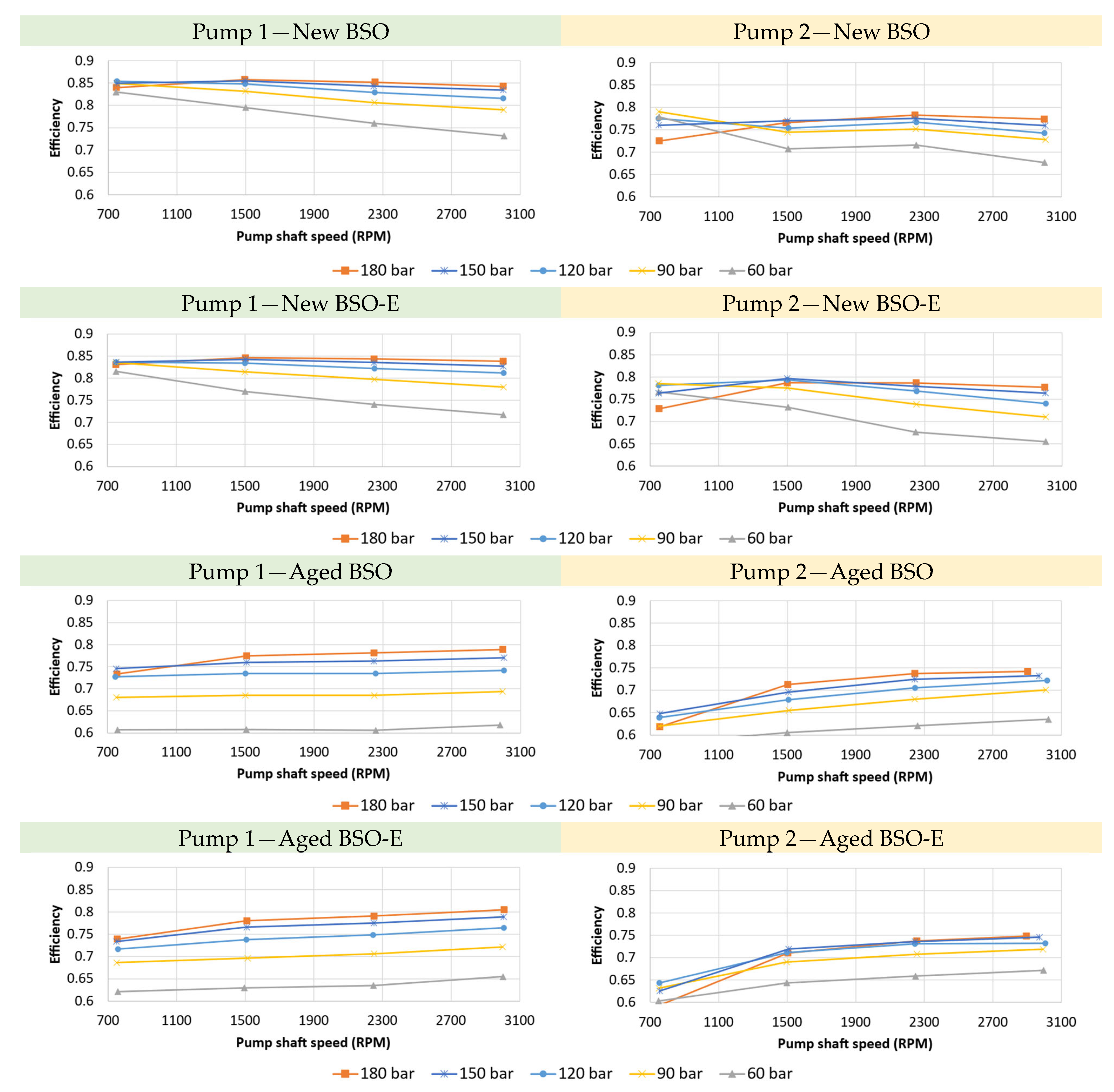
Figure 7 reports the efficiency trends of Pump 1, operating with biodegradable synthetic fluids. It is evident, in comparison to the reference cases, that BSO fresh fluid improves the pump performance. The trends of efficiency vs. speed show a neat improvement (5%) in the low-speed range, whereas a worse performance (3%) with respect to the reference case is recorded in high-speed and minimum load conditions (60 bar), which is, as in the previous case, the lower efficiency point. Switching to BSO-E fluid, similar performance trends are observed, however, the performance degradation at high-speed and low-load conditions is even more pronounced.
Overall, the synthetic fluids have better performance, but the trends are still comparable. On the other hand, large variations can be appreciated looking at the aged fluids’ performances. In fact, aged fluids severely affect the pump performance. Efficiency drops significantly (over 10% at high loads, over 20% in the worse cases at minimum pressure), and its sensitivity to speed and load is modified. A strong dependence on pressure is found, with the efficiency plummeting especially at low pressure.
A remarkable aspect is that, for these fluids, the dependence on speed is weak, as can be seen from the curves, which are almost horizontal, particularly at low load level.

3.3.2. Pump 2

The use of biodegradable fluids does affect the efficiency of Pump 2. At low speeds, both fluids improve the efficiency of Pump 2, although a certain decrease in performance is found in the high-speed range. BSO fluid worsens the efficiency more markedly than BSO-E fluid at high pressures, whereas, at minimum load, BSO-E overcomes BSO in terms of performance. Also, for Pump 2, the switch to aged eco-fluids strongly affects the performance, but the range of efficiency variability is somewhat narrower. The total efficiency drops according to the results of Pump 1, but the speed dependence is still present.

3.4. Volumetric and Torque Efficiency

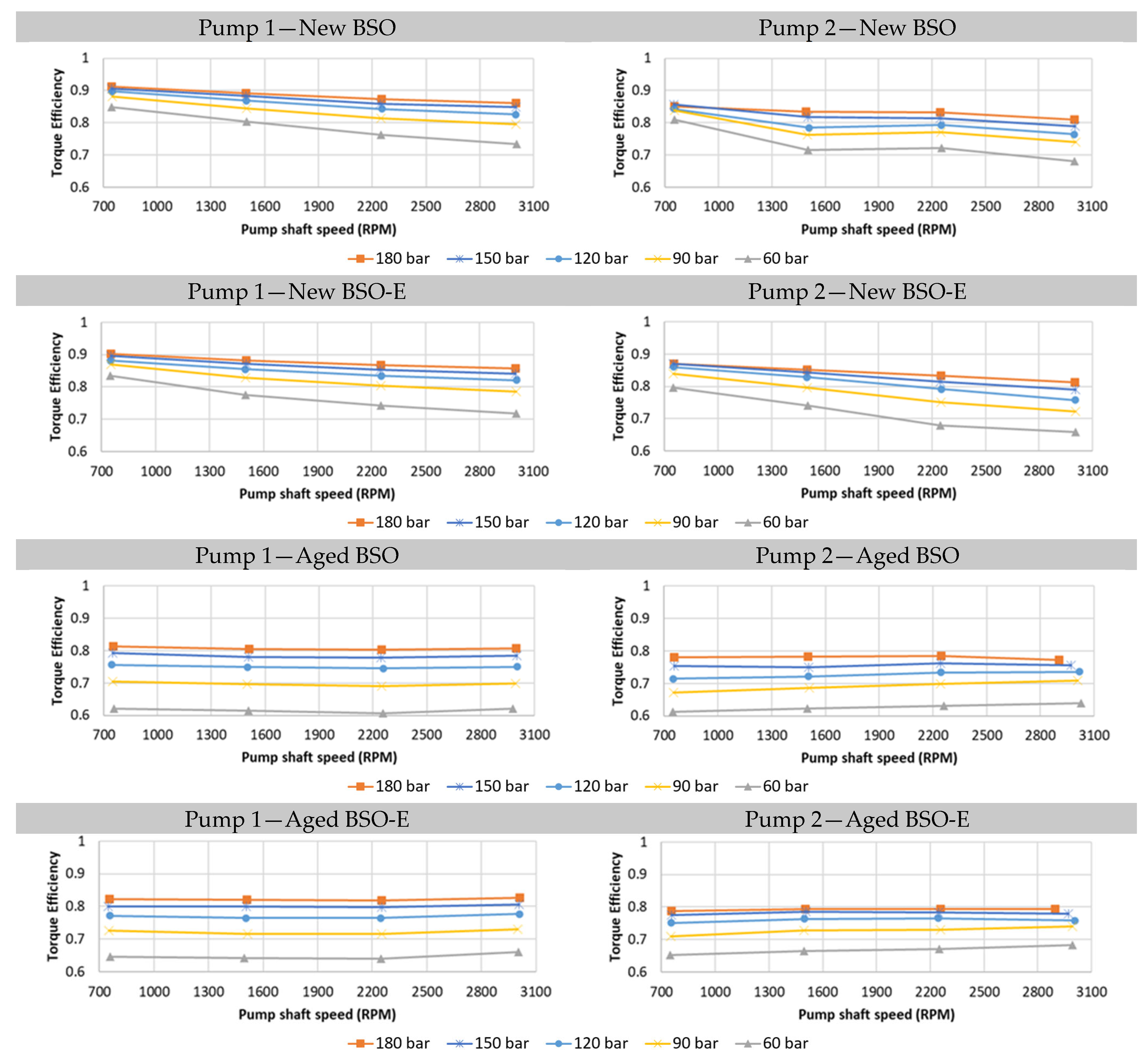
To delve into the performance degradation of the aged fluids, volumetric and torque efficiency trends are investigated. The two tested eco-friendly fluids affect the efficiency of each pump in a similar way. As shown by the trends of Figure 8 and Figure 9, the volumetric performance of both Pump 1 and Pump 2 improves switching to the alternative fluids, despite the aging. Depending on the considered point, improvements are in the order of a few percentage points, bounded within 5%. In fact, looking at the corresponding curve for the same pump, it is possible to note that the volumetric performance is characterized by small variations between the different fluids. The aged fluids do not markedly degrade the performance, confirming the literature trends [18,19]. On the other hand, the huge impact of fluid aging is evident in Figure 10 and Figure 11, which report the torque efficiency trends. New biodegradable fluids have a weak influence on pump performance, but the torque efficiency plummets with the aged fluids. As a final remark, the flat torque efficiency curves highlight an almost negligible dependence on speed. In conclusion, the overall efficiency is mainly affected by the strong increase in hydro-mechanical losses, which is the most remarkable effect highlighted by the experiments.

3.5. Torque Efficiency Loss Coefficients

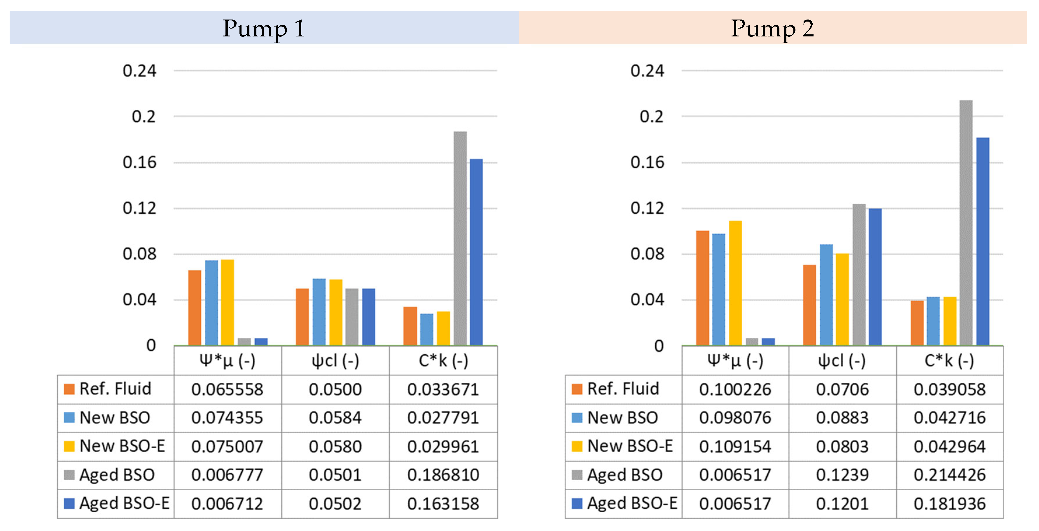
The experimental campaigns have highlighted how the aging of the eco-friendly fluids affects pump efficiency. The aged fluids were found to have an almost negligible toll on volumetric efficiency, slightly improving Pump 1’s and preserving Pump 2’ volumetric performance. Therefore, it is worthy to focus on the torque losses and to fit the experimental data, according to the formulation reported in paragraph 2.13. All the torque efficiencies calculated at the experimental design points have been used to identify the coefficients Ψ μ * , ψ C l , and C k * of Equation (8). On one hand, these terms give the chance to generate a straightforward model of the pump efficiency, which is useful for commenting on these results. On the other hand, their validity can give hints about the performance of pumps belonging to the same “family”. The linear fitting ensures the modeling of the torque efficiency trends within 1–2% accuracy in comparison to the experimental trends, in almost all the considered operating conditions. Only in the case of Pump 2 operating with BSO at low pressure does the model give a 4–5% accuracy, due to the more complex behavior of torque efficiency trends under such conditions. Figure 12 shows the sets of coefficients obtained for Pump 1 and for Pump 2. For new fluids, the prevailing effect is speed-dependent ( ψ μ * , and it is directly related to the viscous losses. The second important contribution is the load-dependent loss ψ C l , which is supposed to establish Coulomb friction behavior. On the other hand, the constant term C k * assumes the lowest values, becoming important only at relatively low speed and low pressure.With both pumps, the aged fluids lead to a substantial increase in the loss term C k * . The speed-related term plummets to a negligible contribution, while the pressure term has diverse variations, depending on the case. For Pump 1, ψ C l tends to slightly decrease with aged fluid, whereas, for Pump 2, an increase in the order of 25–30% is found. As previously introduced, the aging greatly boosts the term C k * , which clearly becomes the most dominant contribution to the losses. This indicates that the torque efficiency decrease is not explicitly dependent on viscous or Coulomb friction.

4. Conclusions

The investigations highlight the influence of eco-friendly fluids on the energy performance of the two most used types of gear pumps for compact hydraulic power packs.
The two eco-friendly hydraulic fluids exert significant effects on the overall efficiency of the pumps. The efficiency increases, marking an up to 5% improvement depending on the cases. These improvements are recorded in both pump types, and they are due to the relevant rise (up to over 10%) of volumetric efficiency in the whole working range of the pumps, that is soundly marked in the most severe conditions (low speed and high pressure). The energy profile of the two pumps improves significantly, but it is worth pointing out that the eco-friendly fluids do not level their performance profile, which still reflects their different characteristics and performance targets.
Biodegradable fluids also affect the torque efficiency, which undergoes a slight decrease. This performance loss is more than compensated by the increase in volumetric efficiency.
After a heavy-duty aging process, based on 2000 h thermal-mechanical stress, the two eco-friendly fluids significantly affect the performance of the pumps. The worsening in overall pump performance is mainly due to the lowering of torque efficiency. The volumetric efficiency slightly decreases, but it never drops below what is obtained with reference mineral fluid. The pump type that achieves the highest performance with new eco-friendly fluids undergoes the largest alteration of torque efficiency and the smallest reduction in volumetric efficiency, highlighting that the link between volumetric and torque efficiencies influences the energy profile of each pump.
The major interest lies in the torque efficiency data, due to their strong dependence on fluid aging. According to the canonical model of torque loss, the torque efficiency points are lumped through torque loss terms and coefficients. In such a form, they provide reference information for the set-up of variable speed motor-pump units and for building advanced control tools that take the energy performance of the pumps into account; indeed, the higher the pump efficiency, the higher the hydraulic power level available in the hydraulic system. Going into more detail, using the Wilson formulation, an original contribution was made, finding that the pressure-dependent losses coefficients had a slight variation, while the constant term had a huge increase, representing the major contribution to efficiency loss; conversely, the speed terms became practically irrelevant.
At least as a first approximation, these results can be generalized and applied to all the pumps belonging to the same dimensional group. Furthermore, additional efforts can be carried out in the future in order to map the progressive decrease at different aging stages and to compare the different types of hydraulic machines and fluids.
Author Contributions

Conceptualization O.C., F.P. and P.M.; methodology, F.P. and P.M.; investigation, F.P., P.M., A.F. and E.F.; writing—original draft preparation, F.P., P.M. and A.F.; supervision, O.C. All authors have read and agreed to the published version of the manuscript.

Funding

This research received no external funding.

Data Availability Statement

The data presented in this study are available on request from the corresponding author.

Conflicts of Interest

The authors declare no conflict of interest.

References

  1. Mahato, A.C.; Ghoshal, S.K. Energy-saving strategies on power hydraulic system: An overview. Proc. Inst. Mech. Engineers Part I J. Syst. Control. Eng. 2021, 235, 147–169. [Google Scholar] [CrossRef]
  2. Suzumori, K.; Faudzi, A.A. Trends in hydraulic actuators and components in legged and tough robots: A review. Adv. Robot. 2018, 32, 458–476. [Google Scholar] [CrossRef]
  3. Schmitz, K. Digital, Reliable, Sustainable—Recent Innovations in Fluid Power. Chem. Eng. Technol. 2023, 46, 4. [Google Scholar] [CrossRef]
  4. Achten, P.; Mommers, R.; Nishiumi, T.; Murrenhoff, H.; Sepehri, N.; Stelson, K.; Palmberg, J.O.; Schmitz, K. Measuring the losses of hydrostatic pumps and motors: A critical review of ISO4409:2007. In Proceedings of the ASME/BATH 2019 Symposium on Fluid Power and Motion Control, FPMC 2019, Sarasota, FL, USA, 7–9 October 2019. [Google Scholar]
  5. ISO 4409:2007(en); Hydraulic Fluid Power—Positive-displacement Pumps, Motors and Integral Transmissions—Methods of Testing and Presenting Basic Steady State Performance. ISO: London, UK, 2007.
  6. Zarotti, G.L.; Nervegna, N. Pump efficiencies approximation and modelling. Engineering 1981, 145–164. [Google Scholar]
  7. Costa, G.K.; Sepehri, N. Understanding overall efficiency of hydrostatic pumps and motors. Int. J. Fluid Power 2018, 19, 106–116. [Google Scholar] [CrossRef]
  8. Wilson, W.E. Performance criteria for positive-displacement pumps and fluid motors. Trans. ASME 1949, 71, 115–120. [Google Scholar] [CrossRef]
  9. Szwemin, P.; Fiebig, W. The influence of radial and axial gaps on volumetric efficiency of external gear pumps. Energies 2021, 14, 4468. [Google Scholar] [CrossRef]
  10. Zardin, B.; Natali, E.; Borghi, M. Evaluation of the hydro—Mechanical efficiency of external gear pumps. Energies 2019, 12, 2468. [Google Scholar] [CrossRef] [Green Version]
  11. Sola, R.; Veronesi, P.; Zardin, B.; Borghi, M. A study on PVD coatings for reduction of friction and wear of swashplate axial piston pumps and motors. Metall. Ital. 2020, 112, 14–23. [Google Scholar]
  12. Devendran, R.S.; Vacca, A. A novel design concept for variable delivery flow external gear pumps and motors. Int. J. Fluid Power 2014, 15, 121–137. [Google Scholar] [CrossRef]
  13. Rituraj, R.; Vacca, A.; Rigosi, M. Modeling and validation of hydro-mechanical losses in pressure compensated external gear machines. Mech. Mach. Theory 2021, 161, 104310. [Google Scholar] [CrossRef]
  14. Rituraj, R.; Vacca, A. Investigation of flow through curved constrictions for leakage flow modelling in hydraulic gear pumps. Mech. Syst. Signal Process. 2021, 153, 107503. [Google Scholar] [CrossRef]
  15. Novaković, B.; Radovanović, L.; Zuber, N.; Radosav, D.; Đorđević, L.; Kavalić, M. Analysis of the influence of hydraulic fluid quality on external gear pump performance. Eksploat. Niezawodn. 2022, 24, 260–268. [Google Scholar] [CrossRef]
  16. Pochi, D.; Fanigliulo, R.; Bisaglia, C.; Cutini, M.; Grilli, R.; Fornaciari, L.; Betto, M.; Pari, L.; Gallucci, F.; Capuzzi, L.; et al. Test rig and method for comparative evaluation of conventional and bio-based hydraulic fluids and lubricants for agricultural transmissions. Sustainability 2020, 12, 8564. [Google Scholar] [CrossRef]
  17. Tulík, J.; Hujo, L.; Kosiba, J.; Jablonický, J.; Jánošová, M. Evaluation of new biodegradable fluid on the basis of accelerated durability test, FTIR and ICP spectroscopy. Res. Agric. Eng. 2017, 63, 1–9. [Google Scholar] [CrossRef] [Green Version]
  18. Muzzioli, G.; Paini, G.; Denti, F.; Paltrinieri, F.; Montorsi, L.; Milani, M. A lumped parameter and CFD combined approach for the lubrication analysis of a helical gear transmission. J. Phys. Conf. Ser. 2022, 2385, 012034. [Google Scholar] [CrossRef]
  19. Chiavola, O.; Frattini, E.; Lancione, S.; Palmieri, F. Operation cycle of diesel CR injection pump via pressure measurement in piston working chamber. Energies 2021, 14, 5385. [Google Scholar] [CrossRef]
  20. Deuster, S.; Schmitz, K. Bio-based hydraulic fluids and the influence of hydraulic oil viscosity on the efficiency of mobile machinery. Sustainability 2021, 13, 7570. [Google Scholar] [CrossRef]
  21. Pochi, D.; Fanigliulo, R.; Grilli, R.; Fornaciari, L.; Bisaglia, C.; Cutini, M.; Brambilla, M.; Sagliano, A.; Capuzzi, L.; Palmieri, F.; et al. Design and Assessment of a Test Rig for Hydrodynamic Tests on Hydraulic Fluids. Lect. Notes Civ. Eng. 2020, 67, 419–429. [Google Scholar] [CrossRef]
  22. Fioravanti, A.; Morandi, S.; Lettieri, S.; Marani, P.; Carotta, M.C. Metal Oxide Gas Sensors from Design to Real Applications: The Case Study of TixSn1-xO2 Solid Solutions. Lect. Notes Electr. Eng. 2023, 918, 92–97. [Google Scholar] [CrossRef]
  23. Fioravanti, A.; Marani, P.; Massarotti, G.P.; Lettieri, S.; Morandi, S.; Carotta, M.C. (Ti,Sn) solid solution-based gas sensors for new monitoring of hydraulic oil degradation. Materials 2021, 14, 605. [Google Scholar] [CrossRef] [PubMed]
Figure 1. (Left)—sketch of the experimental set-up and (Right)—view of the experimental facility.
Energies 16 05681 g001
Figure 2. (Left)—sketch of the set-up for torque efficiency measurement and (Right)—view of pump-torquemeter assembly.
Energies 16 05681 g002
Figure 3. (Left), sketch of the fluid conditioning system; (Right), detail of the thermostatic valve on the cooling water side of the plate heat exchanger.
Energies 16 05681 g003
Figure 4. Pumps under investigation.
Energies 16 05681 g004
Figure 5. Schematic layout (a) and picture (b) of the test bench used to age the eco-friendly fluids.
Energies 16 05681 g005
Figure 6. Efficiency trends, Pump 1 and Pump 2—reference fluid.
Energies 16 05681 g006
Figure 7. Pump 1 and Pump 2—new and aged renewable fluids.
Energies 16 05681 g007
Figure 8. Volumetric efficiency, Pump 1 and Pump 2—reference fluid.
Energies 16 05681 g008
Figure 9. Volumetric efficiency, Pump 1 and Pump 2—new and aged biodegradable fluids.
Energies 16 05681 g009
Figure 10. Torque efficiency, Pump 1 and Pump 2—reference fluid.
Energies 16 05681 g010
Figure 11. Torque efficiency, Pump 1 and Pump 2—new and aged biodegradable fluids.
Energies 16 05681 g011
Figure 12. Loss coefficients according to Equation (8).
Energies 16 05681 g012
Table 1. Hydraulic instrumentation and DAQ System.
ComponentSpecification
EM1Electric drive2-pole asynchronous motor and frequency converter
TMTorque meter and speed sensorBurster 8661
PTPressure transducerKistler 4005 piezo-resistive transducer
FMFlow meter VS 0.2—VSE Volumentechnik GmbH
TT1, TT2Temperature transducerClass 1/10 DIN RTD
Hydraulic manifoldHydronit UB-series manifold
DAQ SystemAI moduleNational Instruments PXIe 5110
IO moduleNational Instruments PXIe 6341 simultaneous multi-channel Analog-Digital Input, 500 kS/s digital input
Table 2. Summary of the main properties of the considered fluids.
FluidStateCinematic
Viscosity ν [cSt]
at 40 °C
Density ρ [kg/m3] at 15 °CT.A.N.
[mg KOH/g]
Resistance to
Oxidation RPVOT [min]
RFNew478800.48300
BSONew479201.01170
BSOAged719327.16
BSO-ENew479330.67300
BSO-EAged469387.14
Table 3. Test cases.
Test CasesDelivery Pressure (bar)
6090120150 180
Pump speed (RPM)750T1,1T1,2T1,3T1,4T1,5
1500T2,1T2,2T2,3T2,4T2,5
2250T3,1T3,2T3,3T3,4T3,5
3000T4,1T4,2T4,3T4,4T4,5
Table 4. Nominal and experimentally determined pump displacements.
Nominal   V d i s p Experimental   V d i s p
Pump 10.8 cc/rev0.855 cc/rev
Pump 21.2 cc/rev1.203 cc/rev
Disclaimer/Publisher’s Note: The statements, opinions and data contained in all publications are solely those of the individual author(s) and contributor(s) and not of MDPI and/or the editor(s). MDPI and/or the editor(s) disclaim responsibility for any injury to people or property resulting from any ideas, methods, instructions or products referred to in the content.