Abstract
To meet the load voltage and power requirements for various specific needs, a typical lithium–ion battery (LIB) pack consists of different parallel and series combinations of individual cells in modules, which can go as high as tens of series and parallel connections in each module, reaching hundreds and even thousands of cells at high voltage (HV) levels. The inhomogeneity among the cells and modules results in voltage imbalances during operation and reduces the overall system efficiency. In this work, a robust and flexible active balancing topology is presented. It can not only mitigate the charge imbalance within a module, i.e., intramodular equalization, but also help to balance the state of charge (SoC) level of the modules in a high voltage pack, i.e., intermodular equalization, which is an often-overlooked topic. The proposed concept was proven by experimental verification on parallel and series configurations of cells in realistically sized modules and practical battery management system (BMS) hardware, when the LIB was both idle and under load.
1. Introduction
Following the green energy transition momentum worldwide, the increasingly high need for and number of installations for renewable energy plants (REPs) have strengthened the role of energy storage systems (ESS) as a crucial component of a decarbonized grid. The energy provided by REPs is intermittent and dependent on natural conditions; hence, in contrast to conventional power plants, a constant supply of energy cannot be available. In a distributed generation (DG) scheme of a power transmission network [1,2] that includes REPs, the intermittent electrical energy must first be converted and stored as other energy types by ESS, such as thermal, mechanical, electromechanical, and electrochemical storage [3,4,5]. After being converted back into electricity, it is delivered to supply the grid demand when needed. Regarding ESS and renewable integration into an exceedingly complex grid, different factors, such as energy storage duration, DG optimization, and resiliency, are becoming exceedingly important [6,7,8,9].
One of the most convenient ESS technologies is a battery storage system, which stores and releases energy directly by means of very efficient electrochemical reactions. The advancements in the electrochemistry field over the last few decades has enabled lithium–ion battery (LIB) technology to become the main viable choice of energy storage medium in portable electronics, hybrid/electric vehicles (H/EVs), and naval and aerospace applications. LIB packs perform well in stationary battery energy storage systems (BESS) by providing energy during power outages, mitigating grid overload by assisting the continuous low-stress operation of the grid, frequency regulation, peak shaving, etc. A typical BESS consists of many cells connected to each other in different combinations. Since the nominal voltage and capacity of an individual cell are not sufficient, they are grouped together and assembled in series and parallel configurations of adequate numbers of cells to meet the rated bus voltage and current specification of a power electronics system. The total number depends on both the cell chemistry and the capacity of each cell. In general, for modularity and safety purposes, the cells are initially assembled into identical modules of several cells, and then the modules are connected to each other, forming a battery pack. Recently, direct cell-to-pack (CTP) and cell-to-chassis (CTC) constructions that reduce the overall pack size and weight have also been studied [10,11,12,13].
Since lithium–ion cells are delicate electrochemical devices, to maintain optimally safe and efficient operation, the voltage, current, and temperature of the LIB pack must be continuously measured by a battery management system (BMS) [14,15]. The main parameters to control or improve the efficiency of battery packs are maintaining a uniform temperature across the entire pack and keeping the cells in an optimum temperature range during operation by proper thermal management in all environmental conditions, controlling the discharge/charge current to avoid extreme heat generation and accelerated aging, and keeping the cells within strict voltage limits to avoid hazardous conditions. As the simplest operation principle, the BMS safety protocol is triggered if any cell voltage or temperature exceeds the safe operation area, and the energy flow to the load, or from the charger, is blocked by opening the contactors to prevent damage to the user and the system. Since the BMS considers the lowest and highest cell voltages, if one or more of the cells deviate from the pack average values in an imbalance condition and reach the under voltage (UV) or over voltage (OV) threshold faster than the rest of the cells during discharge or charge, the operation must immediately, stop even if a certain amount of energy could still be transferred otherwise. Therefore, nonuniformity reduces BESS efficiency, and cell balancing is an indispensable task for all BMS. The imbalance problem has intrinsic and extrinsic causes [16,17,18,19]. Prolonged use of inhomogeneous cells increases the imbalance further. In the worst case, a battery pack may be rendered unusable if it reaches a point at which it cannot be charged or discharged at all as a result of severe inhomogeneity. The key consideration to improve deteriorated system efficiency is employing cell equalization to achieve homogeneity and extending the runtime by preventing one or more of the cells from prematurely reaching the over-discharge or over-charge limits.
Cell balancing methods can be broadly classified as dissipative (passive) and non-dissipative (active) balancing. In passive balancing (PB) scheme, a resistor network wastes the excess energy during charging as heat, making it possible for the uneven cells with lower voltage values to approach the module average. Although PB is the more commonly preferred method in practical applications because of its easy applicability, reliability, and low cost, it is also the more inefficient one. The goal of active balancing (AB), on the other hand, is to redistribute the excess energy and to equalize the state of charge (SoC) among the cells. There is a plethora of AB methods in the literature [20,21,22,23,24,25,26,27,28,29,30,31,32,33,34]. AB can operate in different energy flow directions, such as cell-to-cell, pack-to-cell, and cell-to-pack, and regarding the energy transfer element, it can also be classified as capacitor-based, inductor-based, transformer-based, and converter-based. Even though it might seem to be an obvious choice for high efficiency operations, AB is very rarely employed in practical applications because of its challenges. They can be summarized as complicated control schemes, high costs, and a statistically higher probability of failure due to an increased number of critical circuit components, such as diodes, switches, inductors, and transformers. With all AB types, there are disadvantages, such as high switch currents and low speed for capacitor-based approaches, the possibility of balancing for only adjacent cells by the inductor-based approach, high costs and large volumes/weights for the multiple converter-based approach, and saturation and impedance mismatches for the transformer-based approach [35,36]. In Figure 1, the most common balancing topologies of switched resistor (dissipative), switched capacitor (cell-to-cell direction), adjacent cell-to-cell converter (cell-to-cell direction), multiple converter (pack-to-cell and cell-to-pack direction), and multiple converter with an auxiliary voltage source, which can be another battery or a super-capacitor (SC) bank on an additional shared bus for hybridized operation (cell-to-pack-to-cell direction), are depicted. For simplicity, the power converters are only shown as boxes. In Table 1, a concise summary of AB architectures is presented with required component numbers (switch, capacitor, inductor, diode, converter, and auxiliary accumulator), where N is the number of cells in series [22,23,24].
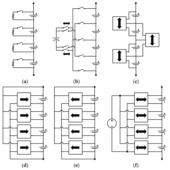
Figure 1.
(a) Switched resistor; (b) switched capacitor; (c) adjacent cell-to-cell; (d,e) multiple converters; (f) multiple converters with auxiliary voltage source/accumulator.

Table 1.
Active balancing topology and component count comparison.
In this article, we introduce an AB topology that, to the best of the authors’ knowledge, has not been previously investigated or implemented in the way that it is presented here. It consists of a high-voltage capable switch array and only a single isolated DC/DC converter that can perform both intramodular and intermodular active balancing. Excess energy can be independently transferred from any module to any cell and vice versa by floating connections. Hence, it can be considered a switched (flying) converter topology. The contributory goals of this paper are;
- (i)
- To present a robust, relatively low-cost, and flexible bidirectional AB topology that eliminates the requirement for multiple power converters, power diodes, transformers, power inductors, and/or auxiliary accumulators that require two additional steps of conversion, thus achieving reduced complexity, a lower failure rate, and lower costs by minimizing the number of components;
- (ii)
- To implement a hardware prototype, including a commercial BMS circuit, DC/DC converter, and switch matrix, to prove that the presented method can be implemented in a real-world application with readily available off-the-shelf components;
- (iii)
- To verify the AB operation by equalizing cells not only within a module but also among the modules as a proof of intermodular balancing concept and achieving pack-level homogeneity for both series-connected and parallel-connected configurations of realistically sized 24-V modules, including a large high voltage (HV) battery pack scenario; and
- (iv)
- To demonstrate the increased runtime and energy delivery of the proposed AB topology when the LIB is under load.
The authors would like to note that, although not having been investigated in this paper, the same topology can also be used for charging and non-dissipative balancing of SC banks that supply high instantaneous power in LIB–SC hybrid energy management applications, in which the voltage level needs to be equal for each single SC.
2. The Switched Converter Topology
In this section, the architecture and balancing method of the switched converter are presented. The main component is an isolated DC/DC converter, the input and output ports of which can be flexibly connected to any module and any cell. Its operation in all possible module and pack configurations is detailed below.
2.1. S–P (Series of Parallel) Configuration
In the S–P configuration, the cells can be connected in series singularly or pre-parallelized for the increased capacity needed by a specific application. The configuration is identified by the number of series and parallel connections as NsNp. The general form of an S–P module configuration, for example, a 7S1P module of 24 V with seven NMC cells in series, is depicted in Figure 2 and Figure 3. The number of cell switches is (N + 1), where N is the number of cells in series supervised by the BMS. Four additional switches (SP1–SP4) in double-pole double-throw (DPDT) arrangement are used for directing the correct polarity to the rails. Hence, the total number of switches is (N + 5). Rails A and B serve as the negative and positive buses, respectively, in accordance with the cell switches (S1–S8) that connect individual cells (C1–C7) to the converter. For clarity, the balancing operation of two different cells with odd and even orders is explained by alternating switch positions and conduction paths in Figure 3. If an odd-numbered cell is to be balanced, the polarity switches SP1 and SP2 are enabled. If an even-numbered cell is to be selected, then the polarity switches SP3 and SP4 are enabled, and the rail polarities are reversed. This switch matrix requires the minimum number of switches for its intended operation. In step-down (buck) pack-to-cell direction, which is the investigated operation mode in this paper, the balancing is performed by converting the module voltage to cell voltage. In step-up (boost) cell-to-pack mode, the cell voltage is converted to the module voltage. If a bidirectional DC/DC converter is used, the AB can be performed in both ways [37,38].
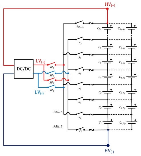
Figure 2.
S–P module (NS = number of series cells, NP = number of parallel cells).
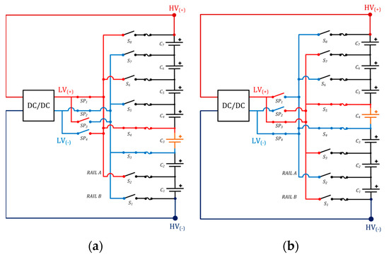
Figure 3.
7S1P module in detail: (a) balancing the third cell; (b) balancing the fourth cell.
A 7S1P module built with NMC cells resulting in 24 V of nominal voltage can be considered the standard building block for industrial and e-mobility applications, and they can be modularly connected in series to meet higher voltage level requirements, which are usually in multiples of 24, such as 48 V, 96 V, 120 V, 480 V, etc., for HV energy storage. In Figure 4, such an extended version is given. During the multimodule operation, the module switch pairs (SM1–SMNM) connect the power converter to the module top and bottom points, avoiding the entire pack HV level by floating connections. Two additional switches are required for each module, and as before, four switches (SP1–SP4) direct the correct polarity to the rails. The total number of switches is NM × (N + 3) + 4, where NM is the number of modules connected in series for intermodular balancing applications with more than one module, and N is the number of series cells in each module. As mentioned before, if the pack consists of a single module, then the number of switches is (N + 5).
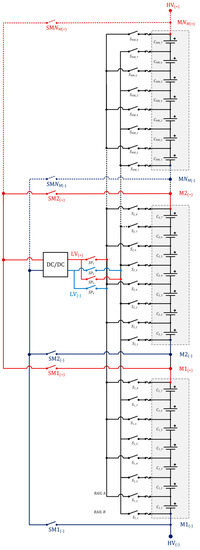
Figure 4.
Multimodule S–P configuration with modules connected in series (14S1P pack without the dashed lines).
Since the floating isolated converter is connected only to a single module at a time, and the input/output range is never exceeded, the number of cells and series connected modules that are interleaved by the converter can be increased as long as its isolation barrier is intact, and its input/output range covers the module voltage. In addition to a large pack that consists of separate modules, a direct cell-to-pack (CTP) and cell-to-chassis (CTC) assembly can also be balanced by dividing the whole pack into virtual modules without exceeding the limits of the power converter. This feature makes the presented architecture a reliable and feasible candidate for HV e-mobility, heavy duty EV, and HV stationary BESS applications with easily achievable converter properties, such as 1:2 or 1:4 input ranges and moderate step-up/step-down ratios, whereas isolated DC/DC converters with very wide input ranges and high step-up/step-down ratios are usually less efficient and costlier to manufacture. The experimental results of intermodular balancing in an HV configuration are presented in the next section.
2.2. P–S (Parallel of Series) Configuration
In the P–S configuration, pre-serialized S–P modules are stacked as parallel banks. The configuration is identified by the number of parallel and series connections as NpNs. The switched converter topology for this configuration is shown in Figure 5. Battery packs in P–S arrangement can be utilized in scalable stationary BESS for renewables, integrated grids, uninterrupted power supplies (UPS), and some specialized applications, such as telecommunications infrastructure, aerospace equipment, and naval systems, to provide redundancy, hot plugging, and scaling-up capabilities. As an example, retired modules can be removed from EVs and, after a mandatory safety and performance assessment, can be transferred to a stationary BESS site and connected to a DC bus of a matching voltage range in this fashion without modifying the already installed infrastructure. By directly reusing the retired modules, the tedious and dangerous process of disassembly and reassembly of the cells, which is usually impossible without damaging at least some of the original cells, can be avoided; the existing BMS circuitry in each module can be reused; and the total energy storage capacity can be increased modularly as needed. Even if the bus voltage is equal for all modules thanks to the parallel multimodule connection, any imbalance within one or more modules that can exist especially in second-life applications can still hinder the overall system performance since the safety limit will again be reached by the weakest cell. The proposed topology can also provide intermodular balancing in this case, the experimental results of which are presented in the next section. Moreover, if the potential difference between the modules is too high before hot plugging, to minimize the inrush current flowing between the packs and the main bus, a pre-balancing routine can be employed via the balancing connectors before the modules are actually connected to each other. The switched floating converter topology for P–S configuration is shown in Figure 5. The total number of switches is NP × (N + 1) + 4, where NP is the number of parallel modules, and N is the number of cells in series in each module. The same as the fundamental architecture, four switches (SP1–SP4) are used for polarity control.
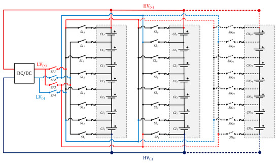
Figure 5.
Multimodule S–P configuration with modules connected in parallel (2P7S without the dashed lines).
2.3. Balancing Algorithm
For voltage-based balancing, the algorithm considers a pre-defined threshold, Vth,, in the order of millivolts and runs the AB routine until satisfying its termination criterion (1), i.e., when the voltage level of all cells converge within a band of (Vavg ± Vth), where Vavg is the average voltage, and ΔVmax is the maximum deviation from average.
First, as the main task of any BMS, the voltage of each cell is measured, and the cells are sorted. The average voltage and the cells with the minimum and maximum voltage values are determined. If there is more than one module in the pack, the modules are sorted as well. After checking the overall LIB for faults and enabling the switch matrix according to the desired direction, either the strongest module energy is transferred to the weakest cell in the pack, or the strongest cell energy is transferred to the weakest module until the threshold is reached. If there are other uneven cells with discrepancies, the process continues until all cell voltages are equalized. The excess energy is always redistributed from the strongest element to the weakest one that may exist in any location in the entire pack, eventually equalizing all cells and modules and achieving both intramodular and intermodular homogeneity. The balancing algorithm flowchart is depicted in Figure 6.
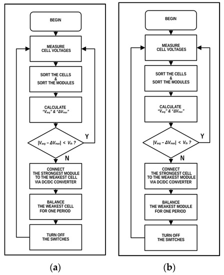
Figure 6.
The AB algorithm: (a) module-to-cell direction; (b) cell-to-module direction.
In general, the algorithm must ensure that both of the polarity switch pairs cannot be simultaneously enabled. If the pack consists of more than one series module, then the module switches must also conduct with respect to the algorithmic decision so that only a single module or cell provides energy at a time. A small delay for proper break-before-make operation must be used for all switches to avoid short circuit failures.
Despite being the most straightforward approach, voltage equalization may not necessarily provide charge equalization. SoC, which is usually expressed as a percentage, can be defined as the amount of available charge in the cell by
where Qnom is the nominal capacity in Ah and SoC0 is the initial value relative to the nominal capacity. If there exists an aging deviation and/or a temperature gradient within the pack, different SoC levels may have approximately the same voltage values due to altered capacity and impedance. This situation can lead to erroneous balancing decisions made by the controller, and continuing with the balancing operation can disturb the homogeneity even further. Therefore, an SoC-based AB is better suited for larger packs (3):
The disadvantage of this method is the need to precisely measure the balancing current in addition to the main pack current and to keep track of individual SoC values of all cells, which may occupy a considerably large amount of memory in an embedded microcontroller.
Within the scope of this research article, only the voltage-based balancing method was investigated. Nevertheless, aiming to provide an insight regarding the amount of charge that was balanced with respect to the initial and final voltage difference, the SoC values before and after the AB operation are still listed in tables. Several SoC estimation techniques are available [39,40,41,42]. The initial value can be found after establishing the SoC relationship by cell characterization experiments and then obtaining the reciprocal of open circuit voltage (OCV) using a look-up table or a cell model [43,44,45]. The experimental SoC–OCV curve of the cells that was used for linearly interpolating the OCV look-up table is given in Figure 7.
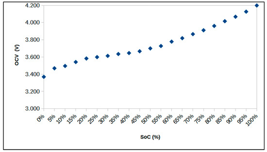
Figure 7.
The SoC–OCV curve of Samsung INR18650-20R cells.
3. Experimental Setup, Materials, and Component Selection
Regarding the hardware implementation, the main design criterion of AB balancing current had to be determined beforehand. Considering the nominal capacity of experimental cells Qnom = 2 Ah, it was chosen as at least to be ibal = 200 mA, corresponding to 0.1 C, a comparable value with the most commonly used dissipative passive balancing (PB) method. A current in the range of 50 mA to 250 mA is the de facto standard for commercial PB applications because the maximum power rating of the balancing resistors, which are most often the surface mount type, is usually less than 2 W. Two identical hardware prototypes were designed and built to accommodate and monitor two modules. One of them is shown in Figure 8. For repeatability, a list of all materials is presented below.
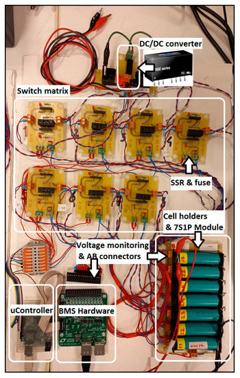
Figure 8.
The experimental test setup for a single 7S1P module.
Cells: The cells were INR18650-20R (Samsung SDIEM, Yongin, Republic of Korea), with 2000 mAh in nominal capacity. They were from the same manufacturing batch and purchased at the same time. The technical specifications are reported in Table 2 [46]. A custom printed circuit board (PCB) was designed with cell holders and balancing terminals for seven cells in series, forming a 24-V 7S1P module, and two of them were used to investigate different module combinations with a total of 14 cells.

Table 2.
Samsung INR18560-20R cell properties.
Switch matrix: To perform switching, CPC1218 (IXYS/Clare, Milpitas, CA, USA), a metal oxide semiconductor field effect transistor (MOSFET)-based solid-state relay (SSR) was preferred [47]. It has a built-in isolated gate drive, which is optically coupled to the bidirectional semiconductor switch and was therefore chosen to simplify the hardware implementation. Throughout this work the same SSR was used for all switching operations. A basic PCB was designed for two SSRs. As a safety measure, 750-mA fuses were installed between each switch and cell holder connection.
DC/DC converter: Since the focus of this article is to prove the concept of a switched converter AB topology, rather than the power converter itself, an off-the-shelf, isolated converter was selected to facilitate the realization of hardware implementation and investigate unidirectional (module-to-cell) energy flow. The DC isolation barrier rating, input/output isolation resistance, voltage input range, and voltage conversion ratio were important criteria. For a nominal module voltage of 24 V and a maximum balancing current of ibal = 400 mA, a small, low-cost 2-W DC/DC isolated converter, RSE-2405S/H2 (RECOM Power, Gmunden, Austria), with 18- to 36-V input and 5-V output, was deemed appropriate. The technical specifications can be found in Table 3 [48]. Since the output voltage is regulated but not adjustable, a limiting mechanism at the output side was necessary to protect both the cells and the power converter itself. The equivalent series resistance (ESR) of the switches, fuses, cell holder tabs, and wiring connections along the power path was measured to be approximately 2.5 Ω during conduction. This ESR provides sufficient current limiting.

Table 3.
Technical specifications of the DC–DC converter.
Cell monitor: Unlike measuring the voltage of a single independent cell, a special analog front end (AFE) circuitry is necessary to measure each voltage separately in the presence of high common mode voltage of a module comprising many cells connected in series. There are a few specialized integrated circuits (ICs) available on the market that encompass AFE, analog-to-digital conversion (ADC), PB, temperature measurement, and communication features. To fulfill the cell voltage measurement task, a commercial BMS IC from the LTC6804 (Linear Technology/Analog Devices Inc., Wilmington, MA, USA) series was used. It can measure the voltage of 12 cells with an accuracy of 1.1 mV and send the data via serial peripheral interface (SPI) bus [49]. Two units were connected together via the proprietary isoSPI bus to independently monitor each module of seven cells. Their sole purpose was cell voltage monitoring (at a data rate of 1 s/s) during AB; hence, the PB functionality was disabled.
Microcontroller: The microcontroller unit was an 8-bit, 16-Mhz ATMEGA328-based (Atmel/Microchip) Linduino (LT/ADI, Wilmington, MA, USA) platform [50]. Its tasks included communicating with the LTC6804 ICs via SPI, communicating with the PC via USB, running the state machine, and controlling the switches according to the balancing algorithm. The main reason for selecting a basic industrial 8-bit microcontroller was to verify the applicability of the presented online AB algorithm with the limited computational power and resources typically available with real-world commercial BMS hardware.
Other: A Fluke (Everett, WA, USA) 189 digital multimeter (DMM) was used for essential electrical measurements, and the consistency of cell voltage data transmitted by BMS ICs was checked by comparing the voltage values measured by DMM. A Chroma (Taoyuan City, Taiwan) 62050P programmable DC power supply and 63207 load were used for charging/discharging the cells and modifying cell voltages according to the experimental scenarios. Additionally, two GW-Instek (Taipei City, Taiwan) GPE 3321 DC power supplies were used for the verification of high voltage operation, which is detailed in the next section.
4. Results and Discussion
This section reports the experimental validation results of the proposed AB topology for all battery pack configurations, starting with the fundamental topology verification.
4.1. S–P Single Module (Intramodular) Balancing
For the fundamental experiment, the case of a single 24-V module in 7S1P configuration was investigated, as shown in Figure 2. The 24-V block was considered as a basis to verify the intramodular balancing capability. One of the seven cells had been previously discharged to a lower voltage than the other cells to create an imbalance scenario. The rest of the cell voltages were arranged to be as close as possible to each other. The threshold of voltage difference from the module average was set at Vth = 10 mV (1). The balancing period, Tbal, and the duty cycle, D, determine the balancing time, tbal, for each period (4). The AB period was set at 20 s with a 90% duty cycle, resulting in a balancing duration of 18 s. In Figure 9, AB during the first five periods is depicted in detail:
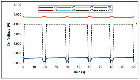
Figure 9.
Equalization during the first five periods of AB (CS = control signal).
First, according to the balancing algorithm, the cell with the minimum voltage was detected, and then the required cell and polarity switches were enabled to connect the output of the power converter to the weakest cell for the predefined switching period. The AB operation ended when its voltage value, V1, satisfied the termination condition. The initial and final module voltage values were 28.051 V and 27.881 V, respectively, whereas the initial and final average voltage values were 4007.2 mV and 3983.1 mV. The results are represented in Table 4, Table 5 and Figure 10.

Table 4.
The initial and final voltage values of 7S1P single module (intramodular AB).

Table 5.
The initial and final SoC estimation of 7S1P single module (intramodular AB).

Figure 10.
7S1P single module intramodular balancing (the fundamental topology): (a) cell voltage values; (b) the difference from module average.
4.2. P–S Multimodule (Intermodular) Balancing
After verifying intramodular AB within a single module, two 7S1P modules were connected in parallel to form a 2P7S pack of 24 V, as shown in Figure 5. This pack was built to investigate the equalization capability of uneven cells by intermodular balancing in a P–S configuration, in which inhomogeneity exists among the cells, even though the bus voltage is equal for all independent modules. The intermodular parallel balancing operation was validated with three unbalanced cells in module 1 (M1), all at different initial values, with the aim of simulating a serious imbalance condition at the lower part of the SoC range. The rest of the cell voltages in M1 and M2 were arranged so that both of the module voltages were approximately equal to each other before connecting them together.
After cell voltage sorting and detection of the weakest cell that had the minimum voltage in the entire pack, the required cell and polarity switches were enabled to connect the output of the power converter to the weakest cell, C17, accordingly. The first phase was completed when its voltage level, V17, reached the vicinity of V16, i.e., the cell with the second-highest initial deviation. Henceforward, the switched converter started transferring the pack energy to the new weakest cell with respect to the maximum voltage difference from the module average. The intermodular AB process continued with balancing all weak cells consecutively until the threshold was reached, after which all cell voltages in M1 were equalized. The average initial and final module voltage values, i.e., the parallel bus voltage, were 25.515 V and 25.404 V, respectively. The results are given in Figure 11 and Table 6 and Table 7.

Figure 11.
2P7S pack intermodular AB: (a) cell voltage values; (b) the difference from module average. (* imbalanced cells).

Table 6.
The initial and final voltage values of 2P7S pack with two modules (intermodular AB).

Table 7.
The initial and final SoC estimation of 2P7S pack with two modules (intermodular AB).
Considering the case of P–S packs, the imbalance cannot be detected if the BMS measures only the parallel bus voltage or the cell voltages of a single module; therefore, each parallel module must be monitored separately. Moreover, even with a restrictive threshold voltage of Vth = 10 mV, the maximum SoC deviation at the end of the AB routine was higher than that of the previous experiment. This result indicates the benefit of using an SoC-based algorithm, instead of voltage equalization, for better charge balancing and convergence, especially in the lower SoC region (<50%) for NMC or with chemistries, such as lithium–iron–phosphate (LFP), having a more flattened OCV curve along the whole SoC range.
4.3. S–P Multimodule (Intermodular) High Voltage Balancing
The HV experiment was aimed at investigating the intermodular AB capability of the presented architecture considering a pack configuration with many modules in series connection, which is also a valid test scenario for CTP and CTC pack construction if the continuous array of cells is virtually divided into modules. To this end, two 7S1P modules were serially connected with two 60-V DC power supplies between them, forming a pack of 178.8 V, as illustrated in Figure 12. One of the cells in each module was imbalanced, while the rest of them had very small discrepancies. The M1 voltage was altered to be lower than that of M2 with the purpose of establishing an imbalance situation between the modules as well. The total voltage of the DC power supplies was 120 V, emulating five balanced 24-V modules connected in series. By this experimental setup, the AB operation between two extreme modules across a 49S1P HV pack consisting of seven 24-V modules could be elaborated. The threshold voltage was set at Vth = 6 mV for a more stringent AB.
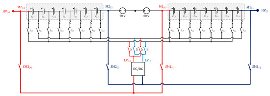
Figure 12.
HV intermodular AB (49S1P pack with emulation).
After module sorting and determination of the weakest cell in the HV pack, the input port of the switched converter was connected to M2, i.e., the strongest module with the highest voltage, via module selection switches to transfer its excess energy to the cells in M1. First, the cell with the maximum voltage deviation in M1, V11, was balanced until the threshold voltage was reached. In the second phase, the voltage of the weakest cell in M2, V21, was balanced until the homogeneity in M2 was achieved with respect to its own module average. After ensuring the intramodular balance for both modules, the switched converter continued redistributing the excess energy from M2 to the cells in M1 one by one until satisfying the termination condition, eventually equalizing all cell voltages in independent modules as well. Thus, HV pack level AB was fulfilled by means of intermodular charge transfer from the strongest module, as presented in Figure 13 and Table 8 and Table 9.

Figure 13.
HV pack intermodular AB: (a) cell voltage values; (b) the difference from pack average. (* imbalanced cells).

Table 8.
The initial and final voltage values of HV pack with two modules (intermodular AB).

Table 9.
The initial and final SoC estimation of HV pack with two modules (intermodular AB).
4.4. AB Verification under Load
All of the above experiments were carried out to verify AB operations when the modules were idle; i.e., no load was present. To demonstrate the complete operational capability of the proposed AB architecture, the S–P and P–S modules were subjected to a significant load current as well. With this experiment, a scenario in which adequate idling time may not be available for full equalization before energy delivery can also be tested.
First, the 7S1P configuration with one imbalanced cell in the same fundamental AB test setup was investigated. The AB algorithm was disabled, and a constant current (CC) load of 2000 mA (1.0 C) was applied until the weakest cell reached the predefined discharge cut-off voltage limit of 2700 mV, as presented in Figure 14a. The runtime was found to be t = 2195 s with energy delivery of E = 30.562 Wh, according to the trapezoidal integration (5)
where V is the module voltage, and I is the load current. Then, the discharged cells were exchanged with a second set of identical cells, the voltages of which had been previously arranged to be as close as possible to the initial voltage values of the first set. After applying the same load current while the AB algorithm was functional, the runtime extended to t’ = 2564 s, as shown in Figure 14c. The delivered energy was calculated to be E’ = 35.279 Wh, resulting in 16.8% extra duration and 15.4% additional energy.
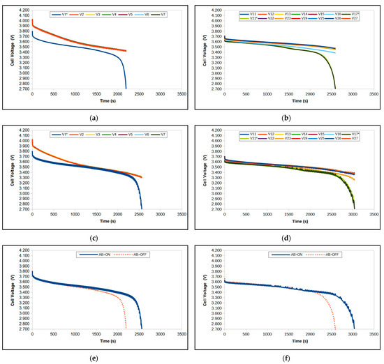
Figure 14.
AB operation under a 2-A load current; (a,c) 7S1P without and with AB; (b,d) 2P7S without and with AB; (e,f) direct comparison of 7S1P and 2P7S packs without and with AB. (* imbalanced cells).
For the 2P7S configuration, the same procedure was repeated with one imbalanced cell in each parallel module, similar to the second idle AB experimental setup in the lower SoC range. A CC load of 2000 mA (0.5 C per module) was applied until the weakest cell reached the cut-off. The runtime was extended from t = 2592 s to t’ = 3037 s, whereas the amount of energy increased from E = 35.748 Wh to E’ = 41.414 Wh, yielding a 16.9% longer duration and 15.8% more energy delivered to the load. The resulting graphs are depicted in Figure 14 and Table 10. In addition, the detail of intermodular AB operation and its ability to support both of the weak cells consecutively during discharge is shown in Figure 15, demonstrating the last 10 balancing periods before cut-off.

Table 10.
The comparison of 7S1P and 2P7S pack performance with and without AB.
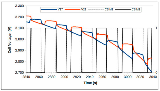
Figure 15.
Intermodular AB operation during the last 10 periods (7P2S pack, CS = control signal).
5. Conclusions
In this proof-of-concept study, a flexible intermodular AB architecture was presented, and its practical applicability was validated by commercial BMS hardware implementation with an online balancing algorithm. The switched (flying) converter topology can perform both intramodular and intermodular AB at the pack level without requiring multiple converters or auxiliary accumulators. Moreover, it is capable of redistributing the excess energy from any module to any cell, and vice versa, both in series-connected (S–P) and parallel-connected (P–S) pack configurations. Theoretically, the number of cells and modules is only limited by the input/output isolation rating of the converter. Thus, the proposed architecture can be considered a promising AB approach to mitigate the cellular and modular inhomogeneity of HV packs that consist of the many modules typically necessary in heavy-duty EV and high energy BESS applications. It is also possible to be used in packs with direct CTP and CTC construction by organizing virtual modules with respect to the input/output specifications of the switched converter. In addition, HEV and aerospace applications with strict volume and weight restrictions may also benefit from the reduced component count.
The performance of the intermodular architecture was extensively investigated in various realistic S–P and P–S pack configurations. For all scenarios, the online balancing algorithm was able to equalize the cells and modules successfully in terms of voltage homogeneity in idle mode, including an HV pack of 49S1P configuration. When the imbalanced packs were subjected to load current, it was also possible to redistribute the pack energy and provide an extended runtime by supporting the weak cells during discharge. The discharge duration and energy output were increased by >5% in both the 7S1P and 2P7S packs.
The main drawback of employing a single switched DC/DC converter instead of using a dedicated one for each cell is the increased total balancing time if a large number of uneven cells initially exist because the converter must traverse the entire pack to balance a single cell at a time. The outlook includes the design of an SoC-based real-time controller with current optimization, which can increase the overall efficiency and/or decrease the total balancing time since the online AB algorithm in this paper runs in basic on–off control mode without any optimization routines. The experiments were carried out only in the module-to-cell direction, i.e., unidirectional energy flow. The design and implementation of a bidirectional isolated DC/DC converter with features such as wide input and output ranges, high efficiency, low quiescent current, high accuracy load/line regulation, and low ripple remains an open power electronics topic for future work of the authors. This topology can also be used as a balancer for SC banks in hybrid energy management applications, which will be investigated in another future study.
Author Contributions
Conceptualization, A.B.; methodology, A.B. and M.C.; validation, M.C.; investigation, M.C.; writing—original draft preparation, M.C.; visualization, M.C.; supervision, A.B. All authors have read and agreed to the published version of the manuscript.
Funding
This research received no external funding.
Data Availability Statement
Not applicable.
Acknowledgments
The authors would like to thank the anonymous reviewers for improving the quality of the manuscript.
Conflicts of Interest
The authors declare no conflict of interest.
Abbreviations
The following abbreviations are used in this research
| AB | Active Balancing |
| ADC | Analog to Digital Converter |
| AFE | Analog Front End |
| BESS | Battery Energy Storage System |
| BMS | Battery Management System |
| C | C-rate |
| CTC | Cell-to-Chassis Construction |
| CTP | Cell-to-Pack Construction |
| DC | Direct Current |
| DG | Distributed Generation |
| DMM | Digital Multimeter |
| DPDT | Double-Pole Double-Throw |
| ΔSOCmax | Maximum State of Charge Deviation |
| ΔVmax | Maximum Voltage Deviation |
| ESR | Equivalent Series Resistance |
| ESS | Energy Storage System |
| EV | Electric Vehicle |
| H/EV | Hybrid/Electric Vehicle |
| HV | High Voltage |
| IC | Integrated Circuit |
| LFP | Lithium–Iron–Phosphate |
| LIB | Lithium–Ion Battery |
| MOSFET | Metal–Oxide Semiconductor Field Effect Transistor |
| NMC | Nickel–Manganese–Cobalt |
| OCV | Open Circuit Voltage |
| OV | Over-Voltage |
| PB | Passive Balancing |
| PC | Personal Computer |
| PCB | Printed Circuit Board |
| P–S | Parallel Connection of Series Cells |
| Qnom | Nominal Capacity |
| REP | Renewable Energy Plant |
| SC | Super Capacitor |
| SoC | State of Charge |
| SoCavg | Average State of Charge Value |
| SoCmin | Minimum State of Charge Value (Module SoC) |
| SoCth | State of Charge Threshold for Balancing |
| S–P | Series Connection of Parallel Cells |
| SPI | Serial Peripheral Interface |
| UPS | Uninterrupted Power Supply |
| UV | Under-Voltage |
| USB | Universal Serial Bus |
| Vth | Voltage Threshold for Balancing |
| Vavg | Average Voltage Value |
References
- Ackermann, T.; Andersson, G.; Söder, L. Distributed generation: A definition. Electr. Power Syst. Res. 2001, 57, 195–204. [Google Scholar] [CrossRef]
- Gozel, T.; Hocaoglu, M.H.; Eminoglu, U.; Balikci, A. Optimal placement and sizing of distributed generation on radial feeder with different static load models. In Proceedings of the 2005 International Conference on Future Power Systems, Amsterdam, The Netherlands, 18 November 2005; pp. 2–6. [Google Scholar] [CrossRef]
- Chen, H.; Cong, T.N.; Yang, W.; Tan, C.; Li, Y.; Ding, Y. Progress in electrical energy storage system: A critical review. Prog. Nat. Sci. 2009, 19, 291–312. [Google Scholar] [CrossRef]
- Oskouei, M.Z.; Seker, A.A.; Tuncel, S.; Demirbas, E.; Gozel, T.; Hocaoglu, M.H.; Abapour, M.; Mohammadi-Ivatloo, B. A Critical Review on the Impacts of Energy Storage Systems and Demand-Side Management Strategies in the Economic Operation of Renewable-Based Distribution Network. Sustainability 2022, 14, 2110. [Google Scholar] [CrossRef]
- Di Piazza, M.C.; Luna, M.; La Tona, G.; Di Piazza, A. Energy Management of Hybrid PV-Storage Systems for Improved Grid Integration. In Proceedings of the IEEE International Conference on Environment and Electrical Engineering and IEEE Industrial and Commercial Power Systems Europe (EEEIC/I&CPS Europe), Milan, Italy, 6–9 June 2017; pp. 1–5. [Google Scholar] [CrossRef]
- Hesse, H.C.; Kumtepeli, V.; Schimpe, M.; Reniers, J.; Howey, D.A.; Tripathi, A.; Wang, Y.; Jossen, A. Ageing and Efficiency Aware Battery Dispatch for Arbitrage Markets Using Mixed Integer Linear Programming. Energies 2019, 12, 999. [Google Scholar] [CrossRef]
- Di Piazza, M.C.; Luna, M.; La Tona, G. A Survey of Energy Management Systems Considering Battery State of Health Preservation in Microgrid Applications. In Lecture Notes in Electrical Engineering; Springer: Berlin/Heidelberg, Germany, 2023; p. 993. [Google Scholar] [CrossRef]
- Sepulveda, N.A.; Jenkins, J.D.; Edington, A.; Mallapragada, D.S.; Lester, R.K. The design space for long-duration energy storage in decarbonized power systems. Nat. Energy 2021, 6, 506–516. [Google Scholar] [CrossRef]
- Luna, M.; La Tona, G.; Accetta, A.; Pucci, M.; Pietra, A.; Di Piazza, M.C. Optimal Management of Battery and Fuel Cell-Based Decentralized Generation in DC Shipboard Microgrids. Energies 2023, 16, 1682. [Google Scholar] [CrossRef]
- Widyantara, R.D.; Zulaikah, S.; Juangsa, F.B.; Budiman, B.A.; Aziz, M. Review on Battery Packing Design Strategies for Superior Thermal Management in Electric Vehicles. Batteries 2022, 8, 287. [Google Scholar] [CrossRef]
- Pampel, F.; Pischinger, S.; Teuber, M. A systematic comparison of the packing density of battery cell-to-pack concepts at different degrees of implementation. Results Eng. 2021, 13, 100310. [Google Scholar] [CrossRef]
- Kampker, A.; Heimes, H.H.; Offermanns, C.; Vienenkötter, J.; Robben, T. Framework and Classification of Battery System Architectures. World Electr. Veh. J. 2023, 14, 88. [Google Scholar] [CrossRef]
- Belingardi, G.; Scattina, A. Battery Pack and Underbody: Integration in the Structure Design for Battery Electric Vehicles—Challenges and Solutions. Vehicles 2023, 5, 498–514. [Google Scholar] [CrossRef]
- Waag, W.; Fleischer, C.; Sauer, D.U. Critical review of the methods for monitoring of lithium-ion batteries in electric and hybrid vehicles. J. Power Sources 2014, 258, 321–339. [Google Scholar] [CrossRef]
- Liu, W.; Placke, T.; Chau, K.T. Overview of batteries and battery management for electric vehicles. Energy Rep. 2022, 8, 4058–4084. [Google Scholar] [CrossRef]
- Baumhöfer, T.; Brühl, M.; Rothgang, S.; Sauer, D.U. Production caused variation in capacity aging trend and correlation to initial cell performance. J. Power Sources 2014, 247, 332–338. [Google Scholar] [CrossRef]
- Zilberman, I.; Schmitt, J.; Ludwig, S.; Naumann, M.; Jossen, A. Simulation of voltage imbalance in large lithium-ion battery packs influenced by cell-to-cell variations and balancing systems. J. Energy Storage 2020, 32, 101828. [Google Scholar] [CrossRef]
- Schindler, M.; Sturm, J.; Ludwig, S.; Schmitt, J.; Jossen, A. Evolution of initial cell-to-cell variations during a three-year production cycle. eTransportation 2021, 8, 100102. [Google Scholar] [CrossRef]
- Beck, D.; Dechent, P.; Junker, M.; Sauer, D.U.; Dubarry, M. Inhomogeneities and cell-to-cell variations in lithium-ion batteries, a review. Energies 2021, 14, 3276. [Google Scholar] [CrossRef]
- Hopkins, D.C.; Mosling, C.R.; Hung, S.T. The Use of Equalizing Converters for Serial Charging of Long Battery Strings. In Proceedings of the Applied Power Electronics Conference APEC, Dallas, TX, USA, 10–15 March 1991; pp. 493–498. [Google Scholar]
- Pascual, C.; Krein, P.T. Switched capacitor system for automatic series battery equalization. In Proceedings of the Applied Power Electronics Conference, Atlanta, GA, USA, 27 February 1997; pp. 848–854. [Google Scholar]
- Moore, S.W.; Schneider, P.J. A Review of Cell Equalization Methods for Lithium Ion and Lithium Polymer Battery Systems; SAE Technical Paper 2001-01-0959; Society of Automotive Engineers (SAE): London, UK, 2001. [Google Scholar]
- Cao, J.; Schofield, N.; Emadi, A. Battery Balancing Methods: A Comprehensive Review. In Proceedings of the IEEE Vehicle Power and Propulsion Conference VPPC, Harbin, China, 3–5 September 2008. [Google Scholar]
- Carter, J.; Fan, Z.; Cao, J. Cell equalisation circuits: A review. J. Power Sources 2020, 448, 227489. [Google Scholar] [CrossRef]
- Cassani, P.A.; Williamson, S.S. Significance of battery cell equalization and monitoring for practical commercialization of plug-in hybrid electric vehicles. In Proceedings of the Applied Power Electronics Conference APEC, Washington, DC, USA, 15–19 February 2009; pp. 465–471. [Google Scholar]
- Yuanmao, Y.; Cheng, K.W.E.; Yeung, Y.P.B. Zero-current switching switched-capacitor zero-voltage-gap automatic equalization system for series battery string. IEEE Trans. Power Electron. 2012, 27, 3234–3242. [Google Scholar] [CrossRef]
- Einhorn, M.; Guertlschmid, W.; Blochberger, T.; Kumpusch, R.; Permann, R.; Conte, F.V.; Kral, C.; Fleig, J. A current equalization method for serially connected battery cells using a single power converter for each cell. IEEE Trans. Veh. Technol. 2011, 60, 4227–4237. [Google Scholar] [CrossRef]
- Olalla, C.; Clement, D.; Rodriguez, M.; Maksimovic, D. Architectures and control of submodule integrated DC–DC converters for photovoltaic applications. IEEE Trans. Power Electron. 2013, 28, 2980–2997. [Google Scholar] [CrossRef]
- Costinett, D.; Hathaway, K.; Rehman, M.U.; Evzelman, M.; Zane, R.; Levron, Y.; Maksimovic, D. Active balancing system for electric vehicles with incorporated low voltage bus. In Proceedings of the Applied Power Electronics Conference and Exposition APEC, Fort Worth, TX, USA, 16–20 March 2014; pp. 3230–3236. [Google Scholar]
- Gallardo-Lozano, J.; Romero-Cadaval, E.; Milanes-Montero, M.I.; Guerrero-Martinez, M.A. Battery equalization active methods. J. Power Sources 2014, 246, 934–949. [Google Scholar] [CrossRef]
- Baronti, F.; Roncella, R.; Saletti, R. Performance comparison of active balancing techniques for lithium-ion batteries. J. Power Sources 2014, 267, 603–609. [Google Scholar] [CrossRef]
- Guo, X.; Kang, L.; Huang, Z.; Yao, Y.; Yang, H. Research on a novel power inductor-based bidirectional lossless equalization circuit for series-connected battery packs. Energies 2015, 8, 5555–5576. [Google Scholar] [CrossRef]
- Pinto, C.; de Castro, R.; Barreras, J.V.; Araújo, R.E.; Howey, D.A. Smart Balancing Control of a Hybrid Energy Storage System Based on a Cell-to-Cell Shared Energy Transfer Configuration. In Proceedings of the IEEE Vehicle Power and Propulsion Conference (VPPC), IEEE Transactions on Vehicular Technology VPPC, Chicago, IL, USA, 27–30 August 2018; pp. 1–6. [Google Scholar]
- Pozzi, A.; Zambelli, M.; Ferrara, A.; Raimondo, D.M. Balancing-aware charging strategy for series-connected lithium-ion cells: A nonlinear model predictive control approach. IEEE Trans. Control Syst. Technol. 2020, 28, 1862–1877. [Google Scholar] [CrossRef]
- Farhangi, B.; Toliyat, H.A. Modeling and Analyzing Multiport Isolation Transformer Capacitive Components for Onboard Vehicular Power Conditioners. IEEE Trans. Ind. Electron. 2014, 62, 3134–3142. [Google Scholar] [CrossRef]
- Pereira, T.; Hoffmann, F.; Zhu, R.; Liserre, M. A Comprehensive Assessment of Multiwinding Transformer-Based DC–DC Converters. IEEE Trans. Power Electron. 2021, 36, 10020–10036. [Google Scholar] [CrossRef]
- Zhang, Z.; Ouyang, Z.; Thomsen, O.C.; Andersen, M.A.E. Analysis and Design of a Bidirectional Isolated DC–DC Converter for Fuel Cells and Supercapacitors Hybrid System. IEEE Trans. Power Electron. 2012, 27, 848–859. [Google Scholar] [CrossRef]
- Raghavendra, K.V.G.; Zeb, K.; Muthusamy, A.; Krishna, T.N.V.; Kumar, S.V.S.V.P.; Kim, D.-H.; Kim, M.-S.; Cho, H.-G.; Kim, H.-J. A Comprehensive Review of DC–DC Converter Topologies and Modulation Strategies with Recent Advances in Solar Photovoltaic Systems. Electronics 2020, 9, 31. [Google Scholar] [CrossRef]
- Chen, Z.; Zhou, J.; Zhou, F.; Xu, S. State-of-charge estimation of lithium-ion batteries based on improved H infinity filter algorithm and its novel equalization method. J. Clean. Prod. 2020, 290, 125180. [Google Scholar] [CrossRef]
- Han, W.; Zhang, L.; Han, Y. Computationally efficient methods for state of charge approximation and performance measure calculation in series-connected battery equalization systems. J. Power Sources 2015, 286, 145–158. [Google Scholar] [CrossRef]
- Piller, S.; Perrin, M.; Jossen, A. Methods for state-of-charge determination and their applications. J. Power Sources 2001, 96, 113–120. [Google Scholar] [CrossRef]
- Peng, J.; Meng, J.; Chen, D.; Liu, H.; Hao, S.; Sui, X.; Du, X. A Review of Lithium-Ion Battery Capacity Estimation Methods for Onboard Battery Management Systems: Recent Progress and Perspectives. Batteries 2022, 8, 229. [Google Scholar] [CrossRef]
- Chen, M.; Rincon-Mora, G.A. Accurate Electrical Battery Model Capable of Predicting Runtime and I–V Performance. IEEE Trans. Energy Convers. 2006, 21, 504–511. [Google Scholar] [CrossRef]
- Ceylan, M.; Cengiz, E.; Demir-Cakan, R.; Balikci, A. A Novel Lithium-Sulphur Battery Model for Automotive and Renewable Energy Applications. In Proceedings of the Advanced Battery Power Conference/Kraftwerk Batterie, Aachen, Germany, 27–29 April 2015. [Google Scholar] [CrossRef]
- Ceylan, M.; Balikci, A. A Temperature Dependent Model for LTO/NMC Batteries. ECS Trans. 2019, 95, 113. [Google Scholar] [CrossRef]
- INR18650-20R Cell Specification of Product; V1.2; Samsung SDI: Yongin, Republic of Korea, 2011.
- CPC1218 Datasheet; Rev. 6; IXYS: Milpitas, CA, USA, 2012.
- RSE Series Datasheet; Rev. 4; RECOM Power: Gmunden, Austria, 2020.
- LTC6804-1/LTC6804-2 Multicell Battery Monitors Datasheet; Rev. C; Analog Devices Incorporated: Wilmington, MA, USA, 2016.
- Linduino Datasheet; Rev. C; Analog Devices Incorporated: Wilmington, MA, USA, 2016.
Disclaimer/Publisher’s Note: The statements, opinions and data contained in all publications are solely those of the individual author(s) and contributor(s) and not of MDPI and/or the editor(s). MDPI and/or the editor(s) disclaim responsibility for any injury to people or property resulting from any ideas, methods, instructions or products referred to in the content. |
© 2023 by the authors. Licensee MDPI, Basel, Switzerland. This article is an open access article distributed under the terms and conditions of the Creative Commons Attribution (CC BY) license (https://creativecommons.org/licenses/by/4.0/).