Article

Decentralized Emergency Control of AC Power Grid Modes with Distributed Generation

1
Department of Automated Electric Power Systems, Novosibirsk State Technical University, Novosibirsk 630073, Russia
2
Department of Power Plants, Novosibirsk State Technical University, Novosibirsk 630073, Russia
3
Department of Automated Electrical Systems, Ural Federal University, Yekaterinburg 620002, Russia
4
Faculty of Electrical and Environmental Engineering, Riga Technical University, 1048 Riga, Latvia
*
Author to whom correspondence should be addressed.
Energies 2023, 16(15), 5607; https://doi.org/10.3390/en16155607
Submission received: 27 June 2023 / Revised: 19 July 2023 / Accepted: 24 July 2023 / Published: 25 July 2023
(This article belongs to the Section A: Sustainable Energy)

Abstract

:
Large-scale development of small-scale generation, and facilities based on this, with their integration into existing distribution networks, qualitatively change the modes and tasks of network management and transform previously passive electric networks into active ones. Features of parameters and modes of small-scale generation, insufficient observability and manageability in centralized management determine the need to use a decentralized multi-agent control of the modes of such networks. First of all, this applies to emergency management, which includes automatic restoration of the integrity and normal operation of the network. This paper presents a set of specialized methods for emergency management of active power grid modes and the results of a study of their effectiveness on mathematical and physical models that confirm the feasibility of using decentralized emergency management and network recovery management. In particular, this includes: a method of emergency proactively balanced separation of grid energy districts along one of the a priori fixed network cross-sections in the event of disturbances with the transition to island mode, and a method for two-stage restoration of the integrity and normal network mode with decentralized synchronization of active parts on remote network switches. In the case of the decentralized remote synchronization of active parts, it is proposed to use special control of the excitation and speed of generators to create conditions for the successful operation of automatic reclosing devices with synchronization detection. It is essential for emergency management in active networks with small generation to reject the concept of ensuring the reliability of power supply through maintaining the integrity of the network in favor of the concept of an emergency-balanced breakdown of the network into balanced areas with the subsequent automatic restoration of integrity. To conduct research on the physical model, a prototype of distributed system emergency automation has been developed that does not use data transmission tools, which ensures its high cybersecurity and the feasibility of decentralized management.

1. Introduction

An undoubted achievement in creating reliable electric power systems is the development of their effective systems of centralized operational and automatic emergency management. To date, we can talk about a fairly advanced technology for centralized management of power system modes, provided with technical means, qualified personnel, and a regulatory framework; however, its ability to adapt to modern conditions for the development of the electric power industry is almost exhausted [1,2].
In modern conditions, with the weakening of centralized management of the development of the electric power industry, changes in public relations, value orientations, environmental restrictions, and conditions for ensuring energy security, the shortcomings have become more acute and the inadequacy of this concept in the new conditions for the existence of the electric power industry has become apparent:
  • The need for a developed electric grid for transmission and distribution of energy from its remote large sources leads to unjustified losses of generated electricity and costs for the creation and operation of electric networks. Suffice it to say that the network component in the cost of electricity for consumers reaches half, and the total losses of electricity during its transmission and distribution reach 20%.
  • The inability to fully use thermal energy at large fuel-fired power plants remote from consumers leads to the predominant use of condensing thermal power plants with a useful fuel use of about 40%, instead of the possible 80–90% at thermal power plants with a combined useful heat and electricity generation.
  • Long construction and payback periods for large generating and grid facilities (20–25 years) are not very attractive for investors who focus on 5–7 years and their implementation through investment components in electricity tariffs lead to their growth and decreases in the standard of living of the population and the competitive ability of the national economy.
  • Focusing on the use of large power plants leads to ignoring small, diverse energy resources, including renewable resources, located close to energy consumers, the use of which significantly reduces losses during energy transmission.
  • Orientation to the use of large power plants leads to monofunctionality of the power industry, limiting its purpose to energy supply to consumers, in contrast to the polyfunctionality that occurs in multi-purpose energy production when solving complex problems (energy production at waste-burning and waste-recycling power plants, when integrating energy production into the production cycles of enterprises by using associated and bio-gases).
  • The increasing complexity of the tasks of managing the modes of electric power systems as they develop also leads to the complexity of the information and control system, the need for its deep digitalization, which increases vulnerability to cyber attacks within the framework of a centralized control system, and the dependence of the reliability of power supply on the reliability of systems and control centers.
  • It should also be noted that time has dictated a sharp increase in the requirements for the survivability of power systems in the face of various external influences, to which exclusively centralized power supply and control systems respond to a small extent due to their structural vulnerability.
It is promising to abandon centralized dispatching, regime and emergency management with a transition to a decentralized multi-agent one that does not use a hierarchy and provides greater freedom in making decisions to achieve their own goals for different actors in the implementation of the general network mode.
Currently, multi-agent management systems are widely researched and actively implemented in distribution networks. We consider the work of a representative number of researchers in this area.
In [3,4], McArthur et al. considered fundamental concepts and approaches in the field of creating multi-agent systems that are used in the power industry. They provided recommendations on the design and implementation of this technology in the energy sector.
The authors of [5,6,7,8] provide an overview of the concept of agents and multi-agent systems, as well as reviews of recent studies on the use of multi-agent systems in microgrid control systems.
Dou et al. [9] consider the problem of multi-agent voltage control in an autonomous microgrid. The management scheme consists of several agents, in particular an upper-level energy management agent, several middle-level agents, and many lower-level management agents. It is noted that such a control system contributes to the optimal level of voltage in the network and the maximum economic effect of electricity generation by small-scale generation facilities. Its development is discussed in [10], in which a four-level management system is proposed to improve the economic and dynamic indicators of the system.
The work of Abdulmohsen et al. [11] is devoted to multi-agent energy management in isolated microgrids. A two-stage energy management strategy is considered. At the first stage, when the microgrid works in parallel with the network, the central agent performs operational planning of the amount of generated power in case of a transition to an island mode. In the second stage, when an island mode is detected, agents work together to quickly balance the microgrid if the actual operating parameters of the mode differ from the predicted ones.
In their study, Nguyen et al. [12] proposed a method for controlling the frequency and voltage of storage devices, in which agents, measuring local parameters, interact with other agents in order to maintain their operating parameters and the charge level of local storage devices. He et al. [13] solved the problem of frequency normalization, which is subject to external interference when agents communicate over communication channels.
A multi-agent microgrid control structure in different modes, in particular, when separating into island mode, as well as for synchronizing and enabling the parallel operation of several microgrids with an external network in order to provide auxiliary services, was considered by Cintuglu et al. [14].
Kumar et al. [15] proposed a two-level architecture for managing objects of distributed generation of several microgrids to achieve an economic effect. The paper considers the trade of electricity between agents of generation facilities, loads, storage devices, and an external network agent.
Dimeas et al. [16] reviewed the strategy of a microgrid’s participation in the energy market. Foo et al. [17] presented an approach in which agents interact with each other on pre-defined tasks to achieve local and global goals in the market trade of electricity.
In the work of Ren et al. [18], an attempt was made by agents of different levels to implement a decentralized recovery after an emergency division into parts of the unified power system. According to the proposed method, the number of agents in normal modes is minimal, and in post-accident modes, many agents are involved to restore the integrity of the system.
Bulatov et al. [19,20] proposed and modeled a single-level multi-agent voltage regulation system in the event of disturbances in an electrical network with distributed generation. The system made it possible to compensate for the resulting voltage drop in the network when connecting a powerful load, as well as in the event of short circuits.
The authors of [21] present the structure of a multi–agent system in which agents, in particular, a coordinator agent, a diagnostic agent, an identification agent, an executive agent, etc., adapt to changing conditions, which makes it possible to effectively use this technology for building active-adaptive networks.
Islam et al. [22] proposed a multi-agent scheme for emergency management under multiple emergency disturbances. It is noted that management based on a decentralized architecture of intelligent agents can provide fast and efficient support for the voltage level in the system. Similar control for voltage regulation in normal and emergency modes was proposed by Sheng et al. [23], and Panasetsky et al. [24] proposed a control system that provides the coordination of various devices to prevent power supply disconnection in post-emergency mode.
Logenthiran et al. [25] present a digital simulator for a microgrid that works in real time with a multi-agent system for managing generation and consumption processes. In it, agents plan in two stages; one day ahead and one in real time. It is noted that this solution allows the microgrid to maximize power generation, minimize operating costs, and optimize energy exchange when working with an external network. Davidson et al. [26,27] demonstrated the possibility of using multi-agent systems technology to automate SCADA data analysis and digital accident recorders.
It follows from the presented review that, despite a lot of ongoing research, multi-agent management systems, as a rule, actively use communication channels for agent communication, which undoubtedly creates a vulnerability of management systems and their high cost. In addition, the solution of the problem of complex decentralized management of active network modes has not yet been considered.
The technical advantage of decentralized management is an increase in cybersecurity, the absence of the need for a developed telecommunications network, specialized expensive dispatch control centers, and centralized emergency management systems.
The purpose of this article is to present the possibilities of creating reliable active electric networks with multiple distributed generation and objects based on it without centralized mode management.
It should be noted that the presented technology has already been partially implemented at existing facilities, as well as fully tested on mathematical and physical electrodynamic models of power systems.

2. Methodology

2.1. General Provisions

The commonality of the electrical mode of all elements operating in the electric network determines the habitual need to centralize its operational, regime and emergency management. Centralization ensures security, observability, manageability, and optimality of the power grid mode; however, its disadvantages are the high cost of the data collection and transmission system, cyber vulnerability, and subordination of subjects working in the network to the general goals and criteria of a centralized management system.
It should be noted that the mode of the electric network has a complex nature and is divided into a certain set of classes when controlling it:
  • By parameter behavior—steady-state or transient;
  • According to the compliance of parameters with various requirements—normal, emergency, or post-accident;
  • By nature—stable or unstable.
For each of the classes of modes, the general control system has many subsystems that solve both general (system) and private (local) tasks, while the subsystems themselves use both centralized and decentralized construction structures. The management structure of the system as a whole, as well as its subsystems, should be considered centralized if it has a single decision-making center that uses a data exchange system with subordinate centers.
In the focus of decentralizing emergency management, we will consider the main system problems of managing the general mode of an electric network with distributed generation with their centralized and decentralized solutions:
  • Emergency management for large disturbances of the normal mode;
  • Maintaining the efficiency of the power supply system in post-accident conditions;
  • Restore the integrity and normal operation of the network after an emergency or emergency breakdown.
When developing a system of decentralized multi-agent management of electric grid modes, we will take the following management principles as axioms:
  • Independent decision-making by each agent within the limits of its authority and general rules of conduct.
  • Unity and mandatory compliance with the general rules for making decisions and actions by agents.
  • Maximize the use of local information about the state of the managed system (electric power system mode) by each agent when making decisions.
  • Prioritization of decision-making criteria and actions of agents to eliminate violations of the normal regime over decisions to manage normal regimes.
  • Limited freedom of action of agents in normal modes by creating violations of the normal mode and conditions for the impossibility of effective actions of agents in adjacent areas.
At the same time, for the unambiguous perception of decentralized (multi-agent) management, it is necessary to present the main terms that define its content:
An active electric network with distributed (small) generation—a distribution electric network with many sources and objects with low-power electric energy sources included in different nodes of the network.
Agent (in general)—an entity (person, automation, etc.) that acts on behalf (in the interests and according to the rules) of any subject (consumer, enterprise, etc.).
Multi-agent management system (MAS) is a management system that operates through the interaction of intelligent agents.
A decentralized multi-agent management system (DMAS) is a multi–agent management system that operates through the interaction of intelligent agents of the same level without exchanging information between them, using local information about the state of the control object.
A mono-multi-agent management system (MMAS) is a management system that functions through the interaction of intelligent agents of one entity acting in its interests and according to its rules.
A poly-multi-agent management system (PMAS) is a management system that functions through the interaction of intelligent agents of multiple entities acting in their interests, but according to general rules.

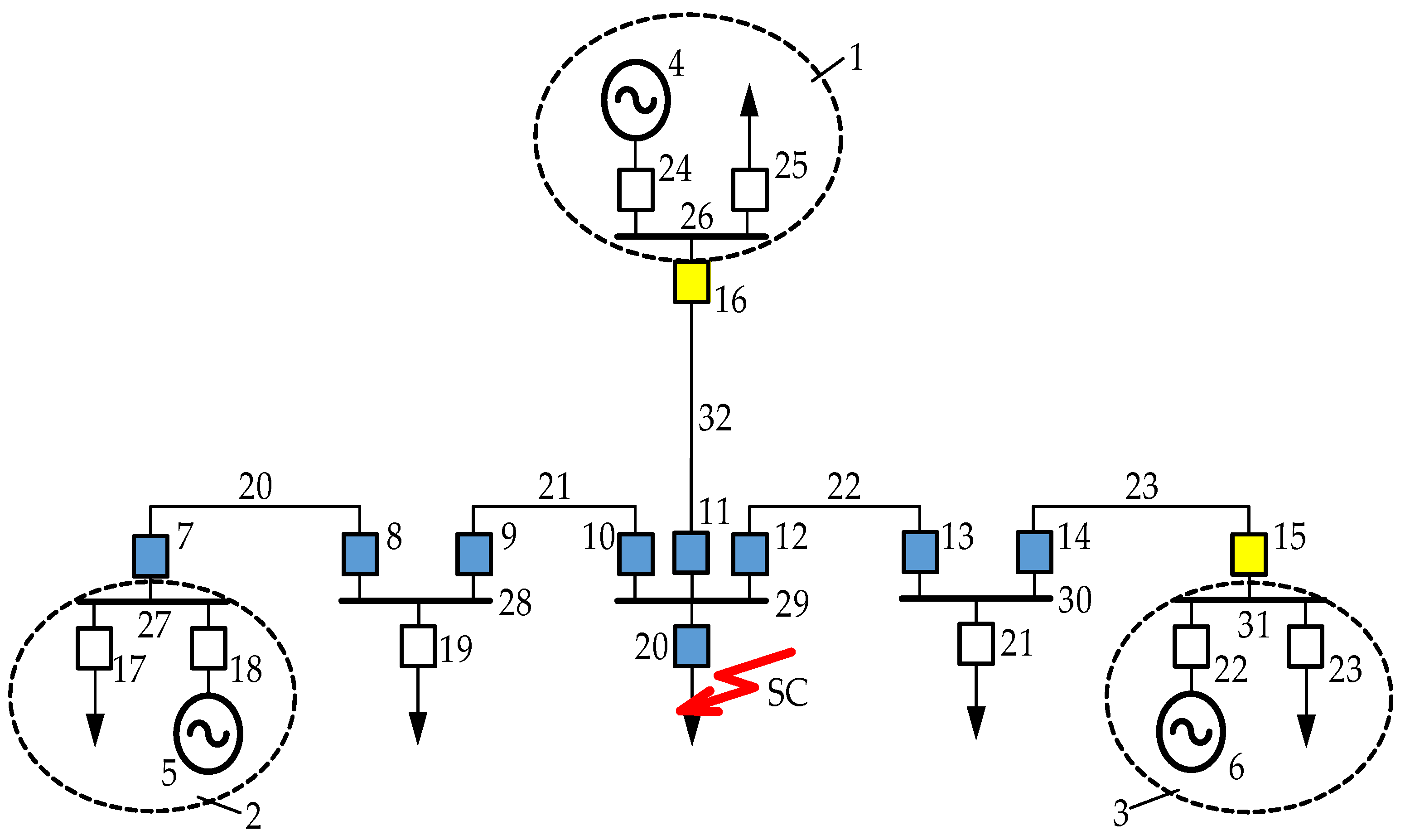
2.2. Managing Emergency-Balanced Network Breakdown

In contrast to the passive network, in which the reliability of power supply is provided by a network reserve, in the active network, with a high degree of power balance, reliability is mainly provided by distributed generation over the network with appropriate management.
An emergency-free breakdown of the active grid into parts is advisable, provided that the parts are sufficiently balanced, which corresponds to the transition to using existing generation to reserve power supply and maintain the operation of power plants. Such disintegration is also provided by appropriate decentralized management [28,29,30], and the subsequent restoration of network integrity and normal operation is associated with solving the problem of synchronization of divided parts [31,32,33,34].

Method of Emergency Management of Network Breakdown into Balanced Energy Districts

The method aims to:
  • Limit short circuit supply currents;
  • Prevent violations of the stability of parallel operation with the occurrence of asynchronous modes;
  • Eliminate impact moments on the shafts of synchronous machines;
  • Eliminate the need to coordinate the protection of the automation of the external network and objects with low generation.
The idea of the method is an advanced balanced separation of a power-balanced power district of the network along one of the a priori fixed cross-sections of the network in the event of disturbances dangerous for violations of the stability of parallel operation, with the transition to the island mode of operation of the power district and subsequent automatic restoration of synchronism and normal mode with the required equipment load. At the same time, initially, the energy district can operate synchronously with the electric grid in one of three modes (be redundant, balanced, or deficient):
(1)
With the output of significant power to the external network along the cross-section (Pout = Pset).
(2)
Without issuing significant power to the external network (Pout = 0).
(3)
With significant power consumption from the external network (Pout = −Pset).
Depending on the mode, one of the two sections is used for emergency separation in case of violations of the normal mode (Figure 1).
Examples of energy district schemes with two sections for separation, associated with the use of this method, are shown in Figure 1, where the energy district has an electrical connection with a substation (SS) of the external electrical network through a distribution point (DP) (Figure 1a), or directly from the generator switchgear (Figure 1b,c).
Section S1 is used for separation from the network in modes of excess generating capacity in Microgrid, section S2 in modes of deficiency of generating capacity.

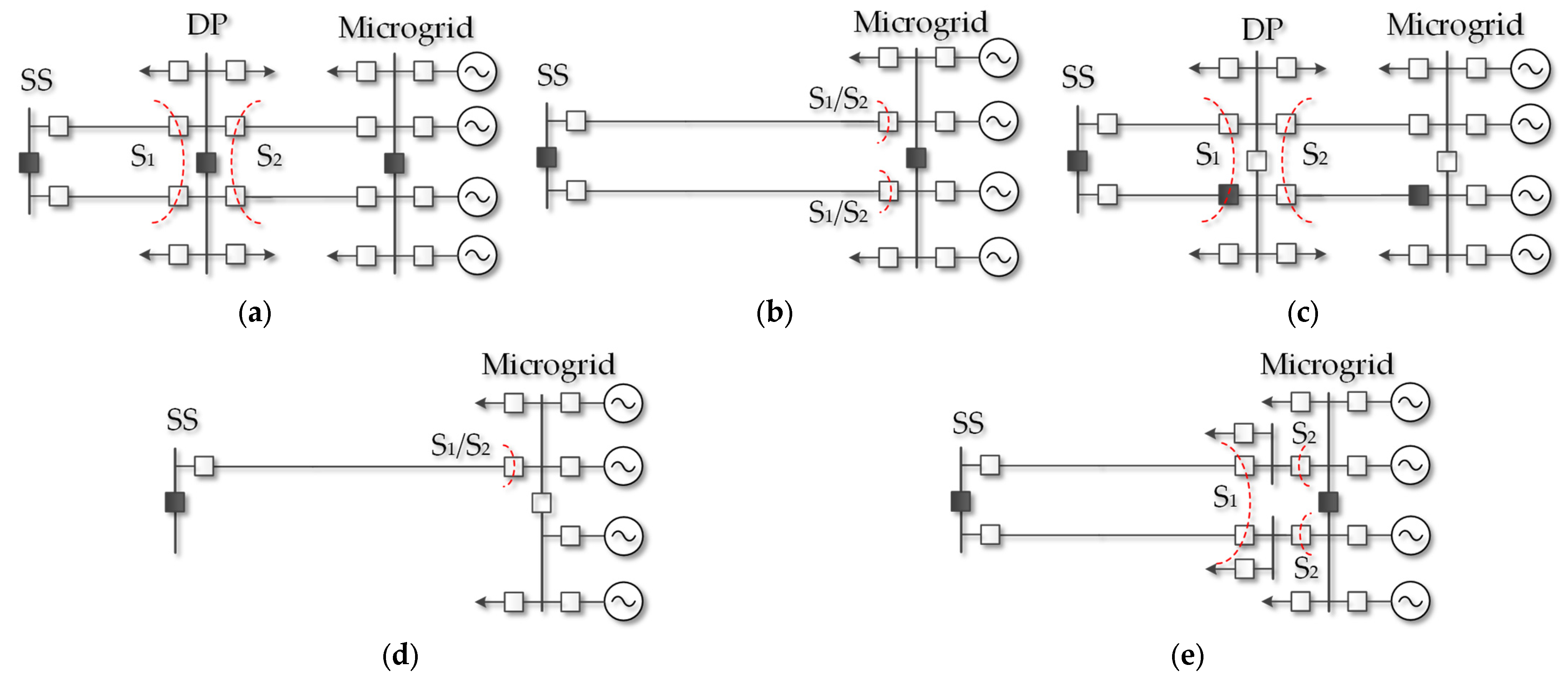
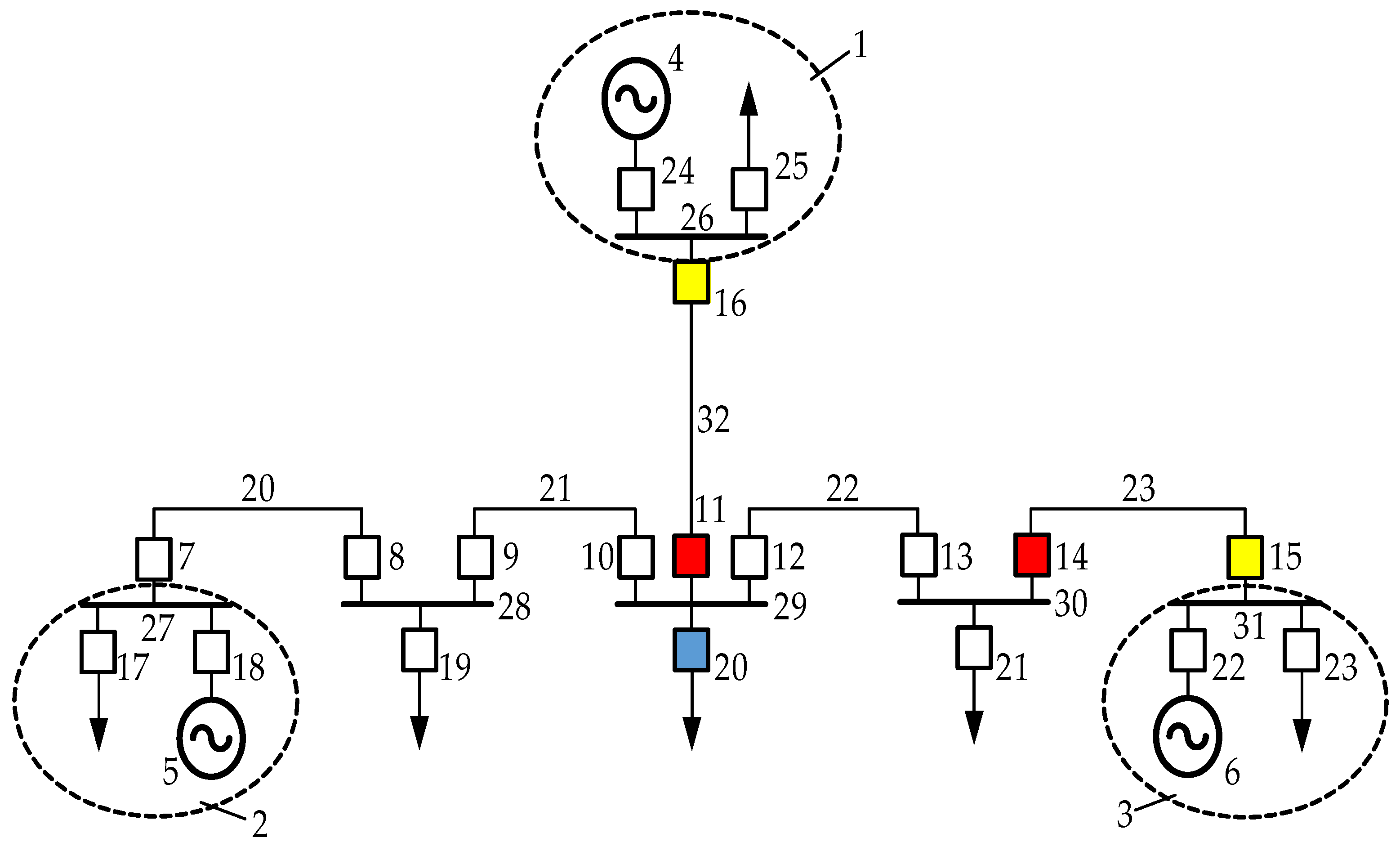
2.3. Decentralized Management of the Restoration of the Integrity and Normal Operation of the Distributed Power Grid after Its Emergency or Emergency Breakdown into Balanced Parts

To restore the integrity of the network with decentralized management, it is necessary to exclude the possibility of simultaneous switching on of switches with the presence of one-way voltage, leading to the unification of parts of the network without synchronization. For this purpose, switches of the electric network with automatic decentralized switching control divide the time of their operation as part of synchronized time cycles, within which each switch is assigned its own time quantum for operation; disconnected switches are turned on when a normal voltage occurs on one side exclusively in their own time quantum, and when a normal voltage occurs on both sides, switches are turned on immediately when all the synchronization conditions for the sources linked by the switch are met. Synchronization by the generator controllers is recorded by the occurrence of current fluctuations with the frequency of the electromechanical transient process.
Restoring network integrity can be divided into two steps:
  • In the first stage, a decentralized assembly of network elements is performed that does not require synchronization of the parts of the network that they combine.
  • The second stage provides decentralized synchronization of separated parts of the network on remote network switches.
Many studies have been devoted to the problem of synchronization of microgrids and separated active parts of the network [35,36,37,38,39,40,41,42,43,44,45,46].
The main factors that determine the features of synchronization of low-power power plants, active parts of the network, and objects with low generation between themselves and the external power system are their low inertia (about 1 s) and high load stochasticity, which determine an order of magnitude more intense fluctuations in frequency and mutual angles during synchronization, as well as the need for synchronization at remote power plants’ network elements in the absence of TV transmission of data about mode parameters.
Existing methods, in particular, the method of passive and active synchronization, do not meet the requirements and conditions of the task. In addition, in active networks, after their collapse, there may be cases of frequency and voltage hovering at an increased or reduced level in certain parts.
To achieve successful synchronization of low-power power plants, active parts of the grid, and objects with low generation, a method for remote synchronization and restoration of the normal mode of an emergency divided electric network is proposed [47]. The purpose of the method is to automatically synchronize and restore the normal mode of parallel operation of separated parts of the electrical network on remote switching devices without using data transmission and remote control commands.
To achieve the success of decentralized synchronization, a special synchronizing control of the power and excitation of generators is proposed, depending on the class of active and reactive power balances in the divided parts of the network.
The process of managing the decentralized synchronization of network parts is divided into several stages:
  • Identification of a quasi-established post-emergency mode in each active part of the network;
  • Identification of the class of active and reactive power balances in separated parts of the network;
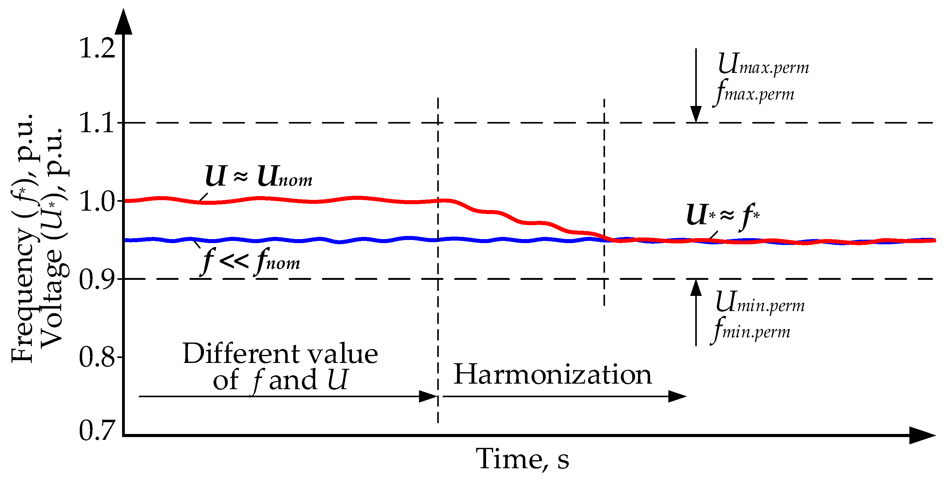
  • Frequency and voltage harmonization in separated parts of the network;
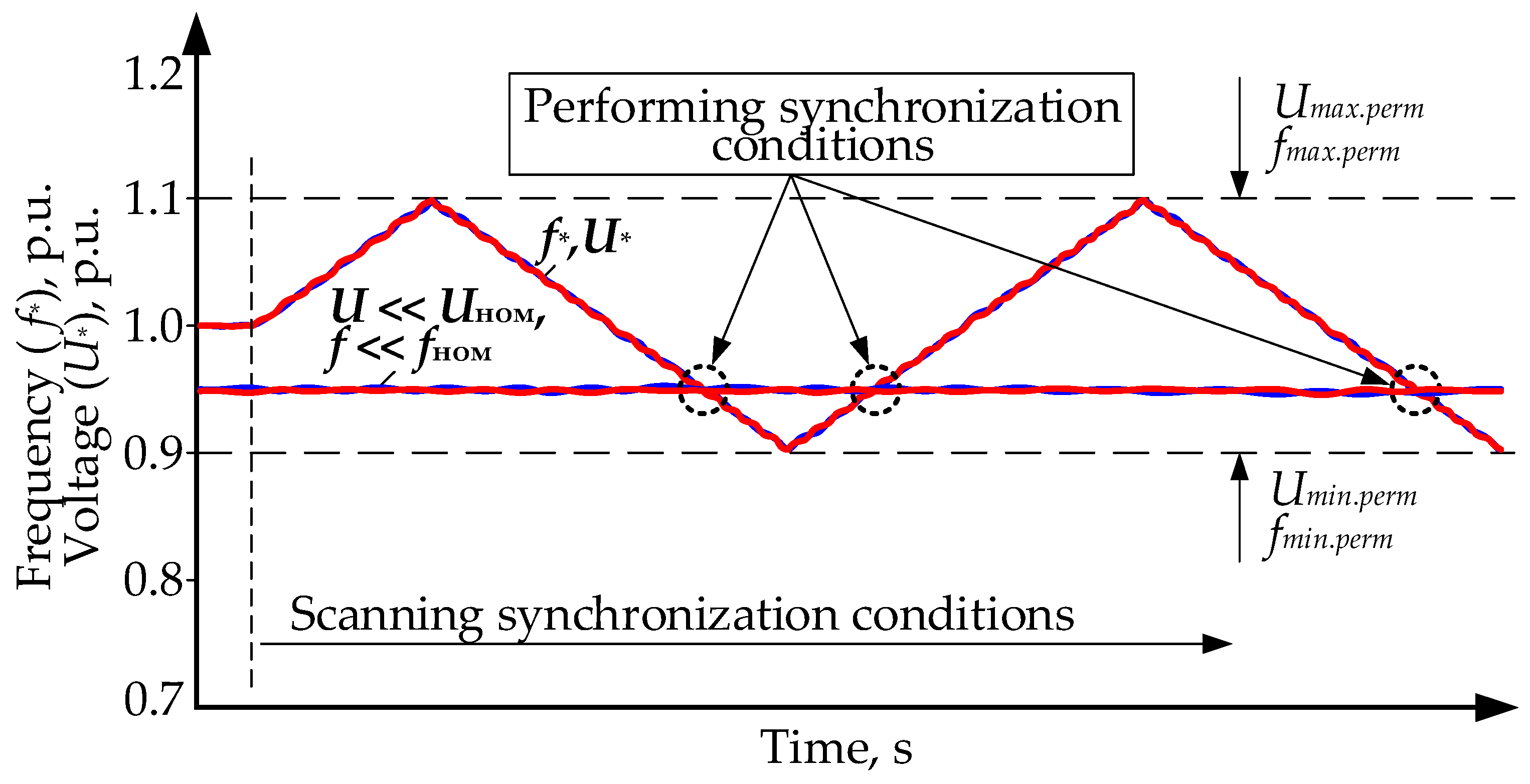
  • Scanning of synchronization conditions in parts of the grid with active and reactive power balances, as well as in separated power plants by low-frequency coordinated (harmonized) frequency and voltage regulation;
  • Enabling network switching devices that detect whether synchronization conditions are met;
  • Identification of signs of its occurrence at power plants that are switched on for parallel operation, with the termination of scanning synchronization conditions and the transition to normal voltage and frequency regulation.

2.3.1. Classes of Active and Reactive Power Balances in Split Parts of the Network

The set of state classes (Table 1) is determined by the consequences of unbalancing the active and reactive power of emergency or emergency-separated parts of the network. The main reason for the inability to restore the normal balance of active and reactive power in the separated part of the network is the exhaustion of reserve active and reactive power as a result of the action of automatic frequency and voltage regulators.
Classes K2–K9 are characterized by the existence of such power unbalances that it is impossible to restore the mode with parameters close to the nominal ones. Class K10 refers to the passive part of the network where consumers completely lose power supply. The K1 class includes those parts of the decayed network that manage to restore the balance of active and reactive power.

2.3.2. Frequency and Voltage Harmonization

Harmonization refers to the operation of the excitation and power regulators aimed at reducing the relative deviations of voltage and frequency from the nominal values to the same value in order to ensure their subsequent consistent change or ensure equality and constancy in relative values (Figure 2).
The purpose of harmonization is to reduce the number of parameters, the coincidence of which is a condition for the operation of switching devices with synchronization detection, because after harmonization, instead of two parameters that differ significantly in relative values, we have a pair with equal or close values.

2.3.3. Scanning Synchronization Conditions

The purpose of scanning is to perform secondary coordinated low-frequency regulation of the harmonized frequency and voltage within the permissible ranges of their change in order to create conditions for successful synchronization of network parts on remote network switching devices.
Figure 3 shows an example of a low-frequency consistent change in frequency and voltage (f, U) in the active part of a class K1 network and a harmonized part of the network with reduced parameters (f << fnom, U << Unom), corresponding to class K9.

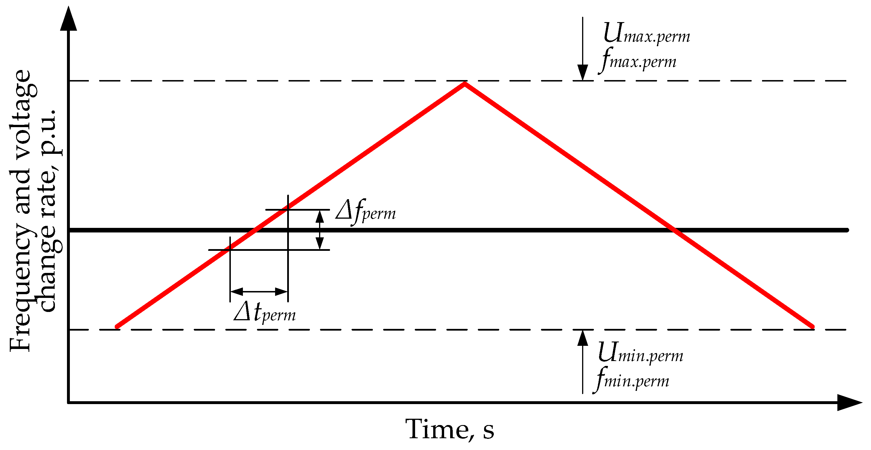
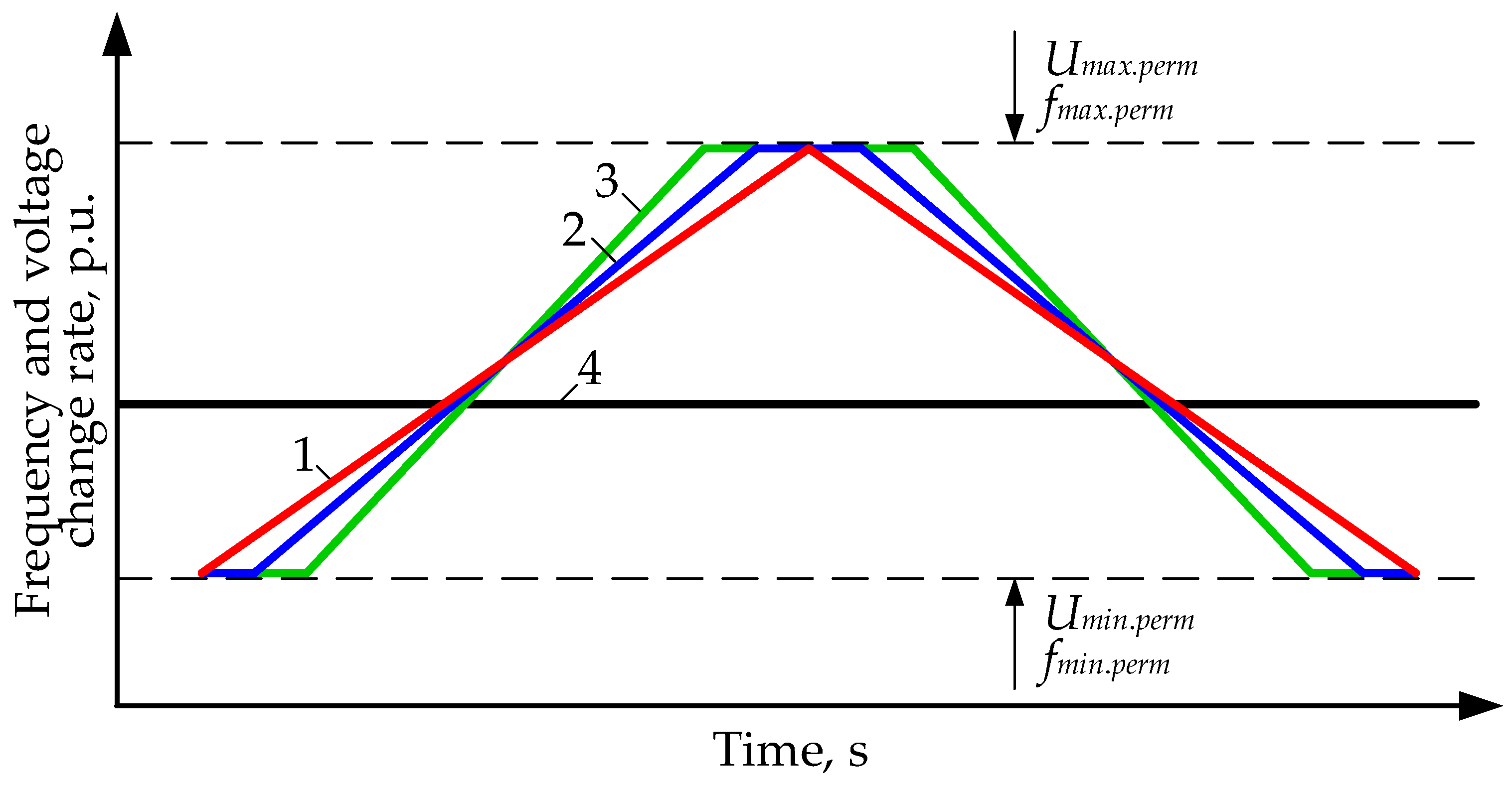
2.3.4. Critical Parameters of the Synchronization Condition Scanning Process

The success of synchronization depends in a decisive way on the parameters of the scanning process and its conditions, which should include:
  • Consistent frequency and voltage range;
  • Form of periodic frequency and voltage changes during scanning;
  • Frequency (period) of frequency and voltage changes during scanning;
  • Phase shift of changes when simultaneously scanning generators in different separated parts of the network.
Let us look at each of these parameters in more detail.
The range of consistent frequency and voltage variations is determined by their maximum possible steady-state deviations in post-accident conditions. For parts of isolated low-power power systems or active networks, you can focus on deviations of ±3–4%.
The form of periodic change is preferably linear, since the intersections of linear functions will always occur at a constant angle, i.e., a constant change in the mutual sliding of the synchronized vectors, regardless of the place of their intersection (values of the coinciding parameters).
The frequency (period) of frequency and voltage changes during scanning is determined by the condition that the mutual angle of the synchronized stress vectors must pass through 0 in the interval of sliding change ± Sperm (for example, ±0.1 Hz/s), which means that the angle is rotated by 360 degrees when the slide changes in the specified range.
These conditions can be graphically represented as follows (Figure 4).
Steepness of the scanning characteristic (SCh):
K = Δ f Δ t ,
Conditions for determining the critical (maximum) mutual steepness of intersecting SCh (Figure 4)
K p e r m = Δ f p e r m Δ t p e r m ; Δ δ r e q = 360 ° ,
where K p e r m = K 1 K 2 —reciprocal slope intersecting SCh; Δ δ r e q —the mutual rotation angle 360 degree on the interval change Δ f = Δ f p e r m to guarantee compliance of the 3rd trigger condition (equal angles).
Determine Δ t p e r m along the track:
Δ δ r e q = 0 Δ t p e r m Δ ω t d t = 360 0 Δ t p e r m Δ f t d t = 360 0 Δ t p e r m K t d t = 60 K t 2 2 | 0 Δ t p e r m = 360 ° .
We obtain Δ t r e q from Equation (3), taking into account Equation (1):
360 = 360 Δ f p e r m Δ t p e r m · Δ t p e r m 2 2 = 180 · Δ f p e r m · Δ t p e r m ,
Then
Δ t r e q = Δ t p e r m = 360 180 · Δ f p e r m .
We obtain for Δ f p e r m = 0.2   Hz   ± 0.1   Hz
Δ t p e r m = 360 180 · 0.2 = 10   s ; K p e r m = Δ f p e r m Δ t p e r m = 0.2 · 360 10 = 7.2   ° / s ,
that is, the critical duration of finding a slip in the permissible zone of 0.2   Hz   ± 0.1   Hz is 10 s. In this case, the angle is rotated 360 degrees.
The duration of passing the frequency of the entire scanning range (for example, 2 Hz) will be 100 s.
The full scan period will be 200 s, i.e., the scan frequency for guaranteed fulfillment of all synchronization conditions will be 0.02 Hz.
Figure 5 shows the SCh for 4 parts of the network, and in order to guarantee the creation of synchronization conditions for all parts of the network in the first half-period (points of intersection of the SCh), it is necessary to create phase displacements of the SCh, i.e., in the general case, the SCh must have the shape of a trapezoid.
It should be noted that scanning f, U during synchronization in balanced parts of the network will necessarily create synchronization conditions for any parts of the network with the power balance classes presented in Table 1 when crossing SCh. As a result, the starting elements of the automatic re-activation device with synchronization detection, including the switching device connecting these parts of the network, are triggered.
The complete process of restoring the integrity and normal operation of the broken-up electrical network can be presented as follows:
  • The network is built in a decentralized manner up to cross-sections that require synchronization;
  • Synchronization of emergency-separated active parts of the electric network is carried out in a decentralized manner using switching devices of parts of the electric network in conditions for creating consistent periodic low-frequency changes in voltage and frequency with a different frequency for each separated part;
  • Switching on parallel operation of parts of the network is recorded, switching from regulating the frequency and voltage on generators to regulating the flow over the cross-section connecting previously separated parts, or to regulating the frequency and voltage in the combined network;
  • The excitation and power regulators of the generator of lower priority in the group of generators scanning synchronization conditions are switched to the mode of maintaining constant active and reactive power until the specified time for restoring the integrity of the electrical network expires;
  • After the specified time for restoring the integrity of the electrical network on the regulators of all generators, the normal mode of frequency and power regulation in the electrical network with many distributed generators is restored.
Figure 6 shows an example of an electrical network diagram (with blue highlighting of disconnected circuit breakers after a short circuit (SC) occurs on the load feeder behind the switch) in which, after its emergency separation, remote synchronization of the emergency-separated parts of the network is performed and the normal mode of their parallel operation is restored.
Figure 7 shows the switching state of the network circuit after successive actuation of network switches with normal voltage on one side of the switch in the process of restoring normal mode within the synchronized time cycle (according to the distribution of time quanta of their operation in the time cycle shown in Figure 8).
The electrical network diagram (Figure 6) contains: 1, 2, and 3—areas of the electrical network with generation; 4, 5, and 6—generators controlled by controllers, with switches 18, 22, and 24 connected to buses 26, 27, and 31; 17, 19, 20, 21, 23, and 25—bus-connected load feeder switches 26, 27, 28, 29, 30, and 31; 7, 8, 9, 10, 11, 12, 13, 14, 15, and 16—network switches with synchronization traps connected to buses 26, 27, 28, 29, 30, and 31; 20, 21, 22, 23, and 32—power transmission lines that connect buses of electric network objects via switches 26, 27, 28, 29, 30, and 31. The switching state of the switches corresponds to the post-emergency mode with the network divided into three active parts (1, 2, and 3) and two passive ones (buses 28 and 29) after switching off the SC on the load feeder behind the switch (20). Yellow color indicates the switches that have kept the on state, and blue—those that have been turned off after a voltage drop as a result of an SC.
Figure 7 shows in white the circuit breakers switched on in the sequential process of restoring the integrity of the network with one-way normal voltage before switching on. Red—switches with broken connections between active parts of the network, where switching on is possible only with synchronization detection.
On all diagrams, network switches are marked with 7, 8, 9, 10, 11, 12, 13, 14, 15, and 16.
The green color indicates switches that did not turn on in the first synchronized clock cycle, because in the given distribution of their time quanta, a one-way voltage did not appear on these switches in the first synchronized clock cycle.
Network integrity is restored as follows:
In the initial normal mode, all circuit breakers (Figure 6) are turned on. Generators 4, 5, and 6 operate in parallel in a shared network. All generators are involved in primary frequency control. The first generator performs secondary frequency control.
If an emergency disturbance occurs (SC behind switch 20), a group of switches is switched off by high-speed protection when the voltage drops below the setpoint (8, 9, 10, 11, 12, and 6). The network is divided into three active parts (1, 2, and 3) and two passive parts (bus 28 and 29). Generator controllers (4, 5, and 6), upon voltage reduction, start coordinated low-frequency (frequencies for generators are individual, for example, 0.03, 0.02, and 0.01 Hz) control of frequency and voltage within the permissible ranges of their change (description of this generation control method to ensure that synchronization conditions are met at remote sites switches are listed below). Also, after the voltage is reduced, the controllers of network switches are allowed to turn on in synchronized time cycles at intervals of their own time slice.
In the first clock cycle of time, one-way voltage switches are switched on sequentially: 8th, 9th, and 10th. On the switch 11, catching the fulfillment of synchronization conditions is started, since the voltage appears on both sides of the disconnected switch, then the 12th one is turned on, followed by the 13th one. At switch 14, synchronization conditions are detected, since voltage appears on both sides of the disconnected switch. After the voltage appears on bus 29 of the 20th switch, its automatic reclosing (AR) is triggered, but, due to the non-eliminated short circuit, the switch turns off with acceleration, while maintaining the on state of the other network switches.
Further, as a result of coordinated low-frequency regulation of the frequency and voltage within the permissible ranges of their change, synchronization conditions are met on generators 4, 5, and 6, for example, on switch 11. It is switched on, which leads to the occurrence of parallel operation of generators 4 and 5 and the manifestation of a damped transient electromechanical process in the generator currents. Upon the occurrence of the frequency of the electromechanical process in the current, the generator controllers 4 and 5 stop the coordinated low-frequency regulation of frequency and voltage within the permissible ranges of their change and transfer the excitation and power regulators to the state of regulation of the normal network mode.
Further, as a result of the coordinated low-frequency regulation of the frequency and voltage within the permissible ranges of their changes on the generator 6, the synchronization conditions on the switch 14 are met. It is turned on, which leads to the occurrence of parallel operation of generators 4, 5, 6 and a damped transient electromechanical process in the generator current 6. Upon the occurrence of the frequency of the electromechanical process in the current, the generator controller 6 stops the coordinated low-frequency frequency control and voltage within the permissible ranges of their change and switches the excitation regulators and power to the state of regulation of the normal mode of the network.
In this example, all network switches with one-way normal voltage were triggered in one synchronized time cycle. When using, for example, vacuum circuit breakers with a trip and turn-on response time (taking into account the automatic response time) of 0.06 s, the time quantum with a time margin of; for example, 0.04 s is 0.06 + 0.06 + 0.04 = 0.16 s, and the duration of the synchronized time cycle, taking into account all network switches, will be 10 × 0.16 = 1.6 c. The maximum synchronization time can be estimated as half of the longest scan period for synchronization conditions. In the example, ½ × 1/0.01 = 50 s.
The total maximum time to restore network integrity and normal operation is 50 + 0.16 = 50.16 s, i.e., about one minute.
Thus, the controllers of switching devices of generators, network switches do not interact with each other, but together perform automatic decentralized synchronization of generating devices and restore the integrity and normal operation of the electrical network when it is initially divided into many electrically isolated parts with generators and when multiple switches are disconnected in the electrical network on the links between the separated active parts of the network. A necessary condition for successful restoration of network integrity is effective synchronization of the separated parts.

3. Research Tools and Methods

The research methodology consists of developing specialized methods for controlling the modes of electric networks with a distributed small generation, multi-agent control system that uses these methods to implement decentralized management, and modeling the modes of electric networks with multi-agent management to study their features and effectiveness.
Modeling and research of electrical network modes was carried out using RastrWin 3 (version 2.6.0.6220), Matlab Simulink (version 2020a) software and computing complexes, a physical complex, as well as in the process of pilot operation of the automation system of a local intelligent power system that provides power to residential areas.
Experimental confirmation of the efficiency of the decentralized control technology was carried out on the basis of the electrodynamic model (EDM) of the center for collective use ‘Center for Testing devices for Monitoring and Controlling the Modes of Electric Power Systems’ at Novosibirsk State Technical University.
The microgrid model is a set of special equipment that simulates the operation of the main elements of the original.
With the exception of primary engines (gas-piston engines and turbines) and overhead power lines, all other elements of the microgrid and external electrical network are represented on the EDM by large-scale physical models. The parameters and design of the power elements of the model are selected in such a way as to meet the similarity criteria as much as possible when modeling, first of all, transient electromechanical processes.
The microgrid model includes power and switching equipment, measuring and recording devices and apparatuses, as well as a control system (a prototype of the developed multi-agent control automation).
The object model consists of three main groups of equipment:
  • Power and switching equipment;
  • Measuring and recording devices and apparatuses;
  • Control system.
Model synchronous machines (with a primary DC drive motor) of the MT-5-1500 and MK-3-1500 types were used as generating units (GUs). The parameters of the model generators (Figure 9) are shown in Table 2.
Models of power lines, switches, and loads with power from 450 W to 2000 W were also used.
To test prototypes of automation devices for decentralized emergency management of network breakdown into parts with subsequent restoration of normal operation, circuit-mode and emergency situations were created on the physical model, similar to those in which the tested equipment should operate in real operating conditions.
For this purpose, an electrical network was modeled with three low-power microgrids, represented by three generators operating both at local load and in parallel to each other (Figure 9). A prerequisite is the connection of the GUs to each other through communication lines simulating their ‘remoteness’, the ability to control 3 generator switches and 4 network switches (Q1–Q4).
The scheme shown in Figure 10 was used as a general scheme for research and development of the entire complex of automation systems for decentralized control of network modes.
The presented scheme has a high multivariance of network switching structures, normal and emergency modes, and allows us to study the effectiveness of various control technologies, and check the operability of algorithms and devices for mode and emergency control.
The functional unit of the emergency automation complex multifunctional was used as a control unit for multi-agent control [48]. This complex is designed to perform the functions of emergency response devices, process automation, relay protection, and system automation installed at electric power facilities.

4. Results and Discussion

4.1. Processes in Case of Emergency-Balanced Breakdown of the Electric Grid

Managing the emergency breakdown of an active network into functional parts is an alternative to the concept of ensuring the reliability of the power system through maintaining its integrity, provided that the network is balanced with distributed small generation. A special case of such decay is the emergency separation of the active area of the network (or microgrid) from the external power system when the stability of the parallel operation of sources is unavoidable or dangerous dynamic moments occur on the generator shafts during disturbances (passing SC in the external network) [49,50].
Studies of the processes involved in controlling the emergency-balanced separation of the microgrid from an external network (network breakdown) were carried out in conjunction with the development of appropriate automation for a real object [49].
Figure 11 shows a calculated transient process with a representation of the parameters of one of the five generators of the general group with a three-phase SC running on 110 kV buses of the main supply substation without separating the microgrid from the external electrical network.
From the transition process, you can see a violation of the stability of parallel operation with the rotation of the generator rotor relative to the external network. In real-world conditions, the power units of the power plant in this process would be turned off by defenses with the power plant fully extinguished.
Figure 12 shows a calculated transient process with a representation of the parameters of one of the five generators of the general group with a three-phase SC running on 110 kV buses of the main power substation with express emergency-balanced separation of the microgrid from the external network along one of the pre-prepared cross-sections (shutdown time—0.08 s).
From the obtained waveform, it follows that the maximum frequency increase was 2.8 Hz. Fluctuations and deviations of the operating parameters of the generators stored in operation are permissible and do not lead to their shutdown by the power unit protection systems. Process parameters ensure that the microgrid is able to operate in offline mode after an emergency.

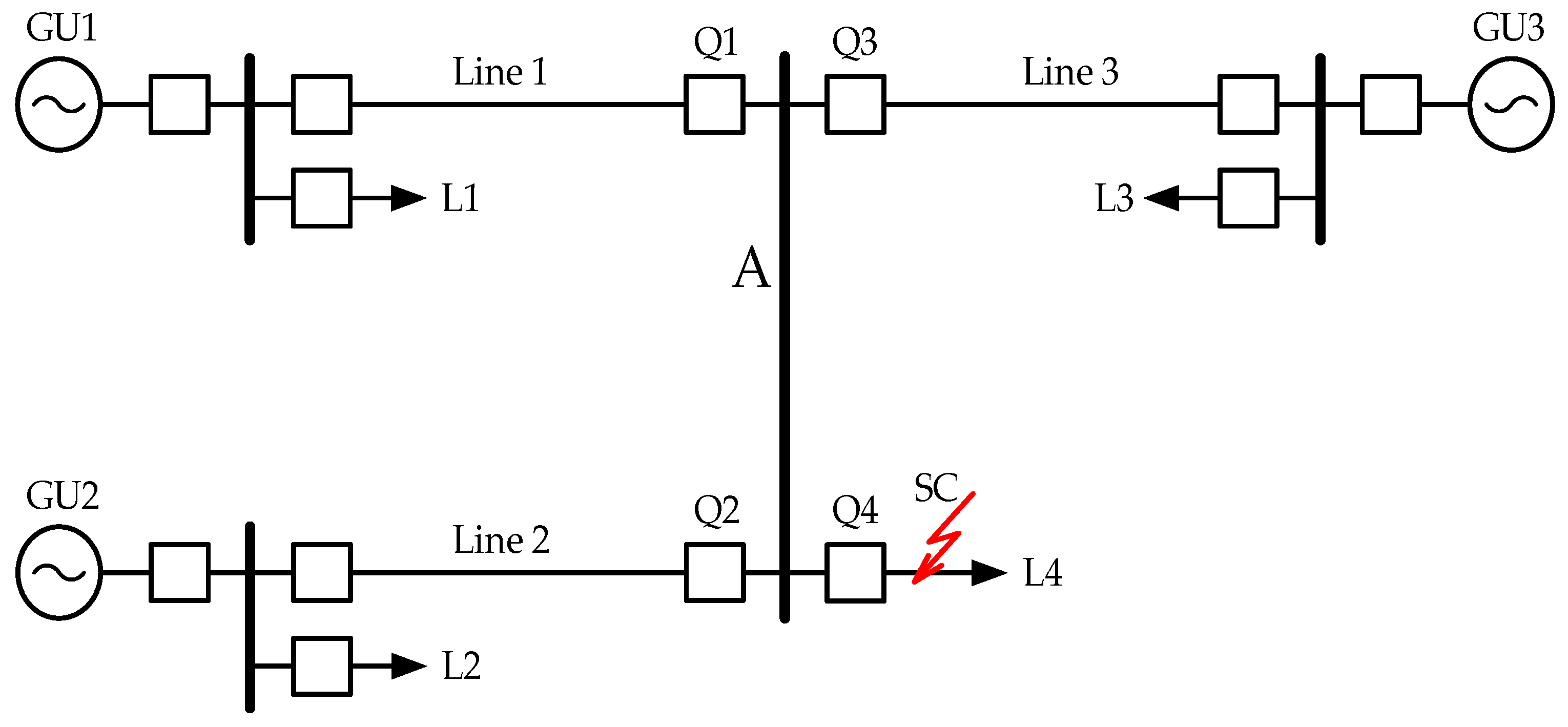
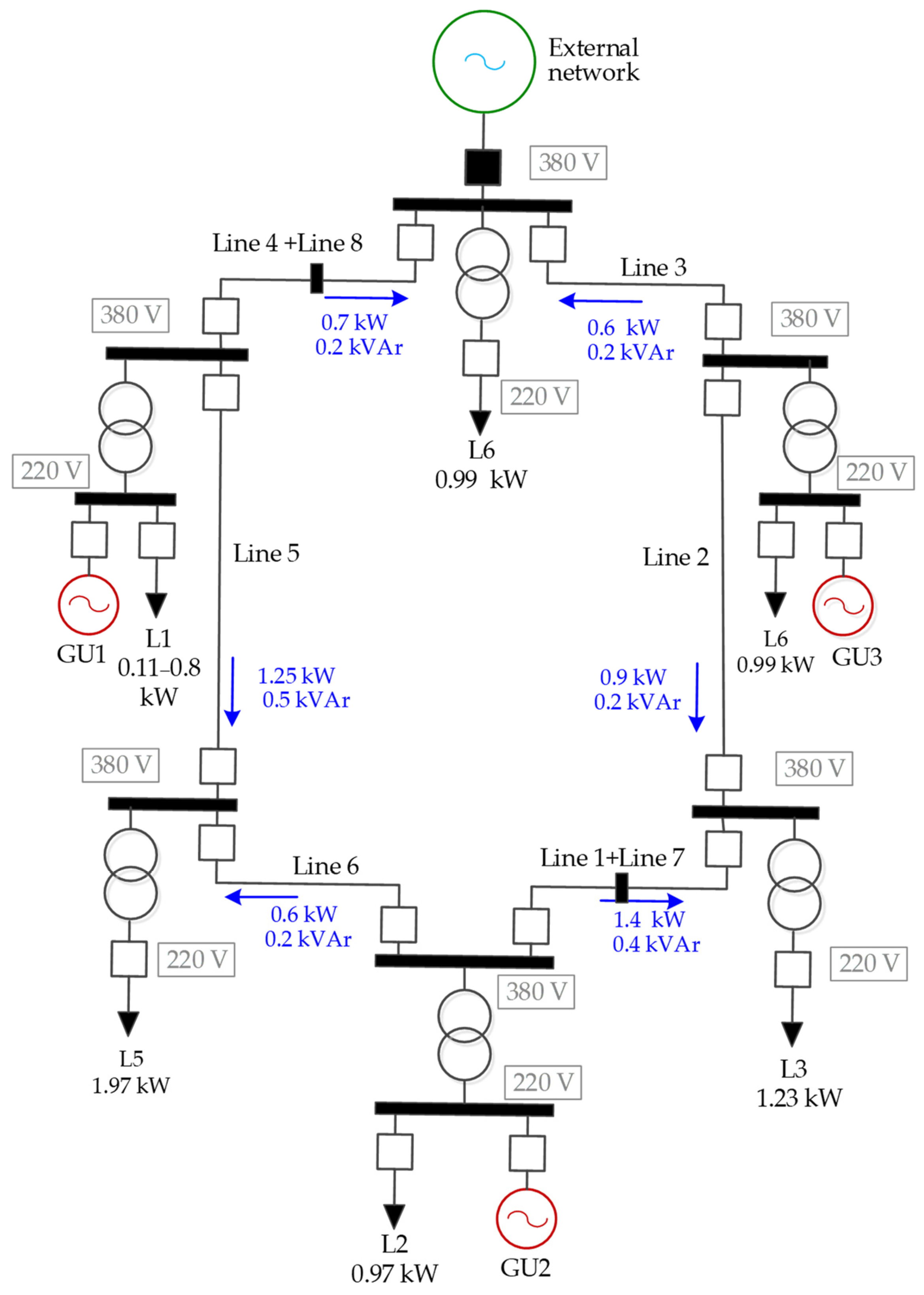
4.2. Experimental Study of Decentralized Emergency Management of the Breakdown into Balanced Parts, Restoration of the Integrity, and Normal Operation of the Electric Network with Distributed Generation on a Physical Model of the Power System

To test prototypes of automation devices for the decentralized emergency management of network breakdown into parts with the subsequent restoration of normal operation, a diagram, Figure 9, was created of the physical model.
During the tests, the following were performed:
  • Starting generators GU1–GU3 by switching on generator switches to power local loads. At this stage, all generators operate independently, and therefore, the controllers of all generators operate in the mode of maintaining the frequency and voltage setpoints on the generator buses.
  • Start-up of the AR with detection of synchronism of switches Q1–Q3. After synchronizing the generators with each other, it is necessary to switch GU2 and GU3 to the cross-section power flow control mode (the original scheme with the normal mode is assembled).
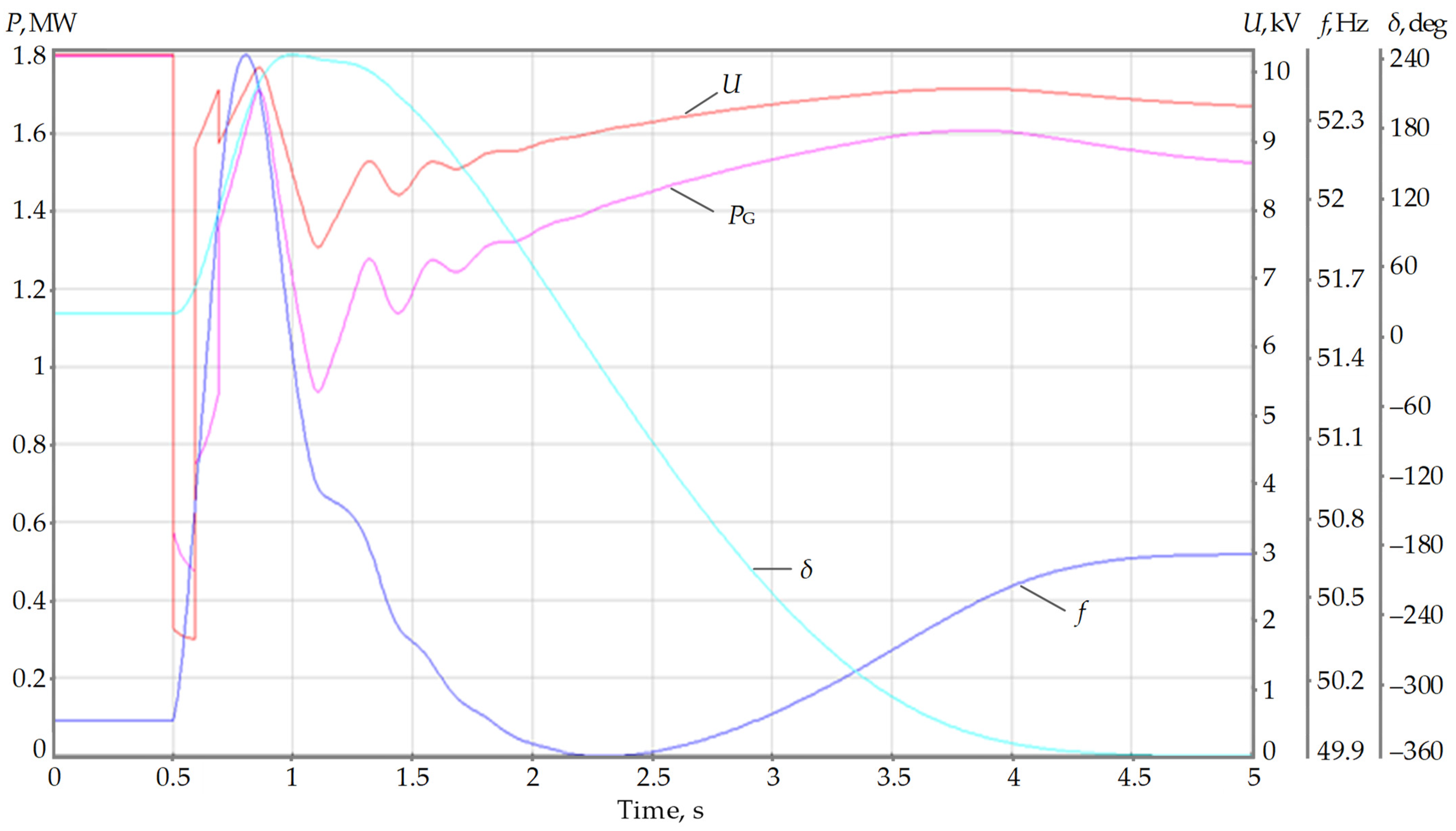
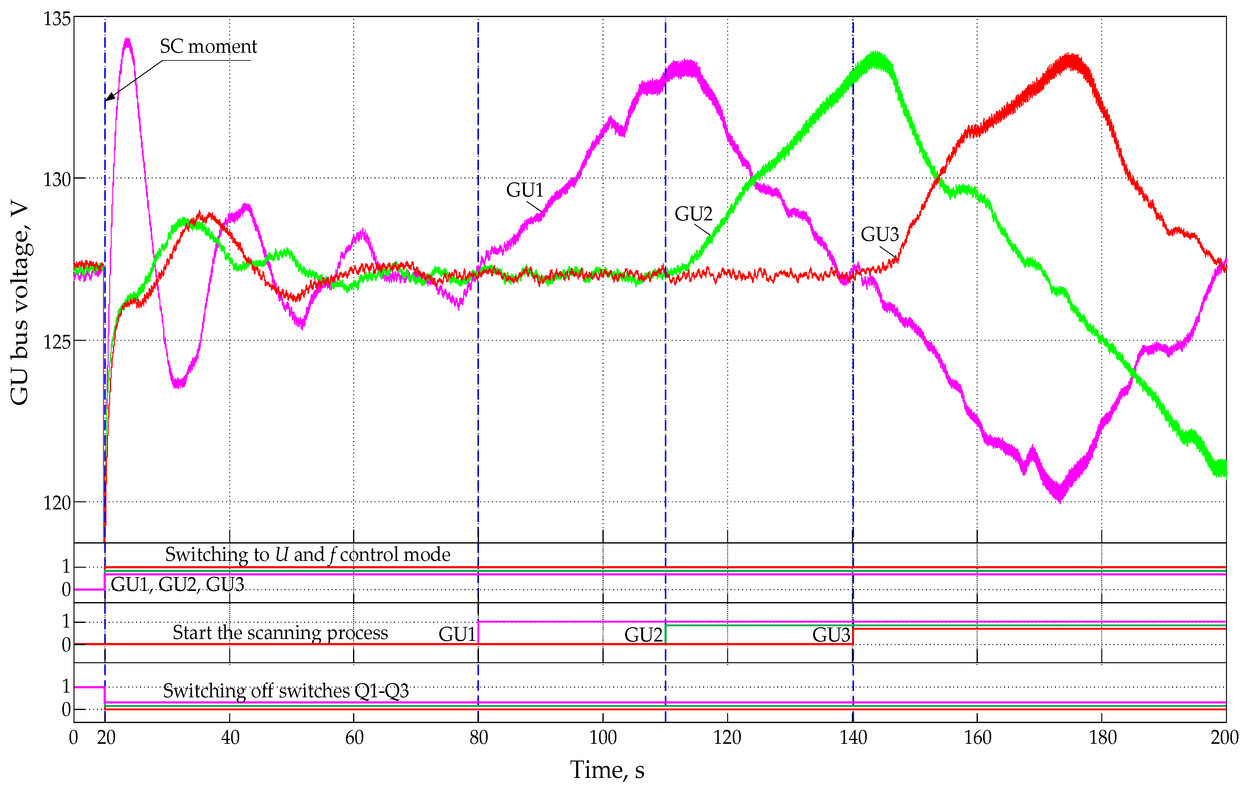
  • Create a three-phase SC mode by manually turning on the Q4 switch to short-circuit. As a result of such a disturbance, the built-in protective functions in the AR devices should turn off switches Q1–Q3, generators GU2 and GU3 should switch to the frequency and voltage control mode, and, after the specified time exposures (60, 90 and 120 s, respectively), the ‘scanning’ process starts (completed successfully, Figure 13).
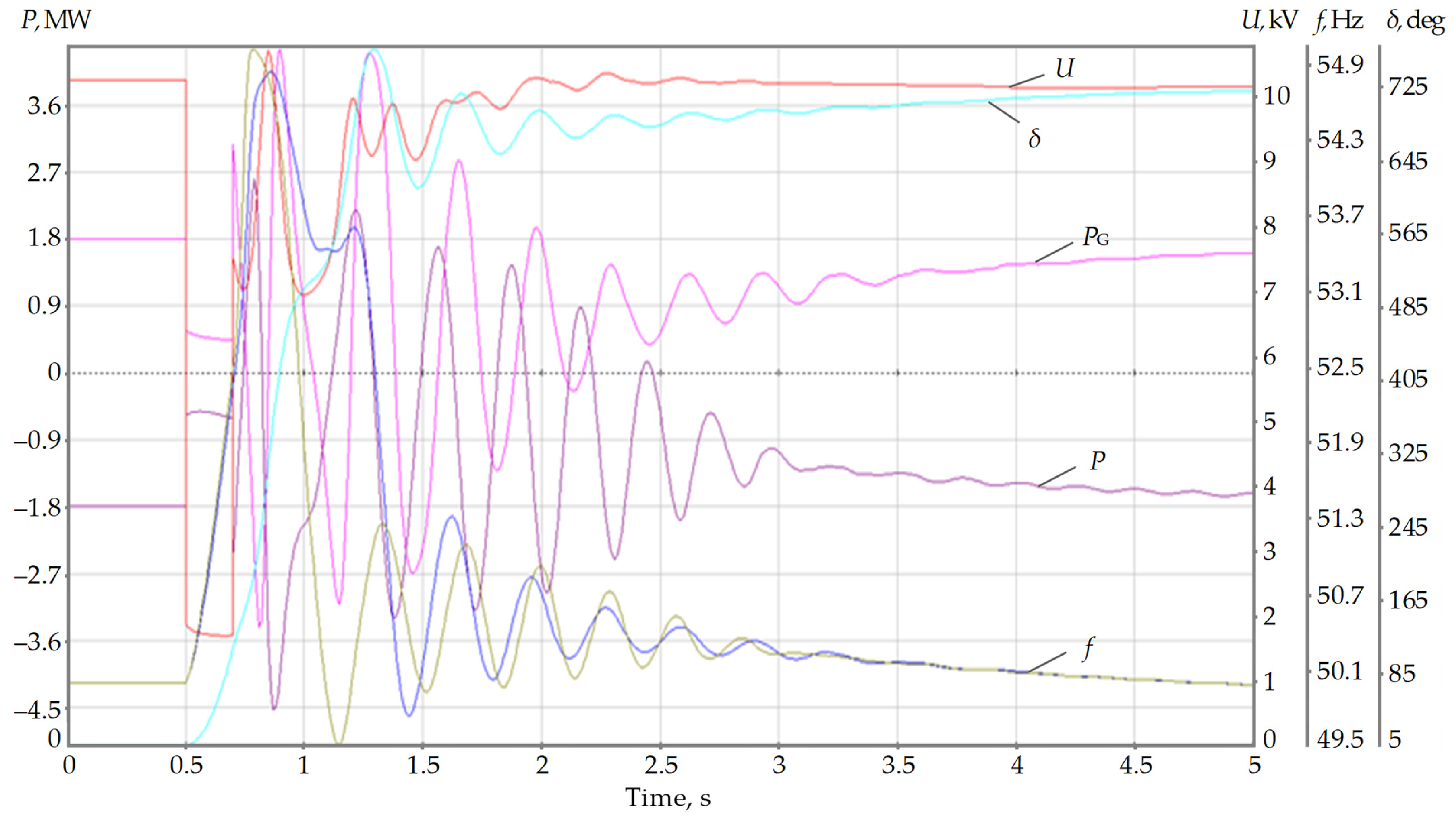
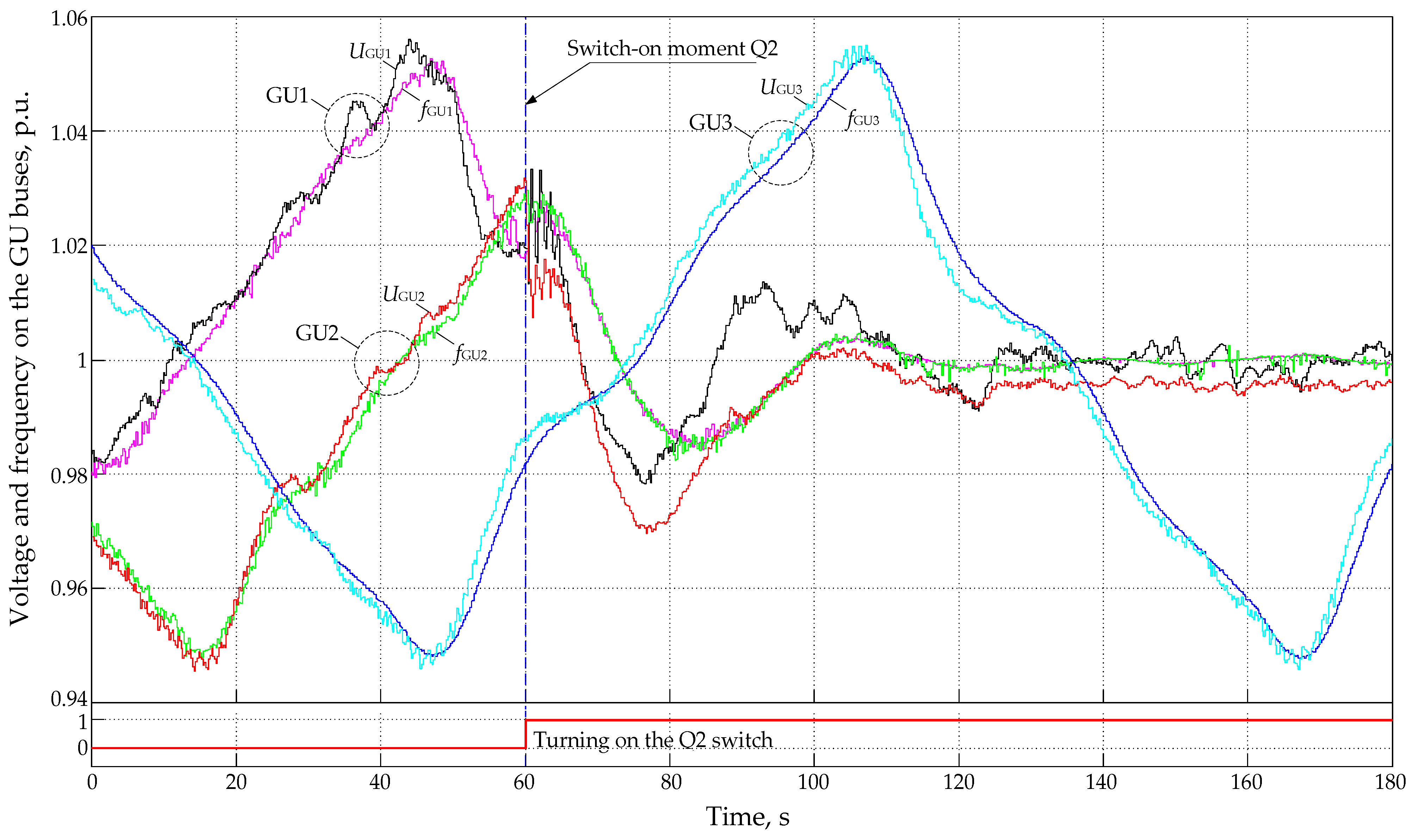
  • After disconnecting the SC, the Q1 switch should turn on, which will cause A voltage to appear on the A-bus (Figure 9). During the scanning process, conditions for synchronization are created on the switch Q2 (for example), and it turns on. Fixing the electromechanical process, GU1 and GU2 must stop the scanning process and switch to the initial control mode: GU1—the mode of secondary frequency and voltage regulation, and GU2—in the mode of issuing a given power or maintaining a given cross-section flow. In this mode, the frequency in the combined network is maintained at 50 Hz. GU3 continues the scanning process (completed successfully, Figure 14).
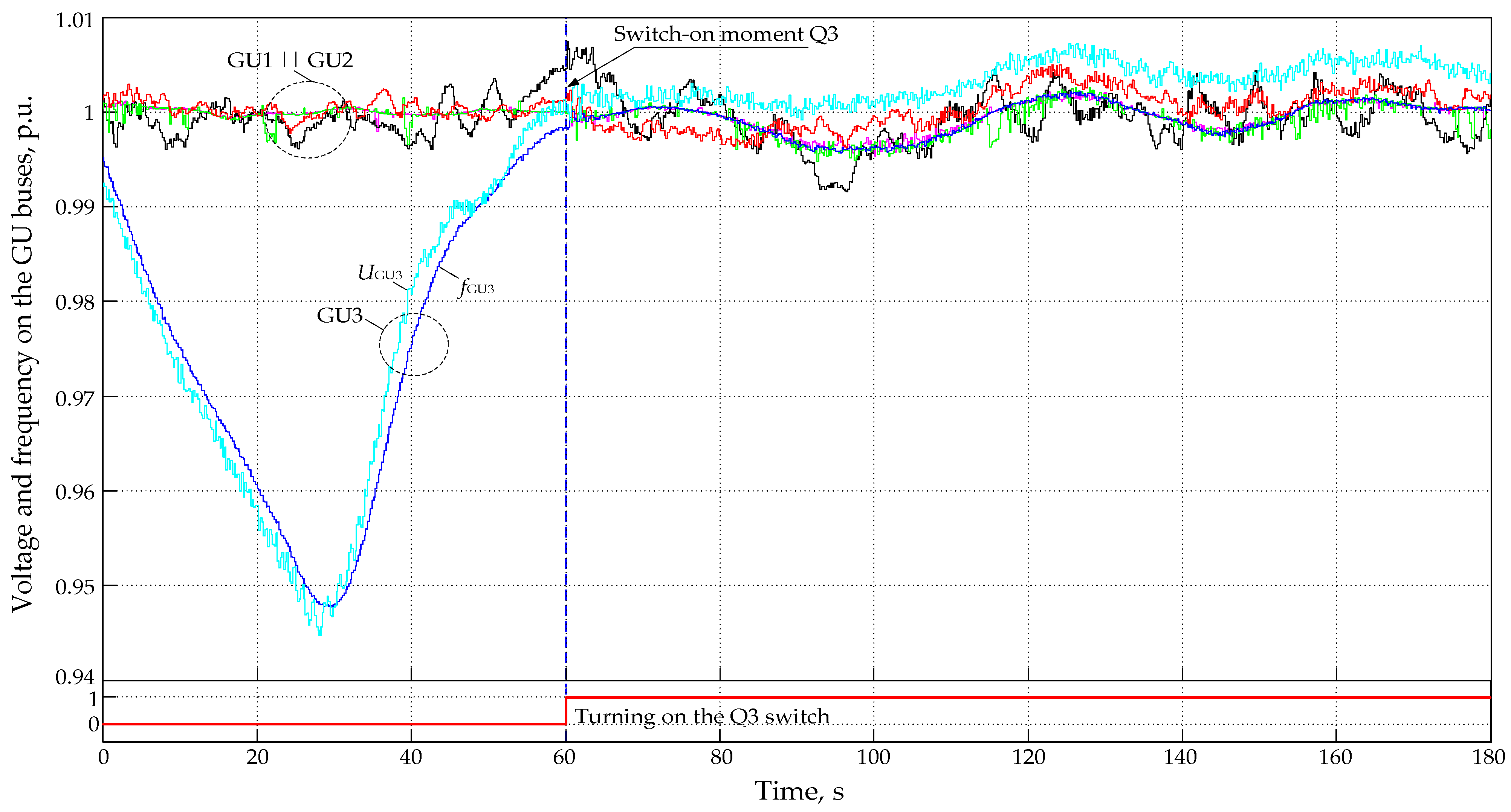
  • Finally, during the scanning process of GU3, synchronization conditions are created on the Q3 switch, and it turns on. Fixing the electromechanical process, GU3 must stop the scanning process and switch to the initial control mode—the mode of maintaining the set power or power flow over the cross section. Automatic restoration of the normal network operation has been completed (completed successfully, Figure 15).
Experimental studies and verification of the operability of methods and algorithms for decentralized emergency management of a network with distributed power generation on a physical model of the power system made it possible to verify and evaluate the main parameters of decentralized management processes.
The duration of the full cycle of emergency separation of the network, restoration of its integrity, and normal operation, is mainly determined by the time of frequency harmonization with voltage, scanning the synchronization conditions of parts of the network and their number. Harmonization of operating parameters is provided within 8–10 s. Scanning of synchronization conditions in the range of ±2.5 Hz (52.5 Hz and 47.5 Hz) has a full period duration of 120 s. The time of automatic recovery of the active electrical network after breaking up into three parts is 200–240 s.
It should be explained that during the time intervals of 75 s and 135 s (Figure 14), the AR of the Q3 switch did not work and did not turn on the GU3 generator for parallel operation with the rest of the network due to the failure of the angle synchronization condition (angle hovering for 6–8 s). Successful activation of the GU3 generator can be seen in the waveform of Figure 15. It should be noted that the success of synchronization was affected by a change in the shape of the intersection of two pairs (frequency and voltage) of mode parameters, i.e., when the shape of the intersection of parameters with a steep slope begins to turn into a gentle shape.
A local sign of switching on the active parts of the network for parallel operation is the occurrence of damped oscillations in the generator currents with the frequency of an electromechanical transient process in the network.
Thus, the results of the conducted experimental studies have confirmed the operability and effectiveness of decentralized emergency management of the modes of electric networks with distributed generation, as well as the automatic restoration of its integrity and normal operation.

5. Conclusions

The development of small-scale generation distributed over the network, and the facilities it is based on, requires the creation of a decentralized system for managing the modes of such a network, including the active and reactive power sources that are part of it. Independent object management systems of such a network, in fact, become agents of some multi-agent systems that perform consistent management of the general mode.
The presented multi-agent emergency management system is part of a comprehensive system for decentralized management of power grid modes with distributed small-generation facilities, which is an expert-type distributed artificial intelligence system with decision-making centers based on general rules.
The results of this study confirmed the effectiveness of the specialized methods proposed by the authors for decentralized emergency management of the power grid modes with distributed generation; in particular: advanced balanced separation of power districts of the network along one of the a priori fixed network sections in the event of disturbances with the transition to island mode; two-stage restoration of the integrity and normal mode of the network with synchronization of active parts on remote network switches. In the case of decentralized remote synchronization of active parts, it is proposed to use special control of the excitation and speed of generators to create conditions for the successful operation of AR devices with synchronization detection.
Studies on the physical model of electric network modes with a distributed emergency automation that does not use data transmission tools have proved the feasibility of decentralized management and its high cybersecurity.

Author Contributions

All authors have made valuable contributions to this paper. Conceptualization, A.F., A.O., A.M. and A.G.; methodology, A.G., A.M. and M.S.; software, A.O. and A.G.; validation, A.F., S.K., S.D. and I.Z.; formal analysis, A.F., A.G., A.M. and A.O.; investigation, A.G., M.S., A.M., A.F., A.O., S.D., I.Z. and S.K.; writing—original draft preparation, A.G., A.F., A.M., A.O. and I.Z.; writing—review and editing, M.S., S.D. and I.Z.; supervision, A.F., S.K. and I.Z. All authors have read and agreed to the published version of the manuscript.

Funding

The research was supported by grants from the Russian Science Foundation № 23-29-10186 and grant № r-56 of the Government of the Novosibirsk Region.

Data Availability Statement

Not applicable.

Conflicts of Interest

The authors declare no conflict of interest.

References

  1. Voropay, N.I.; Keiko, A.V.; Saneev, B.G.; Senderov, S.M.; Stennikov, V.A. Trends in the development of centralized and distributed energy. Energy Econ. Technol. Ecol. 2005, 7, 2–11. (In Russian) [Google Scholar]
  2. Ahlqvist, V.; Holmberg, P.; Tangerås, T. A survey comparing centralized and decentralized electricity markets. Energy Strateg. Rev. 2022, 40, 100812. [Google Scholar] [CrossRef]
  3. McArthur, S.D.J.; Davidson, E.M.; Catterson, V.M.; Dimeas, A.L.; Hatziargyriou, N.D.; Ponci, F.; Funabashi, T. Multi-Agent Systems for Power Engineering Applications—Part I: Concepts, Approaches, and Technical Challenges. IEEE Trans. Power Syst. 2007, 22, 1743–1752. [Google Scholar] [CrossRef] [Green Version]
  4. McArthur, S.D.J.; Davidson, E.M.; Catterson, V.M.; Dimeas, A.L.; Hatziargyriou, N.D.; Ponci, F.; Funabashi, T. Multi-Agent Systems for Power Engineering Applications—Part II: Technologies, Standards, and Tools for Building Multi-agent Systems. IEEE Trans. Power Syst. 2007, 22, 1753–1759. [Google Scholar] [CrossRef] [Green Version]
  5. Altin, N.; Eyimaya, S.E.; Nasiri, A. Multi-Agent-Based Controller for Microgrids: An Overview and Case Study. Energies 2023, 16, 2445. [Google Scholar]
  6. Yao, R.; Hu, Y.; Varga, L. Applications of Agent-Based Methods in Multi-Energy Systems—A Systematic Literature Review. Energies 2023, 16, 2456. [Google Scholar] [CrossRef]
  7. Gomez-Sanz, J.; Garcia-Rodriguez, S.; Cuartero-Soler, N.; Hernandez-Callejo, L. Reviewing Microgrids from a Multi-Agent Systems Perspective. Energies 2014, 7, 3355–3382. [Google Scholar]
  8. Ma, Z.; Schultz, M.J.; Christensen, K.; Værbak, M.; Demazeau, Y.; Jørgensen, B.N. The Application of Ontologies in Multi-Agent Systems in the Energy Sector: A Scoping Review. Energies 2019, 12, 3200. [Google Scholar] [CrossRef] [Green Version]
  9. Dou, C.-X.; Liu, B. Multi-Agent Based Hierarchical Hybrid Control for Smart Microgrid. IEEE Trans. Smart Grid 2013, 4, 771–778. [Google Scholar] [CrossRef]
  10. Dou, C.; Yue, D.; Li, X.; Xue, Y. MAS-Based Management and Control Strategies for Integrated Hybrid Energy System. IEEE Trans. Ind. Inform. 2016, 12, 1332–1349. [Google Scholar] [CrossRef]
  11. Abdulmohsen, A.M.; El-Sharkawy, M.A.; Omran, W.A. Power management in islanded microgrids using multi-agent systems. In Proceedings of the 2016 IEEE PES Innovative Smart Grid Technologies Conference Europe (ISGT-Europe), Ljubljana, Slovenia, 9–12 October 2016. [Google Scholar]
  12. Nguyen, T.-L.; Wang, Y.; Tran, Q.-T.; Caire, R.; Xu, Y.; Besanger, Y. Agent-based Distributed Event-Triggered Secondary Control for Energy Storage System in Islanded Microgrids—Cyber-Physical Validation. In Proceedings of the 2019 IEEE International Conference on Environment and Electrical Engineering and 2019 IEEE Industrial and Commercial Power Systems Europe (EEEIC/I&CPS Europe), Genova, Italy, 11–14 June 2019. [Google Scholar]
  13. He, S.; Zong, X. Multiagent-based Sampled-data Frequency Control of Microgrid with Additive Noise. In Proceedings of the 2020 39th Chinese Control Conference (CCC), Shenyang, China, 27–29 July 2020. [Google Scholar]
  14. Cintuglu, M.H.; Mohammed, O.A. Multiagent-based decentralized operation of microgrids considering data interoperability. In Proceedings of the 2015 IEEE International Conference on Smart Grid Communications (SmartGridComm), Miami, FL, USA, 2–5 November 2015. [Google Scholar]
  15. Kumar Nunna, H.S.V.S.; Doolla, S. Multiagent-Based Distributed-Energy-Resource Management for Intelligent Microgrids. IEEE Trans. Ind. Electron 2013, 60, 1678–1687. [Google Scholar] [CrossRef]
  16. Dimeas, A.L.; Hatziargyriou, N.D. Operation of a Multiagent System for Microgrid Control. IEEE Trans. Power Syst. 2005, 20, 1447–1455. [Google Scholar] [CrossRef]
  17. Eddy, Y.S.F.; Gooi, H.B.; Chen, S.X. Multi-Agent System for Distributed Management of Microgrids. IEEE Trans. Power Syst. 2015, 30, 24–34. [Google Scholar] [CrossRef]
  18. Ren, F.; Zhang, M.; Soetanto, D.; Su, X. Conceptual Design of A Multi-Agent System for Interconnected Power Systems Restoration. IEEE Trans. Power Syst. 2012, 27, 732–740. [Google Scholar] [CrossRef]
  19. Bulatov, Y.N.; Shumansky, E.K. Simulation of a multi-agent network voltage control system with distributed generation units. Proc. Bratsk State Univ. Nat. Eng. Sci. Ser. 2019, 2, 92–95. (In Russian) [Google Scholar]
  20. Bulatov, Y.N.; Shumansky, E.K. Multi-agent voltage regulation system in electric networks with small distributed generation units. Proc. Bratsk State Univ. Nat. Eng. Sci. Ser. 2021, 1, 141–145. (In Russian) [Google Scholar]
  21. Bulatov, Y.N.; Kryukov, A.V. A multi-agent control system of distributed generation plants. In Proceedings of the 2017 International Conference on Industrial Engineering, Applications and Manufacturing (ICIEAM), St. Petersburg, Russia, 16–19 May 2017. [Google Scholar]
  22. Islam, S.R.; Sutanto, D.; Muttaqi, K.M. A decentralized multi-agent based voltage control for catastrophic disturbances in a power system. In Proceedings of the 2013 IEEE Industry Applications Society Annual Meeting, Lake Buena Vista, FL, USA, 6–11 October 2013. [Google Scholar]
  23. Sheng, G.; Jiang, X.; Duan, D.; Tu, G. Framework and implementation of secondary voltage regulation strategy based on multi-agent technology. Int. J. Electr. Power Energy Syst. 2009, 31, 67–77. [Google Scholar] [CrossRef]
  24. Panasetsky, D.A.; Voropai, N.I. A Multi-agent approach to coordination of different emergency control devices against voltage collapse. In Proceedings of the 2009 IEEE Bucharest PowerTech, Bucharest, Romania, 28 June–2 July 2009. [Google Scholar]
  25. Logenthiran, T.; Srinivasan, D.; Khambadkone, A.M.; Aung, H.N. Multiagent System for Real-Time Operation of a Microgrid in Real-Time Digital Simulator. IEEE Trans. Smart Grid 2012, 3, 925–933. [Google Scholar] [CrossRef]
  26. Davidson, E.M.; McArthur, S.D.J.; McDonald, J.R.; Cumming, T.; Watt, I. Automating the Analysis and Management of Power System Data using Multi-agent Systems Technology. In Applications and Innovations in Intelligent Systems XII; Macintosh, A., Ellis, R., Allen, T., Eds.; Springer: London, UK, 2005; pp. 151–164. [Google Scholar]
  27. Davidson, E.M.; McArthur, S.D.J.; McDonald, J.R.; Cumming, T.; Watt, I. Applying Multi-Agent System Technology in Practice: Automated Management and Analysis of SCADA and Digital Fault Recorder Data. IEEE Trans. Power Syst. 2006, 21, 559–567. [Google Scholar] [CrossRef]
  28. Mukatov, B.; Kardzhaubayev, N.; Fishov, A. Features of providing reliable power supply in isolated power grids with distributed generation. Proc. Russ. High. Sch. Acad. Sci. 2015, 4, 94–104. (In Russian) [Google Scholar]
  29. Mukatov, B.; Efremov, I.; Fishov, A. Model of an extended reflecting object consisting of a small number of points. Proc. Russ. High. Sch. Acad. Sci. 2014, 4, 90–103. (In Russian) [Google Scholar]
  30. Fishov, A.G.; Mukatov, B.B.; Marchenko, A.I. Method for Emergency Control of the Mode of Parallel Operation of Synchronous Generators in Electrical Networks. RU Patent 2662728, 30 July 2018. (In Russian). [Google Scholar]
  31. Fishov, A.G.; Ghulomzoda, A.H.; Ivkin, E.S.; Semendyaev, R.Y. Synchronization of Microgrid with the energy system and with other Microgrid in normal and post-emergency modes using different interconnection schemes. Relay Prot. Autom. 2021, 2, 32–42. (In Russian) [Google Scholar]
  32. Fishov, A.; Osincev, A.; Gulomzoda, A. Synchronization of parts of electrical networks with distributed energy sources after separation. Electr. Stn. 2022, 11, 21–29. (In Russian) [Google Scholar]
  33. Fishov, A.; Ghulomzoda, A.; Kasobov, L. Decentralised reconfiguration of a Microgrid electrical network using reclosers. Proc. Irkutsk State Tech. Univ. 2020, 24, 382–395. (In Russian) [Google Scholar] [CrossRef]
  34. Ghulomzoda, A.; Gulakhmadov, A.; Fishov, A.; Safaraliev, M.; Chen, X.; Rasulzoda, K.; Gulyamov, K.; Ahyoev, J. Recloser-Based Decentralized Control of the Grid with Distributed Generation in the Lahsh District of the Rasht Grid in Tajikistan, Central Asia. Energies 2020, 13, 3673. [Google Scholar] [CrossRef]
  35. Azorin, A.Y. Automatic synchronization of “islands” at restoration of power supply systems with distributed generation. iPolytech J. 2018, 22, 83–94. (In Russian) [Google Scholar] [CrossRef]
  36. Bellini, A.; Bifaretti, S.; Giannini, F. A Robust Synchronization Method for Centralized Microgrids. IEEE Trans. Ind. Appl. 2015, 51, 1602–1609. [Google Scholar] [CrossRef]
  37. Asanov, M.S.; Safaraliev, M.K.; Zhabudaev, T.Z.; Asanova, S.M.; Kokin, S.E.; Dmitriev, S.A.; Obozov, A.J.; Ghulomzoda, A.H. Algorithm for calculation and selection of micro hydropower plant taking into account hydrological parameters of small watercourses mountain rivers of Central Asia. Int. J. Hydrog. Energy 2021, 46, 37109–37119. [Google Scholar] [CrossRef]
  38. Ghulomzoda, A.; Safaraliev, M.; Matrenin, P.; Beryozkina, S.; Zicmane, I.; Gubin, P.; Gulyamov, K.; Saidov, N. A Novel Approach of Synchronization of Microgrid with a Power System of Limited Capacity. Sustainability 2021, 13, 13975. [Google Scholar]
  39. Laaksonen, H.; Kauhaniemi, K. Synchronized re-connection of island operated LV microgrid back to utility grid. In Proceedings of the 2010 IEEE PES Innovative Smart Grid Technologies Conference Europe (ISGT Europe), Gothenburg, Sweden, 11–13 October 2010. [Google Scholar]
  40. Choi, K.-Y.; Kim, S.-I.; Jung, S.-H.; Kim, R.-Y. Selective frequency synchronization technique for fast grid connection of islanded microgrid using prediction method. Int. J. Electr. Power Energy Syst. 2019, 111, 114–124. [Google Scholar] [CrossRef]
  41. Shah, S.; Sun, H.; Nikovski, D.; Zhang, J. VSC-Based Active Synchronizer for Generators. IEEE Trans. Energy Convers. 2018, 33, 116–125. [Google Scholar] [CrossRef]
  42. Cho, C.; Jeon, J.-H.; Kim, J.-Y.; Kwon, S.; Park, K.; Kim, S. Active Synchronizing Control of a Microgrid. IEEE Trans. Power Electron. 2011, 26, 3707–3719. [Google Scholar] [CrossRef]
  43. Chen, Z.; Zhang, W.; Cai, J.; Cai, T.; Xu, Z.; Yan, N. A synchronization control method for micro-grid with droop control. In Proceedings of the 2015 IEEE Energy Conversion Congress and Exposition (ECCE), Montreal, QC, Canada, 20–24 September 2015. [Google Scholar]
  44. Balaguer, I.J.; Lei, Q.; Yang, S.; Supatti, U.; Peng, F.Z. Control for Grid-Connected and Intentional Islanding Operations of Distributed Power Generation. IEEE Trans. Ind. Electron. 2011, 58, 147–157. [Google Scholar] [CrossRef]
  45. Litwin, M.; Zielinski, D.; Gopakumar, K. Remote Micro-Grid Synchronization without Measurements at the Point of Common Coupling. IEEE Access 2020, 8, 212753–212764. [Google Scholar] [CrossRef]
  46. Ghulomzoda, A.; Safaraliev, M.; Lyukhanov, E. Modified Method for Synchronizing Microgrid with an External Isolated Power System. Electrotech. Syst. Complexes 2021, 52, 72–80. (In Russian) [Google Scholar] [CrossRef]
  47. Fishov, A.G.; Gulomzoda, A.K. Method for Remote Synchronisation and Restoration of Normal Mode of Abnormally Divided Electrical Network with Generators. RU Patent 2752693, 30 July 2021. (In Russian). [Google Scholar]
  48. Multi-Functional Emergency Automation System. Available online: http://www.iaes.ru (accessed on 16 May 2023).
  49. Gezha, E.N.; Glazyrin, V.E.; Glazyrin, G.V.; Ivkin, E.S.; Marchenko, A.I.; Semendyaev, R.Y.; Serdyukov, O.V.; Fishov, A.G. System automation for integration of local power supply systems with synchronous small-scale generation into electric networks. Relayer 2018, 32, 24–31. [Google Scholar]
  50. Fishov, A.G.; Osintsev, A.A. Method for Decentralized Synchronization and Restoration of Normal Operation of an Emergency-Separated Electric Network with Generators. RU Patent 2784610, 28 November 2022. (In Russian). [Google Scholar]
Figure 1. Variants of microgrid power delivery schemes: (a) basic scheme with a microgrid with DP divided into two symmetrical parts; (b) a diagram with a microgrid that splits into two symmetrical parts without DP; (c) a scheme with a non-split microgrid with DP with a primary and backup external network connection; (d) a scheme with a non-split microgrid without DP with a single external network connection; and (e) a scheme with a split microgrid without DP with increased separation variability from the external network.
Energies 16 05607 g001
Figure 2. Example of the process of harmonizing the voltage and frequency of a power plant in a part of the network corresponding to class K5.
Energies 16 05607 g002
Figure 3. Scanning synchronization conditions.
Energies 16 05607 g003
Figure 4. Relationship of critical parameters of scanning synchronization conditions.
Energies 16 05607 g004
Figure 5. Static characteristics of scanning synchronization conditions for 4 active parts of the network, one of which is passive during scanning (K = 0).
Energies 16 05607 g005
Figure 6. Example of the switching state of a section of the electrical network after a short circuit occurs.
Energies 16 05607 g006
Figure 7. Example of the switching state of a section of the electrical network after successive operation of network switches with normal voltage on one side.
Energies 16 05607 g007
Figure 8. Distribution of network switch operations by quanta in time cycle.
Energies 16 05607 g008
Figure 9. Test diagram of a network section.
Energies 16 05607 g009
Figure 10. Diagram of a physical model of the electric grid with three distributed generation objects and the capabilities of both isolated and parallel operation with the external power system.
Energies 16 05607 g010
Figure 11. Transition process in microgrid with a 3-phase SC on 110 kV buses of the main supply substation lasting 0.15 s with a violation of the stability of the mode (without separating the Microgrid from the external electrical network).
Energies 16 05607 g011
Figure 12. Transition process in microgrid without breaking the stability of the mode when passing a 3-phase SC on 110 kV buses of the main power substation with the separation of the CHPP from the external electrical network under the action of the developed automation.
Energies 16 05607 g012
Figure 13. Oscillograms of phase A voltages of generators and signals of automation algorithms for decentralized recovery of normal mode before, at the time, and after a SC.
Energies 16 05607 g013
Figure 14. Oscillograms of generator voltages and frequencies agreed in relative units, signals of automation algorithms for decentralized recovery of normal mode before, at the time, and after switching on Q2 (switching on GU1 and GU2 for parallel operation).
Energies 16 05607 g014
Figure 15. Oscillograms of generator voltages and frequencies agreed in relative units, signals of automation algorithms for decentralized recovery of normal mode before, at the time, and after switching on Q3 (switching on GU1||GU2 and GU3 for parallel operation).
Energies 16 05607 g015
Table 1. Multiple classes of power balances of parts of the network after its collapse.
Designation of the Status ClassPower Generation and Consumption RatioNetwork Mode Parameters After Breakup
K1Balance of active and reactive powerffnomUUnom
K2Balance of active and excess reactive powerffnomU >> Unom
K3Active power balance and reactive power deficitffnomU << Unom
K4Excess of active and reactive power balancef >> fnomUUnom
K5Active power deficit and reactive power balancef << fnomUUnom
K6Excess of active and reactive powerf >> fnomU >> Unom
K7Excess of active and deficit of reactive powerf >> fnomU << Unom
K8Shortage of active and excess of reactive powerf << fnomU >> Unom
K9Shortage of active and reactive powerf << fnomU << Unom
K10No power generation00
Table 2. Parameters of model synchronous EDM machines.
ParameterParameter NameUnit of MeasurementSynchronous Generators
MT-5-1500MK-3-1500
SnomFull powerkVA53
UnomRated voltageV230230
InomRated currentA12.557.52
cosφnomRated cosφ-0.80.8
nRated speedrpm15001500
Disclaimer/Publisher’s Note: The statements, opinions and data contained in all publications are solely those of the individual author(s) and contributor(s) and not of MDPI and/or the editor(s). MDPI and/or the editor(s) disclaim responsibility for any injury to people or property resulting from any ideas, methods, instructions or products referred to in the content.

