Preliminary Experimental Quantification of Helium Leakages from Flanged Connections at HCPB TBS Operative Conditions
Abstract
:1. Introduction
2. Materials and Methods
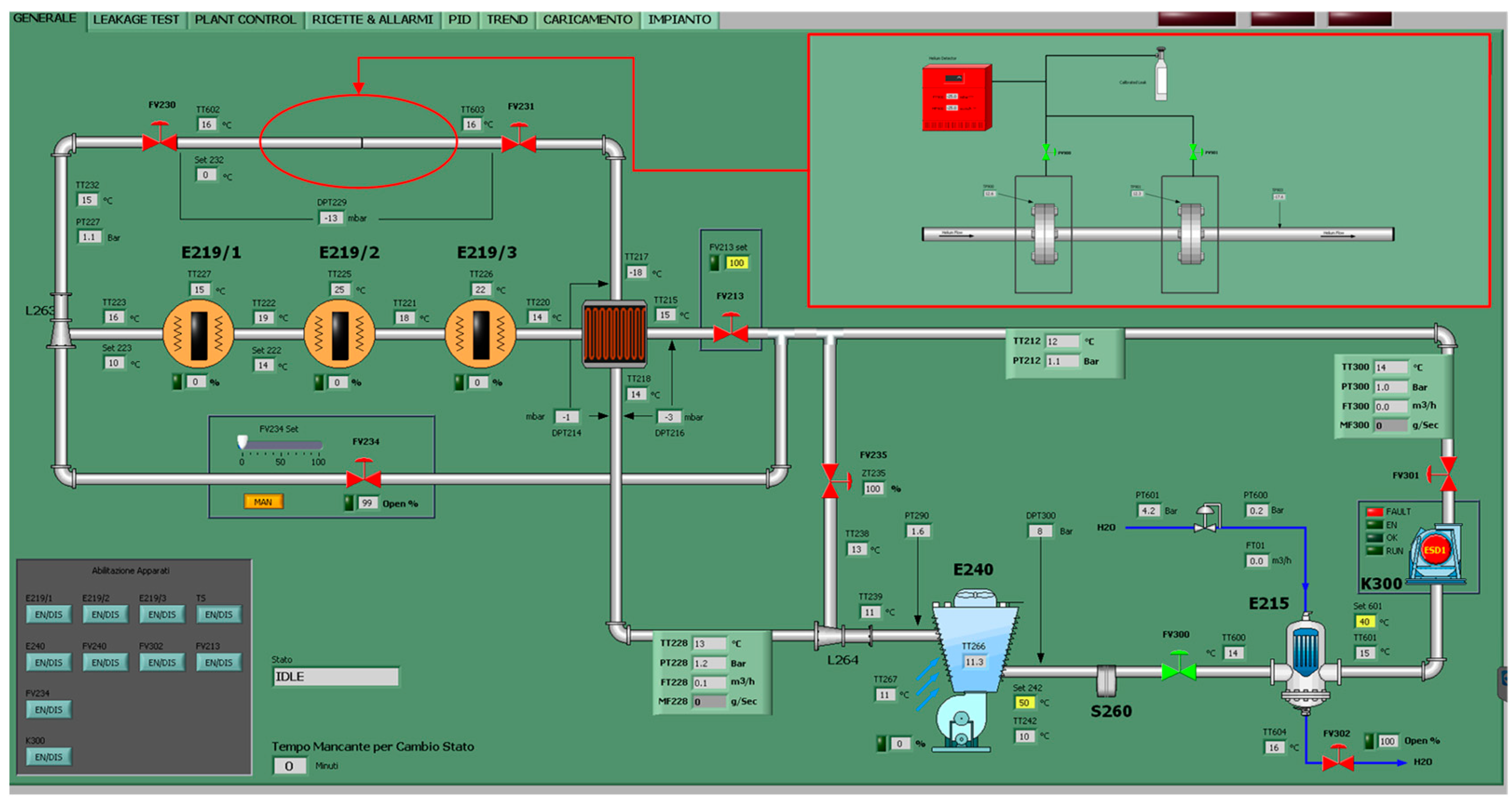
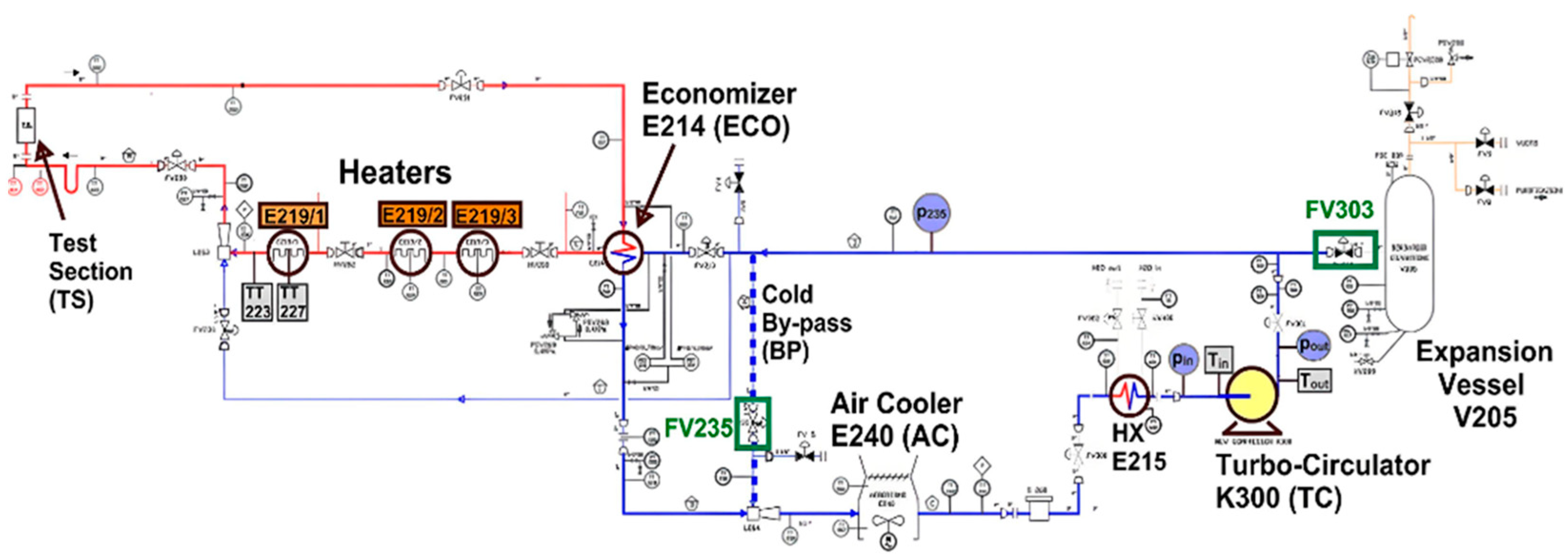
- The compressor, which is able to deliver a maximum flow-rate of 1.4 kg/s;
- Three electrical heaters, for a total power of 210 kW;
- Two cooling systems: a shell-and-tube helium–water heat exchanger (1 MW) and an air cooler (about 300 kW);
- A shell-and-tube helium–helium heat exchanger (economizer);
- The electrical cabinet, which is able to supply 1.3 MW.
- Long-term isothermal cooling flow;
- Slow thermal cycling flow;
- Fast cold thermal shock flow;
- LOCA/LOFA simulation.
3. Results
4. Discussion and Conclusions
Author Contributions
Funding
Data Availability Statement
Acknowledgments
Conflicts of Interest
References
- Galabert, J.; Hopper, D.; Neviere, J.-C.; Nodwell, D.; Pascal, R.; Poitevin, Y.; Ricapito, I.; White, G. Nuclear maintenance strategy and first steps for preliminary maintenance plan of the EU HCLL & HCPB Test Blanket Systems. Fus. Eng. Des. 2017, 116, 34–39. [Google Scholar]
- Damiani, C.; Palmer, J.; Takeda, N.; Annino, C.; Balagué, S.; Bates, P.; Bernal, S.; Cornellá, J.; Dubus, G.; Esqué, S.; et al. Overview of the ITER remote maintenance design and of the development activities in Europe. Fus. Eng. Des. 2018, 136, 1117–1124. [Google Scholar] [CrossRef]
- Ricapito; Calderoni, P.; Aiello, A.; Ghidersa, B.; Poitevin, Y.; Pacheco, J. Current design of the European TBM systems and implications on DEMO breeding blanket. Fus. Eng. Des. 2016, 109–111, 1326–1330. [Google Scholar] [CrossRef]
- Giancarli, L.M.; Bravo, X.; Cho, S.; Ferrari, M.; Hayashi, T.; Kim, B.-Y.; Leal-Pereira, A.; Martins, J.-P.; Merola, M.; Pascal, R.; et al. Overview of recent ITER TBM Program activities. Fus. Eng. Des. 2020, 158, 111674. [Google Scholar] [CrossRef]
- Wong, C.; Baxi, C.; Bourque, R.; Dahms, C.; Inamati, S.; Ryder, R.; Sager, G.; Schleicher, R. Helium cooling of fusion reactors. Fus. Eng. Des. 1994, 25, 249–262. [Google Scholar] [CrossRef]
- Farabolini, W.; Ciampichetti, A.; Dabbene, F.; Fütterer, M.; Giancarli, L.; Laffont, G.; Puma, A.L.; Raboin, S.; Poitevin, Y.; Ricapito, I.; et al. Tritium control modelling for a helium cooled lithium–lead blanket of a fusion power reactor. Fus. Eng. Des. 2006, 81, 753–762. [Google Scholar] [CrossRef]
- Fütterer, M.A.; Raepsaet, X.; Proust, E. Tritium permeation through helium-heated steam generators of ceramic breeder blankets for DEMO. Fus. Eng. Des. 1995, 29, 225–232. [Google Scholar] [CrossRef]
- Hernández, F.A.; Pereslavtsev, P.; Zhou, G.; Kang, Q.; D’amico, S.; Neuberger, H.; Boccaccini, L.V.; Kiss, B.; Nádasi, G.; Maqueda, L.; et al. Consolidated design of the HCPB Breeding Blanket for the pre-Conceptual Design Phase of the EU DEMO and harmonization with the ITER HCPB TBM program. Fus. Eng. Des. 2020, 157, 111614. [Google Scholar] [CrossRef]
- Cho, S.; Ahn, M.-Y.; Chun, Y.-B.; Gwon, H.; Jin, H.G.; Kim, B.S.; Kim, C.-S.; Kim, J.-I.; Kim, S.-K.; Ku, D.Y.; et al. Status of HCCR TBM program for DEMO blanket. Fus. Eng. Des. 2021, 171, 112553. [Google Scholar] [CrossRef]
- Barone, G.; Martelli, D.; Forgione, N.; Utili, M.; Ricapito, I. Experimental campaign on the upgraded He-FUS3 facility. Fus. Eng. Des. 2017, 123, 181–185. [Google Scholar] [CrossRef]
- Barone, G.; Coscarelli, E.; Forgione, N.; Martelli, D.; Del Nevo, A.; Tarantino, M.; Utili, M.; Ricapito, I.; Calderoni, P. Development of a model for the thermal-hydraulic characterization of the He-FUS3 loop. Fus. Eng. Des. 2015, 96–97, 212–216. [Google Scholar] [CrossRef]
- Tincani, A.; Aiello, A.; Ferrucci, B.; Granieri, M.; Voukelatou, K.; Ricapito, I.; Galabert, J.; Ortiz, C.; Arena, P.; Di Maio, P.A.; et al. Conceptual design of the enhanced coolant purification systems for the European HCLL and HCPB test blanket modules. Fus. Eng. Des. 2019, 146, 365–368. [Google Scholar] [CrossRef]

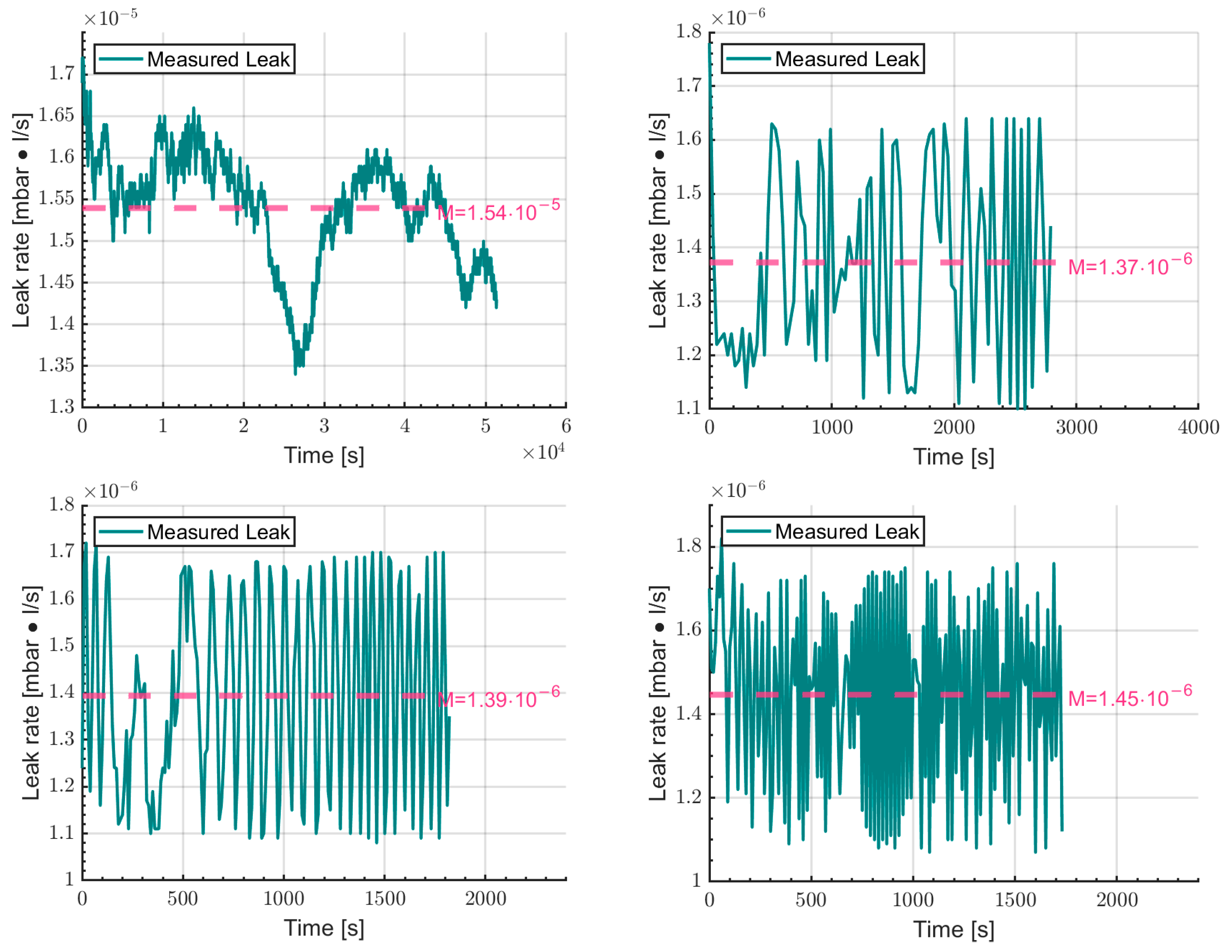

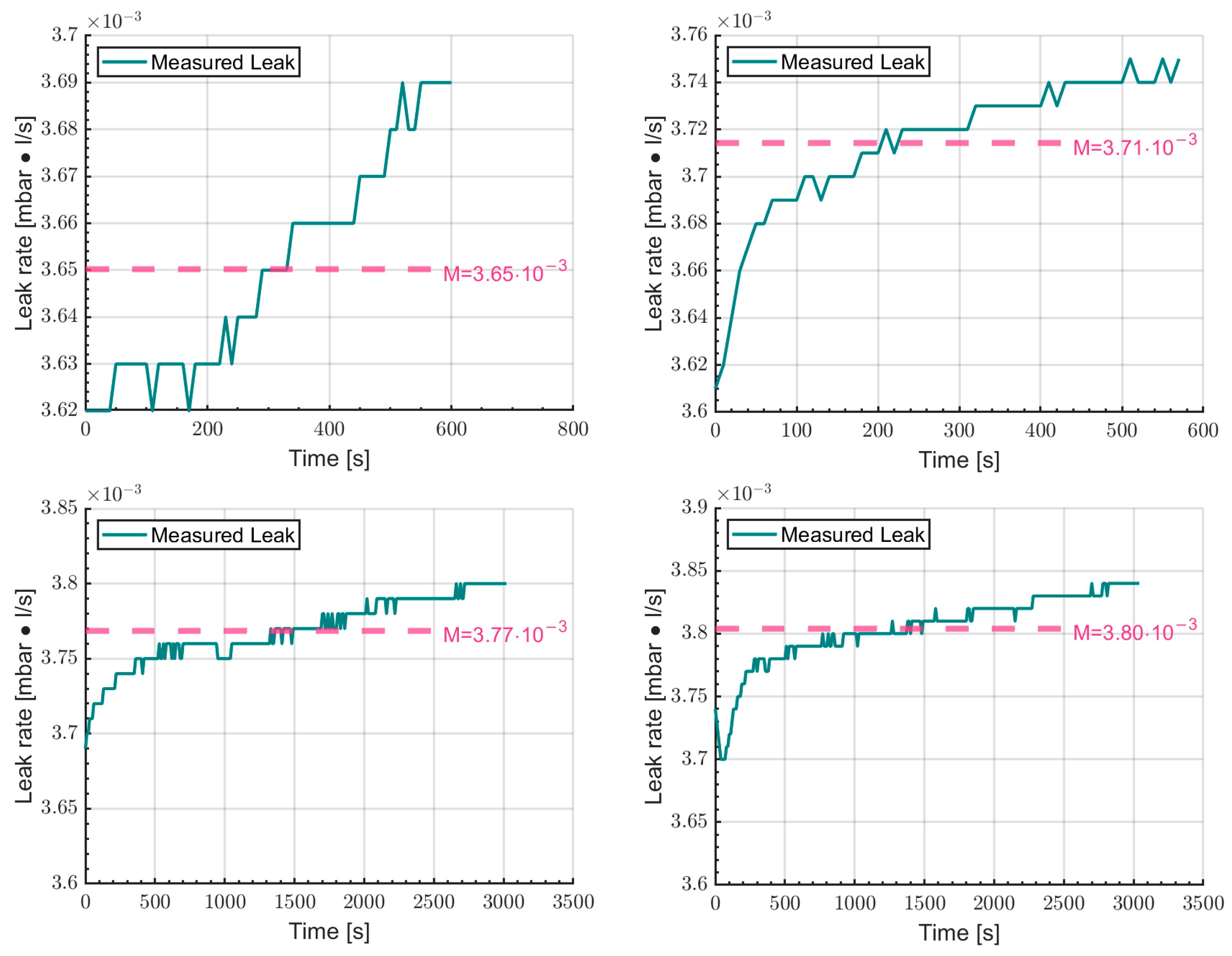
| Parameter | Value |
|---|---|
| Roughness | 8.0 μm |
| Angle of the inclined side | 22.5° |
| Depth | 7.9 mm |
| Width | 11.9 mm |
| Pitch diameter | 123.8 mm |
| Parameter | Value | Tolerance |
|---|---|---|
| Width of the ring | 11.13 mm | ±0.50 mm |
| Height of the ring | 17.53 mm | ±0.50 mm |
| Mean diameter | 123.83 mm | ±0.18 mm |
| Parameter | Value |
|---|---|
| Roughness | 250 μm |
| Height of a groove | 0.4 mm |
| Width of a groove | 0.8 mm |
| Number of grooves per inch | 50 |
| Parameter | Value | Tolerance |
|---|---|---|
| External diameter | 149.35 mm | ±0.8 mm |
| Width of the winding | 19.05 mm | ±0.8 mm |
| Internal diameter | 101.60 mm | ±0.4 mm |
| Thickness (winding) | 4.445 mm | ±0.127 mm |
| Thickness (ring) | 3.20 mm | ±0.105 mm |
| Test Number | P (bar) | Gasket T (°C) | He T (°C) | He Flow Rate (g/s) | Tested Gasket |
|---|---|---|---|---|---|
| 1 | 78.0 | 472 | 494 | 362 | oval ring joint |
| 2 | 80.0 | 461 | 490 | 362 | oval ring joint |
| 3 | 79.7 | 460 | 485 | 362 | oval ring joint |
| 4 | 79.6 | 458 | 483 | 361 | oval ring joint |
| 5 | 79.6 | 456 | 483 | 361 | oval ring joint |
| 6 | 80.0 | 482 | 491 | 360 | spiral wound |
| 7 | 80.0 | 482 | 492 | 360 | spiral wound |
| 8 | 80.0 | 482 | 492 | 360 | spiral wound |
| 9 | 79.6 | 484 | 493 | 360 | spiral wound |
Disclaimer/Publisher’s Note: The statements, opinions and data contained in all publications are solely those of the individual author(s) and contributor(s) and not of MDPI and/or the editor(s). MDPI and/or the editor(s) disclaim responsibility for any injury to people or property resulting from any ideas, methods, instructions or products referred to in the content. |
© 2023 by the authors. Licensee MDPI, Basel, Switzerland. This article is an open access article distributed under the terms and conditions of the Creative Commons Attribution (CC BY) license (https://creativecommons.org/licenses/by/4.0/).
Share and Cite
Venturini, A.; Papa, F.; Utili, M. Preliminary Experimental Quantification of Helium Leakages from Flanged Connections at HCPB TBS Operative Conditions. Energies 2023, 16, 5519. https://doi.org/10.3390/en16145519
Venturini A, Papa F, Utili M. Preliminary Experimental Quantification of Helium Leakages from Flanged Connections at HCPB TBS Operative Conditions. Energies. 2023; 16(14):5519. https://doi.org/10.3390/en16145519
Chicago/Turabian StyleVenturini, Alessandro, Francesca Papa, and Marco Utili. 2023. "Preliminary Experimental Quantification of Helium Leakages from Flanged Connections at HCPB TBS Operative Conditions" Energies 16, no. 14: 5519. https://doi.org/10.3390/en16145519
APA StyleVenturini, A., Papa, F., & Utili, M. (2023). Preliminary Experimental Quantification of Helium Leakages from Flanged Connections at HCPB TBS Operative Conditions. Energies, 16(14), 5519. https://doi.org/10.3390/en16145519


