Article

Development of Virtual Inertia Control with State-of-Charge Recovery Strategy Using Coordinated Secondary Frequency Control for Optimized Battery Capacity in Isolated Low Inertia Grid

1
Department of Electrical Engineering, Universitas Indonesia, Depok 16424, Indonesia
2
Department of Energy Systems Research, Ajou University, Suwon 01811, Republic of Korea
*
Author to whom correspondence should be addressed.
Energies 2023, 16(14), 5463; https://doi.org/10.3390/en16145463
Submission received: 26 June 2023 / Revised: 14 July 2023 / Accepted: 16 July 2023 / Published: 18 July 2023

Abstract

:
Integrating renewable energy through inverter-based generators has decreased the power system’s inertia. Reduced inertia may lead to frequency instability during power imbalance disturbances, particularly in an isolated power system with limited inertia. The Battery Energy Storage System (BESS) and a virtual inertia (VI) emulation control system have become popular to mitigate this issue. Nonetheless, the BESS utilization for VI emulation is highly dependent on the availability of BESS capacity, which may affect the energy cost. Therefore, developing a VI emulation control strategy that requires less energy and can recover the state of charge (SoC) to a desired level to optimize BESS utilization is required. This paper proposes a VI control with an SoC recovery strategy through coordination with the generators’ secondary frequency control. Instead of relying on the frequency, such as in the conventional approach, the controlled signal of the generators’ secondary frequency control also includes the VI power and BESS SoC. Hence, the generators can contribute to lowering the VI required energy and recovering the BESS SoC. The results show that the proposed method outperforms the conventional method by requiring around 36% lower energy and the ability to maintain the BESS SoC.

1. Introduction

1.1. Research Background

Renewable energy has become the preferred alternative source to generate electricity, since it is cleaner than fossil-based energy sources. Most prospective renewable energy sources for power generation include hydropower, solar energy through photovoltaic (PV) systems [1,2], wind energy [3,4], geothermal [5,6], biomass [7,8], tidal and wave energy [9,10], green hydrogen [11,12], etc. In 2021, the addition of renewable energy reached 280 GW, involving a higher addition of solar and wind energy, recorded at 19% and 12.5%, respectively [13]. Moreover, the penetration of renewable energy for electricity generation is predicted to increase in the future.
Renewable energy power plants can be implemented on the main grid or small-scale power systems, called isolated systems. The addition of renewable energy, especially those based on inverters in large grids, generally does not have a significant stability impact when a disturbance occurs if the percentage of renewable energy generation capacity connected in an on-grid configuration is still relatively small compared to the total generation capacity. Hence, the grid already has adequate reserve power to respond to disturbances. Different issues will occur if these kinds of renewable energy generation are integrated into smaller, isolated grids.
Integrating renewable energy sources into the grid through power electronic coupling, such as inverters, may reduce inertial capacity and lower the performance in responding to a supply–demand imbalance that occurs in the electric power system, which conventionally can be handled by a synchronous generator [14,15,16,17,18,19]. This imbalance will affect the systems’ frequency characteristics, such as more deviation of nadir frequency, steeper rate of change of frequency (RoCoF), more diversion of steady-state frequency, or even longer frequency settling time. These characteristics may trigger the protection scheme and cause a system blackout. Tielens et al. [20] reviewed the significance of inertia in power systems, stating that the inverter-dominated power system may behave differently than the conventional power system, especially under supply–demand imbalance disturbances. Moreover, it also brought up that isolated grids are more prone to frequency stability issues due to their limited rotational reserve capacities.
The inverter-based generation is predicted to exceed the number of rotational-based generations in the future [21,22,23]. Besides, when the microgrid system is implemented on large grids in the future, the same challenges will also arise when the microgrid must operate in an islanded mode. Hence, the microgrids are required to operate the electric power system independently, including supply and load balancing, voltage and frequency control, and power quality control. In fact, the generation capacity and its reserves will be limited when the microgrid is separated from the main grid, and the dominance of inverter-based generators will also reduce the inertial capacity of the microgrid system. These conditions will cause the system inertia to decrease and may lead to system instability during disturbances. Therefore, it is necessary to develop various methods and strategies to minimize the negative impact of inverter-based renewable power generation to maximize their integration into the power system. Specifically, such methods and strategies are highly required for isolated grids or islanded-mode microgrids with low inertia due to the increasing penetration of inverter-based renewable energy generations.
The Battery Energy Storage System (BESS) has been widely used to overcome the frequency instability challenges arising from a supply–demand imbalance in a low inertia power grid. The utilization of BESS for frequency regulation must consider both technical and economic aspects. BESS is still costly [24,25], and the ancillary service market for frequency regulation to enable the return of BESS investment is not fully deployed in many countries [26,27]. Thus, in the case of small and isolated grids, the required BESS investment might not be considered economically feasible. Therefore, this research aims to propose a frequency control strategy that can operate with a lower BESS capacity without neglecting its performance through BESS state-of-charge (SoC) recovery.

1.2. State-of-the-Art Review

Several strategies have been proposed to enhance the low inertia grid against the disturbances that lead to frequency instability. Cheng et al. [28] reviewed smart frequency control for low inertia energy systems, highlighting feasible solutions using the Battery Energy Storage System (BESS) and appropriate control strategies. In addition, the study also discussed the possible solutions to address the existing technique’s drawbacks to regulating the frequency during disturbances in low inertia power systems. Li et al. [29] proposed a strategy using combined superconducting magnetic energy storage (SMES) and BESS to overcome the frequency instability in microgrids by applying a power management strategy to extend the battery lifetime. In [30], case studies of using BESS for primary frequency control in high renewable energy penetration power systems were presented. It summarized the effect of different BESS parameters on frequency behavior.
Other methods for dealing with low inertia power systems have been developed, known as virtual inertia emulation/synthesis [31,32]. Virtual inertia emulation is a method to mimic the characteristics of rotating-mass inertia power so that it can contribute to the frequency response during a supply–demand imbalance. The superiority of VI emulations compared to the droop control was discussed in [33]. The recent development of VI emulation strategies has shown more advanced topology and control algorithms. Tamrakar et al. [34] described the existing topologies for virtual inertial control systems. Meanwhile, Kerdphol et al. [35] presented various control algorithms for virtual inertial synthesis.
An adaptive virtual and damping constant is a more advanced VI control strategy that can be implemented by using an adaptive fuzzy logic method [36,37,38]. In these works, the virtual and damping constants of the VI emulation system were dynamically changed following the frequency alteration. An adaptive fuzzy control method can supersede the fixed constant values so that the system can effectively respond to various types of disturbances and various renewable energy penetration levels. Moreover, a fractional order fuzzy controller also performed better under frequent supply–demand imbalances [39]. Based on these works, the fuzzy-based VI control strategy generally resulted in less frequency dip, such as better nadir frequency and low RoCoF. However, it is worth noting that this control method will cause BESS to absorb or generate power significantly compared to conventional methods. Thus, the BESS capacity in this control method may significantly increase, which may not be economically feasible for application in small and isolated grids.
Other control algorithms for VI emulations are by implementing a model predictive control (MPC) approach, such as in [40,41,42,43], or through the development of robust H-infinity (H∞), such as in [44,45,46]. The MPC operates by tuning the optimized virtual inertia and damping constants as a result of future event disturbance prediction. Whereas, the robust H-infinity controller included the uncertainty and disturbance factor in the system modeling to obtain an optimal solution for the control parameters. MPC and H-infinity applications for VI emulation result in a better nadir frequency, RoCoF, and faster settling time. However, the absorbed and discharged power from BESS become noticeably higher compared with the other control strategies, and thus, the required BESS capacity for its application also increases [35].
Utilization of BESS to generate or absorb virtual inertia power requires a specific BESS SoC [47,48,49]. Generally, the BESS SoC is set at 50%, so it will always have the power to supply the inertia power (discharging) or the available capacity to absorb the inertia power (charging). If the system frequency drops due to an increasing load or the trip of the generator, then BESS must have a certain energy capacity that can be released to withstand the decrease in frequency. On the other hand, if the system frequency increases, then BESS must have the capacity to quickly absorb excess power from the system. BESS over or under capacity may impact the performance and operation of the virtual inertia emulation system. Hence, BESS SoC management is required for an optimal virtual inertia emulation system. Furthermore, proper BESS SoC management may reduce the required BESS capacity to become more economical than without SoC management.
The literature mentioned previously did not address the necessity of recovering the BESS SoC. The performance of BESS in supporting the grid frequency during supply–demand imbalances was investigated in [47], and it revealed that the BESS SoC and the applied control strategy were crucial factors in enabling a reliable frequency response. Furthermore, that paper also introduced the effectiveness of any power source for primary frequency regulation using its proposed index, then used it to determine which power generators brought more benefit in regulating the frequency. The result showed that BESS was more effective for frequency support than conventional rotating generators, particularly in lower inertia and greater disturbances. Similarly, in [48], the importance of battery capacity in the frequency response application was emphasized, and it suggested that the BESS SoC can be recovered through the appropriate setting of the load frequency control (LFC). Besides, it examined the BESS performance in a power system where BESS capacity constrained was applied.
The SoC management, also known as the SoC recovery strategy, can be obtained in various methods. For instance, the simplest way to maintain the BESS SoC is through virtual inertia control parameters adjustment. This control method allows the BESS power to oscillate (charging/discharging) to recover its SoC [48]. Besides, the BESS SoC can also be recovered by adjusting the generators’ power if the SoC is lower or higher than a certain limit [50]. This method adopts a rule-based algorithm or appropriate thresholds to determine when BESS operates in charging or discharging mode. Various methods for SOC management have been proposed, namely through charge/discharge scheduling [51], deadband charging/discharging [52], online set-point setting [53,54], and MPC-based strategies [55]. Another method called the frequency-dependent state-of-charge recovery (FDSR) activates the charging/discharging mode using a set of rules that analyze the frequency and RoCoF [56]. However, these methods have some drawbacks, such as they may require higher power, and thus larger BESS capacity and longer stabilizing time. Besides, they may not optimally perform if successive disturbances occur in a short period.
Abazari et al. [57] showed some advantages of coordinating various energy resources in stand-alone microgrids to deal with frequency fluctuation. Their study proposed a solution for optimal BESS capacity and SoC recovery features. It divided the renewable energy resources to contribute to the frequency regulation based on their type and response characteristics, resulting in more optimized energy management. Each energy source cluster can be assigned to participate in either the primary frequency control, the SoC recovery, or both. Nonetheless, this method may be applied to those grids that have various types of energy resources. Mercier et al. [58] proposed a dynamic change in SoC limits to reduce the battery size and maintain its SoC. The SoC limits were determined through a sensitivity analysis applied to the economic optimization objective. It employed an iterative method to find the optimized solution for the SoC limits that maximized profit in utilizing the BESS for primary frequency regulation.
This study proposes a different approach for primary frequency control, particularly on the VI emulation system, that requires a lower BESS capacity through the SoC recovery strategy. The approach is applied by integrating the additional control signals on the secondary frequency control loop so that any generator participating in the secondary frequency regulation will also provide the VI power and recover BESS SoC within a shorter period. Moreover, the proposed strategy can also minimize the required absorbing/discharging power from BESS owing to the generator’s contribution during the disturbance. This research mainly focuses on an enhanced strategy for VI control by utilizing BESS in an isolated low inertia grid. The proposed method can reduce the required BESS capacity to provide VI power without neglecting its performance. The approach is by adjusting the generators’ secondary frequency control reference setting to include the VI power and BESS SoC signals. By doing this, the generators will respond not only solely based on the frequency deviation but also based on the status of VI power and BESS SoC.
The remainder of this paper is structured as follows: Section 2 describes the concept of frequency control and VI emulations; Section 3 elaborates the proposed control strategy that coordinates the BESS power and SoC, as well as the required power from conventional generators; Section 4 provides simulation case studies, the results, and the discussion. Lastly, this research is concluded in Section 5.

2. Frequency Control and Virtual Inertia Emulation

2.1. Frequency Control in Isolated Grid

Supply–demand imbalance in a power system leads to a frequency deviation from its nominal value (50 Hz or 60 Hz). This frequency deviation may affect the generation synchronization, cause damage or accelerated aging to the power system equipment, and lead to instability. Some protection schemes are employed if the frequency deviates further from its nominal value, which may force generation or load shedding and result in system blackouts. Therefore, various control mechanisms are applied to maintain the frequency within acceptable limits or bring it back to its nominal value by restoring the supply–demand balance in the power system.
The dynamic characteristics of the frequency change right after the disturbance, i.e., supply–demand imbalance, are shown in Figure 1, along with the corresponding control mechanism applied in a power system. In the figure, f 0 is the nominal value of the frequency (50 Hz or 60 Hz), f n indicates the maximum frequency deviation from the nominal value, known as nadir frequency, d f d t is the rate of change of frequency (RoCoF), f s s is the steady-state frequency due to the operation of primary control, and f s s is the final steady-state frequency after the operation of secondary and/or tertiary control. The nadir frequency is the worst frequency that occurred during the disturbance that deviates from the nominal value of 50 Hz, which can be mathematically expressed as follows:
f n = min f t t  
where f t is the frequency at time t. The acceptable range of the frequency deviation during disturbance is between 47.5 and 52.5 Hz at the basis of 50 Hz. Whereas, RoCoF is calculated based on an interval window of 100 ms [59], as follows:
R o C o F = d f d t = f t i + Δ t f t i Δ t t
where f t i is the frequency at the start of the disturbance ( t i ), and Δ t is the interval window. The acceptable RoCoF value may vary depending on the region and the applied grid code. This research employs a value of 1 p.u./s at a 50 Hz basis, or 0.5 Hz/s [60].
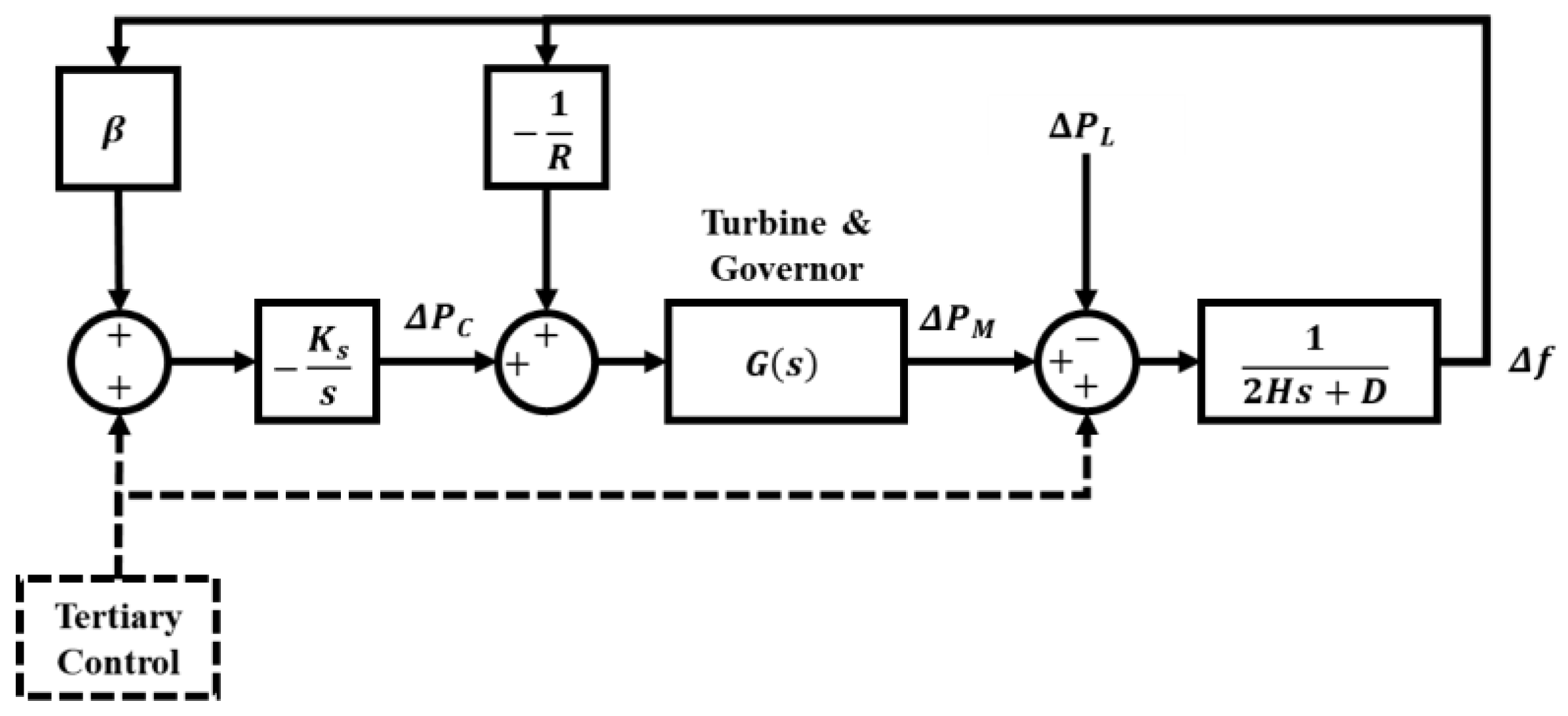
The control mechanisms commonly known and used in a power system include the primary, secondary, and tertiary control loops to overcome the frequency dynamics during a disturbance. Hence, the primary control includes the inertial response and governor control. Each control loop responds to a certain magnitude of frequency deviation within a particular duration, as shown in Figure 1, and the control loop diagram isolated grid is shown in Figure 2.
  • Inertial response. The inertial response is obtained from the kinetic energy stored in the rotating rotor mass, or better known as inertia, symbolized as H. It responds within seconds after the disturbances and serves to withstand sudden frequency changes to minimize the nadir frequency ( f n ) at a relatively higher value and the RoCoF ( d f d t ) at a relatively less steep value. It is worth noting that, with an increase of the inverter-based generator penetration, the value of system inertia is decreasing, and thus may reduce the system’s capability to maintain the nadir frequency as high as possible and the RoCoF as gently as possible. The correlation between system inertia and the frequency ( Δ f ) can be obtained from the swing equation in Laplace form, as follows:
    Δ f s = Δ P M s Δ P L s 2 H s + D
    where Δ P M is the change in the supply related to the mechanical power, Δ P L is the change in the demand/load, and H and D are the system inertia and damping coefficient, respectively.
  • Governor control. Governor control is usually provided in a generator, also known as droop control, symbolized as R. Governor control responds by adjusting the input power of the turbine proportionally to the droop setting. It works within milliseconds up to 30–40 s after disturbance to stabilize the frequency at a fixed and temporary frequency ( f s s ) before another control mechanism takes place. Hence, the governor control has limitations depending on the droop setting, so it can only operate within a certain range of frequency deviation ( f 0 ± Δ f p ). The effect of the governor control can be mathematically described as follows:
    Δ f s Δ P L s = 1 2 H s + D + 1 R G s
    where R is the droop setting of the governor, and G s is the transfer function of the generator that generates the mechanical power ( Δ P M ) and may vary depending on the turbine and governor characteristics.
  • Secondary control, also known as Load Frequency Control (LFC) or Automatic Generation Control (AGC). The LFC is aimed to bring back the frequency to its nominal value ( f s s = f 0 ) by adjusting the reference setting of the generators ( Δ P C ). It calculates the difference between the generated power and load and provides a new setting to the generators based on the integral control gain ( K s ) and frequency bias factor (β). This control mechanism operates within seconds to minutes after disturbances and responses to a certain range of frequency deviation ( f 0 ± Δ f s ) depending on the available power reserve in the system. The result of the LFC application can be evaluated as follows:
    Δ f s Δ P L s = 1 2 H s + D + 1 R G s + s β K s G s
    where K s is the integral control gain of LFC, and β is the frequency bias factor that depends on the damping coefficient and droop setting.
  • Tertiary control. The tertiary control is related to long-term frequency control, such as in minutes to hours, and is associated with power generation planning and emergency response. This adjustment is generally needed if the frequency continues to fall far below the nominal frequency, which can cause generator trips, cascading failures, and blackouts. It can respond within a tertiary frequency range ( f 0 ± Δ f t ), which is associated with the system’s overall power reserve, can be activated by turning on additional generation units, or by turning off a number of loads (load shedding). Hence, since this study discusses the short-term frequency characteristics after disturbances, so the tertiary control is not considered in this research.

2.2. Virtual Inertia Emulation Strategy

A virtual inertia emulation is a control strategy that manages the power conversion system’s output power to behave like a rotating rotor inertia. It converts the power from inverter-based generators, such as photovoltaic (PV) systems, wind turbines, or energy storage systems (ESS). The goal of virtual inertia emulation is to mimic the power response from the inertia, which is usually generated by a rotating rotor to help maintain the system frequency during disturbances. Generally, virtual inertia (VI) is obtained by adjusting the resulting power from the inverter-based power generation through a control mechanism, owing to the fast response capability of such power electronic devices. The virtual inertia emulation system works by supplying power at a faster tempo than the response of conventional generators under low inertia conditions. The frequency deviation is fed back to the control system’s input through the droop control mechanism to enhance the frequency and the rate of change of frequency (RoCoF) signals. Then, the control system, defined by the control parameters, such as the virtual inertia constant and virtual damping constant, will determine the output power of the BESS inverter, which is required for stabilizing the frequency.
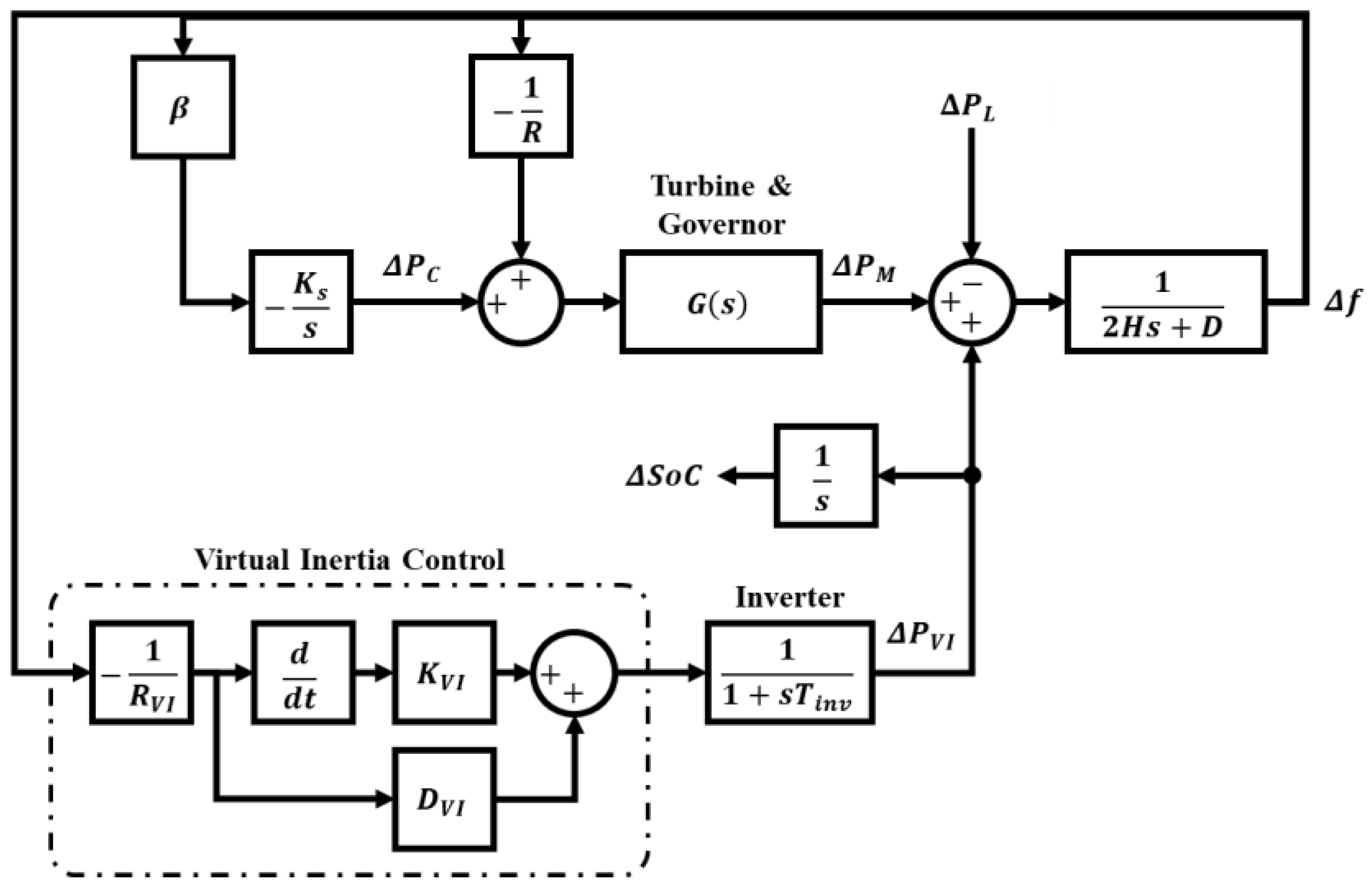
The virtual inertial emulation system consists of three (3) main components: an energy supply system, which can be an inverter-based generator, a Power Conversion System (PCS), and a control system. The general topology of the virtual inertial frequency control system can be seen in Figure 3. Whereas, the control block diagram of a virtual inertia emulation system in an isolated grid without tertiary control is presented in Figure 4.
In general, the emulation of virtual inertia can be built from the required inertial power ( Δ P V I ), which can be formulated as follows [35]:
Δ P V I = s K V I + D V I 1 + s T i n v Δ f s R V I
where K V I is the virtual inertia constant, D V I is the virtual damping constant, T i n v is the inverter’s time constant, and R V I is the virtual inertia droop setting. In this case, the output power can be positive if the system is required to supply the virtual inertia power or negative if the system is required to absorb the excess power. The amount of output power ( P V I ) will be subject to the energy availability in BESS, defined as BESS SoC ( Δ S o C ), which can be calculated as an integral of the change in virtual inertia power, as follows:
Δ S o C = 1 s Δ P V I
In [61], an enhanced derivative control technique for VI emulation was used for frequency regulation in microgrids, and it pointed out the relevance of the VI control parameters on VI emulation performances. A high virtual inertia constant will give less nadir frequency deviation and lower RoCoF, but it needs more power and may cause a longer settling time. On the other hand, a low virtual damping constant, which has an inverse dimension with a virtual inertia constant, will bring benefit on a faster settling time and require less power, but it will increase the nadir frequency deviation and RoCoF. Hence, this work has shown that the proposed technique was able to optimize the VI emulation performance through derivative-based coordination between the constants. An optimization algorithm with the objective called the constrained and regularized H 2 norm minimization problem was proposed in [62], which intended to determine the most optimized virtual and damping constant for Virtual Synchronous Machine (VSM). It considered the frequency response requirements and calculated the coefficient values through an efficient gradient method. Whereas, a heuristic algorithm, such as the whale optimization algorithm (WOA), was used in [63] to determine the optimal virtual and damping constants by minimizing the frequency deviation.

3. Coordinated Virtual Inertia Control Strategy

3.1. Characteristics of VI Control

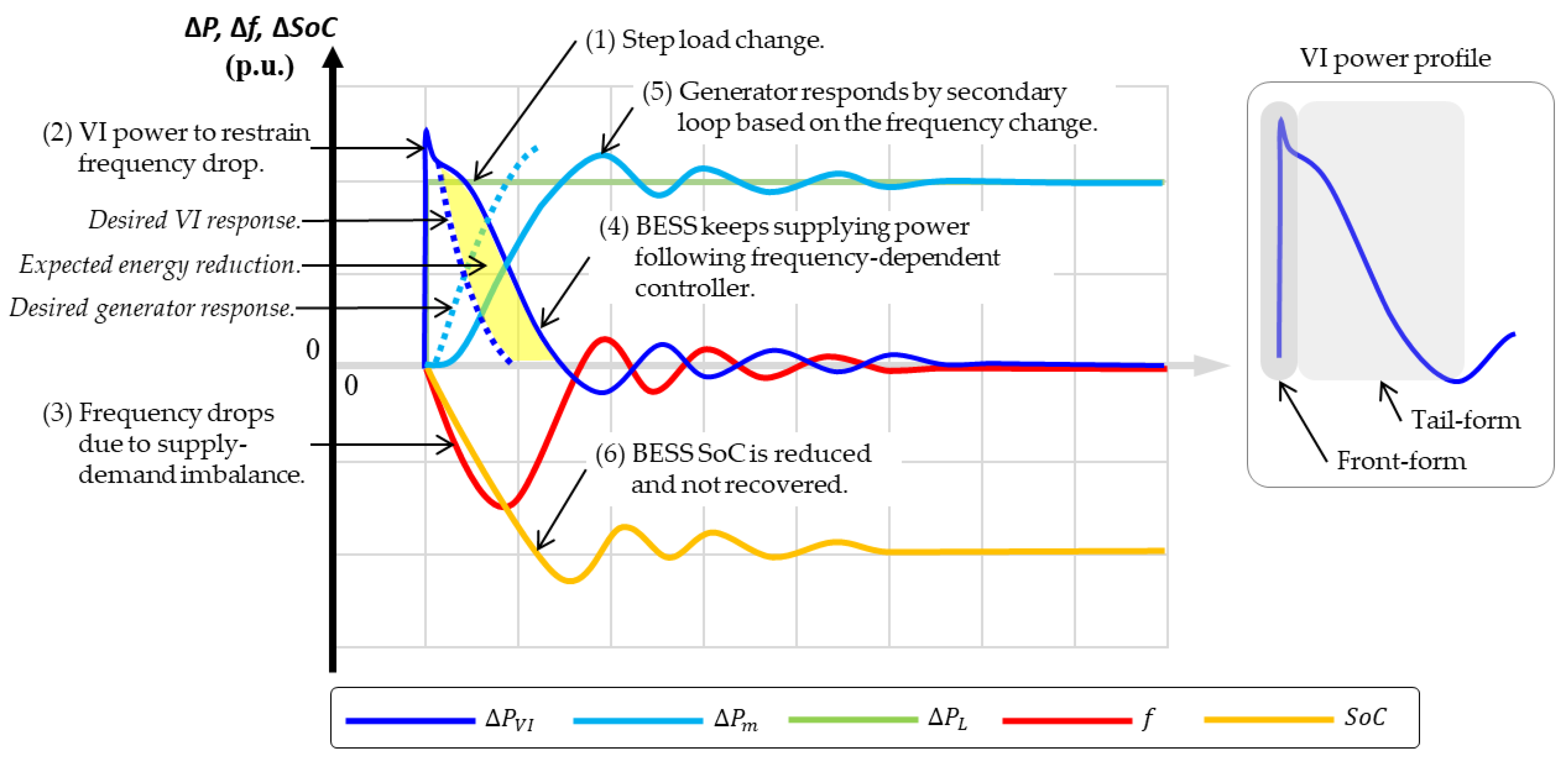
The VI control works by emulating the required power during disturbances, and it has the operational characteristics shown in Figure 5. First, when a disturbance occurs (modeled as step load change) in an isolated system, the VI will quickly respond to that change by providing almost instantaneous power to restrain the frequency drop. The VI will continue to supply power to the system based on the frequency change. Similarly, the generator will start responding, which is controlled by its secondary frequency loop. The steady-state frequency can be achieved after several minutes, depending on the value of the secondary frequency gain. Hence, both VI emulation and the generator’s secondary frequency control perform based on the frequency (frequency-dependent). In addition, the BESS SoC will be reduced, because it discharges power to the system and will not be recovered solely by the existing control strategy.
In Figure 5, the profile of VI power can be divided into front-form and tail-form. Front-form is associated with the required power to improve the frequency during disturbances, which is the expected operating performance from a VI emulation. Meanwhile, the tail-form is the additional power that follows the frequency-dependent controller. At the beginning of a disturbance, the VI front-form causes a lower frequency deviation that slows down the generator’s secondary control response. The VI tail-form may not be necessary because the generator can manage the power imbalance. Therefore, a proper control strategy can modify the behavior of VI and the generator’s secondary control such that the VI only participates at the beginning of a disturbance and charges/discharges power as minimum as possible in the tail-form period to give the generator a chance to increase/decrease the power. By doing this, the BESS capacity can be optimized, as shown in yellow in Figure 5.

3.2. Modified Secondary Frequency Control Signal

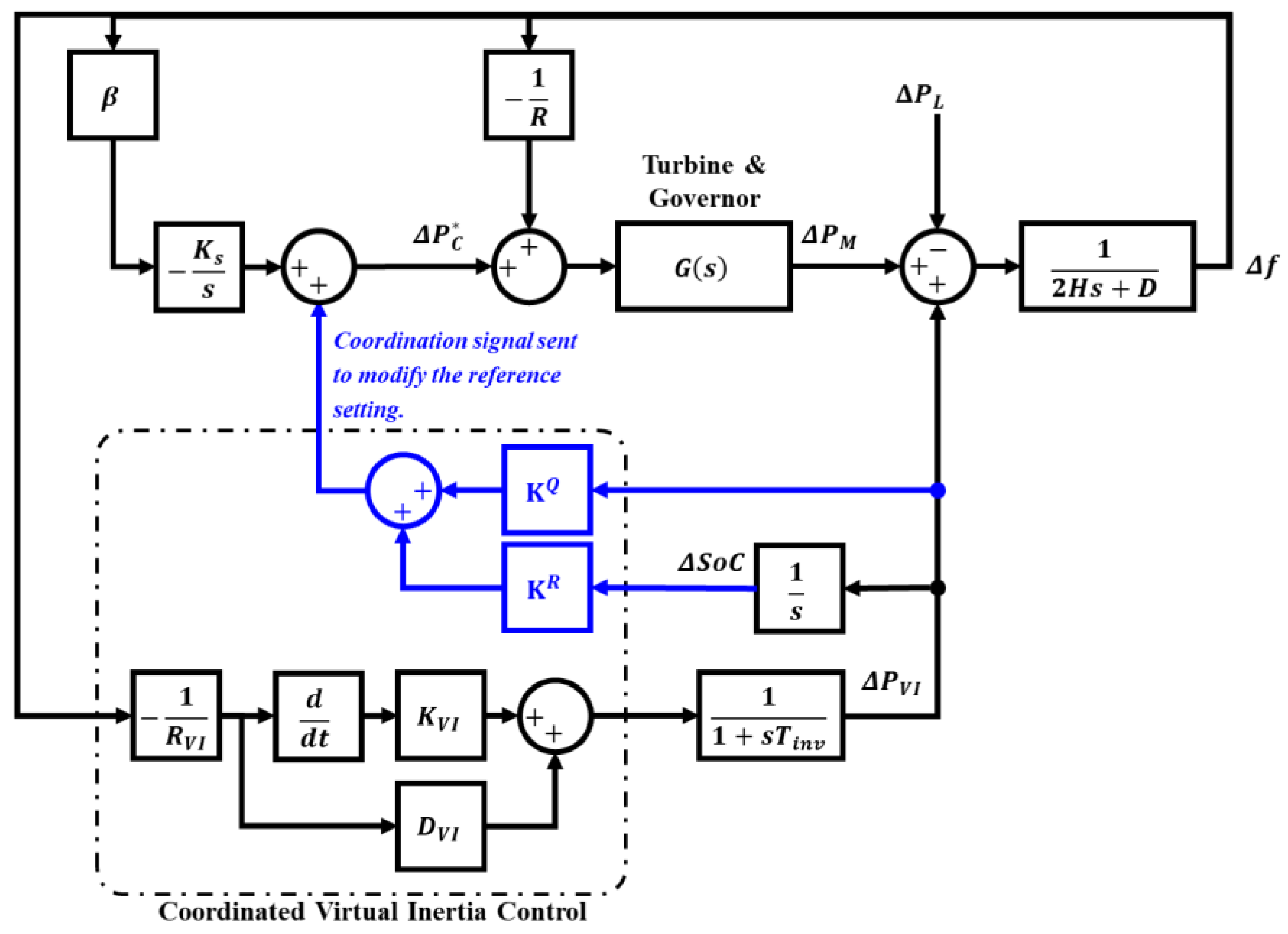
This research proposes a control strategy that coordinates the secondary frequency control operation with the virtual inertia control. Hence, the secondary frequency control, or LFC, is forced to supply the power with the virtual inertia and manage the BESS SoC. The LFC sets the generator output power to manage the power delivered/absorbed by BESS. By doing this, the virtual inertia emulation system will only be responsible for a shorter period right after disturbance (front-form), requiring less energy. Consecutively, the LFC will balance the supply and demand while suppressing the power from BESS and even recovering the BESS SoC.
The conventional VI and generator’s secondary frequency control are frequency-dependent. It means that the output power of VI and the generator will be determined by the frequency and the controller’s parameters. The proposed strategy in this research is to incorporate additional controlled signals to the secondary loop to coordinate with the VI performance. These additional controlled signals are the VI power and the BESS SoC. The VI power and BESS SoC are fed to adjust the reference setting of the generator’s secondary control. Hence, the generator’s response will depend not only on the frequency but also on the VI performance and the BESS SoC. Moreover, the BESS SoC signal will instruct the generator to recover the SoC to the nominal value.
The transfer function formulation for coordinated strategy considers the amount of virtual inertia power and the required virtual inertia energy. This strategy will modify the control signal that is conventionally and solely based on the frequency value. Originally, the reference setting ( Δ P C ) obtained from the LFC is defined as follows:
Δ P C = β K s s Δ f s
and by incorporating the control signal from the primary frequency control (droop setting), the generator will generate the required power to stabilize the supply and demand, thus the frequency. The additional controlled signals, namely, the VI power ( Δ P V I ) and BESS SoC ( Δ S o C ), are added to determine the reference value, as follows:
Δ P C = β K s s Δ f s + Κ Q Δ P V I s + Κ R Δ S o C s
where Δ P C is the modified reference signal of the generator, taking into account the VI power and BESS SoC, and Κ Q and Κ R are the controller’s parameters. Hence, the controller’s parameter, Κ Q and Κ R , can be developed by using various control algorithms, such as Proportional–Integral–Derivative (PID) or proportional–integral (PI) controller, fuzzy logic, or MPC. This paper uses a PI controller to provide an understanding of the proposed strategy.
The control block diagram of the coordinated virtual inertia control–secondary frequency control is shown in Figure 6. The generated virtual inertia power signal and the BESS SoC status are fed back and processed to adjust the reference setting of the secondary frequency control. The control parameters, Κ Q and Κ R , are utilized to modify the behavior of the virtual inertia power supplied by BESS. This method allows BESS through VI control to only provide the necessary inertia power for a shorter period (front-form), either by discharging or charging the power, and the generators will continue to manage the system’s required power so that VI’s contribution will be minimized, and the energy capacity can be reduced. Besides, the generator will also increase or decrease power at the steady-state period for SoC recovery operation. The selection of the control parameters determines the amount of energy reduction from BESS for VI service and the period of SoC recovery after the disturbance.
The VI emulation system configuration with the respected power electronics converter is presented in Figure 7. The system consists of the BESS as an energy provider completed with the DC-to-AC converter with Pulse-Width Modulation (PWM) control. The PWM control receives the signal from the proposed VI control to determine the required amount of VI power to deliver or absorb. The VI control also sends a coordination signal to the Generator Control Panel (GCP) to determine the modified reference setting of the secondary frequency control of the generators. In addition, the VI control receives the input signal, such as the BESS SoC, the output power of the converter (VI power), and the system’s frequency.

4. Simulation and Results

4.1. Test Case System and Study Cases

The simulation is carried out by utilizing a general model of an isolated power system with low inertia with the parameter values provided in Table 1. For the base case system, the total system’s inertia is 10 s, and the total system’s damping is 2 Hz. Following the integration of inverter-based power generation, these values will be decreased and may cause frequency instability. In addition, the generation rate constraint (GRC) and the signal time delay are also applied, such as 0.3 p.u./s and 1 s, respectively [64,65].
The study cases in this research are simulated by considering the extreme change in total loads in the power system. The following formula assumes the maximum load change in an isolated power system: At regular operation, the generator is generally loaded at 60% of its rated capacity, so the maximum available power reserve is 40% of its rated capacity. Thus, considering the generator’s maximum loading of 90% of the rated capacity, the maximum permitted load change is 30% of the rated capacity, which is 50% of the normal operating load (0.5 p.u.). Suppose the change in load occurs beyond this assumption, the system will shut down due to a shortage of supply reserves, and this condition is outside the scope of this research problem, because it is related to the power system planning and requires the action of tertiary control.
The simulations will be carried out and analyzed for various scenarios to provide a comprehensive understanding of the importance of inertia and damping in a power system and the significance of providing frequency regulation, such as VI emulation and maintaining the BESS SoC. Therefore, the simulation will start with a base case system with higher and lower total inertia and damping, the effect of the application of the secondary frequency control, and the performance of the VI emulation with the proposed method. The simulation with the conventional method approach will also be provided and analyzed as a comparison.
The proposed VI control with SoC recovery strategy is evaluated and compared with other existing strategies based on several criteria, such as the frequency performances, including the nadir frequency and RoCoF, the SoC after the virtual inertia operates, and the required BESS capacity that is analyzed based on the maximum energy absorbed/discharged by BESS. In its use as frequency support, BESS capacity shall be maintained at around half of its maximum capacity so that BESS can absorb power (charging) when there is a sudden excess supply or discharge power (discharging) when there is a sudden supply deficit.

4.2. Results and Discussion

The performance of the base case in high and low inertia and damping without the implementation of secondary frequency control and the application of the VI emulation is presented in Figure 8. The reduction in the total system’s inertia and damping due to the inverter-based power generation is assumed to be 50% of the base case’s values. It can be seen that the system with a higher system’s inertia and damping results in a higher nadir frequency (47.06 Hz) and better RoCoF (−1.24 Hz/s) than a system with the lower one ( f n = 45.5 Hz and RoCoF = −2.49 Hz/s). In addition, the steady-state frequency with higher and lower inertia is 48.84 Hz and 48.79 Hz, respectively, which can be achieved in 102 s and 122 s, respectively. These results show the significance of the system inertia and damping in maintaining the system’s frequency during disturbances.
Figure 9 shows a similar case but with the activation of secondary frequency control. It can be seen that the nadir frequency and the RoCoF are not changed, but the steady-state frequency can be brought back to the nominal value of 50 Hz. Hence, the secondary frequency control activation does not improve the nadir frequency and the RoCoF.
The system’s frequency in isolated low inertia grid during supply–demand imbalance disturbances can be improved by implementing the VI emulation with BESS as the power supply. The performance characteristics of the VI implementation are evaluated for different virtual inertia and damping parameters, and the secondary frequency gain will be remained as activated. From this case forward, the simulation will be performed with total system inertia and damping of 50% of the base case.
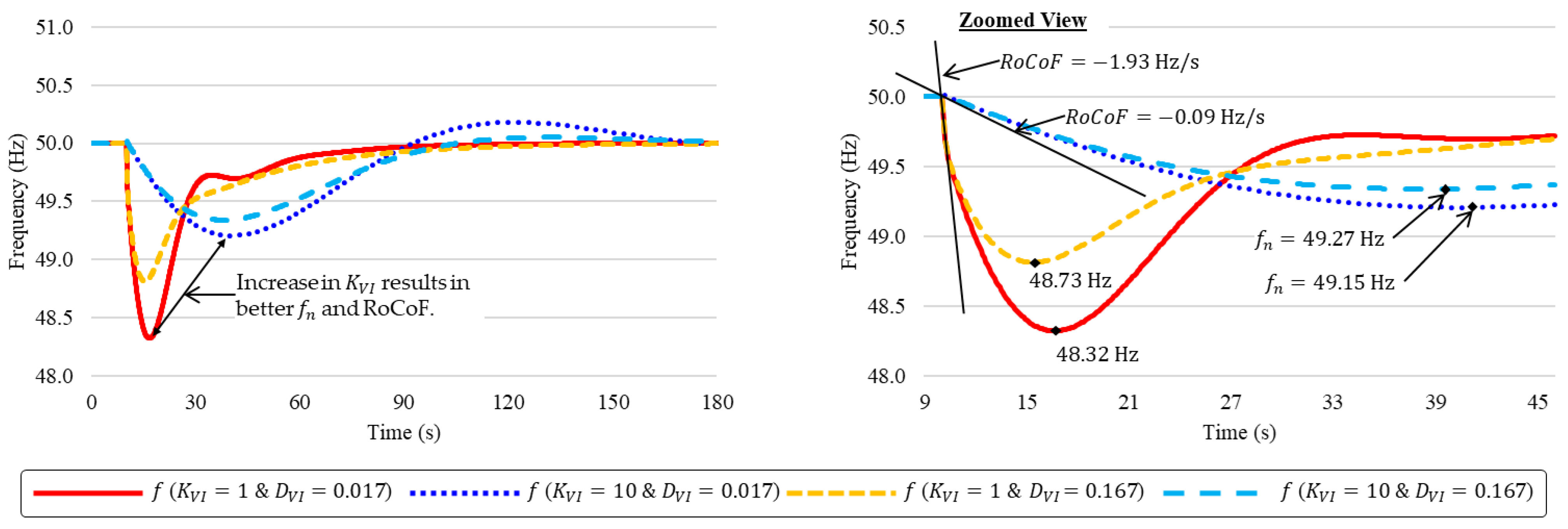
Figure 10 presents the system’s frequency profile, which shows that the increasing virtual inertia constant may improve the nadir frequency and RoCoF. Whereas, Figure 11 presents the system’s power and BESS SoC profiles. It is shown that the VI energy supplied by BESS will be higher when the virtual damping constant is increased. These results conclude that, to achieve the desired performance, such as better nadir frequency and RoCoF, as well as less energy consumption from BESS and obtain BESS SoC recovery, it needs a higher virtual inertia constant and lower virtual damping constant, as shown in Figure 11b. Figure 11b results in a nadir frequency of 49.15 Hz, RoCoF of −0.09 Hz/s, a maximum energy consumption of 9 p.u.-s, and SoC recovery to −1.4 p.u.-s (84% of the consumed energy).
A PID/PI control on the secondary frequency control and a conventional VI control can also improve performance in terms of nadir frequency, RoCoF, BESS energy capacity, and SoC recovery. In this case, the virtual inertia and damping constant of the VI emulation are set to 7 and 0.01, respectively. Whereas, the proportional and integral constants of secondary frequency PI control are set to 100 and 4, respectively. The result of this approach is presented in Figure 12. It shows that the nadir frequency can be as high as 49.62 Hz with a RoCoF of −0.12 Hz/s.
Moreover, the total energy consumed from BESS is only at 3.1 p.u.-s, and the BESS SoC can be recovered to −0.5 p.u.-s (84% of the consumed energy). Even though the enhanced control method is applied at the generator’s secondary frequency control and the BESS consumed energy becomes lower than the previous method, the BESS SoC does not return to the nominal value (i.e., 0.5 p.u.). This condition occurs because the control system is frequency-dependent, which will settle once the frequency approaches a controlled value. In order to recover the BESS SoC to a desired level, its setting value must be provided to the control system, as proposed by this research.
The proposed strategy coordinates the control signal on the secondary frequency control through a VI emulation control system. It provides a proper reference signal for the generator to behave by considering the system’s frequency, the VI power, and the BESS SoC status. Therefore, the proposed control strategy can outperform conventional control strategies in frequency profile, VI energy capacity required, and BESS SoC recovery, as shown in Figure 13. The virtual inertia constant ( K V I ) and virtual damping constant ( D V I ) utilized in this simulation are 7 and 3.5, respectively. Whereas, the proposed VI power control parameters ( Κ Q ) employ PID control with a proportional gain of 1.5 and an integral gain of 0.3; the proposed SoC recovery control ( Κ R ) is set to 0.02. The nadir frequency obtained is 49.9 Hz, and RoCoF is −0.1 Hz/s. Meanwhile, the consumed energy from BESS is only 2.6 p.u.-s, and the BESS SoC is fully recovered.
Table 2 compares the proposed method with the conventional methods using a step load change of 0.5 p.u. based on frequency profile (nadir frequency and RoCoF), BESS capacity, and BESS SoC recovery. It can be seen from the table that the proposed method results in the highest nadir frequency (49.9 Hz) compared to other methods (49.15 Hz in the standard method and 49.62 Hz in the PI control of the secondary loop). The resulting RoCoF in all methods is slightly different, such as −0.09 Hz/s, −0.12 Hz/s, and −0.10 Hz/s in standard, PI control secondary loop, and the proposed method, respectively. The required BESS capacity in the proposed method is the lowest (2.6 p.u.-s) compared to other methods (9 p.u.-s and 3.1 p.u.-s). Whereas, the proposed method shows an ability to recover the SoC to the nominal value by 100% instead of 84% in other methods. Hence, the proposed method has outperformed the other conventional methods.
Random load variations in a more extended period will be used to evaluate the performance and robustness of the proposed method. The construction of random load variations considers the load variability, intermittency, and uncertainty of renewable power generations. For demand variation, a combined random 30 min change with a magnitude of 0.25 p.u., 15 min change with a magnitude of 0.1 p.u., and a random 1 min change with a magnitude of 0.05 p.u. will be applied. Meanwhile, for renewable energy production variation, a combined random 10 min change with a magnitude of 0.2 p.u. and a random 1 min change with a magnitude of 0.1 p.u. will be applied. Moreover, this random load variation will be simulated for 4 h and 6 h, and the profiles are presented in Figure 14 and Figure 15.
The simulation result for random load variation for 4 h and 6 h are presented in Figure 16 and Figure 17. In the 4 h simulation, the frequency deviation (red and light red) when using the proposed method is in the range of 49.95 Hz and 50.04 Hz, compared with the conventional method, which lies in the range of 49.81 Hz and 50.16 Hz. In the 6 h simulation, the frequency deviation is between 49.96 and 50.03 Hz, compared with 49.84 and 50.11 Hz in the conventional method. The steepest RoCoF recorded in the 4 h simulation is 0.056 Hz/s using the proposed method and 0.066 Hz/s using the conventional method. Meanwhile, it is 0.047 Hz/s (proposed method) and 0.056 Hz/s (conventional method) in the 6 h simulation. Hence, the proposed method is superior to the conventional method in terms of the ability to maintain the frequency.
The required VI power (blue and light blue) is almost similar in both methods, which means that the VI is responsible for the early period of disturbance. The highest power absorbed/supplied to the system is 0.354 p.u. (4 h simulation) and 0.301 p.u. (6 h simulation) in the conventional method, while it is 0.357 p.u. (4 h simulation) and 0.304 p.u. (6 h simulation) by using the proposed methods. In addition, the generator operates to satisfy the power imbalance (green and light green), while the VI operates to restrain a sudden change.
The proposed method in the 4 h simulation requires a maximum BESS capacity of 0.98 p.u.-s, which is 37.6% less than the one required by the conventional method (1.57 p.u.-s). On the other hand, the required maximum BESS capacity by using the proposed method is 36.8% less than the conventional method (0.84 p.u.-s compared to 1.33 p.u.-s). Lastly, the proposed method is able to recover almost 100% of the energy consumed from BESS to provide the VI power (purple) in both random simulations. Meanwhile, the conventional method hardly recovers the BESS SoC to the nominal value (light purple). Hence, despite a slightly different result value due to random load characteristics, the proposed method consistently reduces the required BESS capacity and can restore the BESS SoC to its nominal value.

5. Conclusions

This paper highlighted the significance of inertia in a power system, particularly in an isolated grid where the reserve power capacity is limited. The integration of inverter-based renewable energy generation into an isolated grid will even lower the system’s inertia. This condition will lead to frequency instability if a disturbance, such as a supply–demand imbalance, occurs in the system and may force the system to black out. One of the efforts to mitigate such an event is implementing virtual inertia (VI) emulation using the Battery Energy Storage System (BESS). The BESS utilization for VI emulation might be costly for an isolated grid operator. Therefore, it is required to provide as low as possible BESS capacity without neglecting the desired VI performance. In addition, a mechanism is required to return the BESS state of charge (SoC) to the nominal level so it can be consistently ready to absorb or supply the required VI power every time a disturbance occurs.
This paper has proposed a strategy for VI control with an SoC recovery strategy by modifying the reference control signal of the existing conventional rotating generators. It employed three controlled signals, such as the frequency deviation, the VI power, and the SoC status, to the control system. In this case, the VI emulation will operate to restrain a further frequency drop, and the generator will be responsible for regulating the power imbalance, resulting in a minimum power required by the VI system from BESS. In addition, the generator will also adjust its output to include the required power to recover the BESS SoC.
The result showed that the proposed strategy can outperform the conventional method intending to regulate the frequency profile (nadir frequency and RoCoF) with minimum energy from BESS and the capability to recover the BESS SoC. By applying a long period of random load variation, the proposed strategy is better in nadir frequency and RoCoF, but requires around 36% less BESS capacity and can restore 100% of BESS energy compared with the conventional method.
Despite the proposed control’s benefits, some implications for future attempts must be considered, such as the compatibility of the existing grid to adopt the VI emulation system, the coordination of various control technologies in the grid, and the adjustments to the existing frequency and voltage regulations. These issues can be considered for future work in the area of VI emulation systems.

Author Contributions

Conceptualization, F.H.J. and I.G.; methodology, F.H.J. and J.J.; simulation, F.H.J.; resources, F.H.J. and B.S.; validation, B.S., I.G., and J.J.; writing—original draft preparation, F.H.J.; writing—review and editing, B.S., I.G., and J.J.; visualization, F.H.J.; supervision, I.G.; funding acquisition, I.G. All authors have read and agreed to the published version of the manuscript.

Funding

This research was funded by Universitas Indonesia Research Grant for International Publication 2022/2023, contract number: NKB-1147/UN2.RST/HKP.05.00/2022.

Data Availability Statement

The data presented in this study are available in the body of this paper.

Conflicts of Interest

The authors declare no conflict of interest. The funders had no role in the design of the study; in the collection, analyses, or interpretation of data; in the writing of the manuscript, or in the decision to publish the results.

Nomenclature

AGCAutomatic Generation Control
BESSBattery Energy Storage System
GRCGeneration Rate Constraint
LFCLoad Frequency Control
MPCModel Predictive Control
PIProportional–integral
PIDProportional–integral–derivative
RESRenewable Energy Sources
RoCoFRate of Change of Frequency
SoCState of Charge
VIVirtual Inertia

References

  1. Ahmad, L.; Khordehgah, N.; Malinauskaite, J.; Jouhara, H. Recent advances and applications of solar photovoltaics and thermal technologies. Energy 2020, 207, 118254. [Google Scholar] [CrossRef]
  2. Jean, J.; Brown, P.R.; Jaffe, R.L.; Buonassisi, T.; Bulović, V. Pathways for solar photovoltaics. Energy Environ. Sci. 2015, 8, 1200–1219. [Google Scholar] [CrossRef]
  3. Gallego-Castillo, C.; Cuerva-Tejero, A.; Lopez-Garcia, O. A review on the recent history of wind power ramp forecasting. Renew. Sustain. Energy Rev. 2015, 52, 1148–1157. [Google Scholar] [CrossRef] [Green Version]
  4. Jung, J.; Broadwater, R.P. Current status and future advances for wind speed and power forecasting. Renew. Sustain. Energy Rev. 2014, 31, 762–777. [Google Scholar] [CrossRef]
  5. Chamorro, C.R.; Mondéjar, M.E.; Ramos, R.; Segovia, J.J.; Martín, M.C.; Villamañán, M.A. World geothermal power production status: Energy, environmental and economic study of high enthalpy technologies. Energy 2012, 42, 10–18. [Google Scholar] [CrossRef]
  6. Santos, L.; Dahi Taleghani, A.; Elsworth, D. Repurposing abandoned wells for geothermal energy: Current status and future prospects. Renew. Energy 2022, 194, 1288–1302. [Google Scholar] [CrossRef]
  7. Malico, I.; Nepomuceno Pereira, R.; Gonçalves, A.C.; Sousa, A.M.O. Current status and future perspectives for energy production from solid biomass in the European industry. Renew. Sustain. Energy Rev. 2019, 112, 960–977. [Google Scholar] [CrossRef]
  8. Hameed, Z.; Aslam, M.; Khan, Z.; Maqsood, K.; Atabani, A.E.; Ghauri, M.; Khurram, M.S.; Rehan, M.; Nizami, A.-S. Gasification of municipal solid waste blends with biomass for energy production and resources recovery: Current status, hybrid technologies and innovative prospects. Renew. Sustain. Energy Rev. 2021, 136, 110375. [Google Scholar] [CrossRef]
  9. Khojasteh, D.; Mousavi, S.M.; Glamore, W.; Iglesias, G. Wave energy status in Asia. Ocean Eng. 2018, 169, 344–358. [Google Scholar] [CrossRef]
  10. Li, G.; Zhu, W. Tidal current energy harvesting technologies: A review of current status and life cycle assessment. Renew. Sustain. Energy Rev. 2023, 179, 113269. [Google Scholar] [CrossRef]
  11. Shang, Z.; Hossain, M.M.; Wycisk, R.; Pintauro, P.N. Poly(phenylene sulfonic acid)-expanded polytetrafluoroethylene composite membrane for low relative humidity operation in hydrogen fuel cells. J. Power Sources 2022, 535, 231375. [Google Scholar] [CrossRef]
  12. Zhou, Y.; Li, R.; Lv, Z.; Liu, J.; Zhou, H.; Xu, C. Green hydrogen: A promising way to the carbon-free society. Chin. J. Chem. Eng. 2022, 43, 2–13. [Google Scholar] [CrossRef]
  13. IRENA. Renewable Capacity Statistics 2022; IRENA: Abu Dhabi, United Arab Emirates, 2022. [Google Scholar]
  14. IRENA. Renewable Energy Prospects: Indonesia; a REmap analysis; IRENA: Abu Dhabi, United Arab Emirates, 2017. [Google Scholar]
  15. Katiraei, F.; Agüero, J.R. Solar PV integration challenges. IEEE Power Energy Mag. 2011, 9, 62–71. [Google Scholar] [CrossRef]
  16. Bird, L.; Milligan, M.; Lew, D. Integrating Variable Renewable Energy: Challenges and Solutions; National Renewable Energy Lab. (NREL): Golden, CO, USA, 2013.
  17. Rokrok, E.; Shafie-khah, M.; Catalão, J.P.S. Review of primary voltage and frequency control methods for inverter-based islanded microgrids with distributed generation. Renew. Sustain. Energy Rev. 2018, 82, 3225–3235. [Google Scholar] [CrossRef]
  18. Rampokanyo, M.; Ijumba-Kamera, P. Power system inertia in an inverter-dominated network. J. Energy South. Afr. 2019, 30, 80–86. [Google Scholar] [CrossRef]
  19. Ulbig, A.; Borsche, T.S.; Andersson, G. Impact of Low Rotational Inertia on Power System Stability and Operation. IFAC Proc. Vol. 2014, 47, 7290–7297. [Google Scholar] [CrossRef]
  20. Tielens, P.; Van Hertem, D. The relevance of inertia in power systems. Renew. Sustain. Energy Rev. 2016, 55, 999–1009. [Google Scholar] [CrossRef]
  21. Islam, M.A.; Hasanuzzaman, M.; Rahim, N.A.; Nahar, A.; Hosenuzzaman, M. Global renewable energy-based electricity generation and smart grid system for energy security. Sci. World J. 2014, 2014, 197136. [Google Scholar] [CrossRef] [Green Version]
  22. Hartono, B.S.; Budiyanto; Setiabudy, R. Review of Microgrid Technology. In Proceedings of the 2013 International Conference on QiR, Yogyakarta, Indonesia, 25–28 June 2013; pp. 127–132. [Google Scholar] [CrossRef]
  23. Mamat, R.; Sani, M.S.M.; Sudhakar, K. Renewable Energy in Southeast Asia: Policies and Recommendations. Sci. Total Environ. 2019, 670, 1095–1102. [Google Scholar] [CrossRef]
  24. IRENA. Electricity Storage and Renewables: Costs and Markets to 2030; IRENA: Abu Dhabi, United Arab Emirates, 2017. [Google Scholar]
  25. IRENA. Battery Storage for Renewables: Market Status and Technology Outlook; IRENA: Abu Dhabi, United Arab Emirates, 2015. [Google Scholar]
  26. Berrada, A.; Loudiyi, K.; Zorkani, I. Valuation of energy storage in energy and regulation markets. Energy 2016, 115, 1109–1118. [Google Scholar] [CrossRef]
  27. Cho, J.; Kleit, A.N. Energy storage systems in energy and ancillary markets: A backwards induction approach. Appl. Energy 2015, 147, 176–183. [Google Scholar] [CrossRef]
  28. Cheng, Y.; Azizipanah-Abarghooee, R.; Azizi, S.; Ding, L.; Terzija, V. Smart frequency control in low inertia energy systems based on frequency response techniques: A review. Appl. Energy 2020, 279, 115798. [Google Scholar] [CrossRef]
  29. Li, J.; Yang, Q.; Yao, P.; Sun, Q.; Zhang, Z.; Zhang, M.; Yuan, W. A Novel use of the Hybrid Energy Storage System for Primary Frequency Control in a Microgrid. Energy Procedia 2016, 103, 82–87. [Google Scholar] [CrossRef]
  30. Amin, M.R.; Negnevitsky, M.; Franklin, E.; Alam, K.S.; Naderi, S.B. Application of battery energy storage systems for primary frequency control in power systems with high renewable energy penetration. Energies 2021, 14, 1379. [Google Scholar] [CrossRef]
  31. Kerdphol, T.; Rahman, F.S.; Mitani, Y. Virtual inertia control application to enhance frequency stability of interconnected power systems with high renewable energy penetration. Energies 2018, 11, 981. [Google Scholar] [CrossRef] [Green Version]
  32. Skiparev, V.; Machlev, R.; Chowdhury, N.R.; Levron, Y.; Petlenkov, E.; Belikov, J. Virtual inertia control methods in islanded microgrids. Energies 2021, 14, 1562. [Google Scholar] [CrossRef]
  33. Ofir, R.; Markovic, U.; Aristidou, P.; Hug, G. Droop vs. Virtual Inertia: Comparison from the Perspective of Converter Operation Mode. In Proceedings of the 2018 IEEE International Energy Conference (ENERGYCON), Limassol, Cyprus, 3–7 June 2018; pp. 1–6. [Google Scholar] [CrossRef] [Green Version]
  34. Tamrakar, U.; Shrestha, D.; Maharjan, M.; Bhattarai, B.P.; Hansen, T.M.; Tonkoski, R. Virtual inertia: Current trends and future directions. Appl. Sci. 2017, 7, 654. [Google Scholar] [CrossRef] [Green Version]
  35. Kerdphol, T.; Rahman, F.S.; Watanabe, M.; Mitani, Y. Virtual Inertia Synthesis and Control; Springer: Cham, Switzerland, 2021; ISBN 9783030579609. [Google Scholar]
  36. Kerdphol, T.; Watanabe, M. Self-Adaptive Virtual Inertia Control-Based Fuzzy Logic to Improve Frequency Stability of Microgrid with High Renewable Penetration. IEEE Access 2019, 7, 76071–76083. [Google Scholar] [CrossRef]
  37. Karimi, A.; Khayat, Y.; Naderi, M.; Dragičević, T.; Mirzaei, R.; Blaabjerg, F.; Bevrani, H. Inertia Response Improvement in AC Microgrids: A Fuzzy-Based Virtual Synchronous Generator Control. IEEE Trans. Power Electron. 2020, 35, 4321–4331. [Google Scholar] [CrossRef]
  38. Yang, L.; Hu, Z. Implementation of dynamic virtual inertia control of supercapacitors for multi-area PV-based microgrid clusters. Sustainability 2020, 12, 3299. [Google Scholar] [CrossRef] [Green Version]
  39. Mahto, T.; Kumar, R.; Malik, H.; Hussain, S.M.S.; Ustun, T.S. Fractional order fuzzy based virtual inertia controller design for frequency stability in isolated hybrid power systems. Energies 2021, 14, 1634. [Google Scholar] [CrossRef]
  40. Kerdphol, T.; Rahman, F.S.; Mitani, Y.; Hongesombut, K. Virtual Inertia Control-Based Model Predictive Control for Microgrid Frequency Stabilization Considering High Renewable Energy Integration. Sustainability 2017, 9, 773. [Google Scholar] [CrossRef] [Green Version]
  41. Saleh, A.; Hasanien, H.M.; Turky, R.A.; Turdybek, B.; Alharbi, M.; Jurado, F.; Omran, W.A. Optimal Model Predictive Control for Virtual Inertia Control of Autonomous Microgrids. Sustainability 2023, 15, 5009. [Google Scholar] [CrossRef]
  42. Zheng, C.; Dragicevic, T.; Blaabjerg, F. Model Predictive Control-Based Virtual Inertia Emulator for an Islanded Alternating Current Microgrid. IEEE Trans. Ind. Electron. 2021, 68, 7167–7177. [Google Scholar] [CrossRef]
  43. Mohamed, T.H.; Bevrani, H.; Hassan, A.A.; Hiyama, T. Decentralized model predictive based load frequency control in an interconnected power system. Energy Convers. Manag. 2011, 52, 1208–1214. [Google Scholar] [CrossRef]
  44. Kerdphol, T.; Rahman, F.S.; Mitani, Y.; Watanabe, M.; Kufeoglu, S. Robust Virtual Inertia Control of an Islanded Microgrid Considering High Penetration of Renewable Energy. IEEE Access 2018, 6, 625–636. [Google Scholar] [CrossRef]
  45. Amiri, F.; Moradi, M.H. Designing a new robust control for virtual inertia control in the microgrid with regard to virtual damping. J. Electr. Comput. Eng. Innov. 2020, 8, 53–70. [Google Scholar] [CrossRef]
  46. Moradi, M.H.; Amiri, F. Virtual inertia control in islanded microgrid by using robust model predictive control (RMPC) with considering the time delay. Soft Comput. 2021, 25, 6653–6663. [Google Scholar] [CrossRef]
  47. Arrigo, F.; Bompard, E.; Merlo, M.; Milano, F. Assessment of primary frequency control through battery energy storage systems. Int. J. Electr. Power Energy Syst. 2020, 115, 105428. [Google Scholar] [CrossRef] [Green Version]
  48. Borsche, T.S.; Ulbig, A.; Andersson, G. Impact of frequency control reserve provision by storage systems on power system operation. IFAC Proc. Vol. 2014, 19, 4038–4043. [Google Scholar] [CrossRef] [Green Version]
  49. Sockeel, N.; Gafford, J.; Papari, B.; Mazzola, M. Virtual Inertia Emulator-Based Model Predictive Control for Grid Frequency Regulation Considering High Penetration of Inverter-Based Energy Storage System. IEEE Trans. Sustain. Energy 2020, 11, 2932–2939. [Google Scholar] [CrossRef]
  50. Kunisch, H.-J.; Kramer, K.G.; Dominik, H. Battery Energy Storage Another Option for Load-Frequency-Control and Instantaneous Reserve. IEEE Trans. Energy Convers. 1986, EC-1, 41–46. [Google Scholar] [CrossRef]
  51. Chang, J.-W.; Lee, G.-S.; Moon, H.-J.; Glick, M.B.; Moon, S.-I. Coordinated Frequency and State-of-Charge Control with Multi-Battery Energy Storage Systems and Diesel Generators in an Isolated Microgrid. Energies 2019, 12, 1614. [Google Scholar] [CrossRef] [Green Version]
  52. Oudalov, A.; Chartouni, D.; Ohler, C. Optimizing a battery energy storage system for primary frequency control. IEEE Trans. Power Syst. 2007, 22, 1259–1266. [Google Scholar] [CrossRef]
  53. Borsche, T.; Ulbig, A.; Koller, M.; Andersson, G. Power and energy capacity requirements of storages providing frequency control reserves. In Proceedings of the 2013 IEEE Power & Energy Society General Meeting, Vancouver, BC, Canada, 21–25 July 2013. [Google Scholar] [CrossRef]
  54. Mégel, O.; Mathieu, J.L.; Andersson, G. Maximizing the potential of energy storage to provide fast frequency control. In Proceedings of the IEEE PES ISGT Europe 2013, Lyngby, Denmark, 6–9 October 2013; pp. 1–5. [Google Scholar] [CrossRef]
  55. Ulbig, A.; Rinke, T.; Chatzivasileiadis, S.; Andersson, G. Predictive control for real-time frequency regulation and rotational inertia provision in power systems. In Proceedings of the 52nd IEEE Conference on Decision and Control, Firenze, Italy, 10–13 December 2013; pp. 2946–2953. [Google Scholar] [CrossRef]
  56. Datta, U.; Kalam, A.; Shi, J. Battery energy storage system for aggregated inertia-droop control and a novel frequency dependent state-of-charge recovery. Energies 2020, 13, 2003. [Google Scholar] [CrossRef] [Green Version]
  57. Abazari, A.; Monsef, H.; Wu, B. Coordination strategies of distributed energy resources including FESS, DEG, FC and WTG in load frequency control (LFC) scheme of hybrid isolated micro-grid. Int. J. Electr. Power Energy Syst. 2019, 109, 535–547. [Google Scholar] [CrossRef]
  58. Mercier, P.; Cherkaoui, R.; Oudalov, A. Optimizing a battery energy storage system for frequency control application in an isolated power system. IEEE Trans. Power Syst. 2009, 24, 1469–1477. [Google Scholar] [CrossRef]
  59. Gonzalez-Longatt, F.; Roldan-Fernandez, J.M.; Chamorro, H.R.; Arnaltes, S.; Rodriguez-Amenedo, J.L. Investigation of inertia response and rate of change of frequency in low rotational inertial scenario of synchronous dominated system. Electronics 2021, 10, 2288. [Google Scholar] [CrossRef]
  60. ENTSO-E. Inertia and Rate of Change of Frequency (RoCoF); ENTSO-E: Brussels, Belgium, 2020. [Google Scholar]
  61. Kerdphol, T.; Rahman, F.S.; Watanabe, M.; Mitani, Y.; Turschner, D.; Beck, H.P. Enhanced Virtual Inertia Control Based on Derivative Technique to Emulate Simultaneous Inertia and Damping Properties for Microgrid Frequency Regulation. IEEE Access 2019, 7, 14422–14433. [Google Scholar] [CrossRef]
  62. Ademola-Idowu, A.; Zhang, B. Optimal design of virtual inertia and damping coefficients for virtual synchronous machines. In Proceedings of the 2018 IEEE Power & Energy Society General Meeting (PESGM), Portland, OR, USA, 5–10 August 2018. [Google Scholar]
  63. Faragalla, A.; Abdel-Rahim, O.; Orabi, M.; Abdelhameed, E.H. Enhanced Virtual Inertia Control for Microgrids with High-Penetration Renewables Based on Whale Optimization. Energies 2022, 15, 9254. [Google Scholar] [CrossRef]
  64. Mohajeryami, S.; Neelakantan, A.R.; Moghaddam, I.N.; Salami, Z. Modeling of deadband function of governor model and its effect on frequency Response characteristics. In Proceedings of the 2015 North American Power Symposium (NAPS), Charlotte, NC, USA, 4–6 October 2015. [Google Scholar] [CrossRef]
  65. Morsali, J.; Zare, K.; Tarafdar Hagh, M. Appropriate generation rate constraint (GRC) modeling method for reheat thermal units to obtain optimal load frequency controller (LFC). In Proceedings of the 2014 5th Conference on Thermal Power Plants (CTPP), Tehran, Iran, 10–11 June 2014; 2015; pp. 29–34. [Google Scholar] [CrossRef]
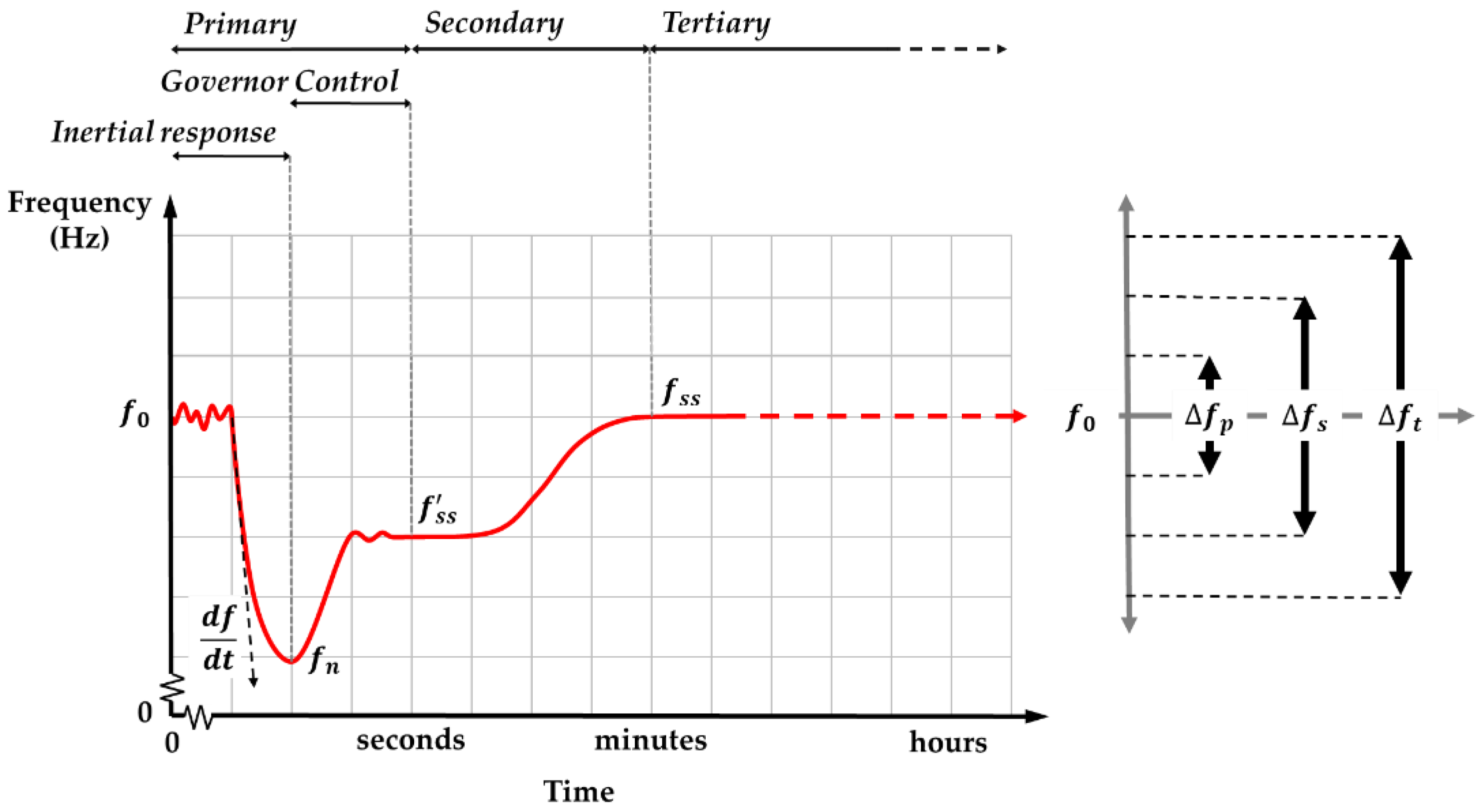
Figure 1. Frequency characteristics and control mechanism in power systems during disturbances. Primary control responses to the deviation of ± Δ f p within 30 s, secondary control responses to the deviation of ± Δ f s within seconds up to minutes, and tertiary control responses to the deviation of ± Δ f t within minutes up to hours.
Energies 16 05463 g001
Figure 2. Frequency control mechanism for the isolated grid. The primary frequency control loop regulates the frequency based on the droop setting (R), and the frequency control loop regulates the frequency based on integral control gain ( K s ) and frequency bias factor (β) to result in a new reference setting ( Δ P C ). The tertiary control in an isolated grid is mostly used for power generation planning and emergency purposes.
Energies 16 05463 g002
Figure 3. Topology of a virtual inertia emulation system. It comprises an energy supply system, PCS, and a control system.
Energies 16 05463 g003
Figure 4. Isolated grid with VI control block diagram. It reads the frequency signal and develops a control signal through virtual inertia constant using frequency derivative and virtual damping constant using frequency. The change in SoC is determined through an integrator of virtual inertia power.
Energies 16 05463 g004
Figure 5. Illustration of VI operation characteristics showing the VI power, generator’s power, frequency, and the BESS SoC. The generator and VI are operating based on the system’s frequency profile. Generally, the VI power profile can be divided into front-form and tail-form.
Energies 16 05463 g005
Figure 6. Coordinated virtual inertia control–secondary frequency control. A control signal is sent to adjust the reference power setting of the secondary frequency control ( Δ P C ) based on the frequency change ( Δ f ), VI power ( Δ P V I ), and BESS SoC ( Δ S o C ). Κ Q and Κ R are the coordinated control parameters that optimize VI power and the BESS capacity.
Energies 16 05463 g006
Figure 7. Configuration of the proposed VI control with power electronics converter. The proposed VI control inputs are the converter ( P V I ) output power, the system frequency (f), and the BESS SoC. The outputs are the signal sent to the converter’s PWM to instruct the amount of power to deliver/absorb and the coordination signal sent to the generator control panel (GCP) to instruct the required power from the generator.
Energies 16 05463 g007
Figure 8. The frequency profile of the test case system without secondary frequency control and VI emulations. The blue color employs 100% of inertia and damping, and the red color employs 50% of inertia and damping. The system with higher inertia results in a higher nadir frequency and gentle RoCoF. The steady-state frequency remains around 48.8 Hz for both scenarios since the secondary frequency control is not yet activated.
Energies 16 05463 g008
Figure 9. The frequency profile of the test case system with secondary frequency control but without VI emulation. The blue color employs 100% of inertia and damping, and the red color employs 50%. The system with higher inertia results in a higher nadir frequency and gentle RoCoF. The steady-state frequency is recovered to 50 Hz in both scenarios.
Energies 16 05463 g009
Figure 10. Frequency profile with the implementation of VI emulation. A higher virtual inertia constant provides better nadir frequency and RoCoF.
Energies 16 05463 g010
Figure 11. Power and BESS SoC profile with the implementation of VI emulation. (a) Virtual inertia constant of 1 s and virtual damping constant of 0.017 Hz/s, (b) Virtual inertia constant of 10 s and virtual damping constant of 0.017 Hz/s, (c) Virtual inertia constant of 1 s and virtual damping constant of 0.167 Hz/s, (d) Virtual inertia constant of 10 s and virtual damping constant of 0.167 Hz/s. A lower virtual damping constant provides less energy consumption.
Energies 16 05463 g011
Figure 12. System frequency, VI power, and BESS SoC with a PI/PID secondary frequency control combined with conventional VI control. A higher virtual inertia constant results in better nadir frequency and RoCoF, while a PI control at the secondary frequency control results in a lower BESS energy consumption and better SoC recovery.
Energies 16 05463 g012
Figure 13. System frequency, VI power, and BESS SoC with a proposed method. The system has a better nadir frequency and RoCoF, consumes less BESS energy, and recovers BESS SoC to the nominal level.
Energies 16 05463 g013
Figure 14. Profile of 4 h random load variations that represents the change in load and renewable energy generations. The magnitude variation is smaller within a shorter interval and will be more significant in a longer interval.
Energies 16 05463 g014
Figure 15. Profile of 6 h random load variations that represents the change in load and renewable energy generations. The magnitude variation is smaller within a shorter interval and will be more significant in a longer interval.
Energies 16 05463 g015
Figure 16. Performance comparison between the conventional and proposed methods (4 h random load variations). The frequency profile in the proposed method (red) is better than in the conventional method (light red). The absorbed/supplied VI power is close in both the proposed method (blue) and conventional method (light blue), indicating that the VI is dealing with the required period of disturbance. The required BESS energy capacity in the proposed method (purple) is less than in the conventional method (light purple), and BESS SoC can be recovered to the nominal value in the proposed method.
Energies 16 05463 g016
Figure 17. Performance comparison between the conventional and proposed methods (6 h random load variations). The frequency profile in the proposed method (red) is better than in the conventional method (light red). The absorbed/supplied VI power is close in both the proposed method (blue) and conventional method (light blue), indicating that the VI is dealing with the required period of disturbance. The required BESS energy capacity in the proposed method (purple) is less than in the conventional method (light purple), and BESS SoC can be recovered to the nominal value in the proposed method.
Energies 16 05463 g017
Table 1. Test case system parameter. The system’s inertia and damping value without renewable energy penetration are 10 s and 0.5 Hz, respectively. These values will be decreased once the inverter-based power generation is integrated. The setting value of the secondary gain constant will also be adjusted.
ParameterUnitValue
Total system inertia, Hs10
Total system damping, DHz2
Governor time constant, T G -5
Turbine time constant, T T -0.5
Droop setting, R%5
Secondary gain constant, K s -0.8
Secondary bias factor, β-1
Generation Rate Constraint, GRCp.u./s0.3
Signal time delay, TDs1
Table 2. Performance comparison between the conventional method and the proposed method. The proposed method can outperform the conventional method regarding nadir frequency, RoCoF, BESS capacity, and BESS SoC recovery.
ParameterUnitStandard MethodPI Control MethodProposed Method
Nadir frequencyHz49.1549.6249.9
RoCoFHz/s−0.09−0.12−0.10
Maximum BESS capacityp.u.-s93.12.6
SoC recovery%8484100
Disclaimer/Publisher’s Note: The statements, opinions and data contained in all publications are solely those of the individual author(s) and contributor(s) and not of MDPI and/or the editor(s). MDPI and/or the editor(s) disclaim responsibility for any injury to people or property resulting from any ideas, methods, instructions or products referred to in the content.