1. Introduction
The fourth industrial revolution (4IR) has introduced a change in how energy is generated, transmitted, and distributed. Faheem et al. [
1] explain that the method of generating energy is moving towards alternative green energy sources like solar, tidal and wind generators. This movement is due to the growing energy demand and the ability of the centralized power distribution network (CPDN) to provide stable power to meet this demand, which is introducing a growing number of microgrids that can supplement the shortfall from the CPDN. As a result, decentralized microgrids are becoming increasingly more common, which is also confirmed by Yin et al. [
2]. Janko et al. [
3] state that the distributed energy resources through microgrids globally are expected to increase from 132.4 GW to 528.4 GW between 2017 and 2026.
Decentralized microgrids are using renewable energy sources due to the environmental impact of fossil fuels. However, the main drawback of renewable energy is that energy generation is not constant, and the energy demand varies. Therefore, microgrids should be able to store energy to compensate for the difference in supply, demand, and future use. Nizami et al. [
4] confirm that microgrids can store energy more effectively by using multiple types of batteries in a hybrid model that includes chemical batteries (lead Acid, lithium-based, and nickel-based). Other battery types include mechanical batteries (flywheel energy storage (FES)), superconductive magnetic energy storage (SMES), and supercapacitor energy storage systems (SCES), as per Xin et al. [
5].
Faheem et al. [
1] further identify a change in transmission and distribution towards decentralized systems. The recent development of geographically distributed subsystems of microgrids (MG) supports this change. However, the decentralized MG system is complex and dynamic. It, therefore, requires the capability to use advanced information and communication technology (ICT) and intelligent information process (IIP) to monitor and control energy generation, transmission, and distribution. This capability evolves the MG system into a smart microgrid (SMG) network.
The SMG network provides energy to end-users (consumers) and themselves as prosumers.
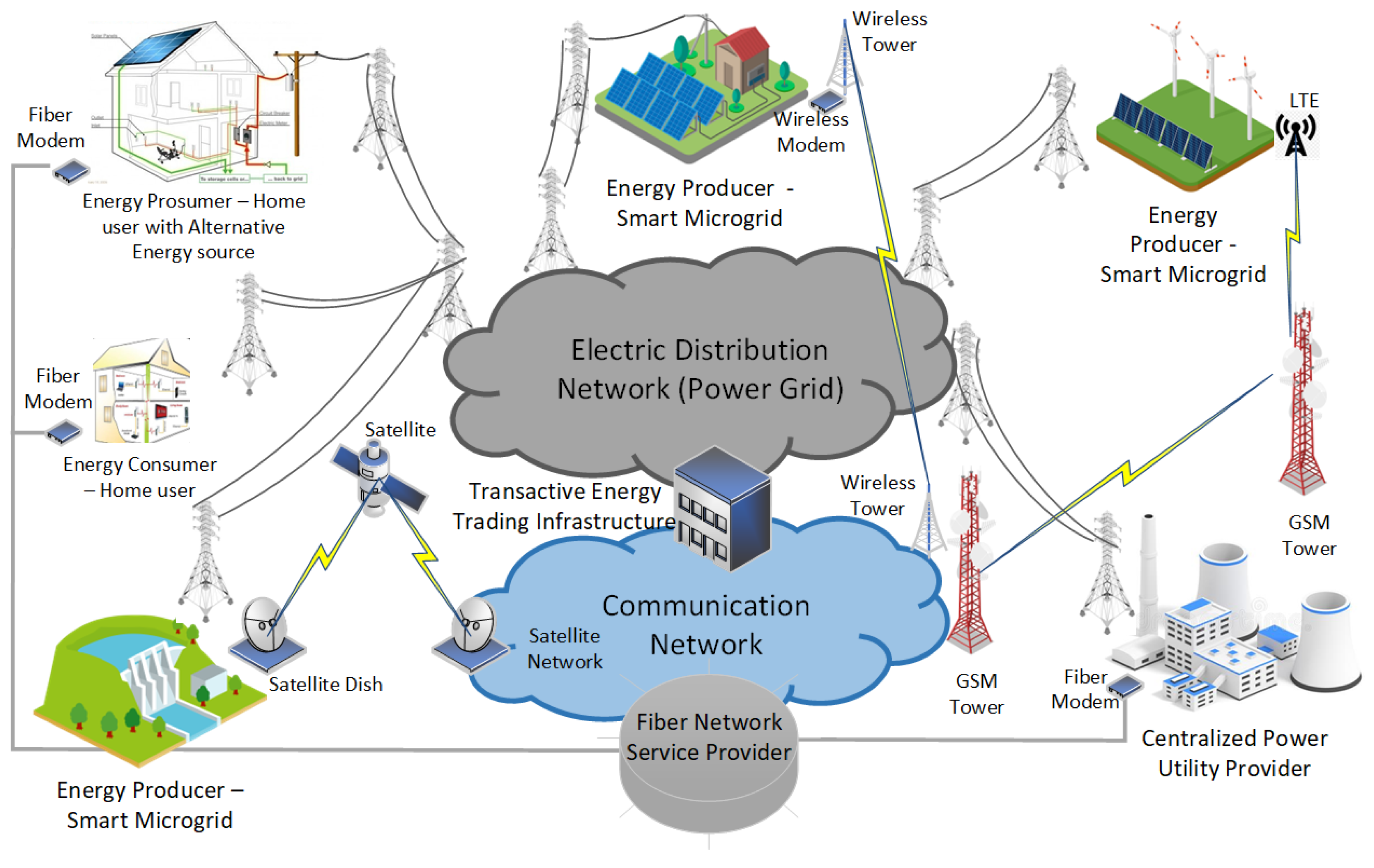
Figure 1 illustrates a basic architecture for a decentralized smart microgrid network. It shows that the electric distribution network and communication network operate in separate environments to the same endpoints: SMGs (energy producers only), prosumers and consumers.
In
Figure 1, the electric distribution network is the maximum voltage (MV) distribution network that geographically provides power to areas that are stepped down at the local substation to the user’s and prosumer’s operating voltage in the distribution level of the low voltage (LV) network. The communication network comprises various mediums, including fiber networks, GSM networks, wireless networks, and satellite networks. These networks can form part of the Internet or be private networks, providing Internet protocol (IP) connectivity for prosumer networks using Smart microgrids.
The ability of SMGs to distribute energy into the power grid and the requirement of consumers for energy from the power grid creates the opportunity for transactive energy (TE), as explained by Yin et al. [
2]. According to Kok et al. [
6], transactive energy is defined as “a set of economic and control mechanisms that allows the dynamic balance of supply and demand across the entire electrical infrastructure using value as a key operational parameter”. Bahramirad et al. [
7] provide another definition in that TE is the exchange and balance of value, or in other words, the transaction of energy. Both literature papers confirm that various participants can transact energy as a commodity. There are different types of participants in the TE processes, and Abrishambaf et al. [
8] identify them as follows:
Distributed renewable energy resources (DRER)/smart microgrids/prosumer—the entity that generates electricity from renewable resources.
Utility network—the entity that delivers the electricity to the consumers.
Consumer—the user of the delivered electricity.
Regulator—the entity providing the rules and regulations to ensure safe transactions in the marketplace.
Peer-to-peer (P2P) energy trading, which is a trading process between prosumers and consumers, is decentralized due to the independence from an intermediate medium, according to Das et al. [
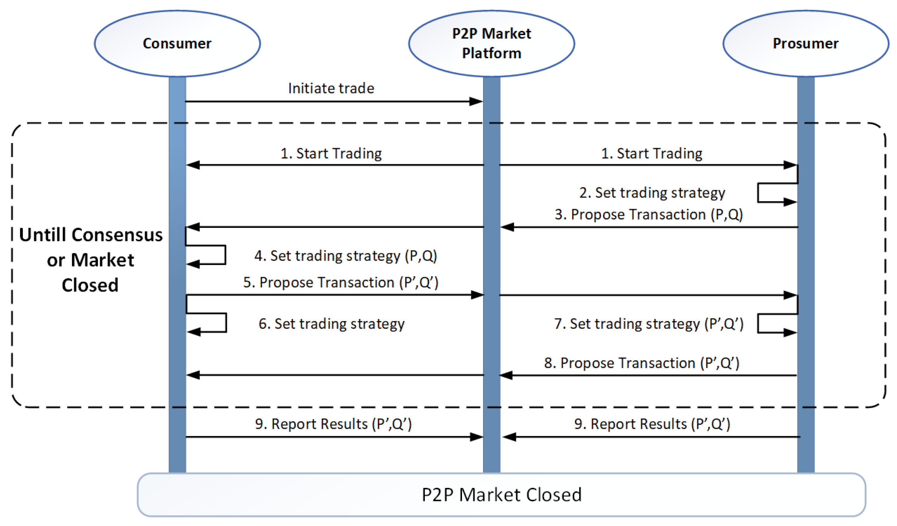
9]. They identify two pricing mechanisms that support P2P energy trading, energy pricing and network service pricing (NSP). Energy pricing is classified into two trading strategies, synchronous and asynchronous strategies. Both strategies use proposed pricing and volume as the base of the trading, denoted P and Q in the sequence diagram in
Figure 2 below.
The sequence diagram in
Figure 2 was adapted from Das et al. [
9] and it shows multiple exchanges of trading information between the prosumer, consumer, and the P2P market platform. The proposed transaction comprises the pricing P (USD/kWh) and volume Q (kWh).
In addition, Zahraoui et al. [
10] also confirm that the decentralized energy trading strategy within a local area is a modern approach. They state that it is essential to create a local energy market to support a Peer-to-peer market, community-manager-based market, and a hybrid P2P market. This decentralized approach requires new localized governance of the energy infrastructure.
Various literature documents identify the challenges that traditional IP architectures encounter. According to Sun [
11], traditional IP technology cannot support real-time business traffic on the Internet. This limitation is due to two reasons: the data path and data delivery are unreliable, and packet-switched services of the IP network are best-effort. He proposes a multiprotocol label switching (MPLS) based network with quality of service (QoS) as a solution. Typical transaction-type networks, such as financial institution networks (banking networks), use MPLS networks to establish a dynamic communication network between all the relevant nodes. Sun [
11] explains that MPLS creates a label between the layer 2 header and the layer 3 IP data header. The basic concept of MPLS is to combine the IP routing technology of the third layer with the switching technology of the second layer through a process called label switching. Unfortunately, certain communication technologies cannot identify the MPLS label and support the MPLS function. This limitation makes MPLS challenging to use as a flexible architecture.
Based on the literature study, there is a research gap regarding the need to improve the reliability, flexibility, and security of the existing IP infrastructure as applied to transactive energy in smart microgrid systems (TESMS). This requirement is due to the static nature of traditional IP infrastructure that is unable to adapt to the dynamic nature of the transactive energy process. Although software-defined networking (SDN) technology has been designed to adapt to the dynamic requirements of a Transactive Energy Network, there is a need to develop an optimized SDN network architecture that meets the reliable, flexible, and secure requirements of TESMS. In this manuscript, SDN is referred to as a technology for network management that enables dynamic, programmatically efficient network configuration of TESMS in order to improve network performance and monitoring [
12]. SDN centralizes management by abstracting the control plane from the data forwarding function in the discrete networking devices [
12].
This development has not been proposed in the existing literature. Therefore, this paper explores the development of a suitable SDN architecture for the TESMS. The following contributions are made in this paper:
Design considerations of existing SDN architecture applied to TESMS.
Development of a suitable SDN architecture for TESMS.
Simulation and analysis of the developed SDN architecture for TESMS.
Detailed performance evaluation of the developed solution.
The organization of the rest of the paper is as follows:
Section 2 provides literature research and investigation on related work.
Section 3 reviews the design considerations of SDN in view of transactive energy in SMGs.
Section 4 demonstrates the development of the SDN architecture for TESMS.
Section 5 provides the simulations and results analysis of the elements in the developed SDN architecture.
Section 6 discusses the results and limitations of each design consideration.
Section 7 concludes the paper with a summary and planned research.
2. Related Work
Ensuring suitable quality of service (QoS) for service-oriented applications (SOAs) is another challenge in traditional architectures, according to Khan et al. [
13]. Transactive energy can be classified as an SOA because it is a real-time application sensitive to packet loss. Their study confirmed the challenges that traditional IP infrastructure presented for SOAs. They focused on an SOA-based software-defined network (SDN) solution that guarantees the required end-to-end QoS by improving the control algorithm that mitigates packet loss.
Standardized routing protocols are introduced in traditional IP networks to mitigate the static configuration challenges in the traditional IP architecture. However, Fiade et al. [
14] perform a failover performance analysis between three routing protocols, RIPv2, OSPF, and EIGRP (enhanced interior gateway routing protocol). Their simulations show that the failover switching delay is significant. The delay is due to the time it takes to repopulate routing tables. For real-time applications, the delay will cause errors in the exchange of information.
Another challenge of traditional IP Networks is proprietary hardware and features. Do et al. [
15] state that existing traditional IP networks consist of multivendor legacy equipment with proprietary protocols, features, and capabilities. They have also been installed, configured, and operated statically through vendor-specific management systems. This configuration expects to adapt slowly to the new challenges required from applications such as transactive energy. Therefore, transactive energy requires a new network architecture that supports real-time adaptation and flexibility.
The increasingly complex network requirements resulted in the emerging software-defined network (SDN) to allow network administrators to manage a network through an abstract of the lower-level functionality. SDN separates the data plane and the control plane in a network. It removes the control function from the network devices and allows network operators to manage and optimize network resources from a controller. SDN thereby simplifies the remote device to a network switch.
Karakus et al. [
16] confirm this by stating that SDN architecture emerged to satisfy complex networking requirements due to the limitation of traditional networking architecture. A traditional architecture faces a complex problem when adding or removing a device from a network, confirming a flexibility limitation. Furthermore, the configuration of the devices in traditional network architecture is complex and, most of the time, proprietary to the device’s manufacturer. A typical example is the enhanced interior gateway routing protocol (EIGRP) developed by Cisco Systems, and only Cisco networking devices support this protocol. This unique function often requires a skilled and qualified individual to troubleshoot, configure or install a new device in the network. This problem suggests that the traditional network architecture faces challenges of network inflexibility and hence the need to develop a dynamic architecture.
It is important to note that an SDN architecture described by Karakus et al. [
16] can meet this requirement. An SDN architecture simplifies the programmability of the network, enabling network operators to manage and configure network elements more easily. However, the authors further state that SDN has scalability limitations due to the centralized control nature of software-defined networks.
Latif et al. [
17] identify three planes in an SDN architecture: data plane, control plane and application/management plane.
Figure 3 illustrates the layer view of the SDN architecture, indicating the applications in the management plane.
The SDN architecture in abovement
Figure 3 was adapted from Latif et al. [
17] and it uses the southbound interface (SBI) for protocols such as OpenFlow, Netconf, and SNMP to separate the control plane and data plane. It shifts the decision-making operation of the customer premises equipment (CPE) to the SDN controller. The northbound interface is the communication channel between the controller application (also referred to as SDN orchestrators) in the management plane and the controllers in the control plane. Finally, the east−west interface allows inter-controller communication for functions that include controller load balancing and network scalability.
Although SDN can meet some reliability and flexibility network requirements, it must still be optimized for the application and dynamic environment. For example, it is noteworthy to mention that SDN is not a mature solution according to Do et al. [
15]. They confirm that particular challenges remain to be addressed, specifically for SDN-enabled wireless mobile backhaul networking. The challenges they identified apply to transactive energy and include optimized SDN southbound protocols, SDN controller solutions that meet the needs of the application, specific SDN and NFV integrated solutions, backhaul infrastructure sharing, multidimensional optimization policy, path calculation and information security, to name a few.
Li et al. [
18] confirm that SDN enhances the network’s resilience. However, the network is vulnerable to cyberattacks due to the flexible network integration of the SDN nodes and universal network visibility. They further explain that the ICT community is becoming more aware of growing attacks against SDN.
Literature research found multiple examples of SDN designs in microgrid systems that focus on managing and controlling the microgrid. They prove that their SDN approach is an improvement to traditional ICT infrastructure; however, they do not consider the scalability of the SDN network, heterogeneous ICT infrastructure, or security vulnerabilities.
Earlier SDN designs in smart microgrid systems (SMGSs) explored the SDN’s advantages in managing the electrical grid conditions with a smart microgrid system. For example, Dorsch et al. [
19] explored SDN to manage transmission and distribution networks and demonstrated the enhancement of the SMGS’s resilience through SDN.
Microgrid emergency control (MEC) through active fault management (AFM) is a function that benefits from an SDN architecture. Ren et al. [
20] confirm that SDN provides continuous and reliable data transmission for detecting emergency conditions and reconnecting the microgrid to the primary grid. Wan et al. [
21] also explore SDN to ensure a highly resilient AFM. Both papers do not include security enhancements or network resilience considerations in their designs.
Another application of SDN in SMGSs is around advanced metering infrastructure (AMI), as explored by Kim et al. [
22]. They outline the advantages of an SDN architecture on applications such as security, load balancing, electrical system and network monitoring, and data routing. Akkaya et al. [
23] also confirm that SDN is a suitable solution for supervisory control and data acquisition (SCADA) and AMI in SMGSs.
Smart energy management applications in smart microgrid systems find multiple benefits with an SDN approach. Zhou et al. [
24] explore a software-defined machine-to-machine (SD-M2M) solution that provides benefits such as vendor-independent control, coordinated mobility control, fine-granularity resource allocation, and end-to-end QoS guarantee.
There are literature papers that explore network solutions for transactive energy in particular. For example, the work of Zhang et al. [
25] explores an SDN network architecture for energy internet, which is like transactive energy. Their solution confirms that SDN is a suitable architecture for energy internet. However, their study differs from this paper in that it proposes an integrated hardware solution that combines the communication network and the electrical grid network into an intelligent energy controller (IEC). Furthermore, their solution lacks network resilience, SDN scalability and security considerations for energy internet.
The work of Lu et al. [
26] developed an SDN-enabled communication network framework for energy internet. Their study confirms that energy internet (like transactive energy) experiences flexibility, reliability, and latency challenges. Their solution also proves that SDN is a suitable architecture for energy internet. However, their study only focuses on an SDN architecture in a specific, low-latency network environment. Therefore, it does not consider reliability, flexibility, or security requirements.
3. Software-Defined Network (SDN) for Transactive Energy in SMGs
An SDN Architecture is the network layout that consists of the SDN controller and the SDN nodes/devices. Karakus et al. [
16] review four main SDN architecture types: centralized controller designs, distributed controller design, hierarchical controller designs, and hybrid designs. The typical SDN network is a centralized controller design that consists of a single control and data plane, whereby all the SDN devices connect to a single SDN controller.
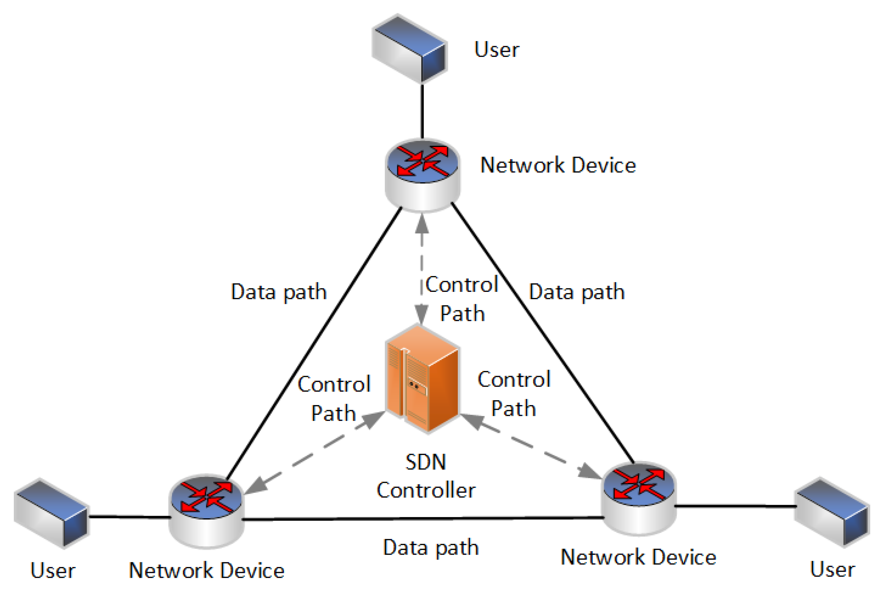
Figure 4 below from Karakus et al. [
16] represents this configuration.
Figure 4 was adapted from Karakus et al. [
16], and it shows that each network device connects to the SDN controller in a star network configuration for the control paths. The controller and the application core network reside in the same physical environment in a real-world SDN example. The data paths from the users to the Application core are then also in a star configuration, which means that the control path and data path exist on the same network infrastructure. For example, financial institutions (banks) use a shared database infrastructure that enables their branches or ATMs to access account and customer information for financial services and banking processes. The SDN controller is located at the exact location of the database infrastructure. Therefore, all the remotes require access to the same Intranet for control and data functions. There is no need for site-to-site communication because neither the branches nor the ATMs need information from other branches or ATMs. This functional requirement means that the centralized SDN architecture is preferred for a financial institution. However, as Karakus et al. [
16] explain, a centralized SDN architecture cannot efficiently handle large-scale networks, and a hierarchical controller design needs to be considered.
Another example of a centralized SDN network is electrical network management functions such as advance metering infrastructure (AMI) and active fault management (AFM), which require a centralized SDN architecture because information on AMI and AFM is stored in a centralized network environment. There is no requirement for site-to-site communication; the remote site only needs a communication channel to the database infrastructure to send metering information and fault status information. This function means the centralized SDN architecture is optimal for electrical network management functions.
However, centralized SDN architecture networks can face particular challenges and limitations. Authors Wang et al. [
27] found that an SDN with a single SDN controller may experience scalability, data utilization bottleneck and single-point-of-failure challenges when presented with increasing network size. Although a distributed controller system may have advantages that solve these challenges, they also identified the following challenges that the distributed controller system needs to address,
Reliability in SDN ensures that the data path between end nodes is always available. While scalability is a significant limitation [
16], a balance between the best route and the network capability is required to achieve optimal reliability. The data path relies on the availability of the network, and the fewer dependencies there are between SDN nodes, the more reliable the data path becomes. Research on latency-oriented controller placement to optimize the delay between SDN switches and SDN controllers for the shortest path assumes the network is reliable. Fan et al. [
28] reveal that research does not consider network failures in their design. However, their research showed that placing a controller closer to the SDN switches provided an optimized shortest path between the SDN controller and the SDN switches. A network consists of multiple network elements and connections that can influence the reliability and availability of the data path, confirming the importance of the SDN controller placement. To improve the reliability of the SDN architecture, a decentralized SDN controller placement needs to be considered.
Another consideration to improve the availability of a data path is to limit the number of point-of-failures (POF) or the number of circuits between SDN nodes. Verma et al. [
29] state that the expression for reliability (
R(
t)) is a function of the failure rate (
λ(
t)) over time. The expression is independent of the law of variation of failure rate, i.e., constant failure rate. Therefore, a network’s availability is the product of the availability of all the POFs in the network. The availability is, therefore, inversely proportionate to the number of POFs. As the number of POFs decreases, the availability increases. When availability increases, then the reliability improves. An SDN node in an SDN network may have multiple connections to the network, and redundancy is another method to reduce the failure rate of the data path that will improve the reliability of the data path. By dynamically changing the data path due to a link failure at the SDN node, the downtime of the data path reduces, which in turn increases the availability of the data path. A redundant path configuration in the SDN architecture, therefore, improves the reliability of the data path.
Jin et al. [
30] simulate FAVE, a bandwidth-aware and seamless failover mechanism for SDN network virtualization. They can successfully simulate a data transfer between two tenants with two links (tenant routes (TR)), during which the active TR ‘fails’ and the second TR seamlessly continues with the data transfer.
Flexibility in SDN is the ability to adapt to different types of network technologies and network conditions. For example, Galan-Jimenez [
31] optimizes the control of a hybrid IP/SDN network through a generic algorithm (GA) that effectively conserves energy consumption of the different nodes in the network. The algorithm considers specific parameters, and Galan-Jimenez identified two strategies, the most noncontrolled link first (MNL) and least noncontrolled link first (LNL). Both strategies show how a control algorithm can improve network flexibility by adapting to controllable and noncontrollable network elements.
Another approach to improve flexibility is to create a mesh network of nodes that enables multiple paths between two nodes, especially in a mesh network architecture. Determining the shortest path between any two nodes is a well-known problem in operational research, according to Aini et al. [
32]. A typical real-world example of the shortest path problem is determining the quickest route through a city or country. Well-known online and mobile map applications solve the problem through shortest-path algorithms. Aini et al. [
32] review the Floyd−Warshall algorithm in a mesh network to calculate both the shortest cost and shortest route between pairs of nodes. The ability to adapt the routing algorithm in an SDN increases the flexibility of the network by providing the optimal communication path. Al-Sadi et al. [
33] explain that this can be achieved by changing the location, the frequency, and the way of the routing algorithm.
The advantage of SDN that simplifies the Integration of SDN nodes into an SDN network is mainly due to SDN’s visually open network architecture, which is a security concern in a public network environment. The traditional IP network architecture utilizes several security protocols that include VPN (virtual private network), internet protocol security (iPsec), generic routing encapsulation (GRE), and cloud-based services such as FWaaS (firewall-as-a-service). These security protocols are not limited to specific network architectures and can be used in SDN architectures. Furthermore, these security protocols are static by nature.
Data encryption is one of many methods to provide network security. Li et al. [
34] provide a practical example of how SDN can support real-time reconfiguration of the control plane to isolate compromised devices during cyber-attacks. Their design monitors the network with the expected traffic patterns. When their system detects a traffic pattern that differs from the expected model, their algorithm removes the flow entry of the affected element. Jin et al. [
35] confirm that the dynamic programmability in SDN guarantees timely detection and rapid response to the impact of malicious attacks on the Smart Microgrid System. Their design follows a three-step approach:
Step 1: Detect and isolate the compromised element.
Step 2: Eliminate traffic from the malicious source closer to the source, and
Step 3: Ensure connectivity of sensors to the network.
Encryption on the SDN network’s control and data path improves the SDN solution’s security for TESMS.
4. SDN Architecture Development for a Transactive Energy Network
SDN is a standardized network architecture. A typical SDN architecture comprises a single controller and a network of SDN CPEs that are geographically distributed over a large area at a national level. Each SDN CPE is located at a consumer of prosumer premises connected to nationwide network infrastructure or the Internet. Each CPE provides connectivity to its hosts. The network represents the Internet Infrastructure consisting of multiple Internet service providers (ISPs) and interconnected nodes that form the SDN network’s data plane. The connection from the SDN switch to the network is not vendor or technology specific and can include technologies such as GSM, wireless, fiber, or satellite connection.
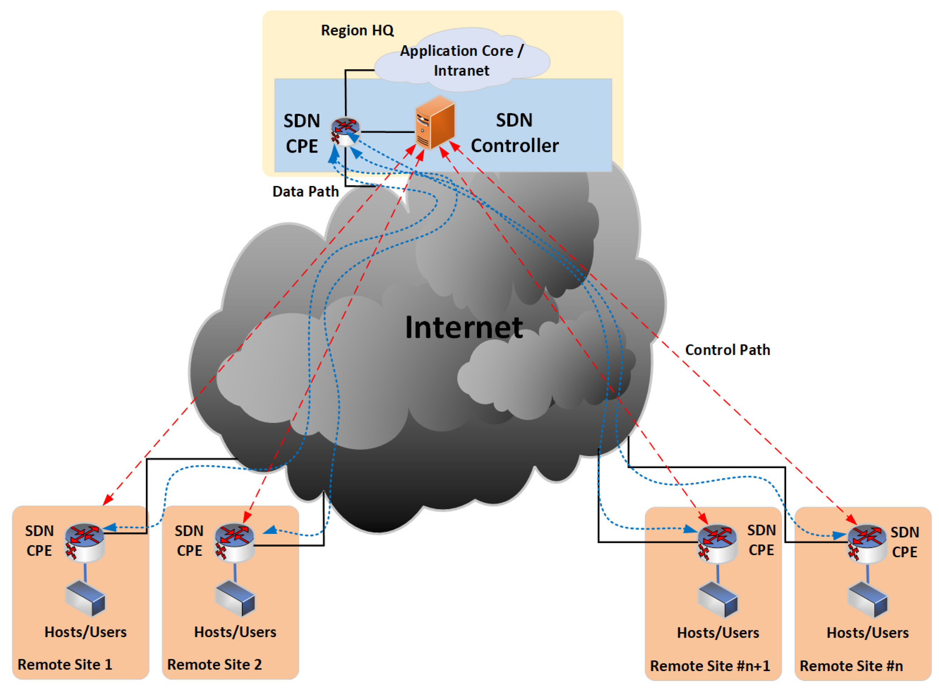
Figure 5 below is a diagram of a typical SDN network that can support TESMS.
Figure 5 illustrates a typical SDN architecture based on the centralized controller design by Karakus et al. [
16]. In a star network configuration, the controller is located at the application core, meaning that each SDN CPE’s data path (blue line in
Figure 5) and control path (red line in
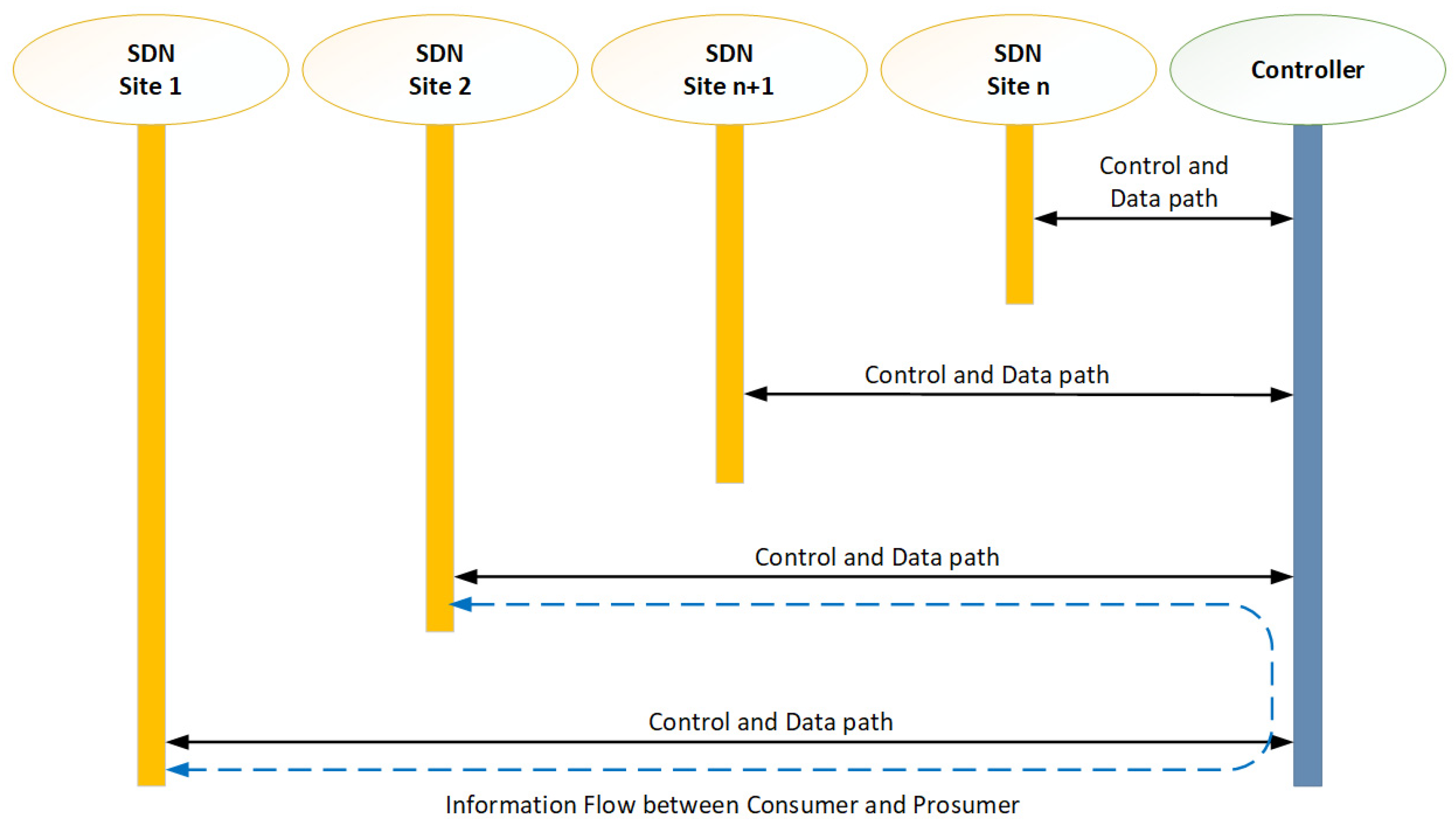
Figure 5) follow the same physical communication channel. The consumers and prosumers of the transactive energy network are geographically distributed, which means that the connections between SDN switches operate on a geographically extensive network such as the Internet. The information flow between prosumer and consumer flows through the controller, confirming the extent to which the information is flowing in a start topology.
Figure 6 shows the information flow between a consumer and prosumer. A single controller hosted in a centralized location controls all the SDN switches to establish the control path of the SDN architecture. Each SDN switch has a point-to-point connection to the SDN CPE at HQ to complete the data path of the SDN architecture.
For transactive energy, most energy trading in the TE process occurs between the SMG, the prosumer, and the consumer, which is site-to-site communication. In addition, the SMG communicates with the regulatory authority for the economic and regulatory validation of the TE process.
Fan et al. [
28] state that a centralized SDN architecture design faces scalability and reliability challenges. Access bandwidth for control messages (control traffic), controller memory, and processor constraints limit large-scale networks’ scalability. Therefore, the increase in network size increases the access bandwidth and controller resource utilization, influencing network reliability due to the potential risk of failure.
To optimize the SDN architecture for TESMS, the final design needs to consider the following design considerations,
- i.
Improved reliability in the SDN architecture
Decentralized controller distribution in the regions optimizes the control traffic between the controller and the nodes. It minimizes the usage and utilization at each controller and the number of POFs. It further improves the end-to-end link availability based on the reduced network elements between the nodes. This approach will enhance the reliability of the network.
Redundant link configuration at each node improves availability by reducing the failure probability of the communication link. Improving the availability improves the reliability of the network.
- ii.
Improved flexibility in the SDN architecture
A mesh topology enables dynamic communication between SDN nodes to improve network flexibility. This function enables the network to establish multiple routes between SDN nodes. A controller code is then required to determine the optimal data path between SDN nodes dynamically. Adapting to a dynamic environment and determining the optimal data path improve the architecture’s flexibility.
- iii.
Improved security in the SDN architecture
The universal network visibility of an SDN architecture is a security vulnerability open for intrusion and malicious activity. An encrypted data path will hide the information to improve the security of the SDN architecture.
It is worth mentioning that a centralized SDN design has two design concerns,
Control traffic at the SDN controller for an extensive, geographically distributed network can be high compared to the data traffic of the TESMS application.
The number of network nodes between SDN nodes at the controller and the remote site can influence the reliability of the data path from the remote sites.
SDN nodes send information regarding hosts (users) to the controller. The controller then sends control information regarding the data flow for the host to the SDN Node. Therefore, the control traffic will also increase with increased hosts or users on the SDN network. An SDN network’s usage and utilization performance is linearly related to the number of nodes. Therefore, decentralizing the network by n-times controllers will reduce the usage and utilization at each controller by factor n.
A decentralized controller placement approach also reduces the number of network nodes between the SDN controller and the SDN node. From literature reviews [
36], the Internet infrastructure consists of multiple network elements with diverse routes and technology types.
Decentralizing the SDN network will reduce the number of circuits between the nodes by reducing the number of failure points in the system that will influence the network’s reliability. The availability of each circuit represents the failure probability of each circuit. The availability parameter of a link in % represents the uptime. As previously mentioned, Verma et al. [
29] stated that the reliability (
R(
t)) of a single device or link could be expressed as a function of the failure rate (
λ(
t)) over time,
If the failure rate
λ is constant, then the expression for availability reduces to,
The total link availability is the sum of all the circuit failures connected in series. This result is because failures do not occur simultaneously. Over time
t, the total failures accumulate. The failure rates of each circuit are added together to calculate the total failure rate.
The Equation can be written as follows if all the circuits have the same failure rate.
However, the failure rate
λ is the difference between the total time (
t) = 100% and availability
A. Therefore,
λ can be replaced by (1 −
A) to provide the total availability,
As the number of circuits increases, the total link availability reduces. Decentralizing the SDN network and placing controllers per region can improve link availability. From Equation (5), the total link availability is calculated by using the number of circuits, each with the same availability parameter. For the reduction in the number of circuits (
x) from the initial number of circuits (
n) to the reduced number of circuits (
na), the availability improvement (
Ai) is the difference between the availability after the reduction (
) and the availability before the reduction (
). The improvement can therefore be calculated as follows,
where,
For redundant links from the same SDN node, the total link availability is a product of all the circuit failures that are connected in parallel. This result is because the failures of all the circuits do not occur simultaneously. The failure rate of each circuit is multiplied by each other. A redundant configuration only requires two links,
x and
y,·
And so, the total link availability is expressed as follows,
For time (
t) = 100%, the failure rate
λx and
λy will be the difference between the availability
Ax and
Ay,
With low-availability links, a redundant configuration can provide a significant improvement in the total availability of the node,
An SDN network with a mesh topology requires a specific control algorithm approach. A controller’s default flow decision procedure in an SDN network is based on the principle that there is a single link between the nodes and core node, i.e., only one path from one host (application or user connected to the SDN node) to another host. A mesh topology allows multiple paths between hosts, and the controller needs to determine the best or shortest path between hosts.
The Floyd−Warshall algorithm is the best and most famous algorithm to find the shortest path between every node because it is effective and accurate. For the SDN controller in a TESMS network, the following steps in
Table 1 are used in an algorithm that is based on the Floyd−Warshall algorithm.
Literature research found multiple methods to improve security, including cyber-attack mitigation techniques, application-filtered flow control, and data encryption. According to Hauser et al. [
37], encrypting the data packet is one of the most common and proven methods to secure data and ensure integrity. A virtual private network (VPN) is a secure method to encrypt the data between nodes using IPsec.
The design considerations showed that reliability, flexibility, and security could be improved. By taking each design consideration into account for an SDN design for TESMS, the following steps in the design were followed:
Decentralized controller placement by placing an SDN controller in each region. The number of network nodes between the hosts reduces, so the number of potential network failures reduces. The usage and utilization at each controller are limited to the number of nodes in the regional network, improving the resource allocation in the SDN controller.
A redundant link configuration at each link improves the availability of each SDN node. Each node will have two links to the Internet, using any combination of media and technologies available. This list includes GSM, fiber, wireless, and satellite.
A mesh configuration that allows site-to-site connectivity. Site-to-site communication reduces the number of network nodes between SDN nodes, improving the SDN architecture’s availability and reliability.
A VPN connection between SDN nodes improves the security of the SDN architecture. Encrypting the data protects architectural integrity.
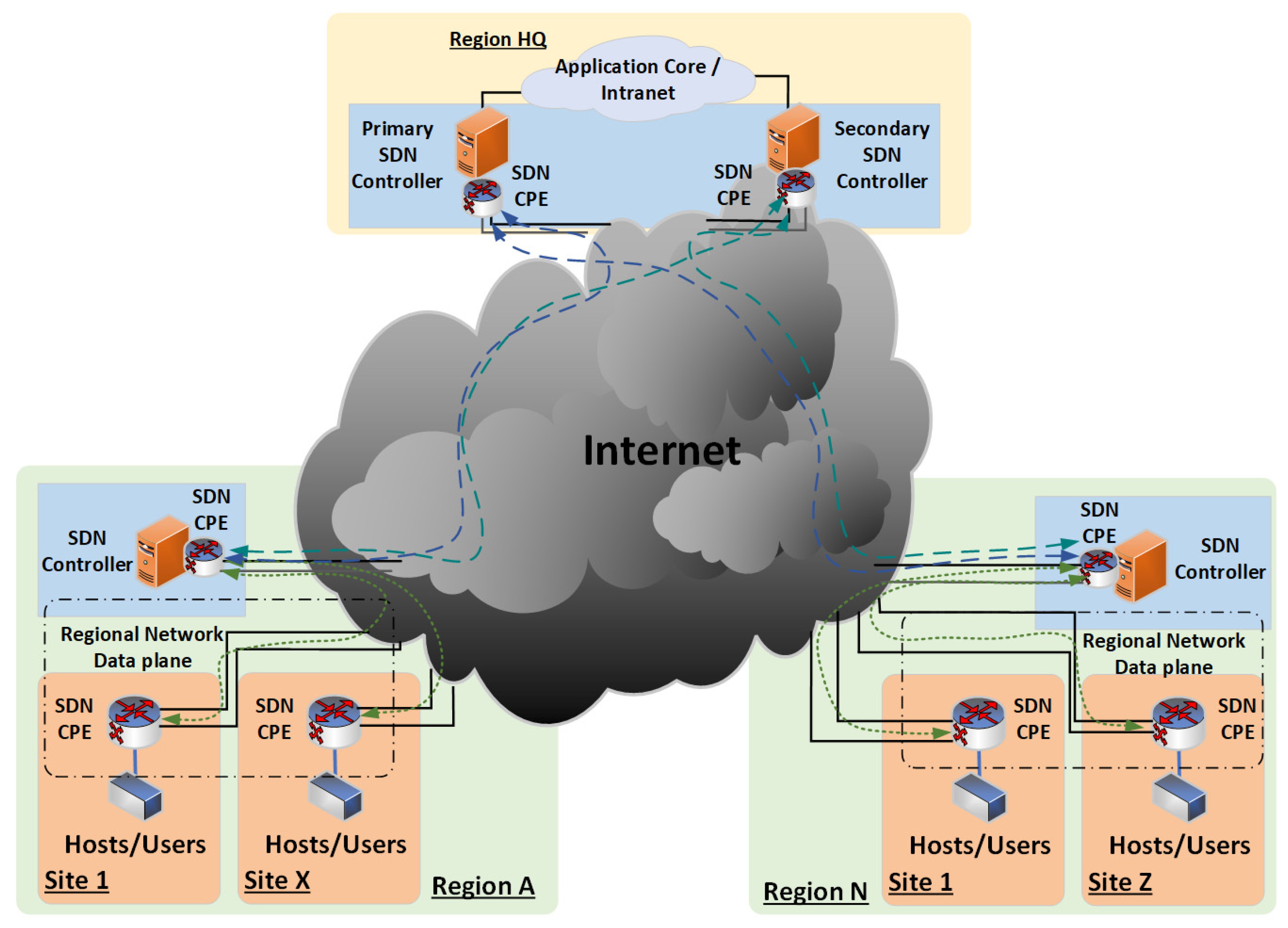
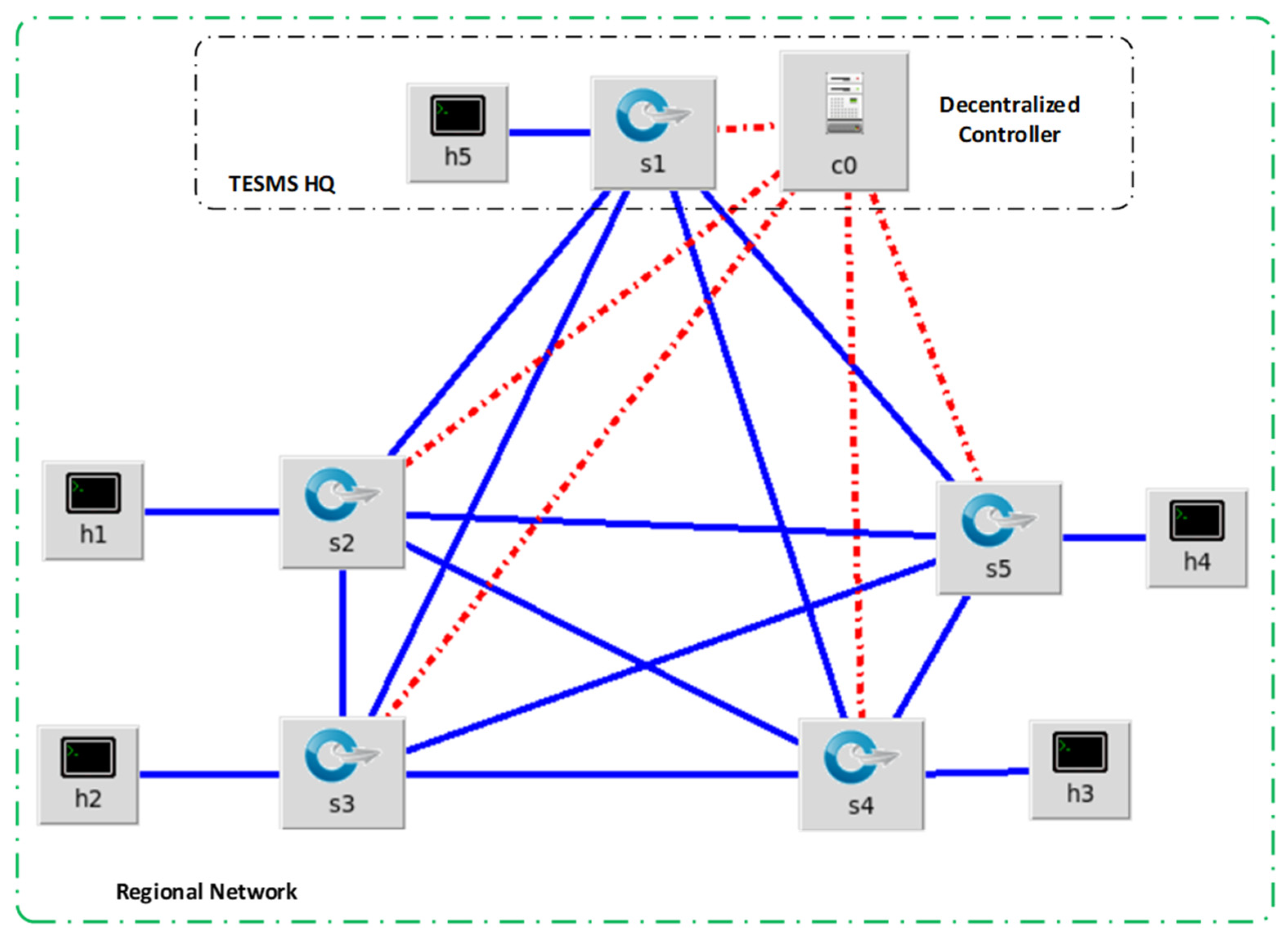
Figure 7 below illustrates the decentralized mesh SDN architecture.
In
Figure 7, each design consideration is included.
Each region has its designated controller that allows direct data flow between participants, decentralizing the SDN controller and allowing site-to-site communication for a mesh network configuration.
Each remote site has two network connections to the Internet for redundant connectivity from each SDN node, adding redundancy to each remote site.
Each controller also connects to the regional HQ for regulatory data flow and TE transaction updates to the regulator database.
The region definition is not limited to geographical or political definitions and can also include local municipalities and private gated communities or complex estates.
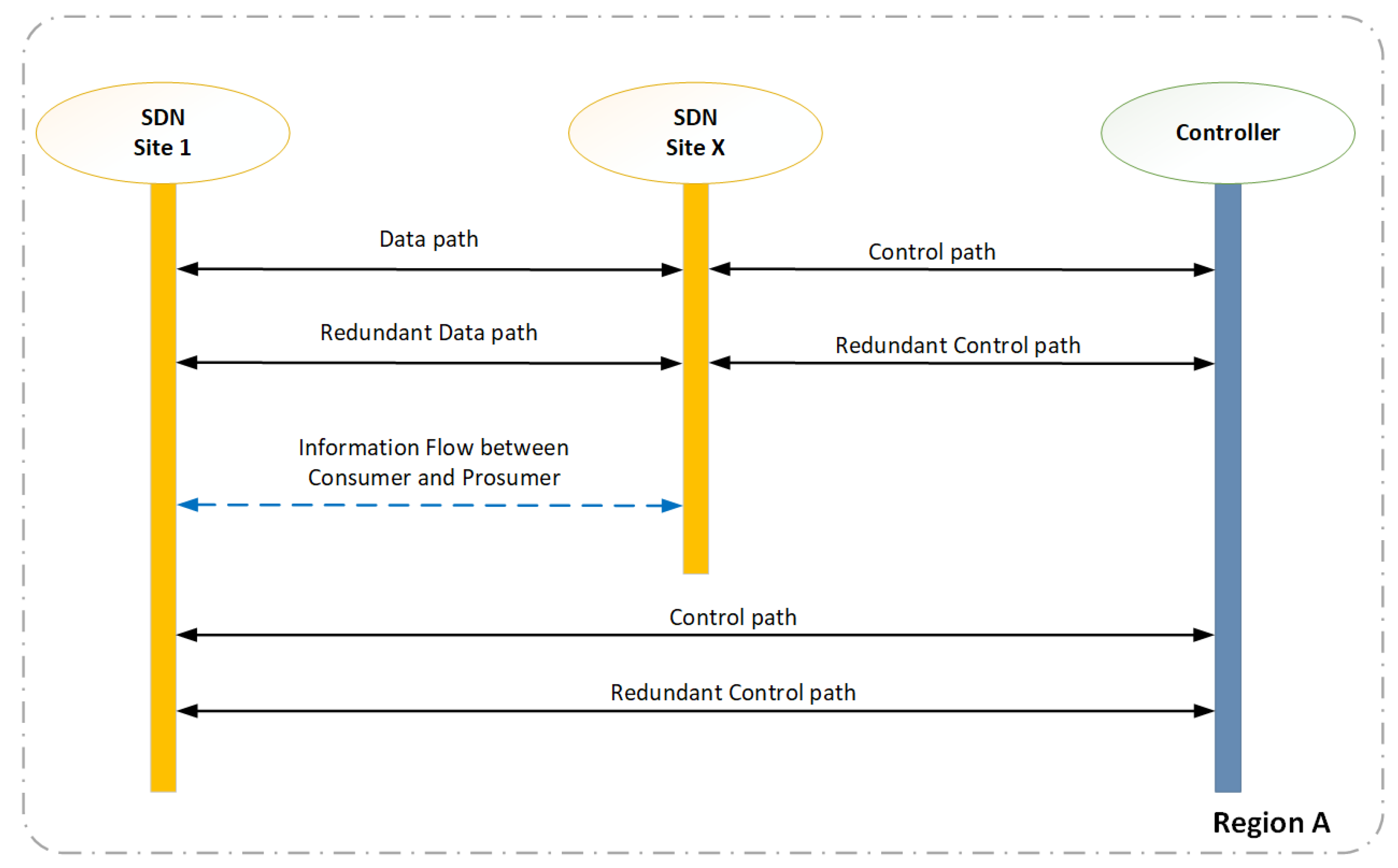
The information flow between the consumer and prosumer is now directly between the SDN nodes.
Figure 8 shows the control path and data paths are logically separated and that the consumer and prosumer can establish a direct path for the information flow during the transaction of energy.
The inclusion of the design considerations into the proposed SDN architecture will likely be an improvement for TESMS.
5. Simulations and Results
Each design consideration of the SDN design is simulated using a Mininet SDN network emulator and Anylogic system modeling software, and the results are then analyzed. The typical SDN Architecture is simulated first to provide a reference. Whereafter the improved design element is simulated. The focus of the design is to improve the reliability and flexibility of the SDN architecture, and the following areas of focus are evaluated in this chapter,
Decentralized SDN architecture is evaluated through availability and reliability simulations.
Redundant SDN architecture is evaluated through failover simulations.
A Mesh Topology Simulation is evaluated for improved flexibility in the SDN architecture.
IPsec encryption is evaluated for improved security in the SDN architecture.
The proposed design further follows the recommendation from Zahraoui et al. [
10] whereby the governance of the energy infrastructure is localized by placing the P2P market platform governance at the location of the controller. The P2P market platform facilitates the trading negotiations between the consumer and prosumer.
Finally, the proposed design is discussed and reviewed in an applied practical scenario.
5.1. Decentralized SDN Controller Simulation
The first simulations of the decentralized SDN architecture are performed with the following objectives.
Availability simulation to analyze the data path availability improvement of the decentralized controller distribution and the redundant link configuration.
Redundant link simulation to analyze the data path availability improvement of the TESMS SDN architecture.
To simulate the TE process, the simulations use the ICMP protocol (ICMP request and ICMP reply) that represents the proposed transaction, which includes the proposed price in ZAR/kWh and volume in kWh, between the hosts (prosumer, consumer, or P2P energy market). Packet loss represents the failed transactions in the TE process. Although a failed transaction will automatically be restarted, the possibility of a price change in the next attempt exists.
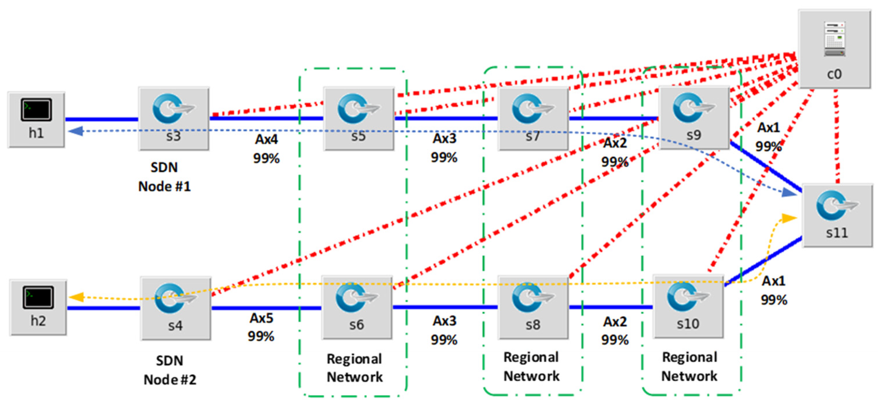
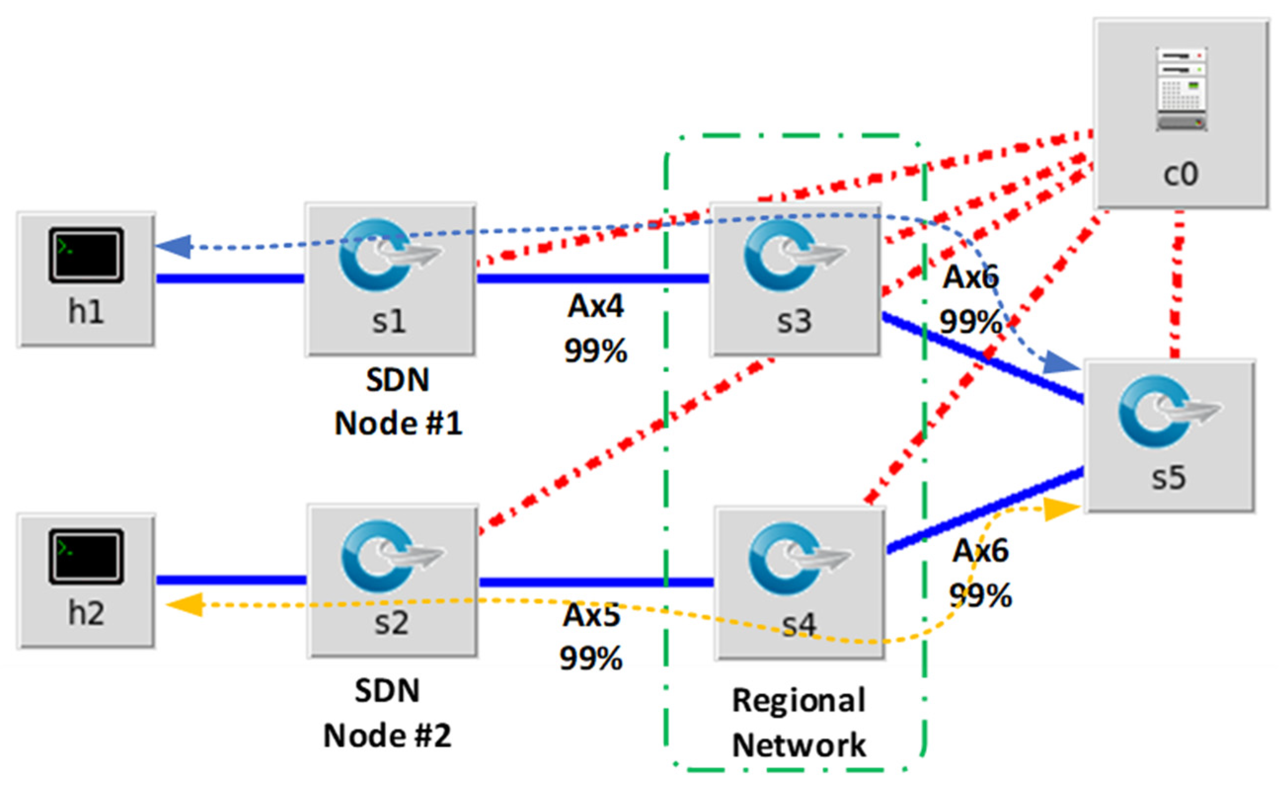
Figure 9 is the simulation diagram representing the typical centralized SDN architecture through various interconnected networks on the Internet. The Mininet simulator has a limitation regarding the packet loss definition of each link. It must be a base 10 integer, i.e., the smallest packet loss % that can be configured for each link is 1%. In one direction of the data path between the hosts, there are 8 links, each with 1% packet loss. For the ICMP ping test (ICMP request and ICMP reply), the return will traverse through the same eight links. This data path is represented in the bidirectional blue and yellow line in
Figure 9. The expected packet loss for the ping test through the 16 links is,
Figure 9.
Simulation diagram of a typical centralized SDN architecture.
Figure 9.
Simulation diagram of a typical centralized SDN architecture.
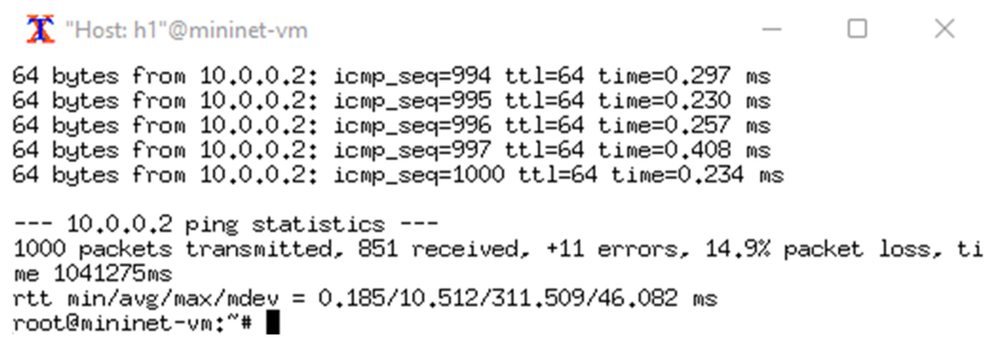
An extended simulation was initiated using a continuous ICMP test between the hosts,
Figure 10 shows that the packet loss during the typical centralized SDN architecture simulation is 14.9%. This means the data path availability of the simulated network is 85.1%.
The number of circuits between hosts is reduced for the decentralized SDN simulation.
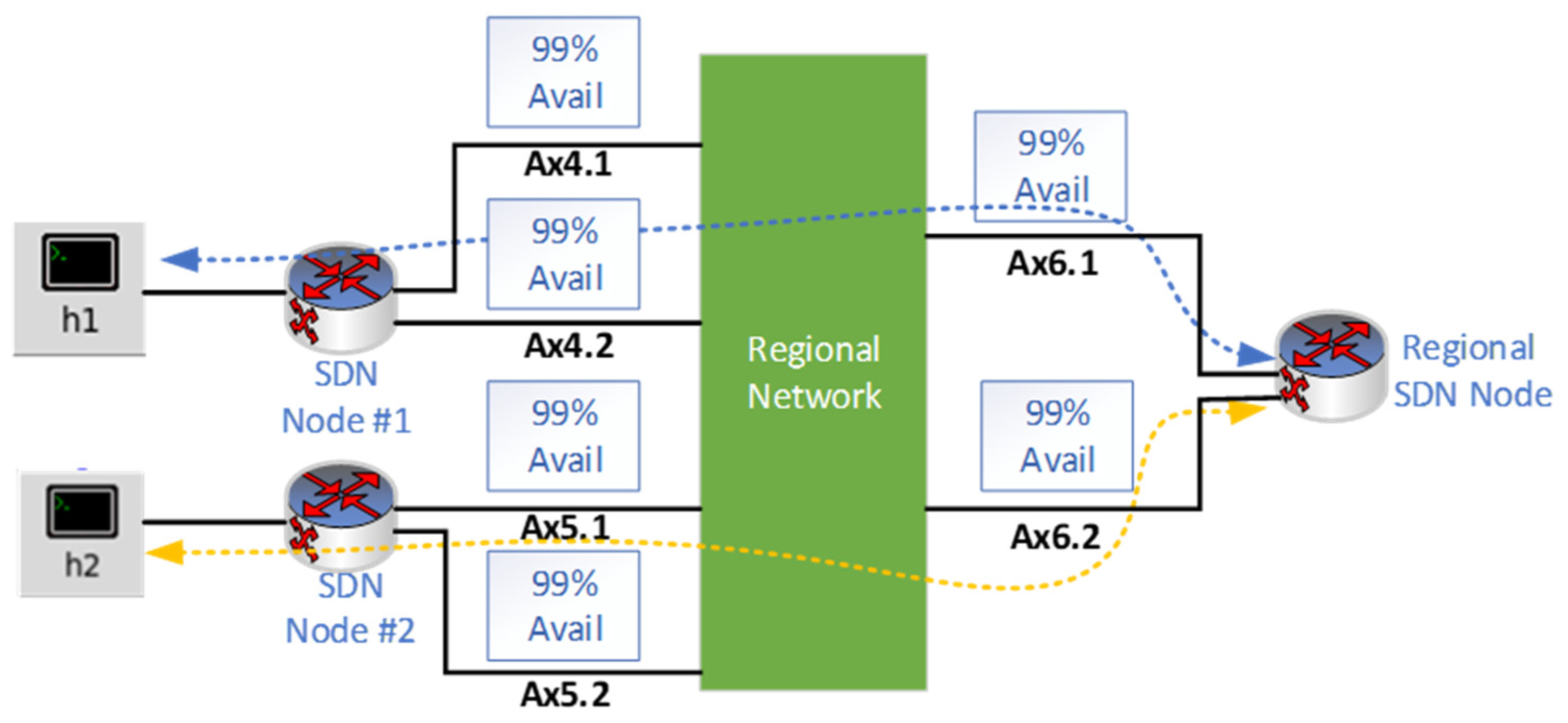
Figure 11 below shows the diagram of the simulation.
Figure 11 is the simulation diagram that represents the optimized decentralized SDN architecture. The same 1% packet loss parameter is configured on each link. The expected packet loss for the ping test through the 16 links is:
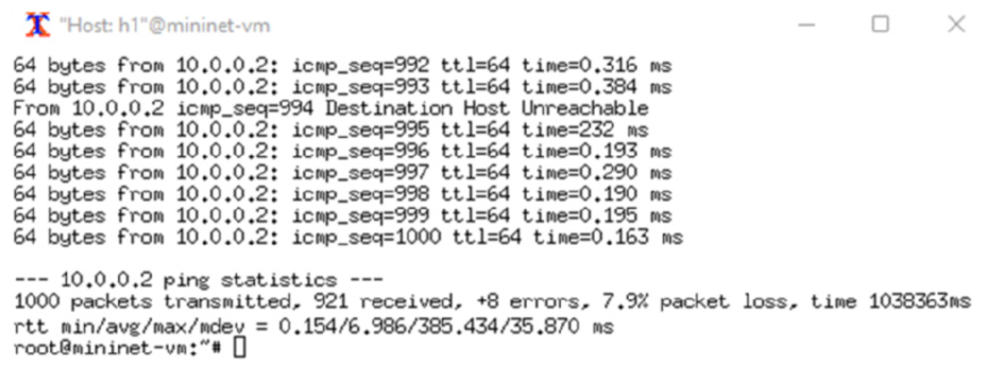
Figure 12 shows that the packet loss during this simulation is 7.9%, which means the data path availability of the simulated network is 92.1%.
The decentralized controller placement during the simulation increased the total data path availability by 7.0%. By using Equation (8), the calculated improvement is 7.1%. For the TE process, this improvement represents an improvement of 7% in successful transactions between the various hosts.
5.2. Redundant Link Configuration Simulation
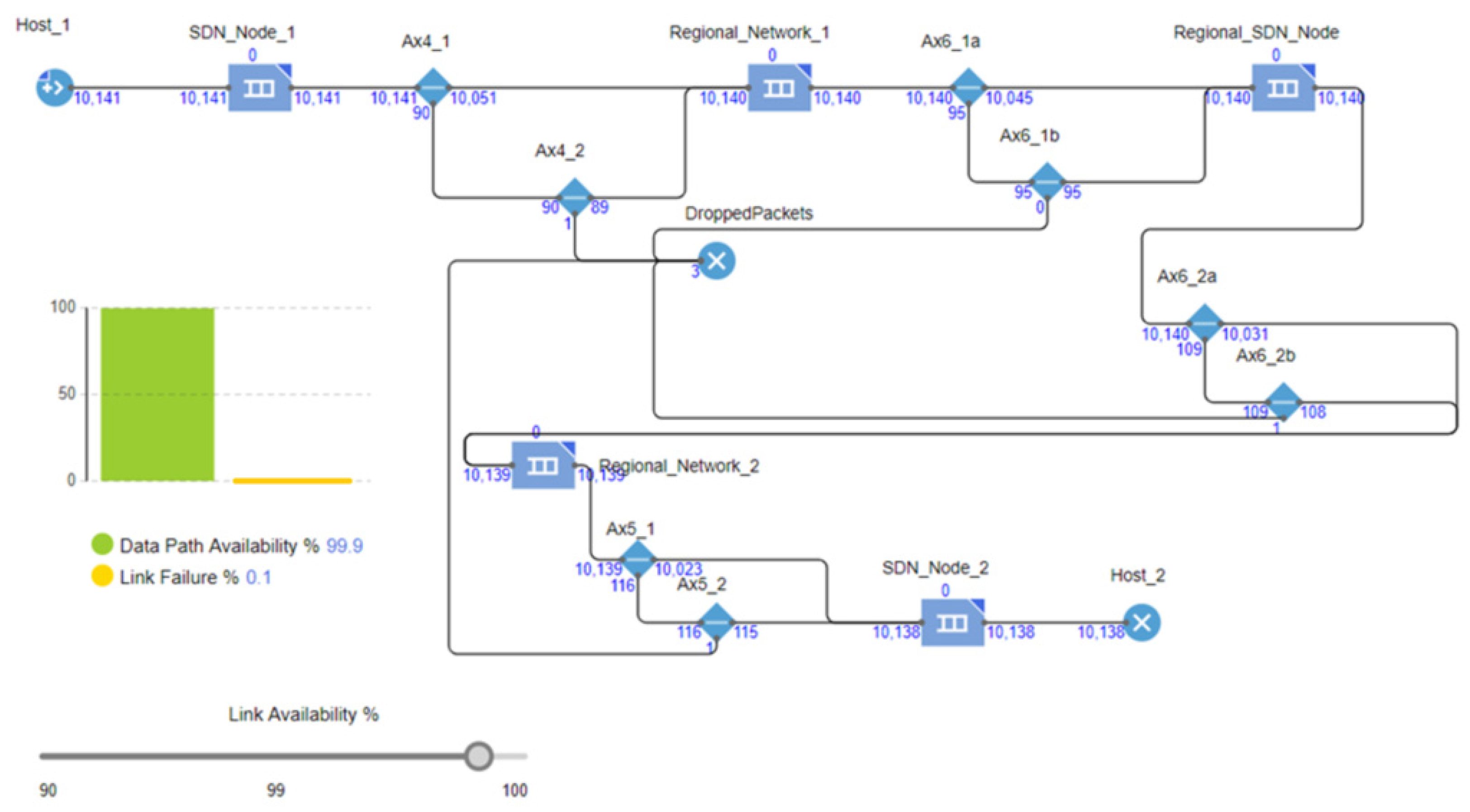
The objective of the redundant link configuration simulation is to improve the reliability of the decentralized controller configuration. For the redundant path simulation, AnyLogic system modeling software was used as it allows the simulation of event-based conditions such as redundancy and random link failures. To simulate the TE process, this simulation uses a source block and sink block to simulate the information flow of packets between the hosts. The relationship between sent and received packets determines the link availability between the hosts.
The figure below shows the diagram of the simulation.
Figure 13 shows that each SDN node is configured with a redundant link. Calculations indicate that the 99% availability per link provides 99.99% redundancy availability per data path.
Redundancy availability = = 99.99%
Data Pata path availability = = 99.92%
Link Failure rate = 1 − Data Pata path availability = 0.08%
Packets were sent from Host 1 to Host 2, simulating a ping test per the decentralized simulation. The simulation shows that the packet loss is 0.1%. An event-based simulation was setup and initiated on AnyLogic System modelling software.
Figure 14 shows that the improved result is a significant improvement compared to the single link simulation results of 7.9%, confirming that a redundant link configuration can significantly improve the SDN architecture’s reliability. For the TE process, this improvement represents an improvement of 7.9% in successful transactions between the various hosts.
5.3. Mesh Topology Simulation
The mesh topology simulation for site-to-site communication with automated failover uses the TESMS control algorithm and was derived from the POX controller Python code. The objective of the mesh network simulation is to improve the flexibility of the TESMS SDN architecture.
Figure 15 shows the simulation configuration. However, two additional SDN nodes were added for the mesh topology simulations to increase the multipath calculations. To simulate the TE process, the simulations use the ICMP protocol to simulate bidirectional information flow between the hosts.
The controller can adapt to the link failure and recalculate the shortest path between nodes.
In the simulation, the link between switch 2 and switch 4 is shut down and the controller can determine a new shortest path between host 1 and host 3 with 3 hops between the 2 hosts.
Figure 16 shows the messages from the controller during the link failure. The automated failover process is completed in 8 s, enabling the energy transaction to continue. A static SDN configuration would not be able to recalculate the data path between the two hosts, and the data path between the hosts would have been down until the link was restored. This result means that the automated failover configuration improves the flexibility of the SDN architecture by adapting to a changing environment.
5.4. IPsec Encryption Simulation
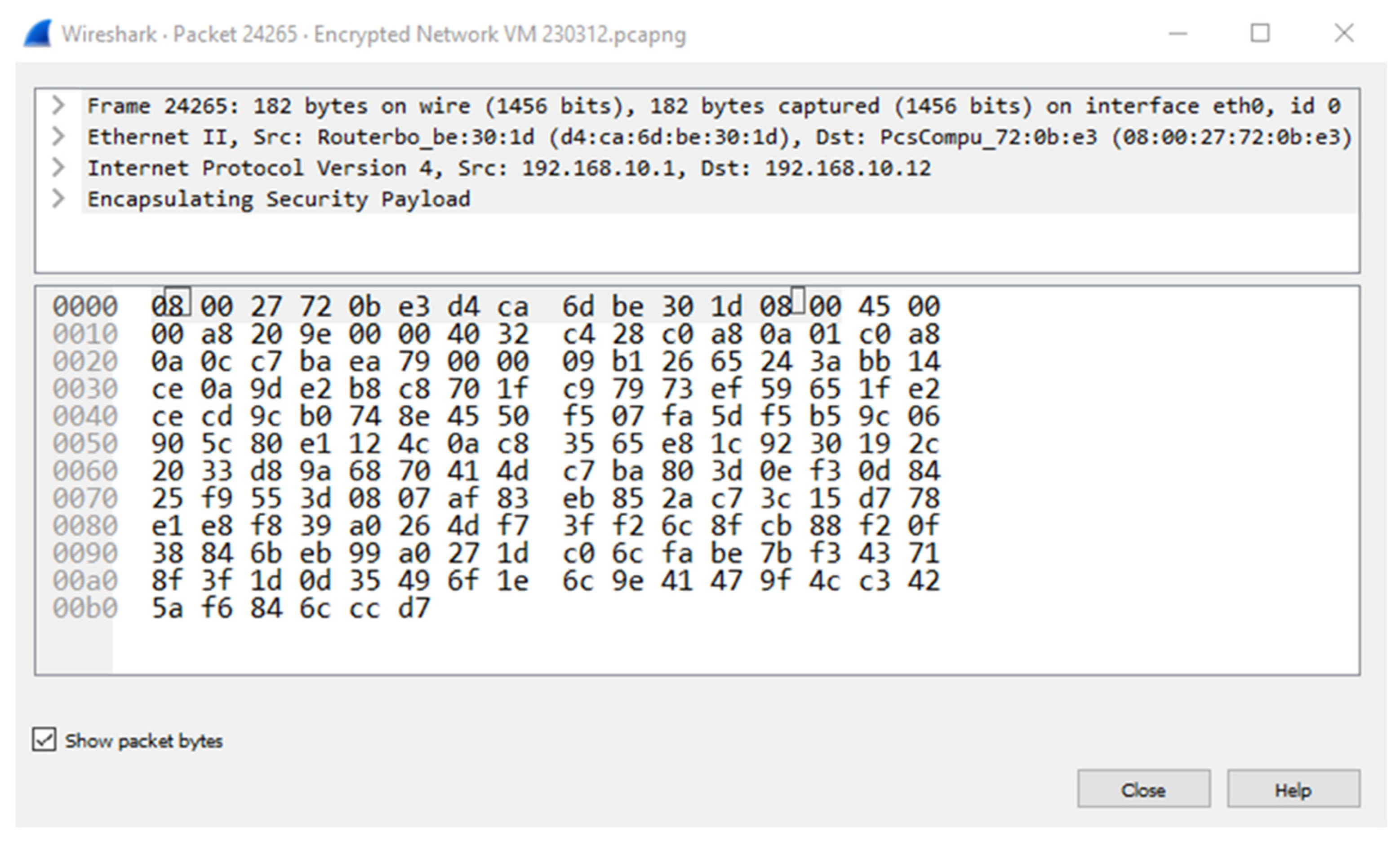
There is a security vulnerability in the SDN architecture due to the universal network visibility over public networks such as the Internet. In addition, IPsec encryption hides all the information in an encrypted packet, making it extremely difficult to use.
An IPsec tunnel between the simulation router and the Mininet network emulator is used for the security simulation. The VPN tunnel is established from the network emulator VM as the VPN client, and the simulator router as the VPN. A keyed hash algorithm called HMAC SHA1 is used to configure the IPsec tunnel in the simulation.
Packet captures are performed using the Wireshark packet analysis tool at both the network and SDN controller emulators. The objective of the simulation is to show the comparison of the nonencrypted information flow at the controller emulator to the encrypted information flow at the network emulator.
A nonencrypted packet shows the original IP packet header and data, which includes the source and destination IP address of the controller and SDN node, SDN protocol, SDN source and destination port, and the raw data.
Figure 17 shows an encrypted packet that shows the IP packet header and data. However, the encrypted IP packet’s header is the VPN tunnel information. The data in the packet is the original IP packet that is encapsulated and encrypted. Therefore, the original IP packet is not visible to the network nodes between the IPsec tunnel endpoints.
The IPsec encryption improves the security of the SDN architecture over a public wide area network (WAN). Each SDN node needs to establish an IPsec tunnel to each other to ensure the security of the SDN architecture.
5.5. Application of Developed SDN Architecture to South African Public Electricity Provider as a Case Study
Telkom is a South African wired and wireless telecommunications provider with nationwide network coverage [
38].
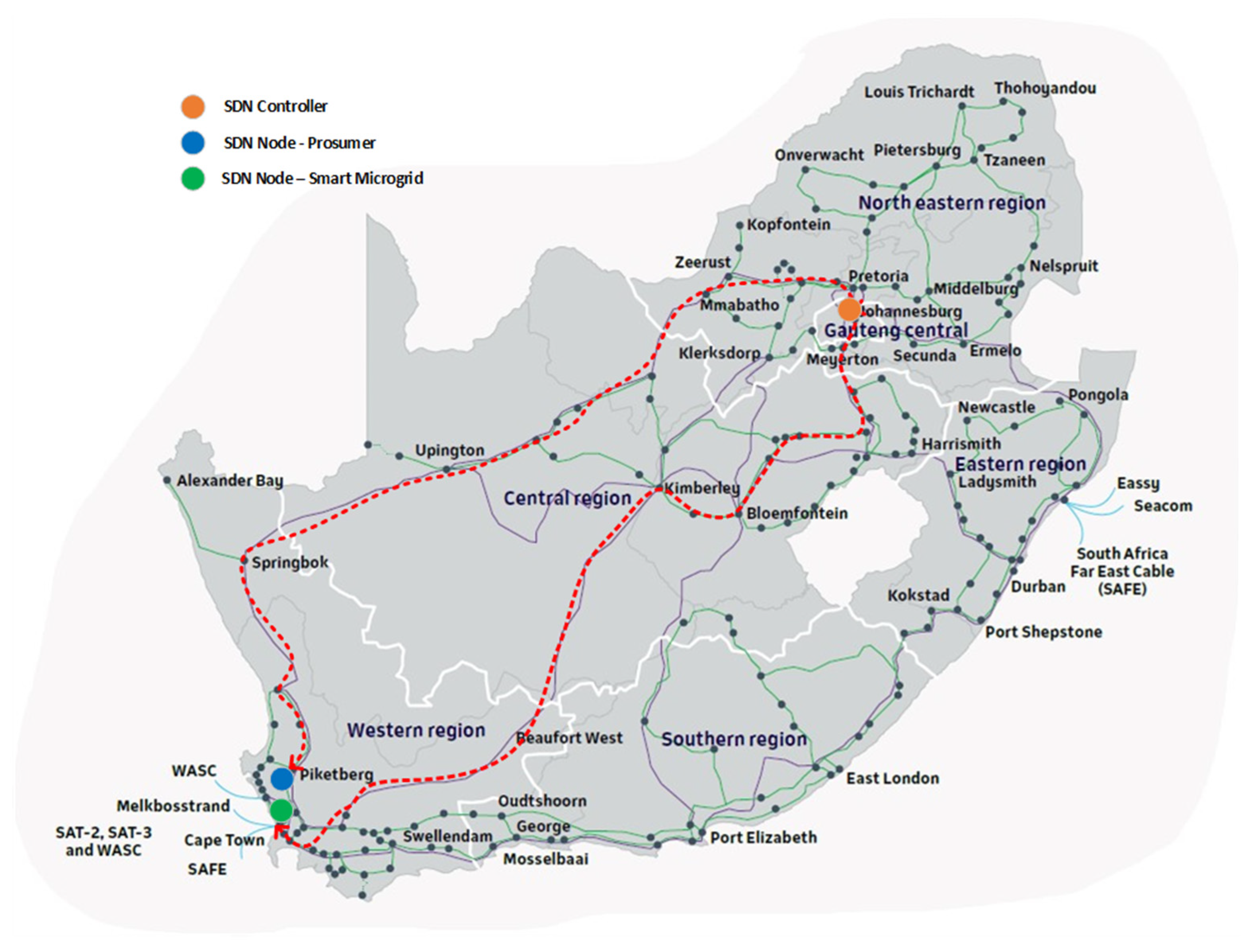
In a typical SDN architecture for this applied design scenario, the SDN controller will be hosted in Johannesburg with the Smart Microgrid SDN Node in Cape Town and Prosumer SDN Node in Piketberg.
Figure 18 shows the network coverage of Telkom with network exchange points which is represented by the dark points on the map. It also shows the geographical map of the node locations and the data path between the SDN controller and the SDN nodes. All the nodes are connected to the fixed line network of Telkom using a layer 2 connection on a dedicated virtual local access network (VLAN). The data paths between the SDN controller and the SDN nodes establish over multiple network nodes. The prosumer and smart microgrid are connected to the Eskom electrical grid, supplementing the energy supply to the national power grid. Both are participants in the transactive energy process. The unencrypted data path between the SDN controller and the SDN node at the smart microgrid establishes over 11 network nodes. The unencrypted data path between the SDN controller and the SDN node at the prosumer establishes over 16 network nodes. Traffic in a typical SDN architecture flow through the SDN controller, meaning the total number of network nodes between the prosumer SDN and the smart microgrid equates to 27.
The data path availability is calculated using Equation (5), and the availability of 99.99% is better than a physical network element in a traditional business network [
36],
The data path availability equates to 99.73%. Unfortunately, this also means the data path will experience outages of 120 min per month.
By implementing the optimized SDN architecture for TESMS, the following changes are performed to the architecture,
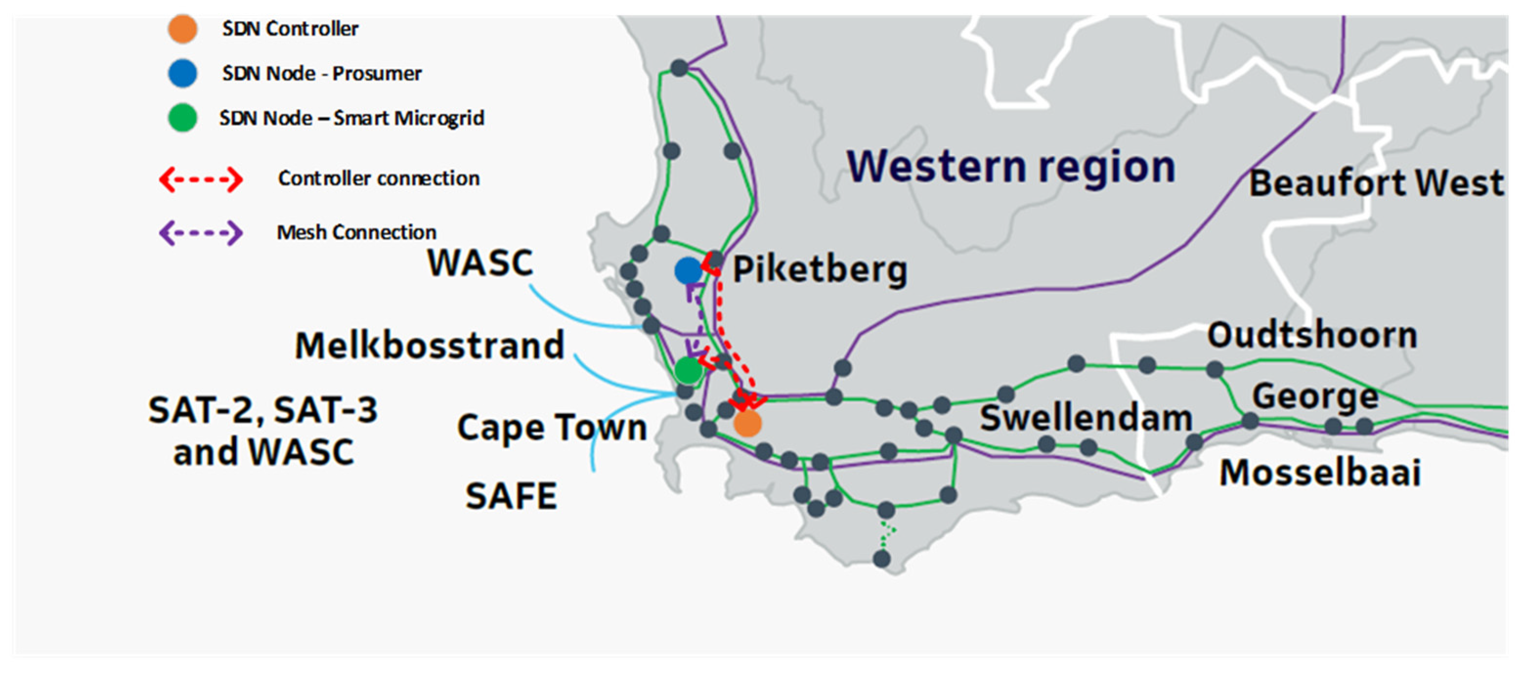
The SDN controller is decentralized, and the SDN controller for the region is placed at the hosting facility in Cape Town, Stellenbosch. As a result, the number of network nodes is reduced.
Mesh network topology is created by creating data paths between the prosumer SDN node and the smart microgrid SDN node. As a result, the number of network nodes on the data path is further reduced, and the number of data path route options increases.
The SDN nodes are configured to use dual internet connections for redundancy. Each node will connect to the Telkom fixed line network and an LTE ISP in the region.
Figure 19 shows the layout of the optimized SDN architecture with the decentralized controller located in a hosting facility in Cape Town, Stellenbosch, and the SDN nodes with a directly connected data path (without going through the controller).
The final data path availability equates to 99.99999%. The data path availability improves by 0.27%, reducing the data path downtime by 117 min per month. The controller algorithm improves flexibility by monitoring link stats and calculating new data paths in case of a link failure. However, the Floyd−Warshall algorithm takes longer than a second to switch the data path to the newly calculated route. This process indicates that the network element availability no longer determines data path availability but rather the SDN controller algorithm.
A VPN configuration on the data paths between the SDN nodes (controller, prosumer, and smart microgrid) is implemented to encrypt the data on the data path.
The decentralized controller placement and redundant link configuration improve the availability of the data path by reducing the number of network elements in the data path and providing alternative routes in the event of a failure. This design implementation improves the reliability of the SDN architecture. The mesh topology configuration with the controller algorithm improves the flexibility of the SDN architecture. The VNP configuration between all the SDN nodes improves the security of the SDN architecture. This applied design scenario proves that the optimized SDN architecture for TESMS improves reliability, flexibility, and security.
6. Discussion and Limitations
To improve the reliability of the SDN architecture, the design uses two methods, decentralized controller placement and redundant link configuration. The decentralized controller placement reduces the number of network elements in the SDN architecture. The redundant link configuration improves the availability of the SDN node, which improves the reliability of the SDN network. To improve the flexibility in the SDN architecture, a mesh topology with a Floyd−Warshall algorithm to calculate the shortest path between nodes is applied to the design. The shortest path algorithm is used if there is a change in the network condition, calculating the shortest path between nodes and improving the SDN architecture’s flexibility. Finally, to improve the security of the SDN architecture, data encryption using the IPsec protocol is applied to the design.
6.1. Reliability Improvements and Considerations in the SDN Architecture
Software-defined networking improves the reliability of a network by design. However, specific design parameters in the SDN architecture can be improved. The design considerations to improve the SDN architecture’s reliability are decentralized controller placement and redundant link configuration. These design considerations are not found in a typical SDN architecture design.
A decentralized controller placement reduces the number of network elements between the consumer and prosumer in the transactive energy process. The data path availability improves because of the reduction. The P2P trading strategy sequence experience an improved information flow, resulting in accurate and updated trade parameters.
A decentralized controller placement reduces the number of network elements in the data path and the resource requirement of the controller. Reducing the combined failure rate of the data path improves the reliability of the SDN architecture. A decentralized controller placement reduces the downtime of the data path and resource requirement of the controller by the factor of the reduction in the number of elements.
The negative impact of the decentralized controller placement is that another level of control is required to manage all the controllers through an east−west interface as per
Figure 3. Another impact to consider is the technology availability in certain areas that will not be able to provide a stable environment for the controller. Certain areas and environments still operate on legacy and outdated technologies. An unstable controller environment reduces the data path availability.
The redundant configuration improves the data path availability by providing an alternative communication link for the SDN node. A link failure during a transaction between the consumer and prosumer can continue if there is a redundant link configuration.
The negative impact of the redundant link configuration is the commercial aspect of the second link. A second agreement with a second ISP and vendor is required, which can complicate the management of the redundant link configuration. Another impact to consider is the technology availability for redundant link configuration. Certain remote areas only have one communication technology available, which makes a redundant link configuration not possible.
The improvement of the decentralized controller placement and redundant link configuration in the data path availability confirms the improvement in the reliability of the SDN architecture.
6.2. Flexibility Improvements and Considerations in the SDN Architecture
The design consideration to improve the flexibility of the SDN architecture is identified as a mesh topology configuration with a control algorithm that dynamically adapts to the changes in the link states between SDN nodes. Simulations are performed using a Mininet SDN network emulator to simulate a network of SDN nodes configured in a mesh topology. The controller code uses a Floyd−Warshall algorithm to determine the shortest path between SDN nodes continuously. This enables continuous information flow between the consumer and prosumer during the energy transaction in a dynamic network environment.
The negative impact of the mesh topology configuration is the requirement to enable the mesh configuration. All SDN nodes are required to be reachable on the same network level (data plane), which is difficult to achieve in a multi-tier public network such as the Internet. Another consideration is the technical capability to support the mesh topology configuration. Technologies such as geostationary VSAT communication links have certain limitations for site-to-site communication in a mesh topology.
The simulation proves that the mesh topology configuration with the control algorithm to determine the shortest data path dynamically improves the flexibility of the SDN architecture.
6.3. Security Improvement and Considerations in the SDN Architecture
The design consideration to improve the security of the SDN architecture is identified as implementing data encryption. Alternative security methods include designs to mitigate cyber-attacks and performance application-based routing. However, they do not protect the integrity of the data in the data packet. Simulation shows that encryption is required to hide the information from snooping software on the Internet effectively. IPsec is a secure method to encrypt the transactive energy information flow between SDN nodes in the transaction process.
The negative impact of the IPsec encryption between SDN nodes starts to become prominent when encryption between multiple nodes in a mesh topology is required. Complex solutions such as a mesh VPN configuration are required to achieve the security and flexibility requirement.
Data encryption, however, improves the security of the SDN architecture.
The proposed design and simulation of a suitable SDN architecture for TESMS provides a significant improvement in reliability and flexibility and should be used as guidelines for the practical deployment of SDN TESMS networks.
7. Conclusions
Transactive energy (TE) consists of economic and control mechanisms to balance the supply and demand of energy on an electrical network. The link between economics and energy is transactive, with various participants in the transactive energy process. These participants include consumers, prosumers, utility networks, and distributed energy sources such as SMGs. The participants of transactive energy use different types of markets, including the forward market for future delivery of energy in a pre-paid energy market concept and the spot market for real-time energy delivery in a pay-per-use commercial model. Literature also confirms that the primary communication is between local participants of the TE process. Therefore, there is a requirement for a reliable, flexible, and secure network for transactive energy.
There is also a research gap in the literature on transactive energy for reliability, flexibility, and security in traditional IP network infrastructure. Software-defined networking (SDN) emerged to meet the requirements of complex networks. However, the research found that application-aware SDN architectures are designed to meet the specific application’s requirements. This revelation confirms the need to develop an SDN network that meets the requirements for transactive energy in smart microgrids. In addition, the optimized SDN architecture is required to improve the network’s reliability, flexibility, and security.
7.1. Application of Developed SDN Architecture as a Case Study
An application of the optimized design is investigated in a hypothesized scenario whereby a prosumer and smart microgrid are in Cape Town. The typical SDN architecture evaluated the data path availability with the controller located in Johannesburg. The optimized SDN architecture design was applied by decentralizing the SDN controller, adding a redundant network connection to each SDN node and changing the network layout to a mesh topology configuration with automated failover. As a result, the data path availability improved by 0.27%, which resulted in a data path downtime reduction of 117 min per month.
7.2. Recommendations and Planned Research
Reliability and flexibility design considerations are not limited to the network node availability and automated failover. SDN architecture reliability also relies on the SDN controller availability. The data paths can be established and available. However, the entire SDN network goes down if the controller goes down. Therefore, design considerations to mitigate controller failure can be investigated. Design considerations such as controller redundancy and automated failover should be investigated.
The number of network nodes between SDN nodes is not the only performance indicator to determine the shortest path between SDN nodes. Link quality is another performance indicator that includes parameters such as latency, jitter, packet loss and metered connections. Flexibility design consideration could include a link quality indicator to determine the best shortest path between SDN nodes. Other design considerations should include link cost factors to determine the shortest path.
Although a mesh topology improves the flexibility of the SDN architecture, further studies on the practical implications could be researched, that includes technology limitations and security considerations in a mesh topology.
