Abstract
The thrust from corona discharge might be a promising propulsion technology in future aviation due to its advantage of not requiring mechanical moving parts. Although the thrust from corona discharge has been researched by many scholars, the effect of the applied voltage’s polarity on the thrust has received little attention. This polarity effect might be very important for some special electrohydrodynamic thrusters. This paper firstly built a test platform to reveal the effect of the applied voltage’s polarity on both the thrust and the corona current from a pair of symmetrically distributed needle electrodes. Then the applied voltage’s polarity on the electrical field distribution between a pair of needle-plate electrodes was simulated. Finally, the relationship between the space ions at the tip of the needle electrode and the thrust are discussed. The results show that a negative needle electrode with a smaller curvature radius has a stronger thrust than a positive one with a larger curvature radius, and a stronger thrust corresponds to a higher corona current. The local electric field is enhanced by the space ions at the tip of a negative needle electrode, while it is weakened by a positive needle electrode. This results in the polarity of thrust.
1. Introduction
When high voltage is applied to a pair of asymmetric electrodes, thrust will generate between the electrodes. This thrust was first discovered by Biefeld and Brown [1]. However, there is still no definite theoretical explanation of this phenomenon, even as many studies have adopted the reaction force of ionic wind to explain it [2,3,4,5]. Subsequently, it has received extensive attention due to the potential of its widespread application in future aviation on account of its advantage of requiring no mechanical moving parts.
Although the theory of the Biefeld-Brown effect has been thoroughly developed, the mechanism responsible for the reactive force acting on the electrode surface is still a current research hotspot. Kim Chul et al. [6] investigated electrode charges and their resultant Coulomb forces for a wire-to-cylinder EHD thruster that produces positive corona discharge. Additionally, the authors think that the inequality of charges and forces on the electrodes is caused by the volume charge that appears in the applied voltage when it is higher than the corona onset voltage.
In recent years, theoretical and practical studies on the corona discharge thrust have been conducted one after another. For instance, studies have examined the characteristics of corona discharge thrust with various shapes of electrodes and different electrode parameters. Wang Wei et al. [7] studied the thrust characteristics of the multi-points/grid electrode, and obtained the voltage control function of the thrust generated by the structure. At the same time, the experiment results show that the increase in the number of point electrodes and their spacing improves the electrode structure thrust under the same voltage. Kiousis K.N et al. [8] studied the thrust generated by the electro-hydrodynamic (EHD) effect of a wire-cylinder arrangement under high DC voltage, and they concluded that a larger gap and collector radii favor the thrust per unit power ration. Huang Ping et al. [9] simulated and analyzed the physical process of corona discharge between two electrodes with a classic line-aluminum foil structure, and concluded that the ionic wind’s numerical value can be affected by some structural parameters of the electrode system.
Since the direction of thrust generated by the corona discharge is directed to the discharge electrode without consideration for the applied voltage polarity, most researchers have only studied a single polarity electrode rather than different polarities. Studying the latter might lead to different results, which could make the thruster more efficient, or have less dielectric cost. Although Sohbatzadeh F et al. [10] utilized a DC superimposed AC (AC-DC) voltage source to achieve a higher thrust efficiency, they did not compare and select the polarity of the DC voltage. In addition, Yuan Junxiang [11] and Miu Jinsong [12] measured the ion wind velocity between a pair of needle-plate electrodes using different methods, thereby reaching conflicting conclusions on the relationship between the polarity and the ion wind velocity. Furthermore, they did not measure and analyze the corona discharge thrust at different polarity voltages. The development process and the state of corona discharge are very different under different polarity voltages; therefore, it is very important to inspect the effect of polarity on the thrust.
In this paper, an experimental platform is designed firstly to test the thrust from a pair of symmetrically distributed needle electrodes with different polarities and curvatures. Then, the applied voltage’s polarity on the electrical field distribution between a pair of needle-plate electrodes was simulated. Finally, the relationship between the space ion in front of the needle electrode and the thrust are discussed.
2. Experimental Setup
Figure 1 shows the experimental setup. A piece of non-corona copper rod (the edges of the non-corona copper rods used in the experiment are smooth and round, and corona discharge is unlikely to occur) of 10 mm in diameter and 1 m in length was connected horizontally to the high voltage power supply (HVDC) U0. At the midpoint of the copper rod, a piece of stainless-steel wire, W1, with a length of 1 m and diameter of 0.1 mm was vertically fixed. Another piece of “Z”-shaped stainless-steel wire, named electrode W2, was placed 0.2 m above ground, and was connected horizontally and symmetrically to the tail of W1. W2’s arm length L1, its needle length L2, and chamfer diameter r2, were 95 mm, 20 mm and 2 mm, respectively. Two different diameters of W2, 130 μm and 80 μm, were used to test the effect of the electrode curvature on the thrust.
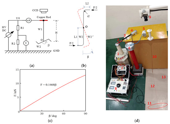
Figure 1.
Experimental setup for testing corona thrust from a pair of needle electrodes: (a) Schematic diagram of the total experimental setup; (b) Schematic definition of the deflection angle β of the “Z” shaped needle electrode W2; (c) Relationship between thrust F from the tips’ corona discharge of electrode W2 and deflection angle β of electrode W1; (d) Photos of the test site, 1—high voltage transformer, 2—current resister, 3—rectifier diode, 4—filtering capacitor, 5—micro-ampere meter, 6—voltage divider, 7—voltage digital displayer, 8—autotransformer, 9—digital camera, 10—corona-free copper rod, 11—electrode W2 (marked with a red circle), 12—stainless steel wire W1, 13—ground.
A voltmeter was used to measure the supply voltage by a resistive divider R1-R2, and a micro-ammeter measured the corona current. There was also a digital camera CCD mounted 0.5 m above the corona-free copper rod to simultaneously record the values of the supply voltage, corona current, and rotation the of angle β of electrode W2. The recorded images were transmitted to a computer for further analysis.
Figure 1c shows the photos of the test site. Among them, the high-voltage DC power supply U0 is obtained by the AC 220 V power, which in turn is obtained through the power frequency AC step-up transformer, “1” (50 kV, 5 kW) step up, the resistance “2” (37 kΩ) current limiting, the silicon stack “3” (2CL 300kV / 2.0 A) rectification, and the capacitance “4” (10 nF) filtering. The voltage value can be controlled by the voltage regulator “8”, and read out on the display screen “7” after passing through the voltage divider “6”. In addition, “5” is a microampere ammeter, “10” is a corona-free copper rod, “12” is a stainless-steel wire W1, “11” is an electrode W2, “9” is a digital camera, and “13” is a grounded floor.
In Figure 1, the rotation angle β will increase with the increase of the power supply. During the experiment, no obvious deformation of W2 was observed.
As shown in Figure 1d, a simulation model was established in this research to reveal the relationship between the torque generated by electrode W2’s corona thrust and the torsion angle β of W1. In this model, the upper end of W1 is fixed, and the rotation angle β is set to the lower end. The simulation indicates that the thrust F is approximately proportional to the rotation angle β. Therefore, the thrust F is:
where the unit of thrust F is mN, and the unit of rotation angle β is deg.
3. Experimental Results
3.1. Effect of Electrode Curvature and Polarity on Thrust
The relationship between the thrust and the applied voltage with different polarities was obtained, as shown in Figure 2.
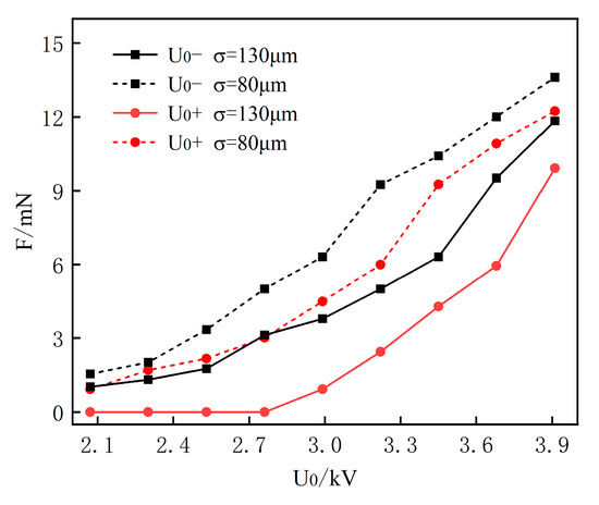
Figure 2.
Corona thrust F at different voltage U0 and voltage polarity.
It can be seen from Figure 2 that the reverse thrust of the needle electrode W2 with negative voltage is greater than that of the needle electrode with positive voltage, if the voltage value is the same. In addition, the thrust almost remains at 0 until the positive voltage U0 is increased to a threshold value (approximately 2.02 kV). Thereafter, the thrust increases gradually with the increase of voltage U0. This indicates that a positive electrode has a higher rotation starting voltage than a negative one.
The curvature of the needle electrode has a certain influence on the spatial electric field distribution at the front end of the electrode during corona discharge [13]. Two types of electrodes W2, with wire diameters of 130 μm and 80 μm, were used to represent the tip curvature of the electrodes. The force arm L1 and the tip length L2 of electrode W2 were kept constant in the experiment. The relationship between the magnitude of the two different diameters of the curvature on the rotation angle of electrode W2 was compared for voltage U0 in positive and negative polarities, as shown in Figure 2. A smaller electrode curvature or diameter of W2 (80 μm) has stronger thrust, while a bigger one (130 μm) has weaker thrust. Moreover, the thrust from a negative electrode W2 is greater than that from a positive one under the same voltage values.
3.2. Effect of Polarity on Corona Current
The corona currents for both positive and negative electrodes at different voltages were measured with an ampere (μA) when the curvature diameter of W2 was 130 μm, as shown in Figure 3. It can be seen that the corona current increases with the increase of applied voltage U0, regardless of the voltage’s polarity. Another obvious trend can be found, which is that a negative needle electrode has a stronger corona current than a positive one at the same voltage.
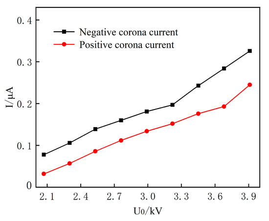
Figure 3.
Applied voltage (U0) and corona current (I) with W2’s diameter of 130 μm.
The experimental results of the thrust from the corona discharge of the needle electrodes W2 show that: (1) The thrust generates only when the voltage of the needle electrode reaches a threshold value; (2) The smaller the curvature diameter of the corona electrode is, the stronger the thrust is; (3) The corona current and thrust will be greater when the needle electrode is charged with negative voltage than with positive voltage.
4. Electric Field Numerical Simulation
4.1. Simulation Model
Based on fluid dynamics theory, a mathematical model of particle diffusion reflecting the generation and disappearance of space ions formed by corona discharge was established. Then, the problem was solved using the Poisson equation to simulate the corona process dis-charge [14]. The following continuity equations for electrons, positive ions and negative ions, as well as Poisson’s equation are given below:
Equations (2)–(4) are the continuity equations for electrons, positive and negative ions, in that order, and Equation (5) is the Poisson equation for the electric field. Where Ne, Np, Nn, μe, μp, μn, De, Dp, Dn are the number density (1/m3), mobility (m2/(V·s)), the diffusion coefficient of electrons (m2/s), and positive and negative ions, respectively; α is the collision ionization coefficient (1/m); η is the electron attachment coefficient (1/m); kpe is the positive ion-electron complex coefficient (m3/s); kpn is the positive-negative ion complex coefficient (m3/s); E is the electric field strength vector (V/m); U is the applied voltage (V); ε0 is the vacuum dielectric constant (F/m); Sph is photo ionization source term (1/m3·s), e is the unit of element charge (e = 1.69 × 10⁻¹⁹ C), and the Helmholtz photo ionization calculation model was used in the article [15].
For the setting of the parameters in the control equations, the air discharge parameters proposed by Nikonov et al. [16] are used in this paper. The specific expressions of each parameter are shown in Table 1 (p is the gas pressure, Pa; E is the electric field intensity, V/cm).

Table 1.
Air discharge parameters proposed by Nikonov et al.
The corona current formed by the directional movement of charge in the needle-plate gap can be expressed by the research results of Sato et al. [17]:
where V is the applied voltage; s is the cross section of the discharge channel; e is the electric field intensity vector; EL is the Laplace electric field intensity of the discharge channel.
In order to analyze the distribution of the ion distribution in the corona discharge, a two-dimensional axisymmetric needle-plate discharge model (where r = 0 denotes the axis of symmetry) which is easier to solve was adopted in this paper, as shown in Figure 4. Although the ions’ distribution for a single electrode is different from a pair of two-dimensional axisymmetric needle-plate electrodes, the chemical reactions are the same, and both share a similar electric field structure.
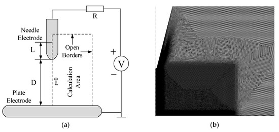
Figure 4.
(a) Needle-plate corona discharge simulation model; (b) Mesh grids dissection in the calculational area.
In the needle-plate geometric model, the needle-plate gap (D), the tip length (L), and the diameter of curvature (σ), were set to be 3 mm, 4 mm, and 130 μm or 80 μm, respectively. The ambient temperature during the gas discharge and the background pressure were set to be 300 K and 1atm, respectively. The external DC voltage V0 at the tip of the needle can be changed according to different demands.
In order to accelerate the convergence speed of the simulation and the formation of the corona current pulse, the initial particle concentration in the discharge space needs to obey the Gaussian distribution. In this paper, the peak value of the distribution is set to 1 × 10¹³ m−3, which is the maximum particle density at the tip of the needle. It then decreases according to the Gaussian distribution after being far away from the tip of the needle:
here, Nmax = 1 × 10¹³ m−3; s0 is a Gaussian distribution domain, s0 = 25 μm; r0 and z0 are the horizontal and vertical coordinates of the tip, respectively.
In addition, the setting of boundary conditions is a crucial aspect of the numerical simulation model of fluids. The boundary conditions in the simulation were described as follows [18].
The boundary conditions for electron, ion and neutral particle fluxes at the needle-plate electrodes are as follows:
where Γe, Γi and Γs denotes the electron, ion and neutral particle density fluxes, respectively, 1/(m2·s); vth.s, vth.i and vth.s denote the electron, ion and neutral particle thermal rates, m/s; γi denotes the secondary electron emission coefficient, which here takes the value of 0.05.
For the open boundary, all particles need to satisfy and the potential needs to satisfy .
4.2. Simulation Results
Figure 5 shows the corona current waveform for both negative and positive needle-plate electrodes. The diameter of curvature of the needle electrode and the applied voltage U0 were set to 130 μm and ±4 kV, respectively. Pulse shaped current waveform is observed after the simulation voltages were applied. The amplitude, frequency and duration of a single pulse are 7.2 μA, 50 kHz and 20 μs for positive corona discharge, and 431 μA, 570 kHz and 1.76 μs for negative corona discharge, respectively.
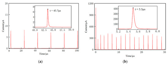
Figure 5.
Corona current obtained by simulation. (a) Positive polarity; (b) Negative polarity.
Although the negative corona current pulse lasts for a shorter interval of time, the pulse frequency and the amplitude are both much higher than the positive discharge. It can be derived from this that the ionic wind produced by the corona discharge of the negative polarity is much stronger than that produced by the positive one, and the negative corona discharge occurs more easily, resulting in greater thrust.
The simulation result shows that the ion density at the tip of needle electrode reaches the maximum value at the pulse peak time [19]. Figure 6 shows the ion distributions at a certain pulse peak time for both positive and negative polarity. It can be clearly seen that the density of each ion in the gap is larger during negative corona discharge. In addition, the density of positive ions is higher than that of the negative by one to two orders of magnitude, which indicates that there are more net positive ions for both positive and negative polarities. From the space charge density distribution map, it can be known that the negative electrode tip has more net positive ions than the positive electrode tip.
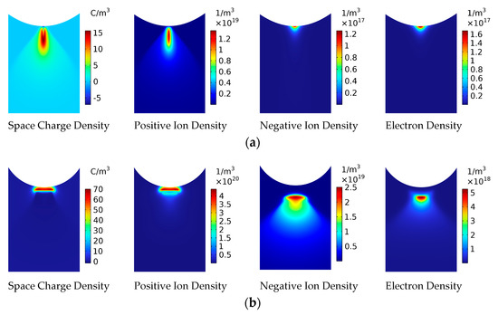
Figure 6.
Ion distribution diagram at peak time of current pulse. (a) Positive polarity (t = 43.7 μs); (b) Negative polarity (t = 5.5 μs). Total ion distribution.
Figure 7 shows the partial electric field along the axis of the needle electrode. It can be seen from this figure that the extra electric field formed by the positive ions in front of the needle electrode strongly distorted the original electric field. Two obvious trends are: (1) A smaller diameter of curvature leads to a stronger electric field at the tip of the needle and then produces an intense corona discharge if the applied voltage is the same. (2) The local electric field strength in front of the negative needle electrode is higher than that of the positive if the diameter of needle electrodes is the same, which generates stronger corona and thrust.
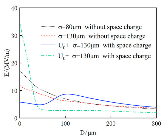
Figure 7.
Electric field intensity (E) along needle electrode axis (D) at peak time of current pulse.
5. Discussion
5.1. Analysis of Relationship between Voltage and Thrust
Based on Peek’s formula, the formula for the corona onset voltage of the needle electrode can be derived [20] as follows:
where R is the radius of curvature of the needle electrode (unit: cm); d is the gap distance (unit: cm); E0 is the critical field where ionization is significant, E0 = 31δ (unit: kV/cm); δ is the relative air density factor, δ = 0.392P/T (P is the unit of air pressure mmHg, T is the unit of temperature K).
In order to estimate the starting corona voltage of electrode W2 in this experiment, the atmospheric condition is considered to be essentially constant with δ = 1. Since the electrode tested in this experiment is a single electrode, d is taken as the distance between the tip of W2 and the earth for calculation (about 20 cm in the experiment).
The calculation shows that the corona starting voltage is 2.0 kV when the diameter of the needle electrode is 130 μm. This value is very close to 2.08 kV, namely the rotation starting voltage of electrode W2 in negative polarity. This indicates that corona discharge is the precondition for the generation of thrust.
5.2. Relationship between Curvature and Thrust
Although the linear relationship between the radius of curvature of the electrode and the intensity of corona discharge is well known, it is necessary to analyze it to ensure the accuracy of the experiment in this paper.
The experimental results in Figure 2 show that the smaller the diameter of curvature σ of electrode W2, the larger the rotation angle β, and the stronger the thrust F. This is mainly due to the fact that the needle electrode with the smaller radii (or diameter) of curvature produces a stronger partial electric field at the same voltage.
The simulation results in Figure 7 also show that the smaller the diameter of curvature σ, the higher the local electric field intensity in front of the electrode. At the same applied voltage, the higher the local electric field is, the stronger the corona discharge is that occurs, and the greater the thrust that is generated, if the applied test voltage is the same.
5.3. Relationship between Polarity and Thrust
The experimental results above show that at the same applied voltage, the thrust at the tip of the negative needle electrode is greater than that of the positive one. This is due to the distortion of the electric field near and in front of the tip of the needle electrode by the space ion from the corona discharge. Additionally, for different voltage polarities, the space ions generated by the discharge have different distortion effects on the local electric field near the tip of the needle electrode.
In Figure 7, when the needle electrode is charged by positive voltage, electrons in the vicinity of the needle electrode immediately enter the needle electrode, leaving behind positive ions due to its heavy weight and slow-moving speed. Therefore, the local electric field between the positive electrode and the positive ions is weakened (the blue solid line in Figure 7). The corona initiation voltage is high. When the needle electrode is charged by negative voltage, electrons in the vicinity of the needle electrode enter the plate electrode, leaving behind positive ions, too. Then, a large number of positive ions accumulate in front of the negative needle electrode. After the accumulation of positive ions, a strengthened local electric field appears between the negative needle electrode and the accumulated positive ions (the green dotted line in Figure 7). Electrons are easy to eject from the needle electrode into the air with the aid of a strengthened local electric field. Furthermore, the negative needle electrode ejects electrons more easily than air due to the fact that the energy required to remove an electron from metal is lower than the ionization energy for air molecules. Consequently, the corona discharge starting voltage is low. If the applied voltage is the same, the corona current of the negative needle electrode is greater than that of the positive one, and thus the ion wind velocity.
6. Conclusions
This paper has designed an experimental platform for a corona discharge thrust test on a centrosymmetric electrode. The relations between the corona discharge thrust and the applied voltage’s polarity were studied and discussed.
The experimental results verified the general conclusion that the electrode curvature is positively correlated with the corona discharge intensity, or the corona discharge thrust. Furthermore, the difference in corona discharge thrust effect is very obvious when different polarity voltages are used. The experimental results show that a needle electrode with negative voltage leads to easier corona discharge, and a linear relationship between the generated thrust and the discharge current if other conditions are the same. Then, the experimental result is further analyzed and explained by the numerical simulation results of corona discharge at different polarity voltages. Therefore, it might be because of the space ion in front of the negative electrode enhances the local electric field and surface ionization at the tip of needle electrode, which generates stronger thrust. In other words, if the positive and negative corona discharges produce the same thrust, a needle electrode with a positive voltage is required to apply a higher voltage. Moreover, this will lead to the serious consequence that the needle-plate gap becomes more easily broken down. In summary, the research results of this paper show that it is more efficient and safer to choose negative voltage in a corona discharge thrust device.
This study might be used in the future in the fields of aviation or electric propulsion. While achieving the same energy efficiency, the voltage level required for negative corona discharge is lower, so the performance requirements of the insulating medium in the propulsion device are not high, which can decrease the use cost of dielectric.
Author Contributions
Conceptualization, L.G. and W.T.; methodology, L.G.; software, W.T.; validation, W.R.; formal analysis, L.G.; investigation, W.R.; resources, Z.J. (Zheng Jiang); data curation, Z.J. (Zhuangzhuang Jin); writing—original draft preparation, W.T.; writing—review and editing, J.H.; visualization, J.H.; supervision, X.C.; project administration, L.G.; funding acquisition, Z.J. (Zheng Jiang). All authors have read and agreed to the published version of the manuscript.
Funding
This research was funded partly by the National Power Grid Science and Technology project (SGCQBS00YJJS2250077), partly by Chongqing University of Technology’s National Nature Fund training program (2021PY211) and partly by the Project of innovative talents training of Chongqing Municipal Education Commission (CY230901).
Data Availability Statement
Not applicable.
Conflicts of Interest
The authors declare no conflict of interest.
References
- Brown, T.T. A Method of and an Apparatus or Machine for Producing Force or Motion. GB300311A, 15 November 1928. [Google Scholar]
- Makrinich, G.; Fruchtman, A. Enhancement of electric force by ion-neutral collisions. Appl. Phys. Lett. 2009, 95, 181504. [Google Scholar] [CrossRef]
- Colas, D.F.; Ferret, A.; Pai, D.Z.; Lacoste, D.A.; Laux, C.O. Ionic wind generation by a wire-cylinder-plate corona discharge in air at atmospheric pressure. J. Appl. Phys. 2010, 108, 103306. [Google Scholar] [CrossRef]
- Monrolin, N.; Praud, O.; Plouraboué, F. Electrohydrodynamic ionic wind, force field, and ionic mobility in a positive dc wire-to-cylinders corona discharge in air. Phys. Rev. Fluids 2018, 3, 063701. [Google Scholar] [CrossRef]
- Vaddi, R.S.; Yifei, G.; Mamishev, A. Analytical model for electrohydrodynamic thrust. Proc. R. Soc. A Math. Phys. Eng. Sci. 2020, 476, 2020220. [Google Scholar] [CrossRef] [PubMed]
- Kim, C.; Lee, S.; Lee, H.G. Characterization of electrode charges and forces in an electrohydrodynamic thruster. AIP Adv. 2022, 12, 115318. [Google Scholar] [CrossRef]
- Wang, W.; Yang, L.; Huo, P.; Wu, K. Thrust characteristic of a multipoint-grid type EHD gas pump under negative corona operation in air. IEEE Trans. Dielectr. Electr. Insul. 2015, 22, 2136–3141. [Google Scholar] [CrossRef]
- Kiousis, K.N.; Moronis, A.X.; Fruh, W.G. Electro-hydrodynamic (EHD) thrust analysis in wire-cylinder electrode arrangement. Plasma Sci. Technol. 2014, 16, 363–369. [Google Scholar] [CrossRef]
- Huang, P.; Xie, Z.-Y.; Liu, P.; Leng, D.-P.; Zheng, J.-P.; Wang, S. Ionic Wind Simulation of Wire-Aluminum Foil Electrode Structure Lifter in 2-D Space. IEEE Trans. Plasma Sci. 2022, 50, 566–573. [Google Scholar] [CrossRef]
- Sohbatzadeh, F.; Soltani Ahmadi, H.; Mirzanejhad, H. Enhancement of thrust force of an atmospheric pressure positive corona discharge by DC superimposed AC high voltage. J. Phys. D Appl. Phys. 2022, 55, 445201. [Google Scholar] [CrossRef]
- Yuan, J.; Qiu, W.; Zheng, C. Study on Characteristics of Ionic Wind from Atmosphere Discharge. Proc. CSEE 2009, 29, 110–116. [Google Scholar]
- Miao, J.; Chen, Y.; Zhang, Y.; Jin, Z. Comparison of Positive and Negative Ionic Wind in Needle-to-Plate Corona Discharge. Trans. Beijing Inst. Technol. 2017, 37, 61–66. [Google Scholar]
- Zhang, L.; Sheng, G.; Hou, H.; Song, H.; Jiang, X. Influence of Protrusion Tip Size on Current Pulse Characteristics of Negative Corona Discharge Based on Numerical Simulation. IEEE Trans. Power Deliv. 2022, 37, 3792–3802. [Google Scholar] [CrossRef]
- Georghiou, G.E.; Papadakis, A.P.; Morrow, R.; Metaxas, A.C. Numerical modelling of atmospheric pressure gas discharges leading to plasma production. J. Phys. D Appl. Phys. 2005, 38, R303. [Google Scholar] [CrossRef]
- Liu, N.; Pasko, V.P. Effects of photoionization on propagation and branching of positive and negative streamers in sprites. J. Geophys. Res. 2004, 109, A04301. [Google Scholar]
- Nikonov, V.; Bartnikas, R.; Wertheimer, M.R. Surface charge and photoionization effects in short air gaps undergoing discharges at atmospheric pressure. J. Phys. D Appl. Phys. 2001, 34, 2979–2986. [Google Scholar] [CrossRef]
- Morrow, R.; Sato, N. Discharge current induced by the motion of charged particles in time-dependent electric fields; Sato’s equation extended. J. Phys. D Appl. Phys. 1999, 32, L20. [Google Scholar] [CrossRef]
- Hagelaar, G.J.M.; De Hoog, F.J.; Kroesen, G.M.W. Boundary condition in fluid models of gas discharges. Phys. Rev. E 2006, 62, 1452–1454. [Google Scholar] [CrossRef] [PubMed]
- Napartovich, A.P.; Akishev, Y.S.; A Deryugin, A.; Kochetov, I.V.; Pan’Kin, M.V.; Trushkin, N.I. A numerical simulation of Trichel-pulse formation in a negative corona. J. Phys. D Appl. Phys. 1997, 30, 2726. [Google Scholar] [CrossRef]
- Forana, I.; Broual, A. A predictive model of the positive discharge in long air gaps under pure and oscillating impulse shapes. J. Phys. D Appl. Phys. 1997, 30, 1653. [Google Scholar]
Disclaimer/Publisher’s Note: The statements, opinions and data contained in all publications are solely those of the individual author(s) and contributor(s) and not of MDPI and/or the editor(s). MDPI and/or the editor(s) disclaim responsibility for any injury to people or property resulting from any ideas, methods, instructions or products referred to in the content. |
© 2023 by the authors. Licensee MDPI, Basel, Switzerland. This article is an open access article distributed under the terms and conditions of the Creative Commons Attribution (CC BY) license (https://creativecommons.org/licenses/by/4.0/).