Abstract
The paper presents modern technologies of electrochemical energy storage. The classification of these technologies and detailed solutions for batteries, fuel cells, and supercapacitors are presented. For each of the considered electrochemical energy storage technologies, the structure and principle of operation are described, and the basic constructions are characterized. Values of the parameters characterizing individual technologies are compared and typical applications of each of them are indicated. Selected characteristics illustrating properties of the presented electrochemical energy storage devices are also shown. The advantages and disadvantages of the considered electrochemical energy storage devices and typical areas of their application are indicated. In addition, new, constantly developing technologies, not yet commercially available, are mentioned. Examples of existing energy storage solutions using the discussed technologies on the example of electric cars or storage systems in the world are given.
1. Introduction
In accordance with the energy policy in the field of decarbonization implemented in the European Union, it is assumed that by 2030 the emission of harmful substances into the environment will be reduced by 40% in relation to the aforementioned substances emitted in 1990 [1,2]. In response to the mentioned policy, searches for new zero-emission energy sources and solutions aiming at reducing harmful substances in the environment began.
Recently, a lot of attention has been devoted to obtaining energy from renewable energy sources (RES). The growing interest in the aforementioned methods of electricity generation is accompanied by the problem of its storage [3,4,5]. In the case of energy systems based on RES, in which energy sources are characterized by high instability depending on weather conditions, the use of the appropriate energy storage solutions is of the utmost importance. This makes it possible to increase the stability of the energy system and maintain the adequate energy security [6,7].
However, energy storage is used not only in extensive energy systems, but also in the automotive industry (electric vehicles), military industry (radio communication, drones), emergency systems (lighting) and in consumer devices (power tools, laptops, smartwatches, smart-phones, etc.) [8,9,10].
The problem of energy storage is not a new issue. The first energy storage system was invented in 1859 by the French physicist Gaston Planté [11]. He invented the lead-acid battery, based on galvanic cells made of a lead electrode, an electrode made of lead dioxide (PbO2) and an approx. 37% aqueous solution of sulfuric acid acting as an electrolyte. This type of battery is still widely used today [11].
Besides the mentioned method of energy storage, there are also well known other energy storage methods, which include pumped-storage power plants, fuel cells, compression energy storage, supercapacitors, kinetic energy storage, electrochemical energy storage and superconducting magnetic energy storage [12,13]. Each of these technologies is constantly being developed, depending on the application. It is worth noting that many papers are also devoted to the search for new ecological materials or the recovery of substances, e.g., aluminum from Coca Cola cans for the construction of, e.g., supercapacitors [14,15].
The aim of this paper is to review the currently available electrochemical technologies of energy storage, their parameters, properties and applicability. Section 2 describes the classification of battery energy storage, Section 3 presents and discusses properties of the currently used batteries, Section 4 describes properties of supercapacitors. Section 5 is devoted to fuel cells, and the comparison of the considered battery is included in Section 6.
2. Classification of Energy Storage Technologies
In the literature, there are many criteria for dividing energy storage technologies. The classification of energy storage technologies most often described in the literature is the classification that distinguishes the type of the used technology.
Taking into account the aforementioned criterion, in practice there are eight solutions, which include:
- The hydrogen energy storage system is basically related to the production and storage of hydrogen. It operates on the principle of water electrolysis. When the electrolyzer is supplied, water is split into hydrogen as the electrical energy carrier and oxygen, which are separated and stored in suitable tanks. It is worth noticing that hydrogen is characterized by the highest specific energy of 33 Wh/kg and a calorific value of 120 MJ/kg.
- SMES—Superconducting Magnetic Energy Storage. These systems are characterized by a short response time (i.e., the time in which the device can react and supply or take energy from the storage) and relatively high power. The basis of this group of energy storage systems’ functioning is accumulation of energy in the magnetic field of induction coils made of superconductors. Due to the fact that these systems operate at very low temperatures (below the temperature of liquid nitrogen), they can be successfully used in the range of very high currents (of the order of kA). Magnetic energy storage tanks are characterized by very high efficiencies of up to 95%, long expected service life (up to 30 years) and are capable of transferring high power (in the order of MW). They are also environmentally friendly due to the lack of toxic consumables and are reliable because there are no moving parts. On the other hand, their disadvantage is low energy density.
- Pumped-storage waterpower plants. These are one of the most popular and the oldest solutions. The main task of a pumped storage power plant is to balance the power in the energy system. Due to the losses in the turbo-set and the loss of evaporated water in the considered power plants, only 70–75% of the energy used to pump water to the upper reservoir is recovered [15]. Taking into account the size of the considered solutions, which depend on topographic and geological factors, these systems require a thorough technical and economic analysis, because the construction of a pumped-storage power plant is a very expensive investment.
- Liquefied Air Energy Storage (LAES) and Compressed Air Energy Storage (CAES). The Liquefied Air Energy Storage (LAES) method consists in using excess energy to compress air, which is then cooled to a very low temperature and liquefied as liquid air. When there is a demand for energy, the liquid air is heated, which causes it to expand and drive a turbine, which in turn generates energy. The efficiency of the energy storage process in liquefied air depends on the possibility of using the waste heat in the process of expanding the working medium and the heat generated in the process of charging the tank with liquefied air. According to paper [16], it is estimated that the real efficiency of the considered solution should reach about 60%. In the second case, CAES, the energy storage process using the mentioned method consists in compressing the air using an engine or turbine, and then storing the compressed air in underground tanks or cisterns. The air is compressed to a pressure of 70 atmospheres. When electricity is required, the compressed air is released to spin a turbine, which in turn powers an electric generator to produce the desired electricity [17]. One of the biggest advantages of CAES is that much larger amounts of energy can be stored with this method of energy storage than in batteries or other forms of energy storage. In addition, CAES has relatively low investment costs and is quite easy to use, which means that it can be used in both large and smaller power systems. However, this technology has some disadvantages. The process of compressing air requires significant amounts of energy, which means that the process can lead to a significant loss of energy in the conversion and storage process. Moreover, this process is usually used to store energy for a short period of time (e.g., hours) [18].
- Flywheel. Electric energy in such a solution can be stored in the form of flywheel kinetic energy. The capacity of such a storage solution depends on the rotating mass, its shape and the speed of rotation. The rotating mass is connected to the motor-generator, which accelerates the wheel during loading and slows down during unloading of the warehouse [19]. Flywheel units can achieve efficiency of over 80%, and their self-discharge rate is less than 3%/h. The use of a superconducting magnetic bearing allows the reduction of the self-discharge rate to less than 0.5%/h [20].
- Thermal method of energy storage. It includes various technologies that use heat as an energy carrier and then store it for later use to produce energy. The principle of operation of such a storage solution is to store heat in a material that has the ability to store a large amount of energy in the form of heat, such as stones or concrete. Thermal energy storage usually consists of two components: a storage element and a heat transfer system. During the energy storage process, thermal energy is supplied to the storage from a heat source such as solar panels or biomass boilers. This energy is then stored in a high heat capacity material that absorbs heat and keeps it constant. When energy is needed, the material is heated, and the heat is sent back to the heating system and used to produce energy or heating [21]. According to the literature, the method is becoming more and more popular in small, distributed installations [22] and in municipal systems [21]. The considered types of energy storage are divided into active and passive storage technologies [21]. Active storage uses sensible heat, latent heat (stores using phase-change materials) and thermochemical reactions. On the other hand, passive warehouses refer to structural elements of the building. Sensible heat accumulators are the most popular and still widely used. These warehouses use the heat capacity and temperature change of the accumulating substances during charging and discharging processes. The amount of the stored heat depends on the mass and specific heat of the substance used for storage and on the temperature difference between the initial and final states. The most popular substance used in sensible heat storage is water due to its high heat capacity and low cost. Water is used in warehouses operating in the temperature range from 20 °C to 70 °C [21].
There are many papers in the literature devoted to the classification and description of electrochemical technologies for storing energy [23,24]. Often, the starting point when choosing an appropriate solution is the Ragone plot developed in 1997 [23]. This tool is a graphical representation of the ratio of specific power to specific energy for various energy storage devices. The higher value on the Ragone plot means that a given storage device is characterized by higher efficiency. An example of the aforementioned plot is presented in Figure 1. This tool is updated with new technologies that have developed since the appearance of its first version [24].
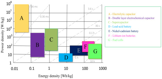
Figure 1.
Ragone plot.
The last-presented technology used for energy storage is electrochemical energy storage, to which further part of this paper will be devoted. Electrochemical energy storage is one of the most popular solutions widely used in various industries, and the development of technologies related to it is very dynamic. Various classifications of electrochemical energy storage can be found in the literature. It is most often stated that electrochemical energy storage includes accumulators (batteries), capacitors, supercapacitors and fuel cells [25,26,27]. The construction of electrochemical energy storage is very simple, and an example of such a solution is shown in Figure 2.
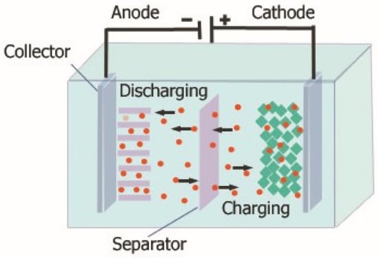
Figure 2.
Construction of an electrochemical energy storage.
As can be seen, typically electrochemical energy stores consist of two electrodes (anode, cathode). The anode is an electrode, where oxidation typically occurs, while the cathode is an electrode, where reduction occurs. These electrodes are made of materials of high electrical conductivity, such as metal or carbon, coated with appropriate chemicals. Both cathodes are placed in an electrolyte, which is a chemical substance that acts as an ion conductor between the anode and the cathode. It can be a liquid or a gel containing suitable salts or acids. The electrolyte allows the flow of ions between the two electrodes, which is essential for electrochemical reactions to take place. In addition, it can be seen that in the structure of the considered storage devices, there is also a separator that prevents direct contact with the electrodes and the formation of a short circuit. The separator must be ion-permeable to allow a charge to flow between the electrodes yet must also provide electrical insulation.
The principle of operation of electrochemical energy storage devices is based on the formation of a chemical reaction between the electrolyte and the electrodes contained in it. Then there is a shortage of electrons on one of the electrodes and an excess on the other. This allows chemical energy to be converted into electrical energy. When charging a battery, an electric current flows through both the electrodes, causing ions from one electrode to flow through the electrolyte and be stored on the other electrode (usually the cathode). When discharging, the process is reversed: the chemicals on the cathode are decomposed and the ions flow back through the electrolyte to the anode, where they are transferred out of the devices in the form of electric current.
As can be seen from the information presented in Figure 1, there are many electrochemical energy storage technologies; however, the choice of the appropriate solution depends on the needs and the application system. It is observed that fuel cells currently have the highest specific energy value and thus the longest energy storage time. Moreover, it is known that fuel cells can store energy for up to 10 h, but their specific power is at the level of 100 W/kg.
Supercapacitors store energy in an electric field between two carbon electrodes. The basic electrical properties of supercapacitors are similar to conventional capacitors used in the electrotechnical or electronic industry [27].
On the other hand, a fuel cell converts hydrogen from the gas tank and oxygen from the atmospheric air into water and generates current through an electrochemical process. The reaction occurring in this process is reversible if appropriate systems are used, such as redox flow accumulators [27,28].
The most important parameters of electrochemical energy storage are:
- Electrical capacity, which characterizes the ability of energy storage devices to store energy. It is defined as the amount of electric charge expressed in [Ah] that can be taken from a fully charged device by discharging it at a temperature of 25 °C with the specified current. In the case of accumulators, it is assumed that the accumulator is discharged with a 20-h rated current (in the literature, capacities are also given for 10, 5-h or 1-h currents), until the appropriate final voltage is obtained (typically 1.75 V/link) [29]. For example, the electrical capacity of a battery depends on many factors, such as:
- the method of battery discharge (applied currents),
- the degree of sulphation of the boards resulting from aging processes and the method of exploitation,
- the environment—primarily the influence of temperature [29,30]. The rated current that affects the electrical capacity of the group of energy storage units under consideration is defined as the quotient of the rated electrical capacity and the discharging time resulting from this capacity. Typically, for batteries this current corresponds to 5% of the nominal capacity given in Ah [29].
- Rated voltage. The value of this parameter depends, for example, on the number and type of cells connected in series inside the battery.
- Internal resistance. This depends primarily on the type of the electrolyte, the design and size of the electrodes and the distance between them, the state of charge of the energy storage, the temperature and its age (in the case of batteries).
- Energy density. This parameter refers to the amount of energy that an energy storage system can store per unit of mass or volume. This is an important parameter when evaluating the efficiency of energy storage, as it indicates how much energy can be stored in a given system, taking into account its weight or volume.
- Energy storage power density—refers to the ability of an energy storage system to supply or consume energy at a given time. It expresses how quickly energy can be stored or released relative to the mass or volume of the energy store.
- Time and number of charging/discharging cycles, which determine the time needed to deliver energy to the storage (charging) device or to take it from the storage (discharging) device and how many times the energy storage can be charged and discharged.
The quantity defining the battery and the fuel cell as a source of voltage is the electromotive force. This is defined as the potential difference across open battery terminals. This parameter is characteristic of each battery design, and its value is given for a single cell. The value of the considered parameter depends on the battery charge level, environmental factors, and primarily on temperature. According to the literature, the electromotive force is an increasing function of temperature and the level of charge of the battery [29].
3. Accumulator and Battery Energy Storage Technologies
As mentioned earlier, batteries are the oldest form of electricity storage. They store electrical energy in a chemical form, and their properties depend primarily on the type of the materials used, manufacturing processes, and operating conditions [27].
Batteries have the ability to respond to power demand within milliseconds and have very low stand-by losses. In addition, depending on the application and operating conditions, they can achieve high energy efficiency. Batteries in stationary applications rival flywheels, supercapacitors and magnetic energy storage systems [26,27].
Batteries consist of one or more cells, depending on the type and capacity of the cell. Battery cells are usually connected in series or parallel to increase voltage or capacity of the battery. For example, common car batteries often consist of six cells connected in series, giving a voltage of about 12 V, while larger batteries, such as those used in emergency power systems or renewable energy sources, may consist of tens or hundreds of cells [29].
There are many types of batteries used to store energy commonly used in the power electronics, automotive industry, etc. These technologies can be divided into classic and modern. In the further part of this section, these technologies are described, taking into account their division.
3.1. Clasic Battery Energy Storage Technologies
To the group of classic batteries belong:
- -
- lead-acid batteries, discussed in Section 3.1.1,
- -
- lithium-ion batteries, described in Section 3.1.2,
- -
- nickel–cadmium batteries, described in Section 3.1.3.
3.1.1. Lead-Acid Batteries
Lead–acid batteries are the most popular and cheapest solution for energy storage [29,31]. In lead–acid batteries, the electrolyte is an aqueous solution of sulfuric acid H2SO4 with a concentration of 37.5%, while the material used to make the negative electrodes is the so-called lead (a paste of ground lead pressed into a lead lattice), and, for the positive electrodes, lead dioxide PbO2 [32].
An unfavorable element of the considered batteries is the presence of the electrolyte in a liquid form, which results in leaks or losses of the electrolyte due to its construction. As a consequence, it is necessary to ensure the maintenance of such a battery by electrolyte replenishment [32].
In the case of the group of the considered batteries, they typically occur in two forms containing three cells (the nominal voltage of the battery is 6 V) and 12 V batteries containing six cells.
In turn, in order to improve the properties of the considered batteries related to the problems resulting from the use of a liquid electrolyte, they are made as maintenance-free SLA (Sealed Lead Acid) or VRLA (Valve-Regulated Lead–Acid—control valves) [33,34]. They are produced in two technologies, i.e., as gel batteries (in which, after mixing a liquid solution of sulfuric acid with silica, a gel-like mass is formed, acting as an electrolyte) and as AGM batteries (Absorbed Glass Mat, in which the electrolyte is absorbed in a separator made of a porous glass fiber mat) [35]. Due to the need to reduce the operating costs of this type of batteries and the need to eliminate electrolyte losses, maintenance-free batteries are currently the most often used [29,32].
Figure 3 shows the dependence of the charging efficiency of the considered battery on the state of charge (Figure 3a) and the charging current (Figure 3b).
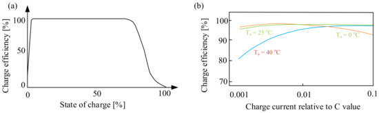
Figure 3.
Dependence of the charging efficiency on the state of charge (a) and the charging current (b).
As can be seen (Figure 3a), the battery charge efficiency decreases when the battery is fully charged. This is caused by the fact that when the battery is fully charged, the supplied energy resulting from the flowing current is partly converted into heat and partly causes water electrolysis. However, it is worth noting that the charging efficiency is already reduced when charged to about 75%. This means that special attention should be paid to the final charging phase. This applies in particular to the battery version with a sealed housing.
In turn, from the characteristics presented in Figure 3b, it can be seen that the dependence of the charging efficiency on the battery charging current in relation to the capacity C depends significantly on the ambient temperature, Ta. Significant changes are observed for the ambient temperature Ta = 40 °C. At the considered value of temperature, the charging efficiency is the lowest for the charging current relative to C, equal to about 0.001. With an increase in this ratio, the efficiency increases, reaching the highest value at the charging current relative to C equal to 0.1. In the case of the ambient temperature Ta = 25 °C, it can be seen that the charging efficiency does not significantly depend on the charging current, while the value of the considered parameter decreases for the current to the capacitance ratio equal to 0.1 at the ambient temperature Ta = 0 °C.
In addition, according to paper [29], the rated temperature of open and maintenance-free lead–acid batteries is 25 °C. It was indicated that the recommended operating and storage temperature range for these batteries is 15–25 °C. The operation and storage of batteries at elevated temperatures significantly reduces their life. Operating temperatures higher than the recommended (25 °C) causes the destruction of the active material of the electrodes and chemical degradation of the electrode plates, which results in shortening the battery life and reducing its capacity.
3.1.2. Lithium-Ion Batteries (Li-Ion)
The first research about lithium-ion batteries was initiated in the 1970s during the oil crisis by John B. Goodenough, who worked at the IBM Research Laboratory in New York. Together with the British M. Stanley Whittingham and the Japanese Akira Yoshino, he was awarded the Nobel Prize in Chemistry in 2019 [36].
In the literature, many types of lithium batteries, such as lithium-ion batteries or solid-state lithium batteries are described [37], but in this section and the following sections only the most popular solutions will be discussed.
Lithium-ion batteries [37] are currently one of the most advanced mass-produced electrochemical energy storage devices. Like all the devices of this type, they consist of two electrodes, an anode and a cathode, separated from each other by a separator with an electrolyte.
In a lithium-ion battery, the anode is made of carbon or graphite, while the cathode is made of metal oxides, such as cobalt oxide, nickel oxide, manganese oxide or mixtures thereof. The electrodes are separated by a separator saturated with a lithium-salt solution. A liquid, gel or solid conductive polymer may be used as the electrolyte. Most lithium-ion cells contain a liquid electrolyte with a dissolved lithium salt, such as LiPF6, LiBF4 or LiClO4. The solvent is usually a mixture of organic carbonates [36,38].
The considered devices have a relatively high operating voltage, ranging from 2.5 to 4.1 V, while their rated voltage is 3.6 V [39]. The specific energy of Li-ion cells available on the market is even 270 Wh/kg [40]. The maximum values of the discharging current can reach 5 C, although in most cases it is not recommended to exceed this current above 1–2 C [40]. They also have the highest efficiency among electrochemical cells, i.e., the ratio of the energy obtained during discharge to the energy supplied while charging, which usually exceeds 90% (depending on the size of the load) [40]. The self-discharge rate of Li-ion cells is very low, which means that they can be stored for several years without a significant loss of capacity. They do not show the memory effect either, and the temperature range in which they can work is very wide, from −20 °C to 65 °C [41].
These batteries are also characterized by a non-linear characteristic of the discharge voltage as a function of the state of charge, and a significant influence of temperature on their properties is observed [40]. An important parameter of the considered battery is the open-circuit voltage. An exemplary waveform of this voltage from paper [40] for the charging and discharging state of the considered battery is shown in Figure 4 [40].
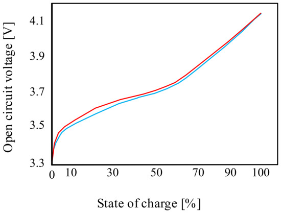
Figure 4.
Example of an open-circuit voltage waveform for the lithium-ion cell.
As can be seen from the characteristics presented in Figure 4, both the charging and discharging curves are non-linear for SOC < 70%. At the indicated state of charge (SOC), the open-circuit voltage value is approximately 3.7 V. For SOC > 70%, the charging-discharging curve is linear. When fully charged, the open-circuit voltage is approximately 4.1 V.
On the other hand, Figure 5 presents the typical charging and discharging characteristics of lithium-ion batteries.
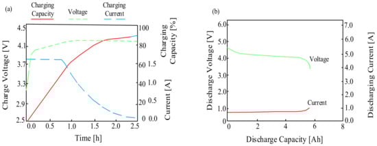
Figure 5.
Typical characteristics of the lithium-ion battery (a) charging, (b) discharging.
As can be seen when the considered battery is charging, good electrical properties are observed. During the charging process, the charging capacity gradually increases while maintaining a constant charging current. When the voltage reaches its maximum, the charging current decreases exponentially. On the other hand, when discharging, the voltage and current remain almost constant for the load, although there is a slight decrease and an increase in the voltage and current values, respectively, up to the level of the minimum acceptable cell capacity, which is set by the manufacturer as the end-of-charge voltage.
The considered cells are currently widely used in consumer electronic devices all over the world [40,41]. Compared with lead–acid batteries, they are also characterized by high energy density and are much lighter, which also determined their use in electric vehicles [42]. A significant disadvantage of this group of devices is a flammable electrolyte, which means that the process of their production and operation requires the provision of the appropriate test and protective conditions.
Nevertheless, as mentioned earlier, these batteries are widely used and widely described in the scientific literature. The studies focus on improving their properties, e.g., by using graphene carbon as an anode or other previously mentioned materials [43], or they focus on the effect of temperature on their parameters [40,44]. In turn, some other papers are devoted to the formulation of models for the analysis of their properties [45].
For example, in [45], charging and discharging simulations of a ternary lithium-ion battery were carried out. Changes in the capacity of the considered battery at different values of the ambient temperature Ta were analyzed. The results of the investigations carried out and presented in [45] show that at the ambient temperature Ta of −60 °C, after 4000 charging and discharging cycles, SOC (State of Charge) is about 91.8%. At the ambient temperature Ta = 25 °C, SOC is about 86%. It was noted that with an increasing temperature, SOC of a lithium-ion battery gradually decreases. Based on the obtained results, it was found out that a low temperature affects the activity of the internal chemical materials in the lithium-ion battery, which is not conducive to normal charging and discharging.
In turn, paper [46] discussed the influence of temperature on parameters of the charging process and the durability of lithium-ion cells charged with the use of the Quick Charge technology. The currently used fast-charging techniques and aging processes occurring in the considered cells were described. Cell parameters were measured during the charging process at two different temperatures. The tests were carried out using a Sony Xperia X Compact smartphone, which contained a Sony US395292H5 lithium-ion battery. The research shows, among other things, that the charging time at 40 °C was significantly longer than the charging time at 20 °C. During each of the attempts to charge the device, the temperature of its battery increased. In the case of using the Quick Charge technology, the increase in the temperature was bigger: the temperature increased by 14.6 °C and by 19.5 °C compared with the ambient temperature of 20 °C.
3.1.3. Nickel–Cadmium Batteries (Ni–Cd)
Nickel–cadmium (Ni–Cd) batteries are the batteries that are widely used in the automotive industry, in electric vehicles, aviation, emergency systems (lighting), and military equipment (radio communication). Like all the batteries discussed earlier, they contain two electrodes, of which the anode is made of metallic cadmium, while the cathode is made of nickel oxides. The electrolyte in such a battery is a 20–30% aqueous solution of potassium hydroxide (KOH) or sodium hydroxide (NaOH) [47]. Ni–Cd batteries are characterized by an energy density of about 50–60 Wh/kg, and the nominal voltage of one cell in such a battery is 1.2 V. They are also characterized by a high number of charging and discharging cycles, from several hundred to several thousand, depending on the design. The charging current of this type of batteries is from 0.1 C to 1 C, and the discharging current can reach up to 5 C. They are also characterized by stable operation in a wide temperature range, from −50 °C to even 70 °C [48,49].
An important advantage of the considered batteries is their high resistance to shocks and vibrations as well as low costs. The disadvantage is the toxicity of the cadmium anode, which limits the use of this type of battery in some countries around the world. However, scientific research is also being carried out focusing on the problem of recycling and the recovery of cadmium from the considered batteries [50].
As in the case of the energy storage technologies discussed earlier, work is still being carried out to improve the properties of these batteries, the way they are charged, etc., as seen in numerous papers available in the scientific literature.
For example, in [51] it was shown that fast charging improves the efficiency of this process. It was noticed that with a charging current of 1 C, the efficiency of a standard NiCd battery is about 91% and the charging time is about one hour (66 min). In the case of standard charging, the efficiency of the considered battery decreases to 71%, which extends the charging time to about 14 h at a current of 0.1 C. It was noted that at 70% of the total charging time, the efficiency of NiCd is close to 100%. It was also noted that NiCd batteries designed for fast charging can be charged with a current that is several times higher than the typical charging current given in the datasheet, without a significant increase in temperature.
Figure 6 shows the characteristics of the cell voltage, pressure and temperature during the charging process of the considered battery.
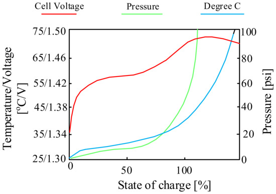
Figure 6.
Charging characteristics of the NiCd cell.
As can be seen (Figure 6), the charging process proceeds correctly to SoC of 70% of the battery’s total charge. Above the mentioned value of the state of charge of the battery, it can be seen that its efficiency decreases. The cells begin to produce gases, the pressure inside the battery increases and a rapid increase in temperature is observed. To reduce the “stress” of the battery, some chargers reduce the charging current after exceeding 70% of charge.
On the other hand, Ref. [52] presents the investigations of the influence of variable excitation signals on the state of charge and lifetime of rechargeable nickel–cadmium batteries used in aviation. The investigations were carried out in the current frequency range from 0.1 kHz to 1 kHz. The method of monitoring the charging process using impedance spectroscopy was used for the investigation. A linear correlation between voltage and capacity was observed as long as overcharging and deep discharging of the considered battery was avoided. The memory effect of the used nickel–cadmium battery was also investigated and it was stated how this effect can be minimized. An illustrative characteristic contained in the cited paper related to the aforementioned memory effect is shown in Figure 7.
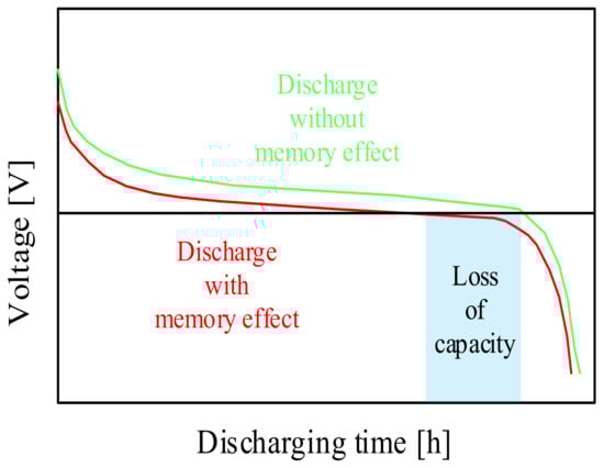
Figure 7.
Qualitative discharging characteristics of the memory effect.
As can be seen in Figure 7, the considered battery type remembers the previous state of charge and causes an undesirable early voltage drop on the next charge. Due to the formation of crystals on the anode, the stored energy becomes available only at a lower voltage than the initial voltage.
3.2. New Battery Energy Storage Technologies
To the group of new batteries belong:
- -
- lithium–polymer batteries, discussed in Section 3.2.1,
- -
- lithium–sulfur batteries, described in Section 3.2.2,
- -
- metal–air batteries, described in Section 3.2.3,
- -
- sodium–nickel-chloride batteries, described in Section 3.2.4,
- -
- nickel–metal-hydride batteries, described in Section 3.2.5,
- -
- sodium-ion batteries, described in Section 3.2.6,
- -
- sodium–sulfur batteries, described in Section 3.2.7,
- -
- vanadium batteries, described in Section 3.2.8,
- -
- zinc–bromine batteries, described in Section 3.2.9,
- -
- zinc-ion batteries, described in Section 3.2.10.
3.2.1. Lithium Polymer Batteries (Li-Polymer)
Lithium polymer (LiPo) batteries (cells) are the next generation of lithium-ion cells. The principle of operation and construction of lithium polymer batteries (illustrated in Figure 8) is the same as in the case of lithium-ion batteries. This cell contains a polymer electrolyte, which is made of semi-solid (gel) polymers of high conductivity. These batteries provide higher specific energy than other types of lithium batteries and are used in weight-critical applications such as mobile devices, radio controlled aircraft and some electric vehicles [53].
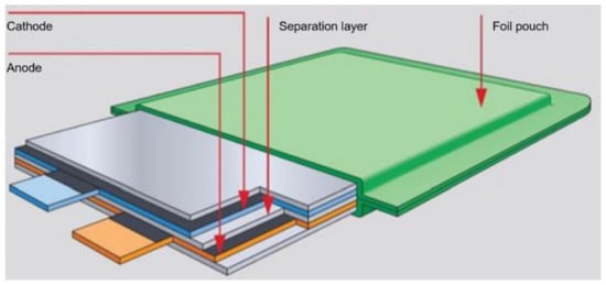
Figure 8.
LiPO battery pouch construction.
In LiPo, a polymer separator is used, which also contains an electrolyte. In addition, the polymer separators can have an additional function, i.e., they can shut down the battery if it becomes too hot when charging or discharging. Separating separators are multi-layer constructions, which include at least one polyethylene layer that can stop the current flow in the event of too high a temperature increase, and at least one polypropylene layer constituting a mechanical support for the separator [54].
Typically, the considered batteries have a maximum charging voltage of 4.2 V for charging, and for special cells up to 4.35–4.4 V, a maximum charging current of 1 C, and for larger cells 0.5 C, and a temperature range that ensures the correct operation from 0 °C to +45 °C.
On the other hand, in the case of discharge: they are characterized by a minimum voltage of 3.0 V, a discharging current of up to 1 C (in some cases 2 C) and a temperature range guaranteeing the correct operation from −20 °C to +60 °C (with appropriately reduced voltage levels and capacitances at low temperatures) [55].
Typically, they also have a capacity of 80% after 500 cycles of charging and discharging at a current of 0.5 C [55]. The energy density of lithium-polymer batteries reaches values up to about 200 Wh/kg, and their capacity varies depending on the design and the desired performance, from a few mAh to over 10 Ah [56]. It is also worth noting that they can operate at much higher loads, depending on the type of cell, even at temperature up to 30 °C [56].
Examples of the charging and discharging characteristics of the considered Lipo cells are presented in Figure 9 [57].
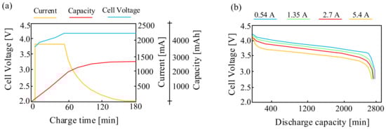
Figure 9.
Charging (a) and discharging (b) characteristics of the LiPO battery.
As can be seen in Figure 9a, the time necessary to charge such a cell with a charging current of 1.4 A is about 150 min. It is also observed that in the case of the considered cell, after 180 min, when the cell is fully charged, the voltage at its terminals increases by about 10%. In turn, it can be seen from Figure 9b that with an increase in the cell discharging current, the voltage on the considered cell decreases. It is also observed that with an increase in the capacity from 400 mAh to 2800 mAh of such a battery, the voltage at the terminals of the considered battery decreases by more than 25%.
As in the case of lithium-ion batteries, lithium-polymer batteries are also very popular and research is being carried out on the influence of selected factors on their properties.
For example, in [58], the design and the operation of a hybrid parallel drive designed for use in unmanned aerial vehicles are discussed. The appropriate investigations of different types of batteries were carried out and the obtained results were presented. The investigations were also inducted for a lithium-polymer battery consisting of eight series-connected LiPO cells with a nominal voltage of 3.7 V and a capacity of C = 3.3 Ah. The battery pack for testing weighed 715 g. The investigations were carried out by discharging the battery with a constant current value in the range from 10 A to 60 A with a step of 10 A. Sample results presented in the cited paper are shown in Figure 10.
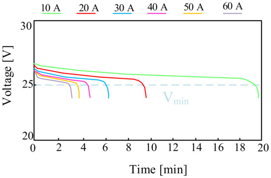
Figure 10.
Discharging characteristics of the LiPo cell with a nominal capacity of 3.3 Ah.
The relation presented in Figure 10 shows that with a continuous load of 40 A, the investigated battery can operate for about four and a half minutes. Increasing the operating time of the considered battery requires the use of a smaller load (10 A). The dashed line shows the minimum battery voltage value recommended by the manufacturer, i.e., 27.2 V.
In turn, in [59] a model of a lithium-polymer cell was proposed. The two-state modeling method that was improved was used in order to take into account the influence of temperature on the properties of the considered cell. The correctness of the model was verified by comparing the obtained measurement results with the results of computer calculations. The process of charging the cell with current, the values of which changed with a specific step, was also verified. From the characteristics presented in the cited paper, it can be seen that the time necessary to obtain a voltage of 4.2 V for the considered cell at the charging current is about 60 min, and the discharging time necessary to discharge the cell to 3 V with a 2 C current is about 25 min. In addition, it is indicated that the battery voltage decreases with time, although the period of stimulating the battery is periodic and one would expect that after 25 min the battery voltage will again reach the maximum value of 4.2 V. An increase in the temperature of about 3 °C after the mentioned time was also observed.
3.2.2. Lithium-Sulfur Batteries (Li-S)
The lithium-sulfur (Li-S) battery also belongs to the group of reversible galvanic cells. In the case of the considered battery, the cathode is made of sulfur.
The advantage of using sulfur for the construction of the cathode of the Li-S battery is its common occurrence, and thus the low cost of production. The disadvantage of this solution is low electrical conductivity of sulfur 5 × 10⁻³⁰ S/cm at 25 °C [60]. However, this property can be improved by using a carbon coating on the cathode made of sulfur. Carbon nanotubes can also be a solution to this problem [61]. Carbon materials provide a much more effective electron conduction path and structural integrity, but the production of carbon nanotubes is very expensive, which makes them unprofitable and unattractive for commercial and consumer applications [61].
One of the problems occurring in lithium-sulfur cells is also the phenomenon of lithium absorption by the cathode made of sulfur. Then volumetric expansion of the LixS complex occurs, so that the predicted increase in Li2S volume is almost 80% of the initial volume of sulfur [60,62]. This causes high mechanical stresses on the cathode, which is the main reason for its rapid degradation. This process also reduces the contact area between carbon and sulfur and prevents the flow of lithium ions to the carbon surface [60].
The lithium-sulfur cell is characterized by a very high energy density (350 Wh/kg). Due to the low lithium density and moderate sulfur density, Li-S batteries are relatively lightweight, with a density of about 1 g/cm3 [60,63].
Li-S batteries have a much larger capacity than typical lithium-ion batteries, and their production cost is lower when sulfur is used for the construction of the cathode, which is widely available and therefore a cheap raw material. However, an unfavorable feature of these cells is the strong dependence of their capacity on the number of charging and discharging cycles [60].
Due to the high capacity of the lithium-sulfur cell and the non-linear discharging and charging curve of this cell, the operation of such a cell must be supported by a system containing a microcontroller supervising the parameters of this cell and various safety circuits (e.g., output voltage regulator), ensuring the control of the state of the cell and protection against rapid discharge [60,64].
Typically, lithium-sulfur cells are characterized by a nominal voltage of 2.1 V, an energy density of about 350 Wh/kg, a maximum number of charging and discharging cycles: 1000, and a temperature range of the correct operation from −20 °C to 60 °C. An example of the discharging characteristics of a lithium-sulfur battery presented in [60,65] is shown in Figure 11. In the considered case, it was assumed that the battery contains 6 cells connected in series. In addition, the differences between the voltages of the connected cells and the resistance of the connections between them were omitted. The electromotive force of the battery is 12.6 V. It was also assumed that the starting current at the working voltage measured on the battery is equal to 6 V is 100 A.
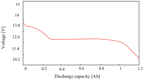
Figure 11.
Example of the Li-S battery discharging characteristics.
The characteristics presented in Figure 11 show that above the voltage of 12.5 V, the value of the current decreases from 0.3 A to 0, which can be delivered by the considered battery. On the other hand, below the indicated voltage value, the current value that this battery can deliver increases, obtaining a current of approx. 1.2 A at a voltage of approx. 10 V [60]. Li-S cells are a promising solution that could be used in many industries, especially in the automotive industry. However, a significant challenge related to the development of this technology is the short lifetime of Li-S cells. This problem is the starting point for scientific investigations conducted in the world aiming at improving the properties of the considered cells.
For example, the paper [66] presents the investigations concerning the influence of temperature on the life of a lithium-sulfur cell. The investigations were carried out using “pouch” cells with a capacity of 19 Ah and they showed that the lifetime and efficiency of lithium-sulfur cells significantly depend on the temperature, which can be seen in Figure 12.
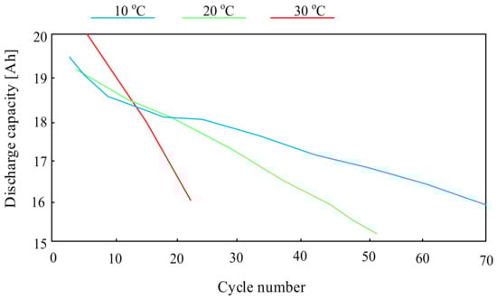
Figure 12.
Dependence of the Li-S battery capacity on the number of charging and discharging cycles.
As can be seen, the highest number of cell charging and discharging cycles were obtained at an ambient temperature of 10 °C. A three-fold increase in this temperature reduces the number of charging and discharging cycles of the considered battery by more than 60%.
In turn, the paper [67] presents a lithium-sulfur model, thanks to which, at the design stage, chemical modifications can be made that can improve the lifetime and parameters of the considered technology. The correctness of the model was verified by comparing the obtained calculation results with the results of laboratory tests. An exemplary characteristic describing the dependence of the battery life (SoH) on the number of charging and discharging cycles is presented in Figure 13.
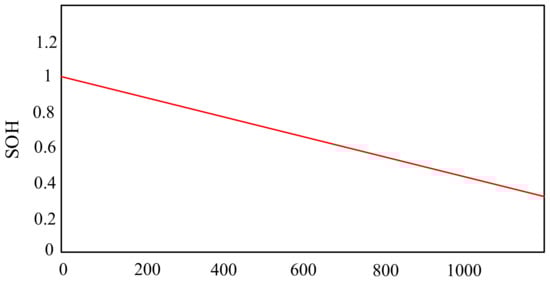
Figure 13.
State of Health (SoH) evolution through cycling.
From the characteristics presented in Figure 13, it can be seen that the efficiency of the battery decreases with an increase in its charging and discharging cycles. It is observed that after 400 cycles the efficiency of the considered battery is 80%. However, with the number of cycles equal to 1200, its efficiency is only 40%.
3.2.3. Lithium-Polymer-Iron Batteries (LiFePO4)
Lithium-polymer-iron cells are another variety of lithium cells. These cells have an energy density of 90 to 140 Wh/kg, a nominal voltage of 3.3 V, and a nominal capacity of 50 Ah to 200 Ah (depending on the manufacturer and the model). The maximum charging current is usually from 0.5 C to 1 C, and the maximum discharging current is usually from 1 to 3 C. In the case of the considered cells, the number of their charging and discharging cycles is in the range from 1000 to 5000, and the permissible operating temperature is usually from −20 °C to 60 °C. On the other hand, the weight of such a cell usually ranges from 1.5 kg to 4 kg (depending on the manufacturer and the model) [58].
LiFePO4 cells do not tend to ignite, explode or self-ignite as a result of mechanical damage or overheating; therefore, they are safe to use. For this reason, they are widely used in the automotive industry, military industry, medicine, etc.
As in the case of the previously discussed various types of lithium cells, many papers in the literature are devoted to the investigations improving the properties of lithium-polymer-iron cells.
For example, papers [68,69] present experimental and numerical studies of the thermal efficiency of a LiFePO4 (LFP) pocket battery in a discharging current range of 1 C to 5 C at an ambient temperature of 23 °C. The heat transfer coefficient of the battery was calculated for each of the mentioned discharging currents under natural convection conditions, and the temperature distribution on the surface of the battery was investigated. The results of the investigations showed that the maximum and average battery temperatures were 52.2 °C and 50.1 °C, respectively, and the maximum temperature difference on the surface of the battery was 6.7 °C. In addition, it was noted that the homogeneity index determined for the temperature on the battery surface is 0.147 at a discharging current of 5 C. It was found out that natural convection cooling is not sufficient for batteries at high discharging currents.
In turn, in [70], it was pointed out that superposition in alternating current circuits (e.g., in systems of renewable energy sources and electric vehicles) exposes the considered batteries to high-amplitude pulsed currents. This causes them to experience shallow charging–discharging cycles or micro-cycles, which results in a significant increase in the charging current and, as a result, may reduce the lifespan of the cell in question. In order to check the influence of high-amplitude alternating currents on properties of the battery, the research using the LiFePO4 cell was presented in the cited paper. The battery was excited by an alternating current of a frequency range from 0.1 Hz to 1 kHz. The considered cells were cyclically charged and discharged for about 200 days, which reflects the actual application systems in which these cells are used. The obtained results showed that as long as the AC current induces a voltage oscillation that remains below the calculated threshold polarization potential, the lifetime of the investigated cells does not change significantly. It was noticed that for high-frequency alternating current, a significant number of micro-cycles is effectively filtered by the double-layer capacitance of the battery. However, for a low-frequency alternating current, which is not as effectively filtered, an increase in the charging current caused by micro-cycles is observed, which causes accelerated wear of such a battery.
In turn, in the previously cited paper [58], the properties of lithium-polymer-iron cells were also considered, and the obtained results are presented as an example in Figure 14. This figure shows the discharging characteristics of a LiFePO4 cell with a nominal capacity of 2.3 Ah.
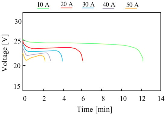
Figure 14.
LiFePO4 cell discharging characteristics.
From the characteristics presented in Figure 14, it can be seen that with an increase in the discharging current from 10 A to 50 A, the discharging time of the investigated cell decreases by six times.
3.2.4. Metal–Air Batteries (Metal–Air)
Metal–air batteries were invented in the early 19th century by Francis Thomas Bacon [71]. The anode may be made of metals, including alkali metals such as lithium, potassium, or sodium, or alkaline earth metals such as calcium and magnesium, certain metalloids such as silicon and aluminum, or transition elements such as iron and zinc. The electrolyte may be hydrated or non-hydrated depending on the type of the anode material. The second reducing electrode is air. Both electrodes in the considered cell are separated from each other by separators.
Metal–air batteries are a unique solution for energy storage because cathode oxygen is a widely available raw material from the environment and does not need to be stored [72].
The main advantage of metal–air cells is a very high energy density compared with other types of batteries, which ranges from 1000 Wh/kg to 3500 Wh/kg, depending on the type of battery and, above all, the anode material. Example values, e.g., the energy density depending on the anode material, are shown in Figure 15.
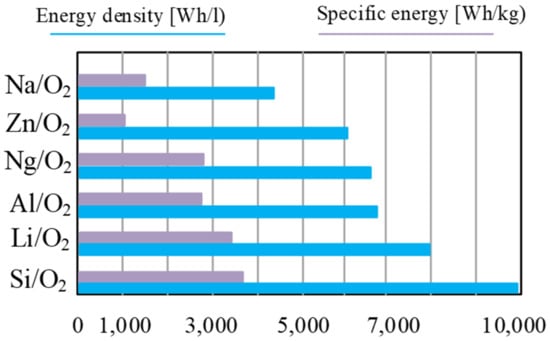
Figure 15.
Theoretical energy density and specific energy (including oxygen) of commonly researched metal–air batteries.
As can be seen from the data presented in Figure 15, the cells whose anode is made of silicon have the highest energy density, of about 3800 Wh/kg, while the lowest energy density is characteristic of the cells whose anode is made of zinc (about 1100 Wh/kg).
An important parameter of all the cells is the rated voltage, which in the considered case ranges from 1.2 V to 3.7 V. These cells are also characterized by a relatively long lifetime, defined as about 2000 charging and discharging cycles. The use of oxygen from the air surrounding the cathode is an additional advantage as it significantly reduces the cost and weight of the considered batteries. These batteries can be successfully used in the automotive industry (electric vehicles) and emergency power supply systems.
One of the main problems with metal–air batteries is their durability and lifetime. During the battery operation, metal oxide is consumed, which means that the battery gradually loses its capacity. However, new attempts are being made to increase the performance and durability of these batteries by using new cathode materials and electrolytes.
For example, in paper [73] the principle of operation of metal–air cells and the types of materials used for the construction of electrodes and electrolytes are discussed in detail. The paper points out that the use of aluminum for the construction of the anode is promising for this type of cell due to its high energy density, low weight, good recyclability, environmental friendliness, and low cost.
In turn, paper [74] presents a comparison of the properties of metal–air batteries, whose anodes are made of different metallic materials. Particular attention was paid, as in [73], to aluminum–air batteries. The comparison of the properties of various types of metal–air batteries presented in the cited paper is summarized in Table 1.

Table 1.
Electrochemical parameters of the different metal–air batteries in aqueous electrolytes.
As can be seen from the data in the table, the material used to build the anode of such a cell significantly influences its properties. For example, it is observed that the highest value of the rated voltage is characteristic for a cell whose anode is made of lithium and calcium, and the lowest value of this voltage is found in a cell with an anode made of iron. On the other hand, the specific capacitance at the anode per gram of the anode material is the highest, as in the previous case for a cell with a lithium anode, but the lowest value of this parameter is characteristic for a cell containing a zinc anode. It is worth noting that a high value of this parameter is also obtained for cells with an aluminum anode (AAB).
3.2.5. Sodium–Nickel-Chloride Batteries (Na-NiCl2)
Sodium–nickel-chloride (Na-NiCl2) batteries also called ZEBRA batteries (sodium–nickel-chloride battery) are a type of high-temperature secondary battery characterized by a high energy-to-weight ratio, high energy density and long life.
In ZEBRA batteries, the electrolyte is molten sodium chloride (NaCl) with the addition of lithium chloride (LiCl) or potassium chloride (KCl). The anode is made of a sodium metal, which is dissolved in the electrolyte, and the cathode is made of nickel powder.
ZEBRA batteries have an energy density of up to 150 Wh/kg. They are resistant to deep discharge and have a long lifetime, which means that they can be charged and discharged for many years without a significant loss of capacity [75].
The disadvantage of the considered batteries is their high operating temperature, in the range from 270 °C to 350 °C. In this case, it is necessary to use special insulating materials and adequate ventilation. These batteries, in comparison with the others discussed earlier, are also characterized by a complicated production process, which in turn leads to their high price [75,76].
Despite this, sodium–nickel-chloride batteries are considered a promising technology, e.g., due to their long lifetime, which is particularly important in such solutions as energy storage from renewable energy sources (solar panels and wind turbines). Currently, their market share is not as significant as the other previously described batteries [77].
Nevertheless, in the literature you can find a lot of papers devoted to these solutions, but these papers focus primarily on technological processes aimed at improving the properties of these batteries affecting the relationship between the technological process and the production price of such a battery. A hybrid solution is also proposed with the considered use of batteries and supercapacitors in automotive applications (electric vehicles) [78]. Therefore, this type of battery is not discussed in more detail in this paper.
3.2.6. Nickel–Metal-Hydride Batteries (Ni-MH)
As with Ni–Cd batteries, Ni–MH batteries have the so-called memory effect, which consists in reducing the capacity if the battery is charged before it is completely discharged. Therefore, it is recommended that Ni–MH batteries be fully discharged before charging.
The advantages of Ni–MH batteries include a higher energy density (60–120 Wh/kg) than in the case of Ni–Cd batteries; they are characterized by half the operating time on a single charge than Ni–Cd batteries. These batteries are safe for the environment and are characterized by the ability to operate in a wide temperature range, i.e., from −5 °C to 60 °C. The maximum charging current for this type of battery is 0.1 C, and the maximum discharging current should not exceed 2 C [79,80].
However, the significant disadvantages of this type of batteries are certainly lower capacity compared with lithium-ion batteries, high voltage instability when charging, which requires precise charging control, and a tendency to self-discharge, which means that they must be recharged every few months, even if not used.
Nickel–metal-hydride (Ni-MH) batteries have largely replaced nickel–cadmium batteries because they are greener and have a higher energy density. However, the principle of their operation and the scope of application are similar.
In these batteries, the cathode is made of nickel oxide (NiOOH) and the anode is made of a metal alloy, whose main components are cobalt and lanthanum. The electrolyte is an alkaline solution, usually composed of potassium hydroxide (KOH) or sodium hydroxide (NaOH) [81].
In the case of Ni-MH batteries as well, many papers are devoted to the study of their properties in various application systems [82].
For example, Ref. [82] presents an overview of the performance of lead–acid and nickel–metal hydride batteries during their operation in a single-phase UPS system. The performance of these batteries was evaluated based on the measured discharging curve and the state of charge. The obtained results of investigations showed that the NiMH battery is characterized by a higher capacity and constant discharging current and is more reliable in obtaining 12 V voltage at a minimum state of charge than the lead–acid battery. Examples of the characteristics from paper [82] presenting discharging curves for different values of discharging currents are presented in Figure 16.
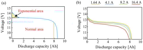
Figure 16.
Discharging curve of the NiMH battery at (a) 0.2 C and (b) different C-rates.
As can be seen in Figure 16a, according to the exponential region, the voltage of the NiMH battery decreases during the discharging process from 14.14 V to 13.02 V. Meanwhile, the total capacity of the considered NiMH battery is 6.73 Ah. In turn, from the dependence shown in Figure 16b, it can be seen that the higher the discharging current, the smaller the amount of electricity produced by the NiMH battery.
In addition, in [83] it was mentioned that at low ambient temperatures the maximum safe charging current is much lower than at room temperature. This is the reason for using control and measurement systems, e.g., detecting the temperature and reducing the charging current.
On the other hand, in paper [84] the constructed cylindrical NiMH cells of sub-C size were presented for investigating the efficiency of the considered cells in the conditions of long-term charging at elevated temperatures. The influence of the operating conditions on the efficiency of the cell and the type of materials from which the electrodes were made on this parameter was examined. The results of the investigations showed that NiMH cells have good properties when charged with a current of 0.2 C. The investigations show that the considered batteries retained their capacity and efficiency for one month. This proves that they can be successfully used as emergency power sources. However, the ambient temperature was also shown to be a problem for their proper operation. This means that the investigations should continue to improve the considered technology, first of all in terms of operation at high temperatures (above 50 °C).
3.2.7. Sodium-Ion Batteries (Na-Ion)
Sodium-ion (Na-Ion) batteries are batteries whose cathode is made of sodium oxide, sodium phosphate or sodium sulfate, and the anode is typically made of graphite or other carbon materials [85].
Na-Ion batteries have an energy density up to 160 Wh/kg. An important advantage of this battery is the ability to charge it to 80% of its capacity within 15 min at room temperature and maintain 90% of its capacity at −20 °C [86].
The nominal voltage of a single considered cell battery is 2.4 V; it is characterized by charging and discharging cycles in the range from 1000 to 5000, and it correctly operates in the temperature range from −20 °C to 60 °C [87].
An important advantage of this technology is the use of sodium, which is a widely available and cheap element, which in turn significantly reduces the cost of production of such a cell. In addition, Na-Ion batteries, compared with lithium batteries, are characterized by greater chemical stability and have a longer lifetime [88].
However, these batteries have some limitations. Due to the higher atomic mass of sodium compared with lithium, Na-Ion batteries have lower energy density than lithium batteries, which results in their lower capacity and a shorter operation time than lithium batteries. In addition, compared with lithium batteries, Na-Ion batteries have a lower efficiency, which means that they lose more energy during charging and discharging cycles [88].
Despite these limitations, Na-Ion batteries are considered a promising technology in the field of energy storage, especially in the applications related to renewable energy sources, such as wind and photovoltaic power.
They have become the subject of many papers and are widely described in the literature. In [89,90] it was indicated that sodium-ion batteries can be safely discharged down to 0 V. However, it was also pointed out that complete discharge of the considered type of battery may significantly reduce its life. Figure 17 compares the cycling stability of two Na-Ion cells: one cell was physically short-circuited for six months at 0 V, while the other was a primary cell that was not short-circuited.
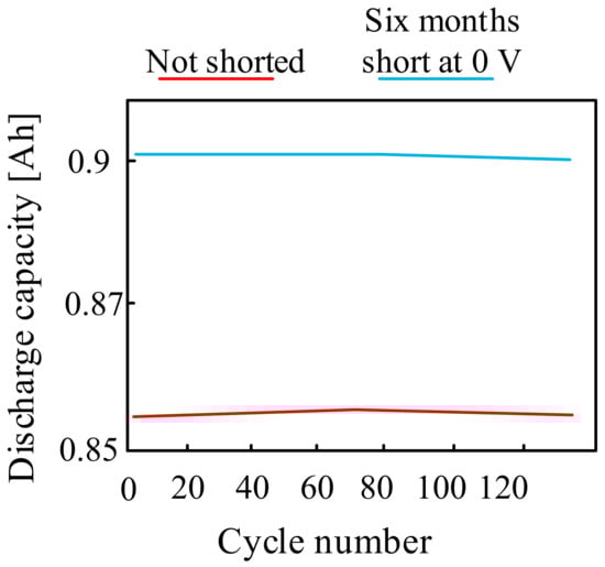
Figure 17.
Sodium-ion batteries discharge to 0 V characteristics.
As can be seen from the characteristics shown in Figure 17, the cyclic stability of the short-circuit cell at 0 V for six months turned out to be identical to that of the basic cell.
The potential of the use of sodium, and above all the reduction of the costs of its acquisition in relation to rare lithium, was noticed by the Chinese company CATL. This company was the first to introduce the commercial sodium-ion battery [91]. Although the batteries offered by the company still have a lower energy density than lithium batteries, they are used in some areas of transport. Despite the lower energy density of these batteries, CATL also introduced a mix-and-match energy storage solution, which is called the AB battery. This includes sodium-ion and lithium-ion cells in one system, with a specially developed algorithm that manages the energy flow, compensating for the lower density of the sodium-ion component and optimizing its efficiency [92].
Currently, apart from CALT, two other companies produce sodium-ion batteries: Faradion from the UK and Natron from the USA.
3.2.8. Sodium Sulfur Batteries (Na-S)
Na-S batteries are an attractive solution to operate in energy storage systems due to their good parameters and, above all, a very long service life of up to 15 years [60].
These batteries are characterized by a nominal voltage of one cell of about 2.58 V, an energy density of 100–120 Wh/kg, operating temperature range of 270–350 °C and a self-discharge rate of 3–5% per month [93,94].
Sodium–sulfur batteries have a typical cylindrical structure with a tube-shaped electrolyte 20–50 cm long, 1.5–3.5 cm in diameter, and wall thickness of about 1 mm [60].
The anode in a Na-S battery is usually made of metallic sodium or an alloy of sodium with other metals (e.g., nickel). The cathode is made of porous carbon or a nickel–chromium alloy coated with barium dioxide. Porous carbon is often used in smaller Na–S batteries, while nickel–chromium alloy is more often used in larger batteries. In general, in the considered battery, one of the electrodes is located inside the pipe and the other outside it [60].
In sulfur–sodium batteries, the electrolyte is a non-porous ceramic material shaped as a thin disc (for flat batteries) or a tube with one closed end used in cylindrical batteries [8].
The operation of the Na-S batteries is influenced by a number of factors, in particular: internal resistance, battery operation, operating temperature and depth of discharge [61]. According to paper [60], the internal resistance of the considered battery changes during the charging and discharging process depending on the depth of discharge and temperature. From the results presented in the cited paper, it can be seen that the internal resistance of the battery decreases when the temperature increases from 280 °C to 360 °C. At the end of the charging and discharging operation, there is a polarization effect, increasing this resistance. In [60], it was noticed that the internal resistance of the Na–S battery also depends on the number of charging and discharging cycles, which is presented in Figure 18.
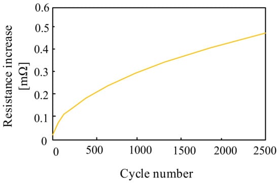
Figure 18.
Dependence of the Na–S cell resistance as a function of the number of charging and discharging cycles.
As can be seen from the dependence presented in Figure 18, the internal resistance of the battery increases with an increase in the number of charging and discharging cycles. An increase in the number of cycles from 500 to 2500 results in a more than four-fold increase in the resistance of the considered battery. This fact is of great importance, as it determines the remaining available peak power and the output voltage of the Na–S battery.
3.2.9. Vanadium Redox Batteries (VRB)
Vanadium redox batteries are a type of flow battery in which the electrolyte is a solution of vanadium sulfate. The anode in such a battery is usually made of platinum or titanium and the cathode is made of tungsten or stainless steel.
The advantages of vanadium redox cells include high durability, the possibility of complete discharge and the high output power reaching tens of kW, and fast charging by replacing the electrolyte. However, significant disadvantages of this technology [95] are low energy density and high costs associated with, among other things, the fact that it is a relatively new technology [96].
These batteries are characterized by a nominal voltage of a single cell of 2.3–2.4 V, energy density of about 30–50 Wh/kg, charging and discharging capability of over 10,000 cycles while maintaining over 80% of the nominal capacity. The typical recommended value of the charging current is from 0.3 C to 1 C [97]. Due to the fact that the considered technology is relatively new, it enjoys great interest and there is still much work being done to obtain faster and cheaper commercialization of VRB.
Paper [98] discusses the technology related to the production of VRB, describing in detail their genesis, existing solutions and current and future prospects for their use. The main original contribution of the paper is the discussion of the still missing in-depth review and the comparison of the existing publications on this technology. The cited paper also presents an economic analysis on the use of stored excess energy from a wind farm and its sale during the peak demand.
Paper [99] presents a review of the VRB technology that can be used in distributed energy networks to eliminate the disproportion between the energy produced by “unconventional sources” and its consumption. It was indicated that at the design level, the considered batteries combine the principles of operation of fuel cells and chemical energy sources with electroactive solid materials. It is especially noticeable during transitions between the forms of electrical and chemical energy in these devices when there occur oxidation and reduction of VRB-active electrolytes which are stored in separate tanks and pumped to the electrode chambers of the electrode membrane array (MEA) separated by a semi-permeable membrane. Such a method provides an important advantage of these devices over the other types of chemical energy sources, i.e., they provide a possibility of independently scaling the capacity of the energy stores.
In turn, paper [100] focused on the progress in the production of organic vanadium redox flow batteries with an aqueous electrolyte, including the molecular design and the impact of such a solution on battery performance. The authors indicated that the obtained results of investigations are promising. However, due to laboratory limitations, it is necessary to define models that will allow for a better understanding of phenomena occurring in batteries and will take into account the influence of external factors, such as temperature, on their properties.
3.2.10. Zinc–Bromine Batteries (Zn–Br)
In the ZnBr battery, the electrolyte exists in two forms, each of which is placed in a separate tank. The electrolyte on the anode side is a pure-water solution of ZnBr2, while the electrolyte on the cathode side additionally contains amines used to keep bromine in the solution during the charging process [95].
These cells are characterized by efficiency that does not exceed 75%. Their power density is the highest among flow batteries and reaches 1000 W/m2.
The assessment of the energy properties of the considered batteries has been carried out and described in the literature.
For example, paper [96] presents a technical, economic and environmental assessment of charging stations for electric vehicles powered by hybrid energy generation systems in three cities in Ethiopia. The investigations were carried out for lead, bromo–zinc and lithium-ion batteries. Using these three technologies, hybrid systems were proposed and compared in terms of size, economy, technical performance and environmental stability. The results presented in the paper prove that the system with charging stations for electric vehicles consisting of photovoltaic solar panels, a diesel generator and a ZnBr battery ensures the lowest net cost. Therefore, a wider application of the considered batteries should be considered.
On the other hand, in paper [95], the properties of commercially available batteries with parameters characteristic for micro-installations with a capacity of up to 10 kWh are presented. Exemplary characteristics included in the cited paper are presented in Figure 19. These are the discharging characteristics of the considered battery for several discharging currents of 10 A, 20 A, 30 A, 40 A and 50 A, respectively.
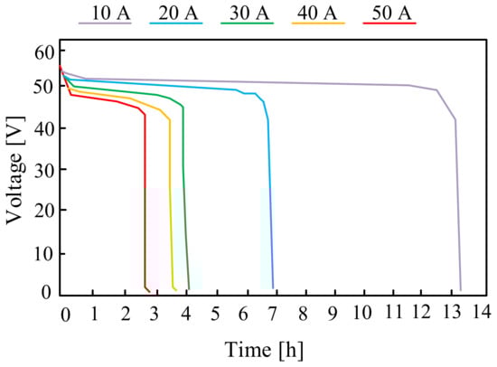
Figure 19.
Discharging characteristics of the ZnBr flow battery for different discharging current values.
3.2.11. Aqueous Zn-Ion Batteries (AZIBs)
A relatively new technology that is attracting more and more interest are aqueous Zn-ion batteries. In the literature, there are still few papers [100,101] devoted to this type of battery, and this is the reason why they are discussed here in very general terms.
Zinc used to build an anode with low potential and theoretically high capacity shows promising properties for energy storage, primarily in extensive solutions. AZIBs work on the principle of electrochemical oxidation and reduction of zinc. Zinc acts as the anode and manganese oxide (MnO2) is used as the cathode. An aqueous electrolyte solution is used to connect the anode and cathode, allowing ions to flow between them during the charging and discharging process [100].
The most important advantages of the considered batteries include high energy density, long lifetime and potential for recycling. They are also relatively safe because they do not use dangerous chemicals such as lithium. However, they also have some limitations. For example, they are relatively low-power, which means they are not the best solution for applications that require large amounts of energy in a short time. In addition, AZIBs require further research and technological development to improve their performance and increase their stability [101].
4. Supercapacitors
Supercapacitors are electronic components that are characterized by very high capacitance and power density. They are often called double-layer capacitors or ultracapacitors [101]. Similarly to the batteries discussed in the previous chapter, supercapacitors also contain electrodes, a separator and an electrolyte.
Due to the manufacturing technology, supercapacitors can be divided into three groups:
- EDLC double-layer supercapacitors manufactured, among others, by Elna Dynavap
- pseudocapacitors manufactured by, among others, Maxwell PCAP
- hybrids proposed, e.g., by Licap Technologies LC.
However, the most popular group of supercapacitors commonly used in industry are EDCL supercapacitors. Therefore, the next part of this section [102] will be devoted to these devices.
The principle of operation of the considered device makes use of the phenomenon of the Helmholtz double layer at the interface of two phases. This means that in the mentioned double layer there is a layer of electrons on the surface of the electrode and a shell of ions in the electrolyte. Starting the electrolysis process requires the existence of a limit voltage below which the electrolyte behaves as an insulator in a supercapacitor [101]. Thus, by supplying the supercapacitor with a voltage lower than the limit value, electrolysis does not occur. This results in the formation of a very thin non-conductive coating at the interface between the electrolyte and the electrodes. The small thickness of this coating and the use of metal electrodes coated with activated carbon allow the obtaining of very large active surfaces of the capacitor and a small distance of the accumulated charges, and thus very large capacitances.
Due to their construction, supercapacitors are characterized by low operating and breakdown voltages and a very low value of internal resistance. Typically, single supercapacitors are produced for a voltage in the range from 2 V to 2.8 V, while in hybrid solutions up to 5 V. Due to their attractiveness resulting from, among other things, large capacitances, in order to obtain a higher voltage value supercapacitors are connected in series in the so-called supercapacitor modules.
In addition to the supercapacitors mentioned above, such modules also contain systems that control the voltage on individual supercapacitors and their temperature. Due to significant capacitance tolerance values (of the order of ±20%) [101], when connected in series, the modules are also equipped with additional integrated voltage equalization systems (so-called balancers). The basic parameters of supercapacitors, as in the case of the already mentioned batteries, include: efficiency, which for supercapacitors is typically 90–94%; an energy density of 2–10 Wh/L; a power density of up to 15 kW/L; and the number of charging and discharging cycles, which is the highest among all the considered electrochemical energy stores and can be up to a million cycles. An important parameter of supercapacitors is also the depth of discharge, which is 75%, and self-discharge, which is 25% within 48 h, and a small percentage of self-discharge after this time [101].
Due to their properties, supercapacitors are widely used in industry. They are becoming more and more popular in hybrid vehicles and energy converter systems with an indirect DC circuit, where they play the role of an energy storage unit used to compensate for energy shortages in the event of supply voltage decays [101]. Supercapacitors are also increasingly used in renewable energy sources, where they are used to build hybrid energy storage systems.
The complexity of the processes taking place in supercapacitors and the influence of various factors on their properties, e.g., temperature, make them the subject of many research papers. For example, in paper [103], different materials used for the construction of the supercapacitor electrodes and the electrolyte were compared. First of all, it was pointed out that the type of material used for the construction of the electrodes is crucial in order to achieve the desired capacitance and fast-charging capability of this device. It was also noted that, in addition to the selection of the appropriate materials, the design and optimization of new configurations is a new area in the development of hybrid battery-capacitor systems.
In turn, in [103], it was indicated that supercapacitors, due to their properties, are usually used for fast charging and discharging cycles due to their exceptional efficiency in energy storage systems. It was pointed out that during charging/discharging cycles lasting from tens of seconds to ten minutes, supercapacitors are characterized by the best efficiency, which, in turn, is low for batteries in the considered time. It was also pointed out that due to the fact that the charging and discharging processes involve the flow of ions through the electrolyte, these devices cannot operate at such a high frequency as conventional capacitors. An example of the dependence of the frequency influence on the equivalent capacitance of a supercapacitor from the cited paper is shown in Figure 20.
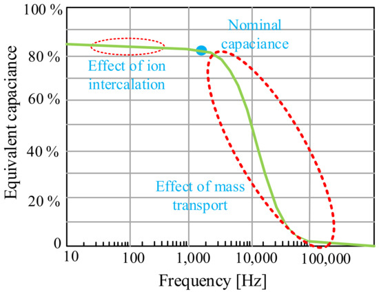
Figure 20.
Equivalent capacitance as a function of frequency.
From the dependence shown in Figure 20, it can be seen that the equivalent capacitance of a supercapacitor decreases with increasing frequency. It is observed that there is a cut-off frequency (which depends on the materials and the manufacturing process of the SC but is usually about 1 Hz) where the capacitance of the supercapacitor drastically decreases and the device ceases to be capacitive. As a result, these devices cannot be used to filter harmonic components of an electronic converter (several kHz). However, there are applications where it is necessary to filter intermediate frequencies, for example harmonics caused by diode rectifiers (hundreds of Hz). In the cited paper, it was also pointed out that the use of graphene for the construction of the supercapacitor electrode shifts the point of occurrence of the cut-off frequency to the range of several hundred Hz.
5. Fuel Cells
Fuel cells are devices classified as electrochemical energy sources that generate useful energy (electricity, heat) as a result of the chemical reaction of hydrogen with oxygen. The principle of the fuel cell was first observed during the electrolysis experiment conducted by William Grove in 1839 [104].
As in the case of other electrochemical energy stores discussed in Section 2 and Section 3, fuel cells also consist of two electrodes (cathode, anode) made of carburized paper with the addition of platinum, which are separated from each other by an electrolyte or a membrane. This electrolyte may be in a liquid or solid form [105].
The principle of operation of the fuel cell boils down to the direct conversion of the energy of chemical bonds of the fuel into electricity through chemical reactions, mainly oxidation. The chemical reaction taking place in the cell consists in splitting hydrogen into a proton and an electron at the anode, and then combining the reactants at the cathode. The result of this reaction is electricity, water and heat. In fuel cells, pure hydrogen or a mixture of hydrogen with other gases is most often used as fuel. The efficiency of fuel cells largely depends on the type of the fuel used [105]. In typical solutions, it assumes values in the range from 35% to 60%.
Currently, there are many types of fuel cells and in the literature you can find many criteria for their classification. The most popular is the classification of fuel cells due to the electrolyte used in them. In this case, the following cells are distinguished [105,106]:
- alkaline (AFC);
- with phosphoric acid (PAFC);
- solid oxide (SOFC);
- with molten carbonate (MCFC);
- with a proton exchange membrane (PEMFC).
- directly powered by methanol (DMFC)
In the alkaline fuel cell (AFC), the electrolyte is a water solution of potassium hydroxide. This cell is powered by hydrogen and oxygen. It is characterized by high sensitivity to carbon dioxide, which reduces the amount of hydroxyl group ions during a chemical reaction, and thus the degradation of such a cell. In order to avoid the destruction of the cell, an auxiliary carbon dioxide air purification system and pure oxygen supply are often used. In addition, the electrolyte used in these cells is corrosive, which shortens its life [104,105].
A phosphoric acid fuel cell (PAFC) contains liquid phosphoric acid (H3PO) as an electrolyte. The disadvantage of the electrolyte used is low conductivity at temperatures below 100 °C. The SOFC cell contains an electrolyte in the form of a solid, i.e., solid zirconium oxide (ZrO2) with an admixture of yttrium oxide (Y2O3). This cell is powered by a mixture of hydrogen and carbon monoxide and air. A temperature in the range of 800–1000 °C is required for proper operation of this cell [104].
The proton exchange membrane fuel cell (PEMFC) consists of two bipolar plates and a membrane electrode assembly (MEA). The membrane has a layered structure and blocks the flow of electrons and reactants between the anode and the cathode. It allows the flow of protons. It is a cell that does not require high operating temperatures. It works properly in the temperature range from 50 °C to 100 °C, which results in a faster response than in the case of high-temperature cells [105].
Direct methanol fuel cells (DMFC) are the latest technology compared with the previously mentioned cells. This cell is powered by methanol, and the oxygen contained in the air is the oxidant. There are two types of the considered cells, i.e., passive and active cells. The first ones consist of external components, i.e., a heat exchanger, a fuel supply pump, a circulation pump, a blower, a pressurized oxygen tank and a degasser, which transport the substrates and products of the reactions taking place [104,106]. The latter do not require the use of additional external devices. They consist of special layers and membranes that allow the penetration and permeation of the appropriate molecules [104]. The properties of the above-mentioned fuel cells are summarized in Table 2.
Table 2.
Comparison of fuel cells.
As can be seen from the data presented in Table 2, solid oxide fuel cells are characterized by the widest range of operation; however, compared with the other cells, they are characterized by low efficiency. Good properties compared with other cells are characteristic for the PEMFC cell due to higher efficiency, but also the ability to operate at lower temperature values in an equally wide range as the aforementioned cells.
Fuel cells are currently a technology that is constantly being developed and enjoys a lot of interest. In the literature, a lot of papers are devoted to this technology. For example, paper [107] presents a comparison of various fuel cells with other alternative energy sources. In the quoted paper, it was confirmed that the electricity conversion efficiency of most fuel cells ranges from 40% to 60%. It was also shown that among the currently available technologies, MCFC, SOFC and PEMFC cells are considered the most promising options for marine applications, and PEM cells were indicated as the direction of further development of fuel cells in the world.
It was also indicated that parameters that affect fuel cell performance include cell number, cell voltage, cell opening voltage, fuel cell efficiency, and a fuel utilization factor. The PEM cell was tested and a mathematical model of the power balancing system was proposed. It was noted that the actual voltage of the PEM cell is 0.868 V, and the opening voltage of the cell is 1.031 V, which significantly affects the efficiency of such a cell. It was also noted that this efficiency also depends on other factors. Figure 21 shows the dependence of cell efficiency on temperature and shows the Carnot limit (determining the efficiency of a heat engine); Figure 22 shows the dependence of cell efficiency on the cell voltage.
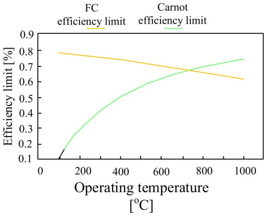
Figure 21.
Efficiency limit for a fuel cell and heat engines.
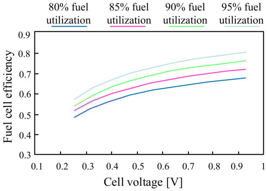
Figure 22.
Fuel cell efficiency at different voltage values and utilization factors.
It can be seen that the efficiency limit of the fuel cell is higher than the Carnot efficiency limit for an operating temperature from 100 °C to 750 °C. At 750 °C, the Carnot efficiency limit is equal to the fuel cell efficiency limit. However, as the operating temperature increases above 750 °C, the Carnot limit is higher than the efficiency limit of the fuel cell.
In turn, the characteristics presented in Figure 22 indicate that the higher the fuel utilization coefficient in the fuel cell, the higher the efficiency of the fuel cells. Each fuel cell has a utilization factor that corresponds to the output voltage of the cell. As the voltage of the fuel cell increases, the amount of hydrogen required will be less to achieve the same power output. In the case under consideration, the cell voltage is 0.72 V. Hence, the fuel cell efficiency will be between 40% and 55% at various fuel utilization factors. For a fuel utilization factor of 88%, the fuel cell efficiency is 53.53%.
6. Comparison of Batteries
In Section 2, Section 3 and Section 4, different technologies for storing energy are described in detail. All of them are characterized by different parameters, which means that they are used in different applications. Choosing the right energy storage solution depends on many factors, including the value of the energy to be stored, the time duration of energy storage (short-term or long-term), space, mobility, environmental issues, energy efficiency, cost, etc. Table 3 summarizes and compares electrochemical energy storage in terms of density energy and power, lifetime, and energy efficiency [92,108].
Table 3.
Properties of different technologies for energy storage.
As can be seen from the data presented in Table 3, supercapacitors are characterized by the highest power density and high (at the level of 95%) energy efficiency. However, these devices, compared with other technologies used for energy storage, have a low energy density, which may be on average 50 times lower than the value of this parameter for lithium-ion batteries or thermal or hydrogen technology. In turn, from the point of view of the service life, the highest value of this indicator, after supercapacitors, is characterized by magnetic technology and technology using a flywheel. Good parameters in the case of electrochemical technology are demonstrated by various types of lithium-ion batteries. It is also worth noting that these batteries are characterized by high energy efficiency similar to that of supercapacitors.
The advantages and disadvantages of the discussed technologies, which are summarized in Table 4, were also compared.
Table 4.
Advantages and disadvantages of electrochemical energy storage technologies.
As can be seen from the information presented in Table 4 and taking into account the data presented in Table 3, the choice of an appropriate energy storage solution is not obvious and requires a thorough technical, safety and environmental analysis, which will ultimately affect the cost of the installation of energy storage. Often, when choosing the right energy storage, apart from technical parameters, designers of various applications rely on well-known and commonly used solutions. If such a criterion were adopted, the choice would be limited to the use of lithium-ion batteries, lead–acid batteries, pumped-storage power plants or flywheel technology. However, each of the mentioned technologies differs significantly in terms of size, capacity, lifetime and, above all, the cost, which precludes the use of some of them.
Limiting our options to electrochemical energy storage, the best technical parameters among commercially available batteries are lithium-ion batteries due to their high energy and power density and efficiency; however, their service life depends significantly on the number of charging and discharging cycles. This technology is an expensive solution due to the use of lithium, which is a scarce raw material. In addition, improper disposal of the battery in question may lead to leakage of harmful substances and contamination of soil and water. In turn, a low-cost solution is the use of a lead–acid battery, but it is characterized by low energy density, low power density and the need for maintenance.
Figure 23 shows the applicability ranges of different electrochemical energy storage systems, taking into account the power rating system and the time during which this power can be released.
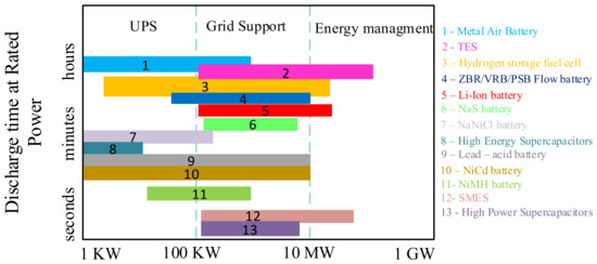
Figure 23.
Energy Storage Technologies by power capacity and discharging time.
Figure 23 shows that metal–air, NaNiCl, and NiCd batteries can be successfully used in UPS and T&D grid support systems, which require power ranging from 1 kW to even 10 MW (NiCd). In turn, it is observed that NaS cells are used in the aforementioned T&D grid support systems operating in the power range from 200 kW to 8 MW. In a similar power range, high-efficiency supercapacitors can also work in these systems. On the other hand, in power management systems up to 20 MW, lithium-ion batteries are typically used.
7. Final Remarks
The paper presents an overview of modern energy storage systems. It was indicated that each of the considered methods of storing this energy (supercapacitors, batteries and fuel cells) has specific features that determine the scope of its applications. Supercapacitors can be effectively used as storage facilities for fast charging and discharging. In turn, the production of clean energy is provided by fuel cells. Long-term energy storage is possible when using batteries.
As mentioned above, energy storage devices are used in many industries. Depending on the application (which specifies electrical parameters), budget, available space, etc., designers of various installations decide which solution and technology will be the best. Table 5 presents the examples of energy storage facilities in the world containing batteries made by different technologies. Table 6 shows the examples of energy storage devices used in electric vehicles of various brands.
Table 5.
Energy storage systems in the world.
Table 6.
Electrochemical energy storages technology in electrical vehicles.
As can be seen in the case of large energy storage facilities, different technologies with different configurations are used. The list presented in Table 5 shows that the Hornsdale Power Reserve system in Australia has the highest capacity, of 150 MW.
In turn, as the literature review shows, the batteries considered in this paper are also used in electric vehicles (Table 6) and in various types of portable devices. In the case of electric vehicles, it is observed that lithium-ion or nickel–metal–hybrid cells are typically used. In turn, lithium polymer technology dominates in portable devices. For example, in devices that are small in size and of unusual shapes, lithium polymer batteries are used [109].
This review present the current state of the art in the area of energy storage methods. This problem is important and topical, leading many scientists to conduct investigations in this area. More effective energy storage will be elaborated in near future for different applications.
In our opinion, all the considered electrochemical energy storages (batteries, supercapacitors, fuel cells) will develop independently due to the different scope of their applications. An important direction of their development will be the search for new materials that will be able to ensure a higher density of the stored energy and accelerate the charging process. A separate issue is the effectiveness and speed of methods of charging batteries, which is the subject of research conducted by numerous teams specializing in power electronic systems.
Author Contributions
Conceptualization, K.D. and K.G.; resources, K.D.; writing—original draft preparation, K.D. and K.G.; writing—review and editing, K.G. and K.D., visualization, K.D.; supervision, K.G. All authors have read and agreed to the published version of the manuscript.
Funding
This research received no external funding.
Data Availability Statement
Data available for request.
Conflicts of Interest
The authors declare no conflict of interest.
References
- Climat Trarget Strategy. Available online: https://climate.ec.europa.eu/eu-action/european-green-deal/2030-climate-target-plan_en (accessed on 6 May 2023).
- Jankowska, E. Dekarbonizacja europejskich gospodarek w ujęciu przestrzennym. Stud. Prace WNEiZ US 2016, 45, 265–277. [Google Scholar] [CrossRef]
- Challenges of Energy Storage: TES Global Prospects. Available online: https://www.araner.com/blog/challenges-of-energy-storage (accessed on 6 May 2023).
- Górecki, K.; Dąbrowski, J.; Krac, E. SPICE-aided modeling of daily and seasonal changes in properties of the actual photovoltaic installation. Energies 2021, 14, 6247. [Google Scholar] [CrossRef]
- Olabi, A.G.; Abdelkareem, M.A. Energy storage systems towards 2050. Energy 2021, 219, 119634. [Google Scholar] [CrossRef]
- Abdalla, A.N.; Nazir, M.S.; Tao, H.; Cao, S.; Ji, R.; Jiang, M.; Yao, L. Integration of energy storage system and renewable energy sources based on artificial intelligence. J. Energy Storage 2021, 40, 102811. [Google Scholar] [CrossRef]
- Nair, N.K.C.; Garimella, N. Battery energy storage systems: Assessment for small-scale renewable energy integration. Energy Build. 2010, 42, 2124–2130. [Google Scholar] [CrossRef]
- Whittingham, M.S. History, evolution, and future status of energy storage. Proc. IEEE 2010, 100, 1518–1534. [Google Scholar] [CrossRef]
- Torres, J.; Moreno-Torres, P.; Navarro, G.; Blanco, M.; Lafoz, M. Fast energy storage systems comparison in terms of energy efficiency for a specific application. IEEE Access 2018, 6, 40656–40672. [Google Scholar] [CrossRef]
- Olabi, A.G.; Wilberforce, T.; Sayed, E.T.; Abo-Khalil, A.G.; Maghrabie, H.M.; Elsaid, K.; Abdelkareem, M.A. Battery energy storage systems and SWOT (strengths, weakness, opportunities, and threats) analysis of batteries in power transmission. Energy 2022, 254, 123987. [Google Scholar] [CrossRef]
- Dănilă, E.; Lucache, D.D. History of the first energy storage systems. In Proceedings of the 3rd International Symposium on the History of Electrical Engineering and of Tertiary-Level Engineering Education, Iaşi, Romania, 27–29 October 2010; pp. 27–29. [Google Scholar]
- Mitali, J.; Dhinakaran, S.; Mohamad, A.A. Energy storage systems: A review. Energy Storage Sav. 2022, 1, 166–216. [Google Scholar] [CrossRef]
- Subhashree, C. Review of energy storage system technologies integration to microgrid: Types, control strategies, issues, and future prospects. J. Energy Storage 2022, 48, 103966. [Google Scholar]
- Mostafa, M.M.M.; Abdelmohsen, A.; Reda, A.; Salama, S. High performance of supercapacitor based on alumina nanoparticles derived from Coca-Cola cans. J. Energy Storage 2023, 64, 107168. [Google Scholar] [CrossRef]
- Gouda, M.S.; Shehab, M.; Helmy, S.; Soliman, M.; Salama, R.S. Nickel and cobalt oxides supported on activated carbon derived from willow catkin for efficient supercapacitor electrode. J. Energy Storage 2023, 61, 106806. [Google Scholar] [CrossRef]
- Bartosik, M.; Kamrat, W.; Kaźmierkowski, M.; Lewandowski, W.; Pawlik, M.; Peryt, T.; Skoczkowski, T.; Strupczewski, A.; Szeląg, A. Magazynowanie energii elektrycznej i gospodarka wodorowa. Przegląd Elektrotech. 2016, 12, 334–342. [Google Scholar] [CrossRef]
- Wojciechowski, H. Energy storage technologies: Part II. Instal 2017, 3, 16–26. [Google Scholar]
- Menezes, M.V.P.; Vilasboas, I.F.; da Silva, J.A.M. Liquid air energy storage system (LAES) assisted by cryogenic air rankine cycle (ARC). Energies 2022, 15, 2730. [Google Scholar] [CrossRef]
- Wang, J.; Lu, K.; Ma, L.; Wang, J.; Dooner, M.; Miao, S.; Li, J.; Wang, D. Overview of compressed air energy storage and technology development. Energies 2017, 10, 991. [Google Scholar] [CrossRef]
- Olabi, A.G.; Wilberforce, T.; Ramadan, M.; Abdelkareem, M.A.; Alami, A.H. Compressed air energy storage systems: Components and operating parameters—A review. J. Energy Storage 2021, 34, 102000. [Google Scholar] [CrossRef]
- Olabi, A.G.; Wilberforce, T.; Abdelkareem, M.A.; Ramadan, M. Critical review of flywheel energy storage system. Energies 2021, 14, 2159. [Google Scholar] [CrossRef]
- Moseley, P.T.; Nelson, R.F.; Hollenkamp, A.F. The role of carbon in valve-regulated lead–acid battery technology. J. Power Sources 2006, 157, 3–10. [Google Scholar] [CrossRef]
- Magazynowanie Energii Elektrycznej—Mechaniczne Zasobniki Energii. Available online: https://leonardo-energy.pl/artykuly/magazynowanie-energii-elektrycznej-mechaniczne-zasobniki-energii/ (accessed on 6 May 2023).
- Basecq, V.; Michaux, G.; Inard, C.; Blondeau, P. Short-term storage systems of thermal energy for buildings: A review. Adv. Build. Energy Res. 2013, 7, 66–119. [Google Scholar] [CrossRef]
- Shi, M.; Hu, J.; Han, H.; Yuan, X. Design of battery energy storage system based on Ragone curve. In Proceedings of the 2020 4th International Conference on HVDC (HVDC), Xi’an, China, 6–9 November 2020; IEEE: New York, NY, USA, 2020. [Google Scholar]
- Lisowska-Oleksiak, A.; Nowak, A.P.; Wilamowska, M. Superkondensatory jako materiały do magazynowania energii. Acta Energetica 2010, 1, 71–79. [Google Scholar]
- Haas, O.; Cairns, E.J. Electrochemical energy storage. Annu. Rep. Sect. C Phys. Chem. 1999, 95, 163–198. [Google Scholar] [CrossRef]
- Mathis, T.S.; Kurra, N.; Wang, X.; Pinto, D.; Simon, P.; Gogotsi, Y. Energy storage data reporting in perspective—Guidelines for interpreting the performance of electrochemical energy storage systems. Adv. Energy Mater. 2019, 9, 1902007. [Google Scholar] [CrossRef]
- Wojciechowski, H. Technologie magazynowania energii: Cz. I. Instal 2017, 2, 20–26. [Google Scholar]
- Arenas, L.F.; Ponce de León, C.; Walsh, F.C. Redox flow batteries for energy storage: Their promise, achievements and challenges. Curr. Opin. Electrochem. 2019, 16, 117–126. [Google Scholar] [CrossRef]
- Bednarek, K.; Bugała, A. Własności użytkowe akumulatorów kwasowo-ołowiowych. Pozn. Univ. Technol. Acad. J. Electr. Eng. 2017, 92, 47–60. [Google Scholar] [CrossRef]
- Plewa, A. Optymalizacja Właściwości Elektrochemicznych Materiału Katodowego LiMn(2)O(4-y)S(y) dla Akumulatorów Litowych. Master’s Thesis, Jagiellonian University, Kraków, Poland, 2014. [Google Scholar]
- Volkov, S.S.; Gumelev, V.Y.; Dmitrievsky, Y.E.; Kitaeva, T.I.; Nikolin, S.V.; Timashev, M.Y.; Tolstoguzov, A.B.; Trukhin, V.V. Investigation of composition and energy processes on the surface of electrodes of a lead-acid accumulator. Bull. Russ. Acad. Sci. Phys. 2010, 74, 272–276. [Google Scholar] [CrossRef]
- Czerwiński, A.; Obrębowski, S.; Kotowski, J.; Rogulski, Z.; Skowroński, J.M.; Krawczyk, P.; Rozmanowski, T.; Bajsert, M.; Przystałowski, M.; Buczkowska-Biniecka, M.; et al. Electrochemical behavior of negative electrode of lead-acid cells based on reticulated vitreous carbon carrier. J. Power Sources 2010, 195, 7524–7529. [Google Scholar] [CrossRef]
- Kutluay, K.; Cadirci, Y.; Ozkazanc, Y.S.; Cadirci, I. A new online state-of-charge estimation and monitoring system for sealed lead-acid batteries in telecommunication power supplies. IEEE Trans. Ind. Electron. 2005, 52, 1315–1327. [Google Scholar] [CrossRef]
- Lithium-Ion Batteries Work Earns Nobel Prize in Chemistry for 3 Scientists. Available online: https://www.nytimes.com/2019/10/09/science/nobel-prize-chemistry.html (accessed on 6 May 2023).
- Shin, S.H.; Yoon, S.J.; So, S.; Kim, T.H.; Hong, Y.T.; Lee, J.Y. Simple and effective modification of absorbed glass mat separator through atmospheric plasma treatment for practical use in AGM lead-acid battery applications. J. Energy Storage 2020, 28, 101187. [Google Scholar] [CrossRef]
- Guo, Y.; Wu, S.; He, Y.B.; Kang, F.; Chen, L.; Li, H.; Yang, Q.H. Solid-state lithium batteries: Safety and prospects. eScience 2022, 2, 138–163. [Google Scholar] [CrossRef]
- Hannan, M.A.; Hoque, M.M.; Hussain, A.; Yusof, Y.; Ker, P.J. State-of-the-art and energy management system of lithium-ion batteries in electric vehicle applications: Issues and recommendations. IEEE Access 2018, 6, 19362–19378. [Google Scholar] [CrossRef]
- Naoki, N.; Wu, F.; Lee, J.T.; Yushin, G. Li-ion battery materials: Present and future. Mater. Today 2015, 18, 252–264. [Google Scholar]
- Winter, M.; Barnett, B.; Xu, K. Before Li ion batteries. Chem. Rev. 2018, 118, 11433–11456. [Google Scholar] [CrossRef]
- Bogusz, P.; Korkosz, M.; Wygonik, P.; Dudek, M.; Lis, B. Analiza wpływu źródła zasilającego na właściwości bezszczotkowego silnika prądu stałego z magnesami trwałymi przeznaczonego do napędu bezzałogowego aparatu latającego. Energia 2015, 2, 2. [Google Scholar] [CrossRef]
- Mazan, B.; Detka, T. Eksperymentalne badanie wpływu temperatury ogniwa litowo-jonowego na pojemność i dokładność obliczeń stopnia naładowania. Napędy Sterow. 2020, 22, 40–45. [Google Scholar]
- Ma, S.; Jiang, M.; Tao, P.; Song, C.; Wu, J.; Wang, J.; Deng, T.; Shang, W. Temperature effect and thermal impact in lithium-ion batteries: A review. Prog. Nat. Sci. Mater. Int. 2018, 28, 653–666. [Google Scholar] [CrossRef]
- Chen, W.; Liang, J.; Yang, Z.; Li, G. A review of lithium-ion battery for electric vehicle applications and beyond. Energy Procedia 2019, 158, 4363–4368. [Google Scholar] [CrossRef]
- Lang, J.; Zhang, X.; Liu, B.; Wang, R.; Chen, J.; Yan, X. The roles of graphene in advanced Li-ion hybrid supercapacitors. J. Energy Chem. 2018, 27, 43–56. [Google Scholar] [CrossRef]
- Feng, L.; Tan, C.M.; Pecht, M. Effect of temperature on the aging rate of Li ion battery operating above room temperature. Sci. Rep. 2015, 5, 12967. [Google Scholar]
- Dingsong, B.; An, Z.; Wang, N.; Liu, S.; Yu, X. Research on Influence of Temperature on Capacity Fade of Lithium Ion Battery. IOP Conf. Ser. Earth Environ. Sci. 2021, 791, 012102. [Google Scholar]
- Burzyński, D.; Głuchy, D.; Godek, M. Wpływ temperatury na parametry procesu ładowania z wykorzystaniem technologii Quick Charge oraz trwałość ogniw litowo-jonowych. Pozn. Univ. Technol. Acad. J. Electr. Eng. 2018, 95, 309–320. [Google Scholar] [CrossRef]
- Jeyaseelan, C.; Jain, A.; Khurana, P.; Kumar, D.; Thatai, S. Ni-Cd Batteries. Rechargeable Batteries: History, Progress, and Applications; Scrivener Publishing LLC: Beverly, MA, USA, 2020; Volume 1, pp. 177–194. [Google Scholar]
- Beaudin, M.; Zareipour, H.; Schellenberg, A.; Rosehart, W. Energy storage for mitigating the variability of renewable electricity sources. Energy Storage Smart Grids Plan. Oper. Renew. Var. Energy Resour. 2014, 14, 1–33. [Google Scholar]
- Akumulatory Niklowo-Kadmowe. Available online: https://wamtechnik.pl/produkty/technologie-niklowe/akumulatory-niklowo-kadmowe-ni-cd/ (accessed on 6 May 2023).
- Blumbergs, E.; Serga, V.; Platacis, E.; Maiorov, M.; Shishkin, A. Cadmium recovery from spent Ni-Cd batteries: A brief review. Metals 2021, 11, 1714. [Google Scholar] [CrossRef]
- BU-407: Charging Nickel-Cadmium. Available online: https://batteryuniversity.com/article/bu-407-charging-nickel-cadmium (accessed on 6 May 2023).
- Fattal, J.; Bou Dib, P.; Karami, N. Review on different charging techniques of a lithium polymer battery. In Proceedings of the 2015 Third International Conference on Technological Advances in Electrical, Electronics and Computer Engineering (TAEECE), Beirut, Lebanon, 29 April–1 May 2015. [Google Scholar]
- Lithium-Ion vs Lithium Polymer Battery: Which Is Better? Available online: https://etekware.com/lithium-ion-vs-lithium-polymer-batteries/ (accessed on 6 May 2023).
- The Difference between Lithium Ion and Lithium Polymer Batteries. Available online: https://www.batterypowertips.com/difference-between-lithium-ion-lithium-polymer-batteries-faq/ (accessed on 6 May 2023).
- Lithium-Ion Battery DATA SHEET. Available online: https://www.google.pl/url?sa=t&rct=j&q=&esrc=s&source=web&cd=&ved=2ahUKEwj44rCIr-b-AhUKl4sKHcDuAPIQFnoECDMQAQ&url=https%3A%2F%2Fwww.ineltro.ch%2Fmedia%2Fdownloads%2FSAAItem%2F45%2F45958%2F36e3e7f3-2049-4adb-a2a7-79c654d92915.pdf&usg=AOvVaw0X3kWXNnwerKpg6qqYAS1C (accessed on 6 May 2023).
- Heydecke, J. Introduction to lithium polymer battery technology. Jauch Quartz GmbH Jauch Battery Solut. GmbH DLache 2018, 24, 78056. [Google Scholar]
- UPF644496 Panasonic. Available online: https://www.datasheets.com/en/search?q=UPF644496%20Panasonic (accessed on 6 May 2023).
- Bogusz, P.; Korkosz, M.; Prokop, J.; Wygonik, P. Badania laboratoryjne ogniw elektrycznych przeznaczonych do zastosowania w napędzie hybrydowym bezzałogowego aparatu latającego. Masz. Elektr. Zesz. Probl. 2012, 2, 111–115. [Google Scholar]
- Baronti, F.; Fantechi, G.; Leonardi, E.; Roncella, R.; Saletti, R. Enhanced model for lithium-polymer cells including temperature effects. In Proceedings of the IECON 2010-36th Annual Conference on IEEE Industrial Electronics Society, Glendale, AR, USA, 7–10 November 2010. [Google Scholar]
- Siczek, K. Ocena możliwości wykorzystania akumulatora litowo–siarkowego do rozruchu silnika spalinowego. Autobusy Tech. Eksploat. Syst. Transp. 2016, 12, 1346–1350. [Google Scholar]
- Choi, Y.-J.; Chung, Y.D.; Baek, C.Y.; Kim, K.W.; Ahn, H.J.; Ahn, J.H. Effects of carbon coating on the electrochemical properties of sulfur cathode for lithium/sulfur cell. J. Power Sources 2008, 184, 548–552. [Google Scholar] [CrossRef]
- Islam, M.M.; Ostadhossein, A.; Borodin, O.; Yeates, A.T.; Tipton, W.W.; Hennig, R.G.; Kumar, N.; van Duin, A.C.T. ReaxFF molecular dynamics simulations on lithiated sulfur cathode materials. Phys. Chem. Chem. Phys. 2015, 17, 3383–3393. [Google Scholar] [CrossRef]
- Sion Introduces a Lithium Sulfur Rechargeable Battery. Available online: https://web.archive.org/web/20090618082627/http://www.evworld.com/article.cfm?storyid=788 (accessed on 5 June 2023).
- Tudron, F.; Akridge, J.; Puglisi, V. Lithium-Sulfur Rechargeable Batteries: Characteristics, State of Development, and Applicability to Powering Portable Electronics. Power Sources 2001. Available online: https://www.researchgate.net/publication/267249582_Lithium-Sulfur_Rechargeable_Batteries_Characteristics_State_of_Development_and_Applicability_to_Powering_Portable_Electronics#fullTextFileContent (accessed on 6 May 2023).
- Shateri, N.; Auger, D.J.; Fotouhi, A.; Brighton, J.; Du, W.; Owen, R.E.; Brett, D.J.L.; Shearing, P.R. Investigation of the effect of temperature on lithium-sulfur cell cycle life performance using system identification and X-ray tomography. Batter. Supercaps 2022, 5, e202200035. [Google Scholar] [CrossRef]
- Wolff, D.; Canals Casals, L.; Benveniste, G.; Corchero, C.; Trilla, L. The effects of lithium sulfur battery ageing on second-life possibilities and environmental life cycle assessment studies. Energies 2019, 12, 2440. [Google Scholar] [CrossRef]
- Kalkan, O.; Celen, A.; Bakirci, K. Experimental and numerical investigation of the LiFePO4 battery cooling by natural convection. J. Energy Storage 2021, 40, 102796. [Google Scholar] [CrossRef]
- Malik, M.; Mathew, M.; Dincer, I.; Rosen, M.A.; McGrory, J.; Fowler, M. Experimental investigation and thermal modelling of a series connected LiFePO4 battery pack. Int. J. Therm. Sci. 2018, 132, 466–477. [Google Scholar] [CrossRef]
- Ghassemi, A.; Hollenkamp, A.F.; Banerjee, P.C.; Bahrani, B. Impact of high-amplitude alternating current on LiFePO4 battery life performance: Investigation of AC-preheating and microcycling effects. Appl. Energy 2022, 314, 118940. [Google Scholar] [CrossRef]
- Yanguang, L.; Lu, J. Metal–air batteries: Will they be the future electrochemical energy storage device of choice? ACS Energy Lett. 2017, 2, 1370–1377. [Google Scholar]
- Deepti, A.; Kalpna, V.; Varshney, P. Metal air battery: A sustainable and low cost material for energy storage. J. Phys. Conf. Ser. 2021, 1, 1913. [Google Scholar]
- Neburchilov, V.; Zhang, J. Metal–Air and Metal–Sulfur Batteries: Fundamentals and Applications; CRC Press: Boca, Raton, USA, 2016. [Google Scholar]
- Neburchilov, V.; Zhang, J. Aluminum–Air Batteries Fundamentals and Applications. In Metal–Air and Metal–Sulfur Batteries: Fundamentals and Applications; CRC Press: Boca, Raton, USA, 2016. [Google Scholar]
- Salt Batteries: Opportunities and Applications of Storage Systems Based on Sodium Nickel Chloride Batteries. Available online: https://www.google.pl/url?sa=t&rct=j&q=&esrc=s&source=web&cd=&ved=2ahUKEwjQ_Nj27-f-AhUC6CoKHV5xCBEQFnoECAgQAQ&url=https%3A%2F%2Fwww.europarl.europa.eu%2FRegData%2Fetudes%2FIDAN%2F2023%2F740064%2FIPOL_IDA(2023)740064_EN.pdf&usg=AOvVaw04AYPgZEVB7Zm6-w2kqa8Q (accessed on 6 May 2023).
- Huang, H.; Xu, R.; Feng, Y.; Zeng, S.; Jiang, Y.; Wang, H.; Luo, W.; Yu, Y. Sodium/potassium-ion batteries: Boosting the rate capability and cycle life by combining morphology, defect and structure engineering. Adv. Mater. 2020, 32, 1904320. [Google Scholar] [CrossRef]
- Akumulatorowe Systemy Magazynowania Energii: Wydajność i Eksploatacja. Część I. Available online: https://leonardo-energy.pl/artykuly/akumulatorowe-systemy-magazynowania-energii-wydajnosc-i-eksploatacja-czesc-i/ (accessed on 6 May 2023).
- Deepika, S. Characteristics and effects of γ-NiOOH on cell performance and a method to quantify it in nickel electrodes. J. Electrochem. Soc. 1998, 145, 116. [Google Scholar]
- Sakaebe, H. Zebra batteries. In Encyclopedia of Applied Electrochemistry; Springer: New York, NY, USA.
- Muslimin, S.; Nawawi, Z.; Suprapto, B.Y.; Dewi, T. Comparison of Batteries Used in Electrical Vehicles. In Proceedings of the 5th FIRST T1 T2 2021 International Conference (FIRST-T1-T2 2021), Palembang, Indonesia, 21 October 2021; Atlantis Press: Amsterdam, The Netherlands, 2021. [Google Scholar]
- Baterie Niklowo-Wodorkowe NiMH HT. Available online: https://hybryd.com.pl/pl/informacje/baterie/baterie_niklowo-wodorkowe_nimh_ht/ (accessed on 6 May 2023).
- Nurshahirah Athirah, R.; Nor Farahaida, A.R.; Ammirrul Atiqi Mohd Zainuri, M. Characteristics of lead-acid and nickel metal hydride batteries in uninterruptible power supply operation. Int. J. Power Electron. Drive Syst. 2018, 10, 1520. [Google Scholar]
- Characteristics of Rechargeable Batteries. Available online: https://www.google.com/url?sa=t&rct=j&q=&esrc=s&source=web&cd=&ved=2ahUKEwjG89KT6dn-AhXQuosKHSYQBfEQFnoECD4QAQ&url=https%3A%2F%2Fwww.ti.com%2Flit%2Fan%2Fsnva533%2Fsnva533.pdf&usg=AOvVaw1EatkQ9GS80jJpkGObEdOR (accessed on 6 May 2023).
- Hu, W.K.; Geng, M.M.; Gao, X.P.; Burchardt, T.; Gong, Z.X.; Noreus, D.; Nakstad, N.K. Effect of long-term overcharge and operated temperature on performance of rechargeable NiMH cells. J. Power Sources 2006, 159, 1478–1483. [Google Scholar] [CrossRef]
- Goikolea, E.; Palomares, V.; Wang, S.; Ruiz de Larramendi, I.; Guo, X.; Wang, G.; Rojo, T. Na-ion batteries—Approaching old and new challenges. Adv. Energy Mater. 2020, 10, 2002055. [Google Scholar] [CrossRef]
- Shan, X.Y.; Wang, Y.; Wang, D.W.; Li, F.; Cheng, H.M. Armoring graphene cathodes for high-rate and long-life lithium ion supercapacitors. Adv. Energy Mater. 2016, 6, 1502064. [Google Scholar] [CrossRef]
- Abraham, K.M. How comparable are sodium-ion batteries to lithium-ion counterparts? ACS Energy Lett. 2020, 5, 3544–3547. [Google Scholar] [CrossRef]
- Sodium Ion Battery: The Definitive Guide. Available online: https://www.ecolithiumbattery.com/sodium-ion-battery/ (accessed on 6 May 2023).
- Rudola, A.; Wright, C.J.; Barker, J. Reviewing the safe shipping of lithium-ion and sodium-ion cells: A materials chemistry perspective. Energy Mater. Adv. 2021, 2021, 9798460. [Google Scholar] [CrossRef]
- Kirubakaran, A.; Shailendra, J.; Nema, R.K. Renewable and sustainable energy reviews. Renew. Sustain. Energy Rev. 2009, 13, 2430–2440. [Google Scholar] [CrossRef]
- Calt Company. Available online: https://www.catl.com/en/news/6013.html (accessed on 6 May 2023).
- Sodium Sulphur Battery. Available online: https://www.google.pl/url?sa=t&rct=j&q=&esrc=s&source=web&cd=&ved=2ahUKEwjTxcyZver-AhWXyYsKHbevBWYQFnoECBEQAQ&url=https%3A%2F%2Fease-storage.eu%2Fwp-content%2Fuploads%2F2016%2F03%2FEASE_TD_NaS.pdf&usg=AOvVaw1-qwbcDjmPe7HByfxMZkeE (accessed on 6 May 2023).
- Arabkoohsar, A. Classification of energy storage systems. In Future Grid-Scale Energy Storage Solutions; Academic Press: Cambridge, MA, USA, 2023; pp. 1–30. [Google Scholar]
- Krawczyk, G. Zasobniki energii elektrycznej w transporcie szynowym. Autobusy Tech. Eksploat. Syst. Transp. 2013, 14, 1065–1076. [Google Scholar]
- Ye, R.; Henkensmeier, D.; Yoon, S.J.; Huang, Z.; Kim, D.K.; Chang, Z.; Chen, R. Redox flow batteries for energy storage: A technology review. J. Electrochem. Energy Convers. Storage 2018, 15, 010801. [Google Scholar] [CrossRef]
- Iwakiri, I.; Antunes, T.; Almeida, H.; Sousa, J.P.; Figueira, R.B.; Mendes, A. Redox flow batteries: Materials, design and prospects. Energies 2021, 14, 5643. [Google Scholar] [CrossRef]
- Cunha, A.; Martins, J.; Rodrigues, N.; Brito, F.P. Vanadium redox flow batteries: A technology review. Int. J. Energy Res. 2015, 39, 889–918. [Google Scholar] [CrossRef]
- Konev, D.V.; Antipov, A.E.; Loktionov, P.A.; Pichugov, R.D.; Kartashova, N.V.; Glazkov, A.T.; Abunaeva, L.Z.; Andreev, V.N.; Vorotyntsev, M.A. Redox flow batteries: Role in modern electric power industry and comparative characteristics of the main types. Russ. Chem. Rev. 2021, 90, 677. [Google Scholar]
- Li, M.; Li, Z.; Wang, X.; Meng, J.; Liu, X.; Wu, B.; Mai, L. Comprehensive understanding of the roles of water molecules in aqueous Zn-ion batteries: From electrolytes to electrode materials. Energy Environ. Sci. 2021, 14, 3796–3839. [Google Scholar] [CrossRef]
- Singh, V.; Kim, S.; Kang, J.; Byon, H.R. Aqueous organic redox flow batteries. Nano Res. 2019, 12, 1988–2001. [Google Scholar] [CrossRef]
- Głuchy, D.; Kasprzyk, L.; Tomczewski, A. Modelowanie superkondensatorów na potrzeby współpracy z OZE. Pozn. Univ. Technol. Acad. J. Electr. Eng. 2017, 89, 335–345. [Google Scholar] [CrossRef]
- Zhang, L.; Hu, X.; Wang, Z.; Sun, F.; Dorrell, D.G. A review of supercapacitor modeling, estimation, and applications: A control/management perspective. Renew. Sustain. Energy Rev. 2018, 81, 1868–1878. [Google Scholar] [CrossRef]
- González, A.; Goikolea, E.; Barrena, J.A.; Mysyk, R. Review on supercapacitors: Technologies and materials. Renew. Sustain. Energy Rev. 2016, 58, 1189–1206. [Google Scholar] [CrossRef]
- October 1842: William Grove’s Letter to Faraday Describing a Fuel Cell. Available online: https://www.aps.org/publications/apsnews/201909/history.cfm (accessed on 6 June 2023).
- Żyjewska, U. Rodzaje ogniw paliwowych i ich potencjalne kierunki wykorzystania. Naft. Gaz 2021, 5, 332–339. [Google Scholar] [CrossRef]
- Saad, M.; Saidur, R.; Safari, A. Comparative study of different fuel cell technologies. Renew. Sustain. Energy Rev. 2012, 16, 981–989. [Google Scholar]
- Welaya, Y.M.A.; Gohary, M.M.; Nader, R.A. A comparison between fuel cells and other alternatives for marine electric power generation. Int. J. Nav. Archit. Ocean Eng. 2011, 3, 141–149. [Google Scholar] [CrossRef]


Disclaimer/Publisher’s Note: The statements, opinions and data contained in all publications are solely those of the individual author(s) and contributor(s) and not of MDPI and/or the editor(s). MDPI and/or the editor(s) disclaim responsibility for any injury to people or property resulting from any ideas, methods, instructions or products referred to in the content. |
© 2023 by the authors. Licensee MDPI, Basel, Switzerland. This article is an open access article distributed under the terms and conditions of the Creative Commons Attribution (CC BY) license (https://creativecommons.org/licenses/by/4.0/).