
Hydrocarbon Fuel Flow and Heat Transfer Investigation in Rotating Channels

Abstract
:1. Introduction
2. Numerical Calculation Method
2.1. Geometric Model
2.2. Boundary Conditions
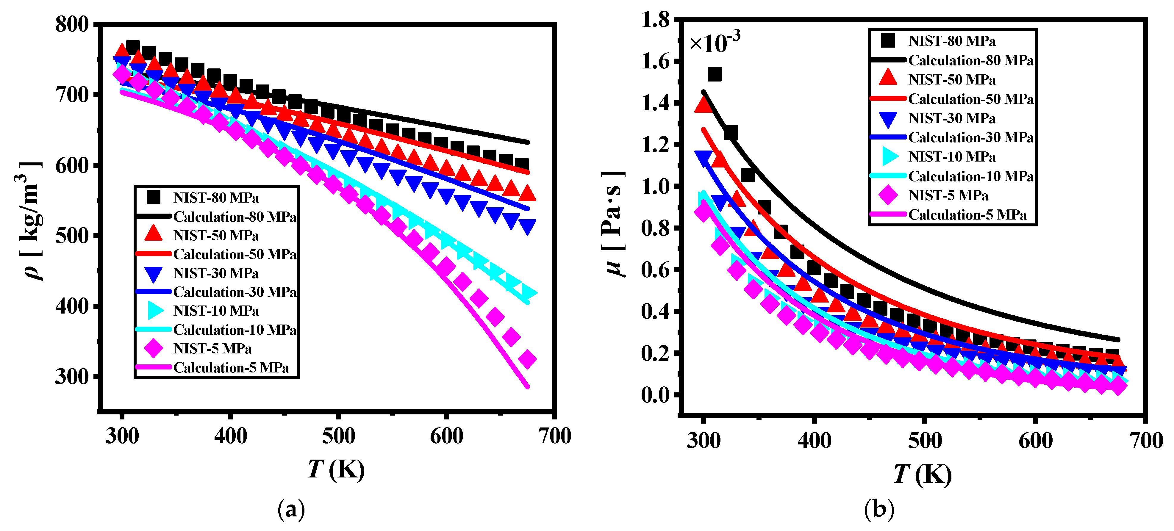
2.3. Calculation Method of Physical Properties
2.4. Turbulence Model Validation
2.5. Data Reduction
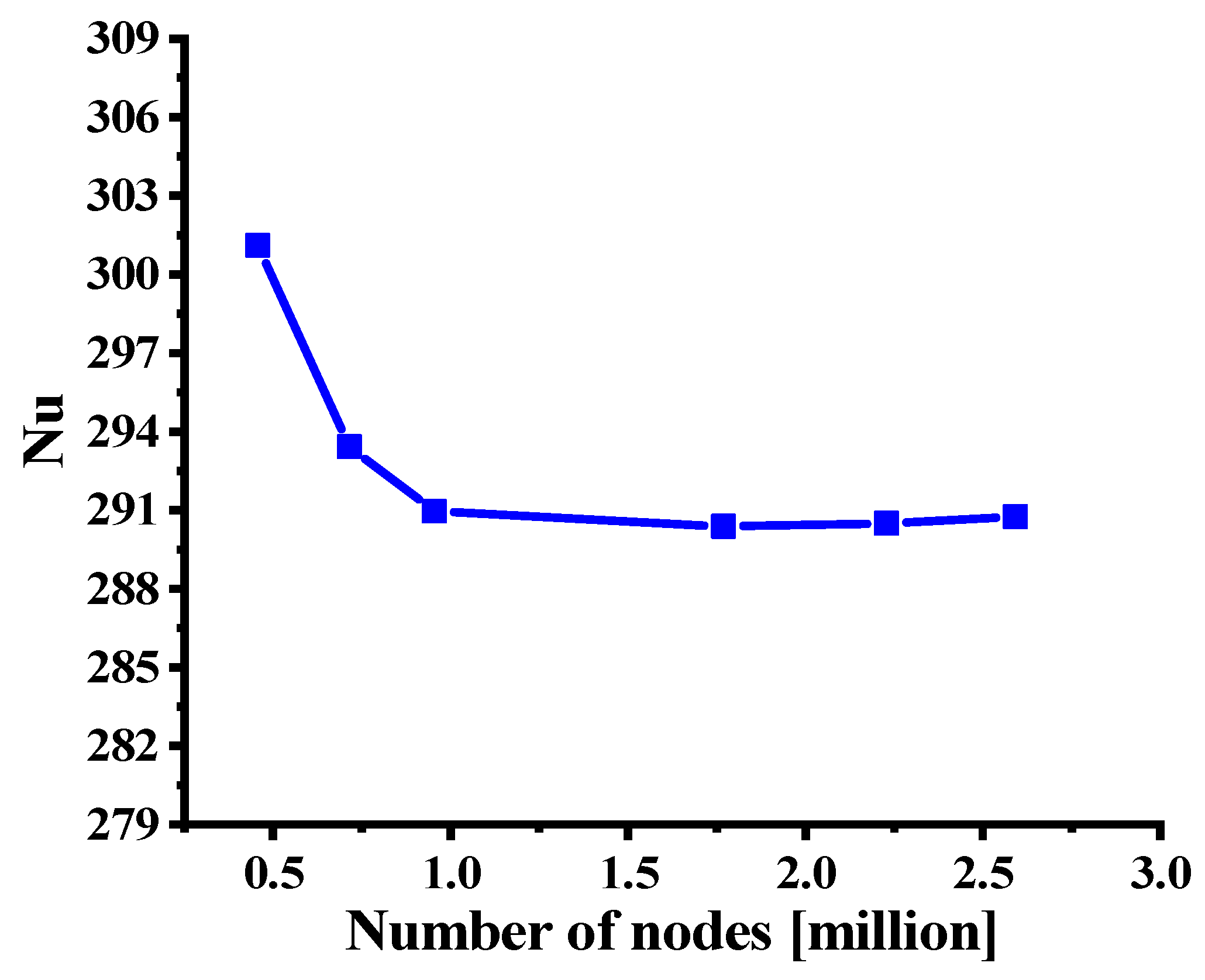
2.6. Grid Independence Validation
3. Results and Discussions
3.1. Influence of Rotational Speed on Physical Properties
3.2. Flow Characteristic Analysis
3.3. Analysis of Heat Transfer Characteristics
4. Conclusions
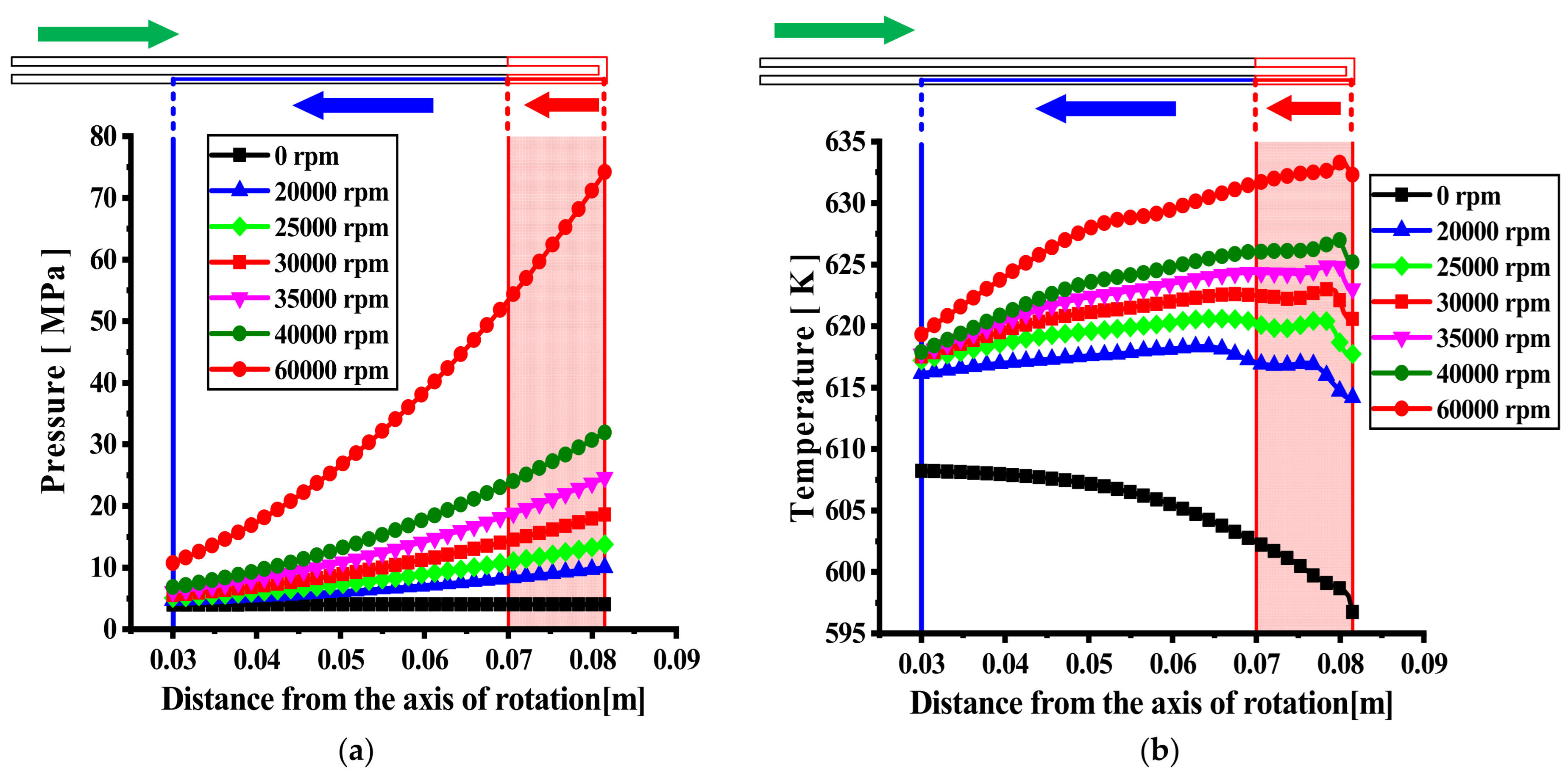
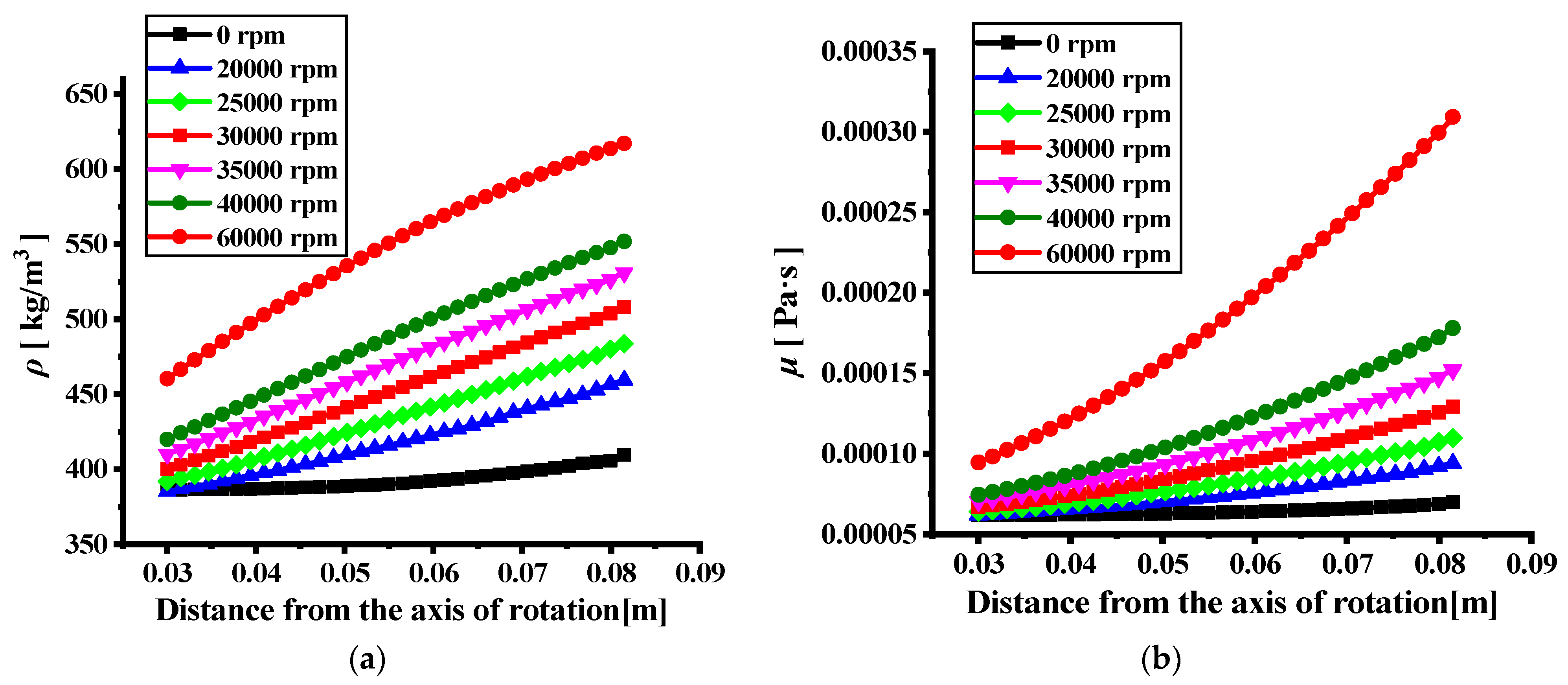
- (1)
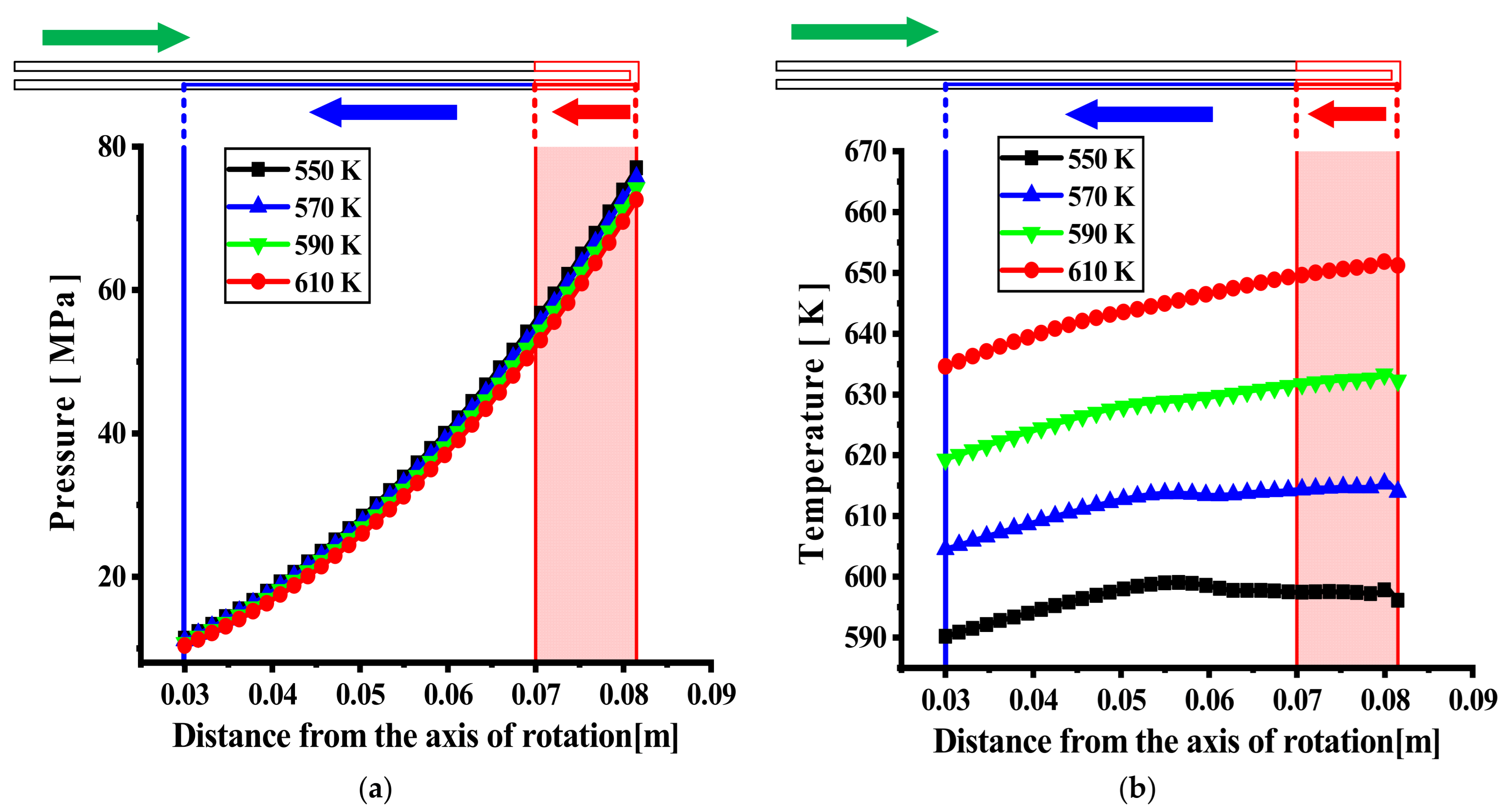
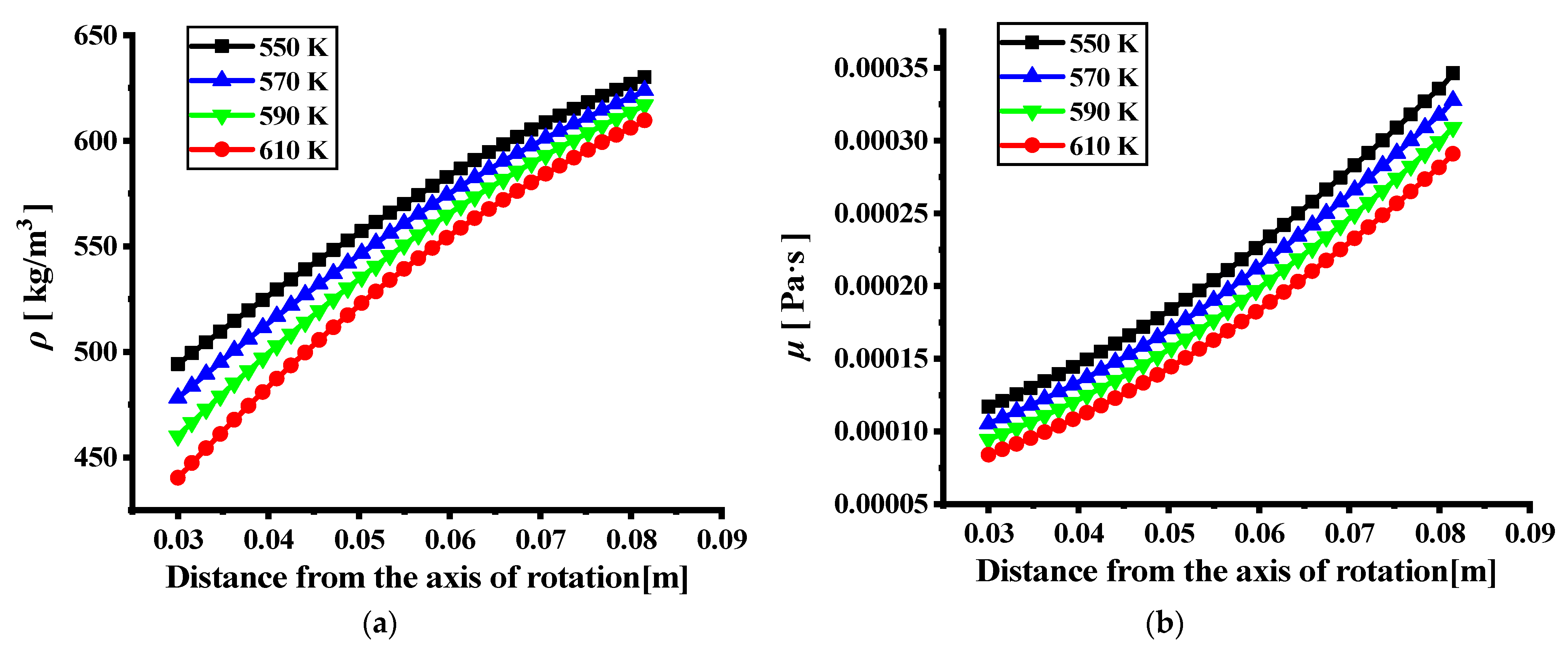
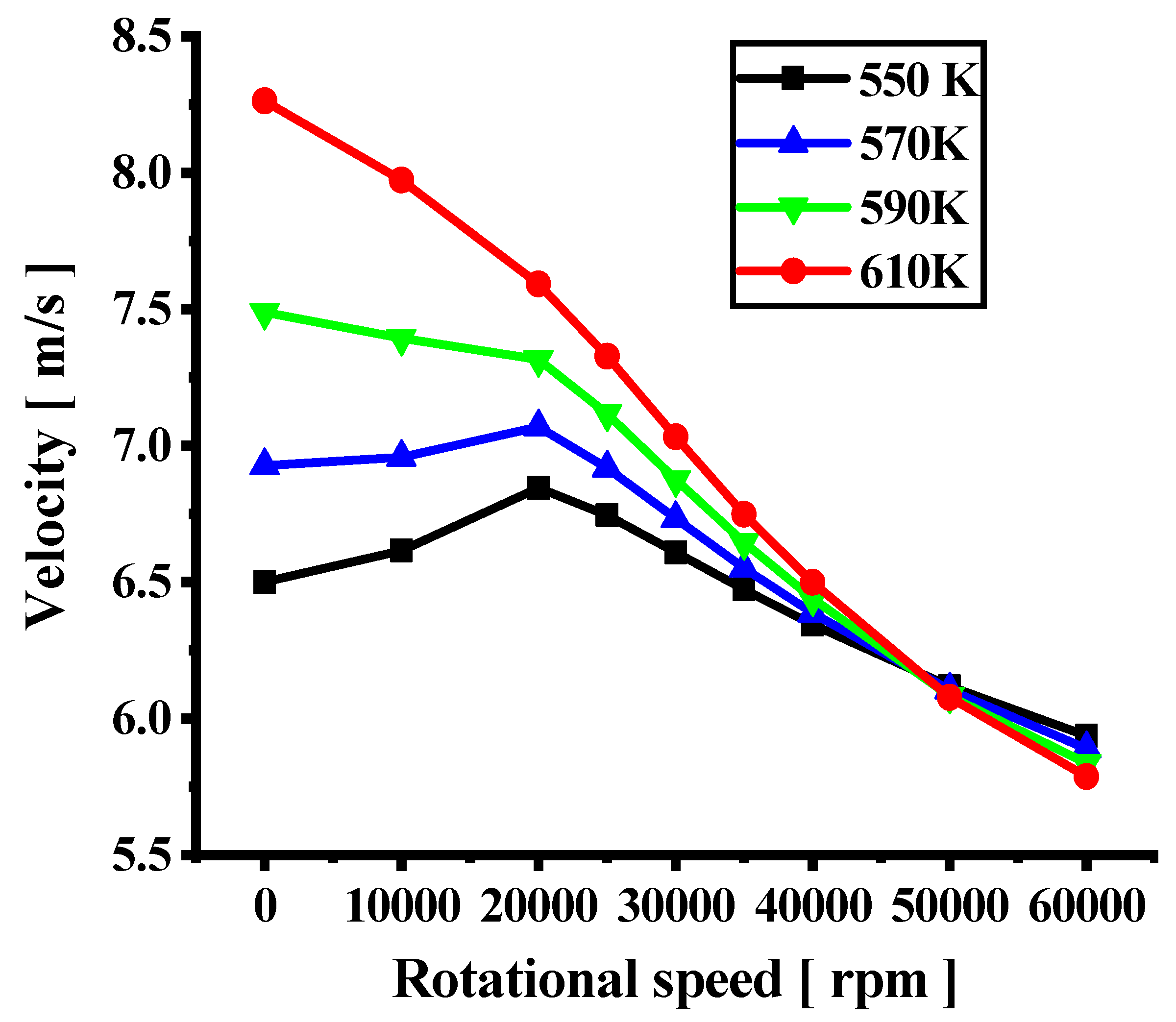
- The pressure and temperature of the fuel in the channel increase significantly with an increase in the rotational speed under the same inlet temperature conditions. The dynamic viscosity and density of hydrocarbon fuels increase significantly with an increase in the pressure. Compared to the static condition, the density and dynamic viscosity of the hydrocarbon fuel increase by a maximum of 65.1% and 405%, respectively, under the rotating condition. This can cause an obvious reduction in the fuel velocity, which will affect the level of heat exchange.
- (2)
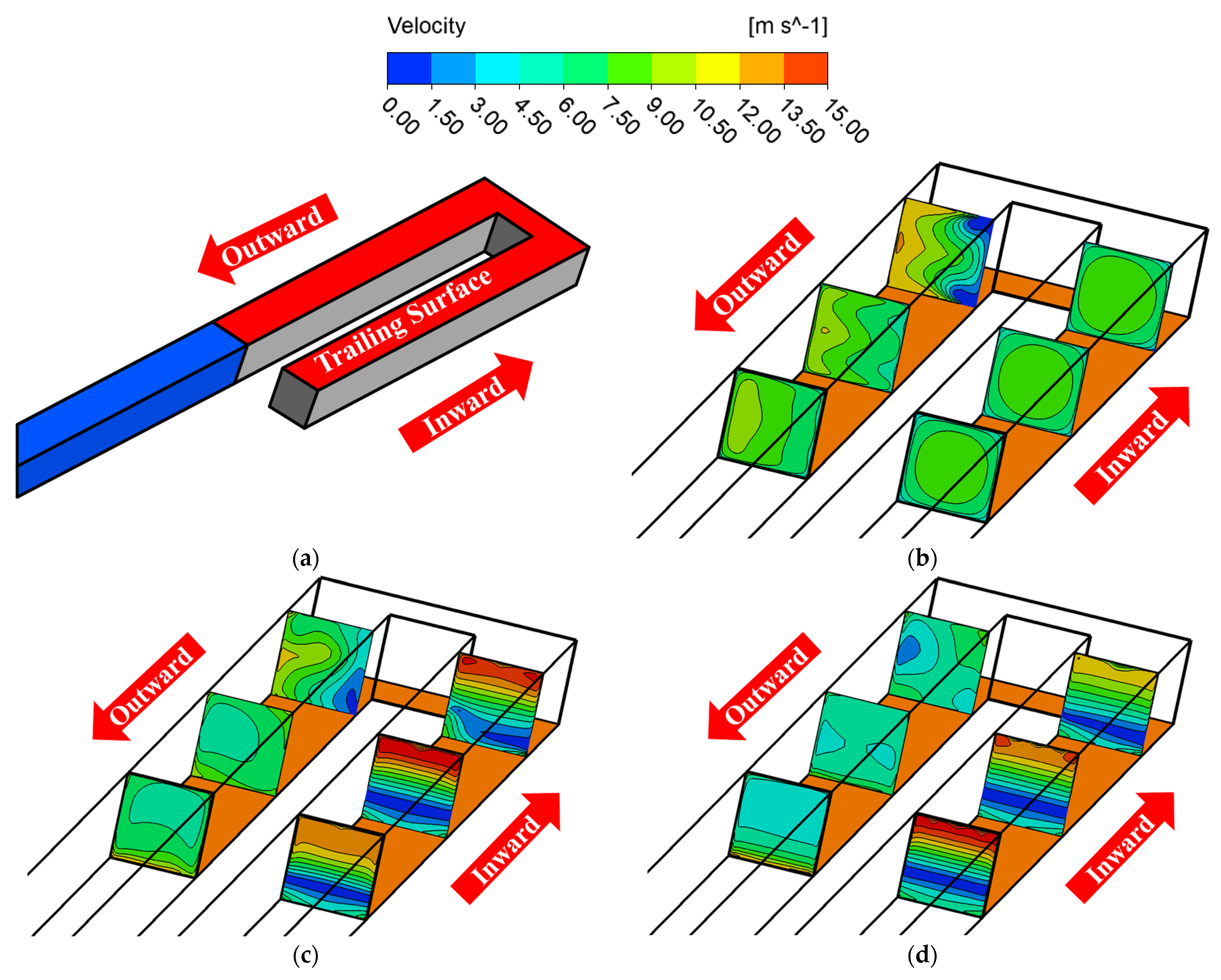
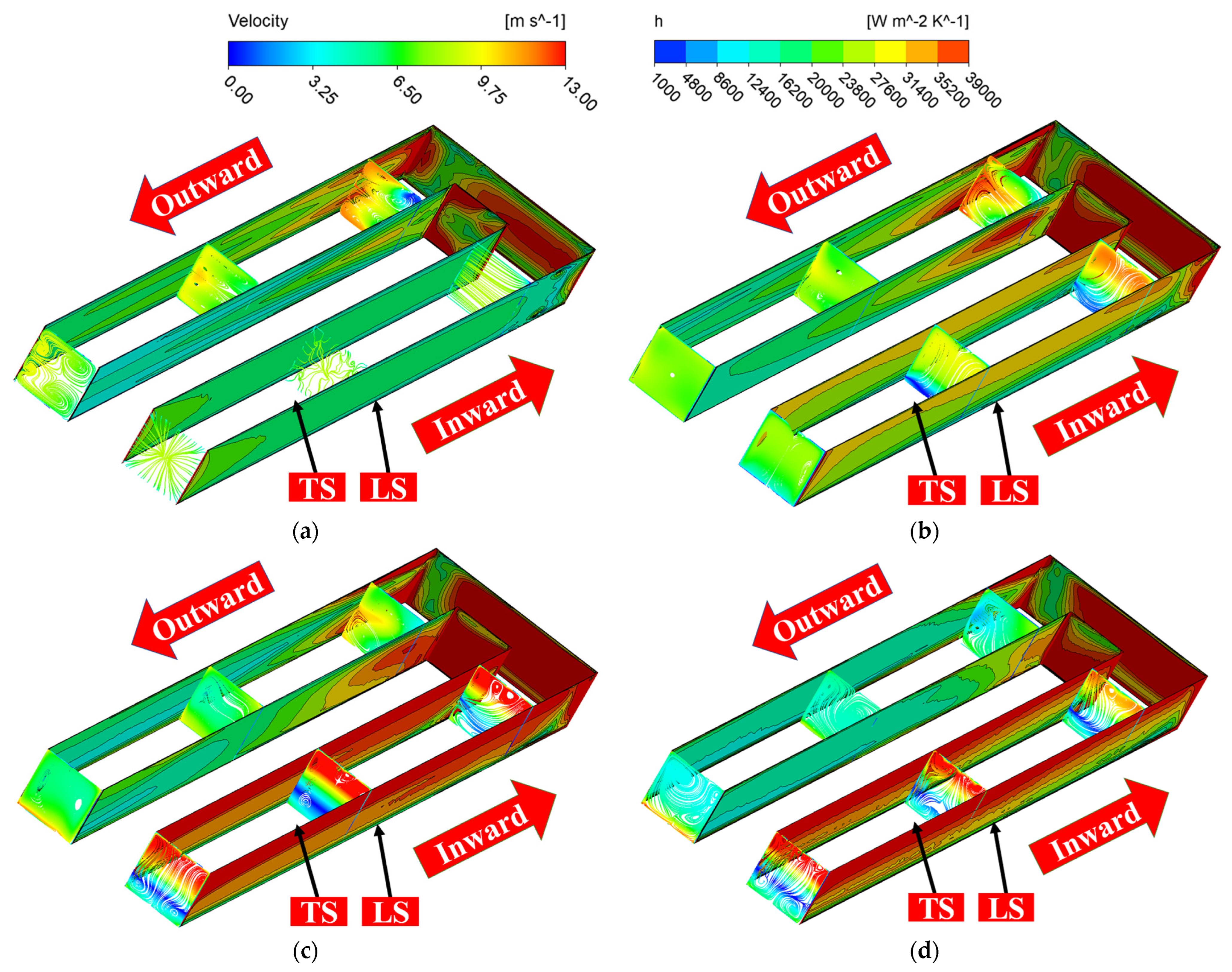
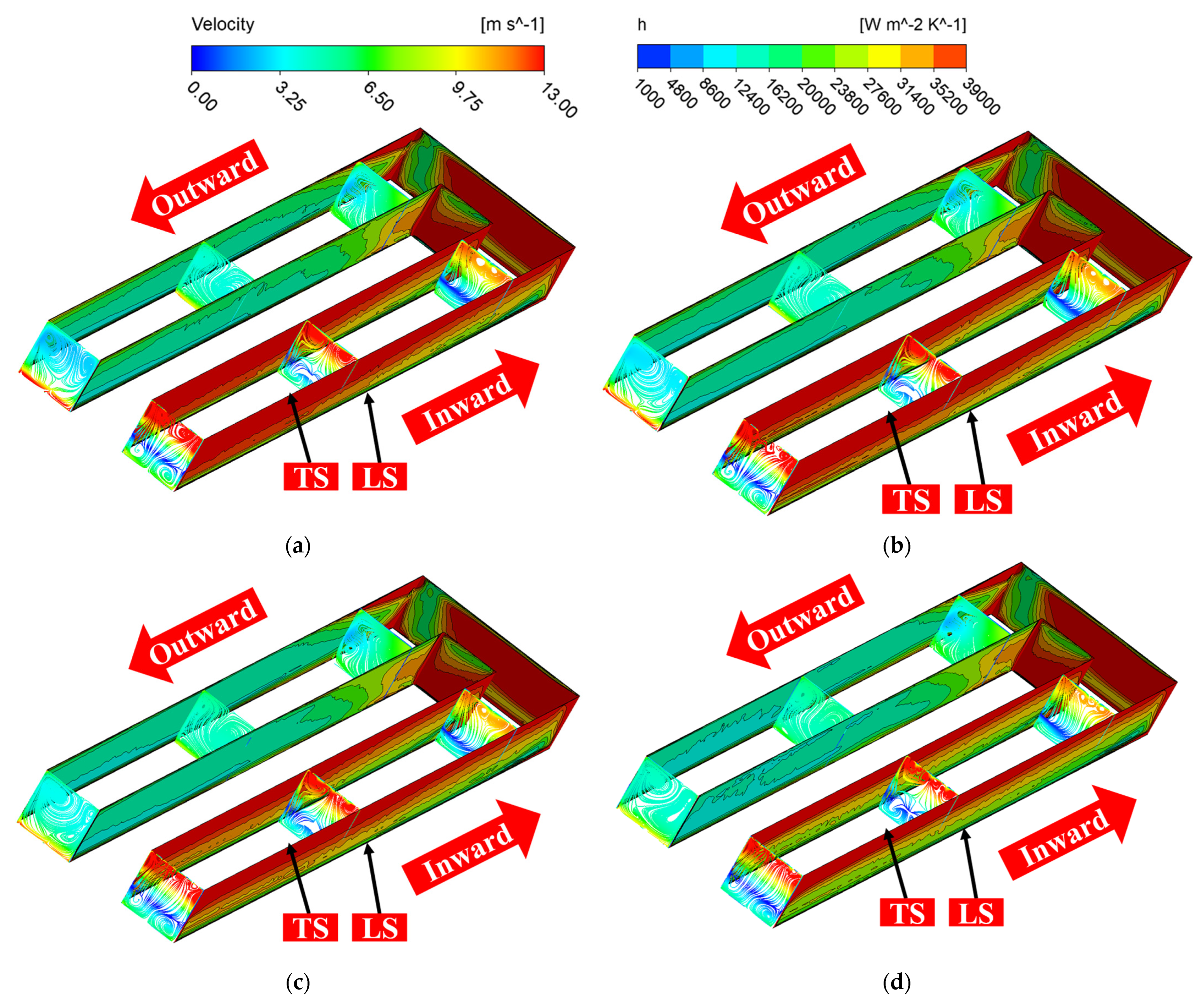
- The effect of the Coriolis force is greater in the first flow channel than that in the second flow channel under rotational conditions. There is an obvious delamination of the velocity in the first flow passage. However, the flow velocity in the second flow passage does not show obvious delamination. The backflow phenomenon near the leading surface corresponding to the first flow passage is enhanced with an increase in the rotational speed.
- (3)
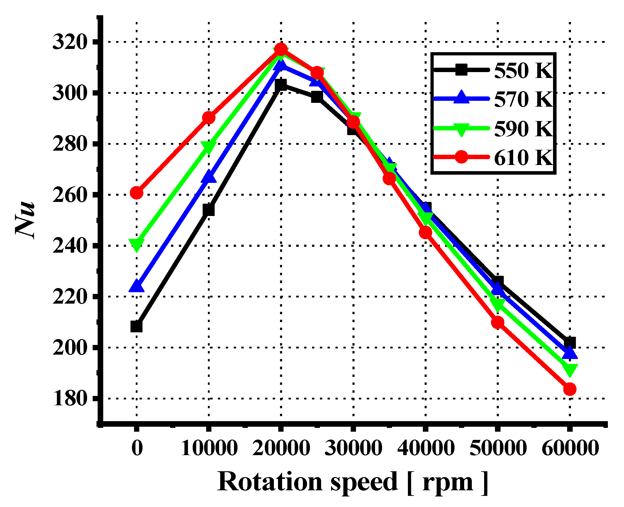
- The combined effect of the physical properties of the fuel and the Coriolis force results in the convective heat transfer coefficient, and the Nusselt number of the channel first increases and then decreases with an increase in the rotational speed. Compared to the static condition, the convective heat transfer coefficient and Nusselt number increase by a maximum of 69.7% and 45.6%, respectively, under the rotating condition. There is a critical rotational speed of the channel, which corresponds to the Nusselt number maximum. The critical rotational speed is 20,000 rpm at different inlet temperature conditions.
Author Contributions
Funding
Data Availability Statement
Acknowledgments
Conflicts of Interest
Nomenclature
| D | hydraulic diameter (mm) |
| T | temperature (K) |
| h | convective heat transfer coefficient (W/m2/K) |
| ∆T | logarithmic mean temperature difference (K) |
| q | heat flux (W/m2) |
| Nu | Nusselt number |
| Greek symbols | |
| ρ | density (kg/m3) |
| μ | dynamic viscosity (Pa·s) |
| λ | thermal conductivity (W/m/K) |
| Subscripts | |
| heat-in | inlet of heating section |
| heat-out | outlet of heating section |
| b | bulk value |
| w | wall |
| Abbreviations | |
| LS | leading surface |
| TS | trailing surface |
References
- Zhang, D.; Qin, J.; Feng, Y.; Ren, F.; Bao, W. Performance evaluation of power generation system with fuel vapor turbine onboard hydrocarbon fueled scramjets. Energy 2014, 77, 732–741. [Google Scholar] [CrossRef]
- Power, Energy, Thermal, Integration, and Controls Research Program; Solicitation Number: FA8650-19-S-2001; Department of the Air Force, Air Force Materiel Command, AFRL/RQK–WPAFB: Washington, DC, USA, 2001.
- Macheret, S.O.; Shneider, M.N.; Miles, R.B. Magnetohydrodynamic Power Extraction from Cold Hypersonic Airflows with External Ionizers. J. Propuls. Power 2002, 18, 424–431. [Google Scholar] [CrossRef]
- Vatazhin, A.B.; Gus’kov, O.V.; Danilov, M.K.; Kopchenov, V.I. Magnetogasdynamic generation of electrical energy in models of aircraft with a high-speed jet engine. Fluid Dyn. 2009, 44, 612–620. [Google Scholar] [CrossRef]
- Huang, H.L.; Li, L.Y.; Zhu, G.P.; Li, L. Performance investigation of plasma magnetohydrodynamic power generator. Appl. Math. Mech. 2018, 39, 423–436. [Google Scholar] [CrossRef]
- Elfert, M.; Voges, M.; Klinner, J. Detailed Flow Investigation Using PIV in a Rotating Square-Sectioned Two-Pass Cooling System with Ribbed Walls; Report Nvo.: GT2008-51183; ASME: New York, NY, USA, 2008. [Google Scholar]
- Qiu, L.; Deng, H.; Sun, J.; Tao, Z.; Tian, S. Pressure drop and heat transfer in rotating smooth square U-duct under high rotation numbers. Int. J. Heat Mass Transf. 2013, 66, 543–552. [Google Scholar] [CrossRef]
- Deng, H.; Qiu, L.; Tao, Z.; Tian, S. Heat transfer study in rotating smooth square U-duct at high rotation numbers. Int. J. Heat Mass Transf. 2013, 66, 733–744. [Google Scholar] [CrossRef]
- Schüler, M.; Dreher, H.M.; Neumann, S.O.; Weigand, B.; Elfert, M. Numerical predictions of the effect of rotation on fluid flow and heat transfer in an engine-similar two-pass internal cooling channel with smooth and ribbed walls. J. Turbomach. 2012, 134, 021021. [Google Scholar] [CrossRef]
- Al-Hadhrami, L.; Han, J.-C. Effect of rotation on heat transfer in two-pass square channels with five different orientations of 45° angled rib turbulators. Int. J. Heat Mass Transf. 2003, 46, 653–669. [Google Scholar] [CrossRef]
- Han, J.-C. Fundamental gas turbine heat transfer. J. Therm. Sci. Eng. Appl. 2013, 5, 021007. [Google Scholar] [CrossRef]
- Dutta, S.; Han, J.-C.; Lee, C.P. Local heat transfer in a rotating two-pass ribbed triangular duct with two model orientations. Int. J. Heat Mass Transf. 1996, 39, 707–715. [Google Scholar] [CrossRef]
- Han, J.; Zhang, Y. High performance heat transfer ducts with parallel broken and V-shaped broken ribs. Int. J. Heat Mass Transf. 1992, 35, 513–523. [Google Scholar] [CrossRef]
- Ekkad, S.V.; Huang, Y.; Han, J.-C. Detailed heat transfer distributions in two-pass square channels with rib turbulators and bleed holes. Int. J. Heat Mass Transf. 1998, 41, 3781–3791. [Google Scholar] [CrossRef]
- Ekkad, S.V.; Han, J.-C. Detailed heat transfer distributions in two-pass square channels with rib turbulators. Int. J. Heat Mass Transf. 1997, 40, 2525–2537. [Google Scholar] [CrossRef]
- Park, J.; Han, J.; Huang, Y.; Ou, S.; Boyle, R. Heat transfer performance comparisons of five different rectangular channels with parallel angled ribs. Int. J. Heat Mass Transf. 1992, 35, 2891–2903. [Google Scholar] [CrossRef]
- Han, J.; Park, J. Developing heat transfer in rectangular channels with rib turbulators. Int. J. Heat Mass Transf. 1988, 31, 183–195. [Google Scholar] [CrossRef]
- Han, J.-C.; Zhang, Y.-M.; Kalkuehler, K. Uneven wall temperature effect on local heat transfer in a rotating two-pass square channel with smooth walls. J. Heat Transf. 1993, 115, 912–920. [Google Scholar] [CrossRef]
- Parsons, J.A.; Han, J.-C.; Zhang, Y. Effect of model orientation and wall heating condition on local heat transfer in a rotating two-pass square channel with rib turbulators. Int. J. Heat Mass Transf. 1995, 38, 1151–1159. [Google Scholar] [CrossRef]
- Han, J.C.; Zhang, Y.M.; Lee, C.P. Augmented heat transfer in square channels with parallel, crossed, and V-shaped angled ribs. J Heat Transf. 1991, 113, 590–596. [Google Scholar] [CrossRef]
- Han, J.C.; Chen, H.C. Turbine blade internal cooling passages with rib turbulators. J. Propuls. Power 2006, 22, 226–248. [Google Scholar] [CrossRef]
- Fu, Y.; Wen, J.; Tao, Z.; Xu, G.; Huang, H. Experimental research on convective heat transfer of supercritical hydrocarbon fuel flowing through U-turn tubes. Appl. Therm. Eng. 2017, 116, 43–55. [Google Scholar] [CrossRef]
- Sun, X.; Meng, H. Large eddy simulations and analyses of hydrocarbon fuel heat transfer in vertical upward flows at supercritical pressures. Int. J. Heat Mass Transf. 2021, 170, 120988. [Google Scholar] [CrossRef]
- Sun, X.; Meng, H.; Zheng, Y. Asymmetric heating and buoyancy effects on heat transfer of hydrocarbon fuel in a horizontal square channel at supercritical pressures. Aerosp. Sci. Technol. 2019, 93, 105358. [Google Scholar] [CrossRef]
- XSun, X.; Xu, K.; Meng, H.; Zheng, Y. Buoyancy effects on supercritical-pressure conjugate heat transfer of aviation kerosene in horizontal tubes. J. Supercrit. Fluids 2018, 139, 105–113. [Google Scholar]
- Sun, F.; Li, Y.; Manca, O.; Xie, G. An evaluation on the laminar effect of buoyancy-driven supercritical hydrocarbon fuel flow and heat transfer characteristics. Int. J. Heat Mass Transf. 2019, 142, 118414. [Google Scholar] [CrossRef]
- Zhu, J.; Tao, K.; Tao, Z.; Qiu, L. Heat transfer degradation of buoyancy involved convective RP-3 hydrocarbon fuel in vertical tubes with various diameters under supercritical pressure. Appl. Therm. Eng. 2019, 163, 114392. [Google Scholar] [CrossRef]
- Wen, J.; Huang, H.; Jia, Z.; Fu, Y.; Xu, G. Buoyancy effects on heat transfer to supercritical pressure hydrocarbon fuel in a horizontal miniature tube. Int. J. Heat Mass Transf. 2017, 115, 1173–1181. [Google Scholar] [CrossRef]
- Liu, B.; Zhu, Y.; Yan, J.-J.; Lei, Y.; Zhang, B.; Jiang, P.-X. Experimental investigation of convection heat transfer of n-decane at supercritical pressures in small vertical tubes. Int. J. Heat Mass Transf. 2015, 91, 734–746. [Google Scholar] [CrossRef]
- Yan, J.; Liu, S.; Guo, P.; Bai, C. Experimental investigation on convection heat transfer of supercritical hydrocarbon fuel in a long mini tube. Exp. Therm. Fluid Sci. 2020, 115, 110100. [Google Scholar] [CrossRef]
- Zhang, C.; Xu, G.; Gao, L.; Tao, Z.; Deng, H.; Zhu, K. Experimental investigation on heat transfer of a specific fuel (RP-3) flows through downward tubes at supercritical pressure. J. Supercrit. Fluids 2012, 72, 90–99. [Google Scholar] [CrossRef]
- Pu, H.; Li, S.; Dong, M.; Jiao, S.; Wang, Y.; Shang, Y. Convective heat transfer and flow resistance characteristics of supercritical pressure hydrocarbon fuel in a horizontal rectangular mini-channel. Exp. Therm. Fluid Sci. 2019, 108, 39–53. [Google Scholar] [CrossRef]
- Feng, S.; Cheng, X.; Bi, Q.; Pan, H.; Liu, Z. Experimental investigation on convective heat transfer of hydrocarbon fuel in circular tubes with twisted-tape inserts. Int. J. Heat Mass Transf. 2019, 146, 118817. [Google Scholar] [CrossRef]
- Guo, Y.; Yang, Z.; Jiang, L.; Liu, Z.; Bi, Q. Convective heat transfer characteristics of supercritical hydrocarbon fuel in small non-circular cross-section channels, AIAA-2014-2967. In Proceedings of the 11th AIAA/ASME Joint Thermophysics and Heat Transfer Conference, Atlanta, GA, USA, 16–20 June 2014. [Google Scholar]
- Jiang, Y.; Xu, Y.; Qin, J.; Zhang, S.; Chetehouna, K.; Gascoin, N.; Bao, W. The flow rate distribution of hydrocarbon fuel in parallel channels with different cross section shapes. Appl. Therm. Eng. 2018, 137, 173–183. [Google Scholar] [CrossRef]
- Li, F.; Li, Z.; Jing, K.; Wang, L.; Zhang, X.; Liu, G. Thermal cracking of endothermic hydrocarbon fuel in regenerative cooling channels with different geometric structures. Energy Fuels 2018, 32, 6524–6534. [Google Scholar] [CrossRef]
- Zhang, S.; Qin, J.; Xie, K.; Feng, Y.; Bao, W. Thermal behavior inside scramjet cooling channels at different channel aspect ratios. J. Propuls. Power 2016, 32, 57–70. [Google Scholar] [CrossRef]
- Jiang, P.; Lu, Z.; Guo, Y.; Zhu, Y. Experimental investigation of convective heat transfer of hydrocarbon fuels at supercritical pressures within rotating centrifugal channel. Appl. Therm. Eng. 2018, 147, 101–112. [Google Scholar] [CrossRef]
- Sun, H.; Qin, J.; Li, H.; Huang, H.; Yan, P. Research of a combined power and cooling system based on fuel rotating cooling air turbine and organic Rankine cycle on hypersonic aircraft. Energy 2019, 189, 116183. [Google Scholar] [CrossRef]
- Kim, S.-K.; Choi, H.-S.; Kim, Y. Thermodynamic modeling based on a generalized cubic equation of state for kerosene/LOx rocket combustion. Combust. Flame 2012, 159, 1351–1365. [Google Scholar] [CrossRef]
- Poling, B.E.; Prausnitz, J.M.; O’connell, J.P. The Properties of Gases and Liquids, 5th ed.; McGraw-Hill Professional: New York, NY, USA, 2001. [Google Scholar]
- Dong, M.; Feng, Y.; Wu, K.; Qin, J.; Huang, H. Heat transfer characteristics of supercritical pressure hydrocarbon fuels in rotating trapezoidal channels. Int. Commun. Heat Mass Transf. 2023, 140, 106556. [Google Scholar] [CrossRef]
- Lemmon, E.W.; Huber, M.L.; McLinden, M.O. NIST Standard Reference Database23: Reference Fluid Thermodynamic and Transport Properties-REFPROP, Version 9.1; National Institute of Standards and Technology: Gaithersburg, MD, USA, 2013.
- Li, X.; Zhang, S.; Qin, J.; Bao, W. Parametric analysis on the thermal behavior of cracking hydrocarbon fuel flow inside asymmetry heated cooling channels with micro-ribs. Int. J. Heat Mass Transf. 2020, 160, 120154. [Google Scholar] [CrossRef]
- Li, X.; Qin, J.; Zhang, S.L.; Cui, N.G.; Bao, W. Effects of microribs on the thermalbehavior of transcritical n-decane in asymmetric heated rectangular mini-channels under near critical pressure. J. Heat Transfer. 2018, 140, 122402. [Google Scholar] [CrossRef]
- Li, Y.; Xie, G.N.; Sunden, B. Flow and thermal performance of supercritical n-decane in double-layer channels for regenerative cooling of a scramjet combustor. Appl. Therm. Eng. 2020, 180, 115695. [Google Scholar] [CrossRef]
- ANSYS, Inc. ANSYS 13 FLUENT User’s Guide; ANSYS: Canonsburg, PA, USA, 2010. [Google Scholar]
- Lu, Z.L.; Zhu, Y.H.; Guo, Y.X.; Jiang, P.X. Experimental Investigation of Convective Heat Transfer of Supercritical Pressure Hydrocarbon Fuel in a Horizontal Section of a Rotating U-Duct. J. Heat Transfer. 2019, 141, 101702. [Google Scholar] [CrossRef]
- Li, H.; Qin, J.; Jiang, Y.; Zhang, D.; Cheng, K.; Bao, W. Experimental and theoretical investigation of power generation scheme driven by thermal cracked gaseous hydrocarbon fuel for hypersonic vehicle. Energy Convers. Manag. 2018, 165, 334–343. [Google Scholar] [CrossRef]


Disclaimer/Publisher’s Note: The statements, opinions and data contained in all publications are solely those of the individual author(s) and contributor(s) and not of MDPI and/or the editor(s). MDPI and/or the editor(s) disclaim responsibility for any injury to people or property resulting from any ideas, methods, instructions or products referred to in the content. |
© 2023 by the authors. Licensee MDPI, Basel, Switzerland. This article is an open access article distributed under the terms and conditions of the Creative Commons Attribution (CC BY) license (https://creativecommons.org/licenses/by/4.0/).
Share and Cite
Dong, M.; Huang, H. Hydrocarbon Fuel Flow and Heat Transfer Investigation in Rotating Channels. Energies 2023, 16, 5020. https://doi.org/10.3390/en16135020
Dong M, Huang H. Hydrocarbon Fuel Flow and Heat Transfer Investigation in Rotating Channels. Energies. 2023; 16(13):5020. https://doi.org/10.3390/en16135020
Chicago/Turabian StyleDong, Mengqiang, and Hongyan Huang. 2023. "Hydrocarbon Fuel Flow and Heat Transfer Investigation in Rotating Channels" Energies 16, no. 13: 5020. https://doi.org/10.3390/en16135020
APA StyleDong, M., & Huang, H. (2023). Hydrocarbon Fuel Flow and Heat Transfer Investigation in Rotating Channels. Energies, 16(13), 5020. https://doi.org/10.3390/en16135020