Abstract
The laser extinction method (LEM) is particularly suitable for measuring particle sizes in flames because this method, which is based on the Beer–Lambert law, is non-intrusive and easy to implement. In the LEM, the interpretation of the extinction data is usually developed under the assumption that light extinction due to scattering is a result of the superposition of single scattering by individual particles; however, this could be violated for flames with dense concentrations of particles in which multiple scattering could occur. Quantifying the effect of multiple scattering under general conditions is still a formidable problem. In this work, we carried out a series of careful measurements of the laser extinction using standard particles of various known sizes, number densities and optical path lengths, all under the condition that the acceptance angle of the detector was limited to nearly zero. Combined with a four-flux model, we quantitatively analyzed the effect of multiple scattering on the size measurement using the LEM. The results show that the effect of multiple scattering could be ignored when the optical thickness is less than two under strict restrictions on the detector acceptance angle. Guided by this, the size distribution of an alumina () particle sample was measured by the LEM with dual wavelengths. Parameterized distributions were solved with the help of graph plotting, and the results compared well with the measurement from the Malvern particle size analyzer. The same method was then used to measure the particle size distribution in the plume of a solid rocket motor (SRM). The use of an off-axis parabolic mirror in the experimental setup could suppress the jitter of light passing through the SRM plume, and the particle size in the plume of the measured SRM was in the order of microns.
1. Introduction
In industrial processes, many combustion processes include particle combustion, and the factors affecting the combustion efficiency are not only related to the characteristics of the fuel itself but also to the flow state and size of the particles. For example, the combustion of fuel in an internal combustion engine is the combustion of fuel particles after atomization, and the size of the fuel particles after atomization affects the combustion efficiency and exhaust emissions [1,2,3]. For instance, coal combustion in a boiler is the combustion process of pulverized coal in the form of granules, and the morphology and kinematic state of the particles change dramatically during the combustion process, while the morphology, size and kinematic parameters of the fuel particles have a significant impact on the performance of the burner [4,5]. The kinematic state and size of the fuel particles are a prerequisite for the efficient organization of the mass flow and are important conditions for the optimization of the burner.
In the aerospace field, rockets and certain spacecraft mostly use composite-modified double base (CMDB) propellants with specific properties or double base (DB) propellants as fuel, and metal particles such as lithium, magnesium and aluminum are generally added to the propellant to improve the specific impulse of the propellant; non-metallic particles of boron can also be added [6,7]. In addition to increasing the specific impulse of a propellant, the particles contain propellant that can also suppress the oscillatory combustion of the propellant [8,9]; though this principle is complex and has not been fully understood, there is a consensus that the effect of metal particles suppressing the oscillatory combustion of the propellant can be related to the size of the metal particles after combustion. Therefore, the size of the metal particles after combustion is a parameter that needs to be considered when designing solid rocket motors (SRMs). However, the addition of metal particles to propellants can lead to some negative effects, which include two-phase flow losses in the SRMs [10,11,12] and nozzle erosion caused by added particles [13,14,15]. Some solid rocket motors work in outer space, where the large particles or debris produced by these SRMs are a kind of space debris, and these particles pose hazards to space transportation [16]. Large solid particles pose a threat to equipment that operates in space, where particles larger than 100 m in diameter can penetrate astronauts’ space suits and particles larger than 5 mm in diameter can penetrate the weak parts of the space station [17]. To date, there are relatively few internal and external flow field parameters that can be measured for SRMs. The curve of the motor thrust and front-end pressure in SRM over time can only almost be measured [18,19]. Only a few sets of experimental data in the published literature can be used to verify the theoretical analysis and numerical calculation of the two-phase flow in solid rocket motors, and the measurement of particle velocity and particle size in SRMs’ plume flames can provide empirical support for the theory of a new energy loss model [20]. For these reasons, there has been wide demand for the online measurement of particle size in the plume flames of SRMs.
To measure the size of the particles in flames, optical measurement technologies should be prioritized due to their non-intrusive and non-contact advantages [21,22]; however, combusting environments bring measurements great challenges [22] that include where the number density of the measured particles is uncontrollable and usually very high; on the other hand, light passing through the flame can be deflected in an uncertain direction due to the variation in the gas density when raised from the temperature gradient of the field, especially for large-scale measurement objects. An example of a high particle number density leading to failure in the particle size measurement is the failure of PDPA in dense diesel fuel [23]. As a result of the above challenges, many studies on particle size in flames use sampling methods [16,22,24]. However, among the existing online particle size measurement technologies, the light extinction method (LEM) may be the most suitable approach for measuring the particle size of dense particles in combusting environments. The advantages of this technique over other existing online particle size measurement techniques such as angular scattering method, diffraction method, PDPA, etc., include: (1) The technique can be used for dense particle size measurement. (2) By means of a special experimental setup design, the technique can suppress the jitter of the laser passing through the flame. (3) The technique is simple to set up and easy to measure, requiring only the data of the laser transmittance [25]. (4) Compared to particle size measurement techniques that require the scattered signal of the particles to be measured, usually the intensity of the transmitted laser is higher than that of the scattered laser, making it easier to measure and eliminating the need for an expensive detector at the receiving end. The measurement principle of the LEM is the Beer–Lambert law [26], which is based on the hypothesis that the scattered light between the measured particles satisfies the single scattering condition; that is, the detector does not receive any scattered light from particles in the measurement volume. In other words, the multiple scattering effect is completely ignored. In earlier examples in the literature, researchers used the LEM to measure the particle size without discussing the multiple scattering effects [27,28]. The fact that many parameters can affect the multiple scattering effect complicates this problem, and the random distribution of particle positions can lead to difficulties in determining not only the intensity of the scattered light but also the phase of the electromagnetic field. These factors make it almost impossible to theoretically determine the light intensity distribution in the case of multiple scattering. There is also no universal conclusion as to when multiple scattering occurs and when the effects of multiple scattering can be ignored for the LEM.
In 1969, Kerker [29] showed that the effect of multiple scattering could be ignored when the transmission of photons through a sample of particles was greater than 90%. In 1981, Bayvel and Jones [30] showed that the effect of backscattering could be ignored if the transmittance was greater than 60%. In 2007, the scattering of eight particles with a wavelength size and randomly assigned positions was calculated by Mishchenko et al. [31] using the T-matrix method, and the results showed that the single-scattering approximation (SSA) was satisfied only when the distance between particles was large and the number density of particles was low. When the volume fraction of particles was less than 1% and , where x represents the wave number of the particle size in the surrounding medium and is the average distance between two particles, the effects of multiple scattering were negligible. Su Mingxu et al. [32] used the Monte Carlo method to simulate different light wavelengths, particle sizes and different detection sizes and detector distances and compared the calculation results with those calculated using the Beer–Lambert law. The results showed that the influence of the multiple scattering effects on the particle size measurement using the LEM not only depended on the particle concentration but also on the size of the detector and the distance of the detector’s placement, which had a great influence on the measurement results. Reducing the particle concentration and the detector receiving area and increasing the detector distance could diminish the effect of multiple scattering on the measurement results. Swanson et al. [33] showed that by limiting the half-angle of acceptance in the detector, the effect of multiple scattering could be avoided up to an optical thickness of 10, where satisfied:
where represents the laser wavelength in the medium and is the particle diameter. However, this conclusion was based on only the limited transmittance data of standard polystyrene particles and did not take into account the sedimentation of polystyrene during the experiment.
Determining the conditions under which the particle multiple scattering effects can be ignored is a key point in the particle size experiment using an LEM. In this paper, this condition was investigated by measuring the transmittance of the polystyrene aqueous solution with the half-angle of acceptance in the detector, which satisfied Equation (1). To prevent the sedimentation of polystyrene particles from interfering with the measurement results, a magnetic stirrer was used to continuously stir the polystyrene solution. The particle size distribution of alumina was then measured using an LEM with two laser wavelengths and was compared with the result measured using the Malvern laser particle size analyzer. Finally, the size distribution of the particles in the SRM plume flame was measured. For this experiment, the problem to be solved was that the laser passing through the flame might not be received by the detector due to refraction caused by the density differences in the flame field.
2. Materials and Methods
The LEM’s measurement principle and two sets of experimental setups were used: one to determine the conditions for neglecting multiple scattering and another to measure the size distribution of alumina powder and particles in the SRM plume flame, which are described in this section.
2.1. Measurement Principle of the LEM (Beer–Lambert Law)
When a laser beam with light intensity irradiates a continuous homogeneous medium, the outgoing light intensity I is attenuated due to the absorption and scattering of the light by the medium. Assuming that the light intensity attenuation of the laser proceeding through a medium with a thickness of is , the relationship between the two is thought to be:
where represents turbidity. When Equation (2) is integrated along the direction of light propagation and boundary conditions are used, we obtain:
where is the optical thickness and l is the optical length. When the medium is a cloud of particles, and the multiple scattering effects between particles is ignored, can be expressed as:
where is the number density of the sample particles, is the particle diameter and is the extinction coefficient. For polydisperse particles, can also be easily derived.
is the function of particle size , laser wavelength and complex refractive index of m, which can be calculated according to the Mie theory [34]. Generally and are expressed as:
where
where is the refractive index of the particle, is the refractive index of the medium around the particle and k is a parameter that is related to the absorption coefficient of light.
2.2. Experimental Setup and Experimental Methods
Two experiments are presented here. The first experiment was designed to determine under what conditions the effects of multiple scattering could be ignored when measuring the particle size using the LEM, and the second was designed to measure the size distribution of the particles in flame.
2.2.1. Experimental Setup Used to Study the Multiple Scattering Effect
The transmittance of the laser passing through standard polystyrene particles and suspended in water with different optical thicknesses was measured. A schematic diagram of the experimental setup is shown in Figure 1a, and some photos of the experimental setup are shown in Figure 1b. The laser (generated by SUMLINEG-800), with a wavelength of 532 nm and a laser beam diameter of 1 mm, was split into two beams after passing through a beamsplitter, whose reflectance-to-transmittance ratio, T:R, was 1:9. The transmitted light was received by detector 1 (Thorlabs, PDA36A2), whose function was to monitor the actual output power of the laser in real time, and a bandpass filter with a center wavelength of 532 nm was placed in front of the detector. The reflected laser passed through an acrylic rectangular container filled with purified water, and a triangular sample box to which polystyrene particles were added was placed inside. The triangular box, the main dimensions of which are shown in Figure 1c, could be moved back and forth in the rectangular container so that the optical length l of the laser in the triangular box could be easily changed.
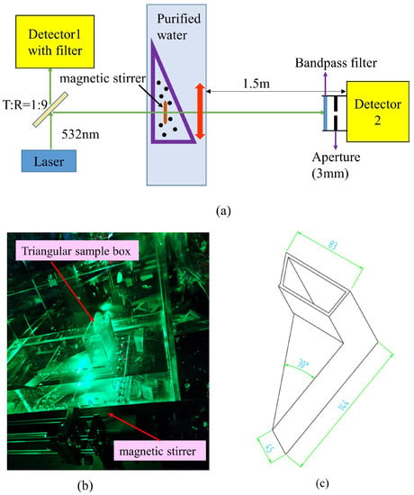
Figure 1.
Experimental setup for multiple scattering study. (a) Schematic diagram of the experimental setup. (b) Photographs of part of the experimental setup. (c) Dimensions of triangular sample box.
A magnetic stirrer was placed in the triangular box, and the sedimentation of polystyrene particles can be prevented by continuous stirring. The laser light, after passing through the polystyrene solution, was received by detector 2; in addition, a bandpass filter with a center wavelength of 532 nm and an aperture of 3 mm diameter was placed in front of detector 2. The diameter of the polystyrene that was used and the optical length l are listed in Table 1.

Table 1.
Experimental parameters.
The distance between detector 2 and the triangular box was about 1.5 m; therefore, Equation (1) could be satisfied. The light intensity ratio between the two detectors for every optical length l needed to be calibrated in advance before the particles were added in the triangular box, , as follows:
where and are the value of detector 1 and detector 2 when no particles are added in the triangular box, respectively; and , close to 10 mV, are the dark voltage of these two detectors; and the symbol ‘-’ denotes the averaging operation.
When polystyrene particles of a known mass were added to the triangular box, the triangular box was moved to the locations of different optical lengths l, and the voltages of the two detectors, and , were recorded for different optical lengths l; then, the laser transmittance of the particles was:
2.2.2. Experimental Setup Used to Measure the Size Distribution of Particles in Flame
The experimental setup for measuring the size distribution of the particles in the SRM plume flame using the LEM is shown in Figure 2. This experimental setup mainly included two parts: the transmitter and the receiver. Figure 2a is the schematic diagram of the experimental setup, and Figure 2b,c show the photos of the transmitter and receiver, respectively.
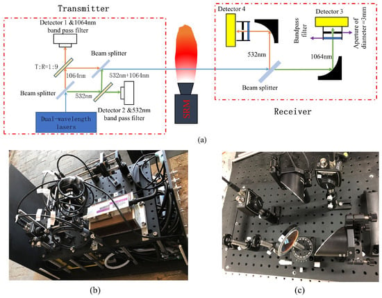
Figure 2.
Experimental setup for measuring the size distribution of particles in SRM plume flame. (a) Schematic diagram of the experimental setup. (b) Photographs of the transmitter. (c) Photographs of the receiver.
In the transmitter, the dual-wavelength laser-emitted laser beams had wavelengths of 532 nm and 1064 nm simultaneously. The two lasers’ wavelengths were separated after passing through the beam splitter, which reflected the 532 nm laser and transmitted the 1064 nm laser. The two separated lasers again passed through each beamsplitter, whose ratio of transmission to reflection, T:R, was approximately 1:9. The transmitted laser light was received by detectors 1 and 2, in front of which the corresponding bandpass filters were placed. Both the 532 nm and 1064 nm reflected lasers became collinear lasers again after passing through the beamsplitter.
As mentioned earlier, one of the problems that needed to be solved when measuring the size of the particles in the SRM plume flame was the jittering of the laser after passing through the flame due to the irregular laser deflection caused by the density difference of the flame. Without special treatment, the detectors in the receiver may not have been able to receive the transmitted light. To solve this problem, two off-axis parabolic mirrors were used in the receiver because the jittering laser reflected by an off-axis parabolic mirror always passed through the focal point of the mirror where the detectors were placed. The off-axis parabolic mirror had a cross-sectional diameter of 50.8 mm (2 inches) and a reflective focal length of 50.8 mm (2 inches). The main optical path at the receiver was as follows: the light from the dual-wavelength laser passing through the flame was split into two beams, a 532 nm one and a 1064 nm one, which were reflected by the off-axis parabolic mirror and received by detector 3 and detector 4, respectively. A bandpass filter and an aperture of a 3 mm diameter were placed in front of the detector. In this experiment, although bandpass filters were placed in front of each detector in the receiver to ensure that the detectors were as unaffected as possible by the flame’s own radiation, the laser was operated in pulse mode at 10 Hz for both wavelengths with a duty cycle of 50%. In the pulsed laser mode, if the detector value was when there was a laser output and when there was no laser output, the effect of the flame radiation on the measurement results could be eliminated by subtracting from .
In order to verify the accuracy of the particle size measurement taken using a dual-wavelength extinction method, the particle size of the alumina powder was measured using this experimental setup, and the measurement results were compared with the results measured by the Malvern laser particle size analyzer (MASTERSIZER 2000). The alumina powder needed to be dispersed when measured by the dual-wavelength extinction method; however, it could not be suspended in water because the density of alumina is about 4 times that of the water. Therefore, the alumina particles were cured in an epoxy resin. When the alumina particles were in the epoxy, the absorption effect of the epoxy on the laser had to be taken into account. To calculate the absorption of the laser light by the epoxy resin, an epoxy resin sample that did not contain particles was also made; the epoxy resin samples are shown in Figure 3. The sample in Figure 3a contained no aluminum oxide particles, whereas the sample in Figure 3b contained aluminum oxide particles. The two samples were identical in size, and the sample without alumina particles, shown in Figure 3a, was used to calibrate the absorption of the laser light by the epoxy resin; i.e., if a laser with an intensity of changed to after passing through the sample without alumina and to after passing through the sample containing alumina, the intensity ratio of the light caused by the alumina particles in the sample would be .
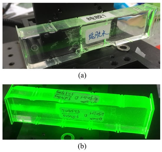
Figure 3.
Epoxy resin samples. (a) Epoxy resin sample without alumina. (b) Epoxy resin sample with alumina particles.
When measuring the particle size in the SRM plume flame, the measurement volume was 0.9 m from the nozzle outlet of the SRM. The receiver was placed approximately 2.2 m from the flame to ensure the measurement condition satisfied Equation (1).
3. Results and Discussion
In this section, the conditions under which the multiple scattering effects could be neglected is discussed, and the alumina particle sizes measured by the dual-wavelength extinction method and the Malvern laser particle size analyzer are compared. Finally, the results of the particle size distribution in the plume of a full SRM are presented.
3.1. Conditions for Neglecting the Multiple Scattering Effect
A four-flux model [35,36] was used here to study multiple scattering effects. In this model, the light in the sample could be classified into four fluxes:
- A collimated beam of intensity propagating to negative ;
- A diffuse radiation of intensity propagating to negative ;
- A collimated beam of intensity propagating to positive ;
- A diffuse radiation of intensity propagating to positive .
The negative is the direction of incidence in the laser, and the relationship between these four fluxes is as follows:
where
where is the particle number density, R is the radius of the particle, is the absorption coefficient, is the scattering coefficient calculated using Mie theory, is the average crossing parameter, and is the forward scattering coefficient, e.g.,
where is the scattered light intensity distribution function of , which is also calculated using Mie theory.
According to Equation (15) and Mie theory, the values of for the polystyrene particles with diameters of 1, 2 and 3 m in the water were 0.985, 0.942 and 0.955, respectively. In this paper, was taken as a constant value of two, just as in the paper [35]. Moreover, 0 because the k of polystyrene in Equation (6) is approximately equal to zero [37]. According to the four-flux model, the transmittance after the laser passed through the sample could be classified into two parts, collimate–collimate transmittance and collimate–diffuse transmittance due to the absence of diffuse–diffuse incident light. and were calculated as follows, depending on the boundary conditions:
In the four-flux model, the area of the detector in the receiver is assumed to be infinitely large; however, in practice, the area of the detector could not be infinitely large. Instead, to avoid the effects of multiple scattering, it needed to be as small as possible. was independent of the detector area but depended on it. For the experimental measurements, the transmittance needed to be:
where is the parameter that should depend on the geometry of the sample box; however, this would be difficult to analyze theoretically for a complicated structure. The value of was determined by fitting the polystyrene data with a diameter of 1 m using Equation (18), where was the only fitting parameter; thus, was . This value was then used to determine the predicted values under the four-flux model of the transmittance of the polystyrene particles for diameters of 2 and 3 m. The experimental transmittance values for the different particle sizes and optical thicknesses and the theoretical values of the four-flux model are shown in Figure 4.
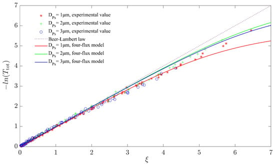
Figure 4.
Comparison of transmittance between experimental values and four-flux model prediction.
As can be seen in Figure 4, the experimental values of laser transmittance gradually deviated from the Beer–Lambert law as the optical thickness increased, even when the detector reception angle satisfied Equation (1). When the optical thickness was > 2, the difference between the experimental values of the transmittance and theoretical values based on the Beer–Lambert law started to be noticeable. This meant that the effect of multiple scattering needed to be taken into account when using the LEM for particle size measurements. However, in a similar study, Swanson et al. [33] argued that the applicability of the LEM using the Beer–Lambert theorem was < 10. A possible reason for this discrepancy was that Swanson et al. did not take into account the sedimentation of polystyrene particles in the water during the experiment, where sedimentation could result in a higher particle number density at the measurement point compared to a theoretical one. The higher particle number density resulted in a lower measured transmittance compared to the theoretical value, while in the region of greater optical thickness the presence of the multiple scattering effects resulted in a higher transmittance, and the combined effect of these two opposing effects on the transmittance ultimately resulted in the measured transmittance not being significantly different from the Beer–Lambert law.
When the optical thickness was < 4, the four-flux model agreed relatively well with the experimental transmittance values. However, as the optical thickness increased, the model’s predictions began to deviate from the experimental values. In order to make the four-flux model fit the experimental values better, a correction to could be considered; in addition, one could set as a function of , as was conducted in the reference [35], but this would complicate the problem further.
3.2. Alumina Particle Size Distribution Measurement Results
In this section, the size distribution of alumina particles, which were cured in an epoxy resin because they could not be suspended in water, are measured using the dual wavelengths, 532 nm and 1064 nm, while the extinction method and its results are compared with those measured by the Malvern laser particle size analyzer.
To invert the particle size distribution using the LEM, the extinction coefficient needed to be calculated. The complex refractive indices of the alumina for the laser lengths of 532 nm and 1064 nm ( and , respectively) for this calculation using Mie theory were [38,39]:
The extinction coefficient of alumina particles at two wavelengths of incident light versus the particle size is shown in Figure 5, which indicates that was different for different incident wavelengths and even for the same particle size.
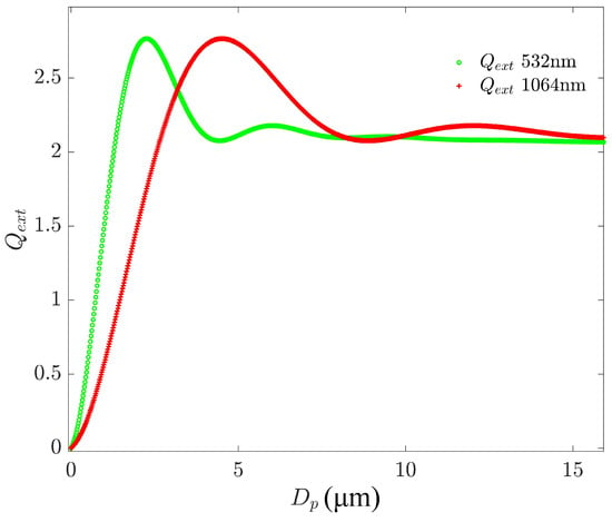
Figure 5.
varies with particle diameter for 532 and a 1064 nm wavelength lasers.
Provided that the measured particle size was polydispersed, the volume distribution functions of the particle sizes are represented as , with the total mass of the sample denoted as , the particle density denoted as , the total volume occupied by the dispersed particles in the sample denoted as , and the optical length denoted as l; then, the transmittance of the laser T was given by
where means the mass of particles per unit of dispersed volume, which could be defined as follows:
The value of the sample in Figure 3b was 0.016 mg/mL.
When the transmittance of the sample was measured at two wavelengths, the equations for are as follows:
where and are the extinction coefficients for these two wavelengths, as shown in Figure 5. and are the transmittances for the 532 nm and 1064 nm lasers, respectively. Here, the values of these two were 0.690 ± 0.0085 and 0.611 ± 0.0056, and the corresponding optical thicknesses were 0.37 and 0.49; as these two optical thickness were both less than two, the multiple scattering effects could be ignored when measuring the particle size using the LEM according to the conclusions in Section 3.1.
In theory, could be solved by Equation (23) if is a function of two parameters. The extinction coefficient is expressed in terms of the infinite series of Bessel functions, which corresponds with the integral term in Equation (23); for example, , which cannot be expressed in the primitive function form. This means that Equation (23) could not be solved directly. Here, we used the graph-plotting method to solve the system of Equation (23) through the discretization method, which converts the integral terms above into a sum containing the particle size distribution function parameters, i.e.,
where and are the two parameters of the two-parameter particle size distribution; is the incident light wavelength; and are the minimum and maximum particle sizes in the measured particle population, which can be estimated in advance; is the discrete step size; and N is the number of discrete steps:
After discretization, the left terms of Equation (23) became two functions of the particle size distribution parameter (), i.e.,
The surfaces of the functions in Equations (26) and (27) could be plotted with respect to the particle size distribution parameters; then, the intersection of these two surfaces with the plane of “Z = 0” was the solution of Equation (23).
In this paper, we selected the commonly used two-parameter particle size distributions, Rosin-Rammler (R-R) and Logarithmic-Normal (L-N) distribution, as seen in Equations (28) and (29), to describe the particle size distributions of the measured alumina powder samples.
The R-R distribution was stated as:
where the parameter k describes the distribution uniformity and is hence called the uniformity constant and is the “characteristic particle size”, defined as the size at which 63.2% of the particles (by volume) are smaller.
The L-N distribution could be stated as:
where and are the mean and standard deviation of the logarithm of the particle diameter, respectively.
The solutions of for the R-R and L-N distributions in Equation (23) for the mean transmittance at two wavelengths are shown in Figure 6, where the parameters are k = 1.392 and = 5.545 m for the R-R distribution and = 0.869 and = 4.255 m for the L-N distribution. Similarly, the particle size distribution parameters that took into account the transmittance errors could also be solved. Therefore, the measurement error could be estimated from this.
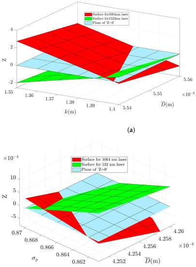
Figure 6.
Solution for obtained by plotting. (a) Solution for R-R particle size distribution. (b) Solution for L-N particle size distribution.
The comparison between the particle size measurement results of the R-R and L-N distributions obtained by the LEM and those of the Malvern laser particle size analyzer is shown in Figure 7. To view the size distribution of the small particles, the particle number probability density function (PDF) was also calculated, as shown in Figure 8.
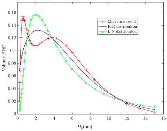
Figure 7.
The volume PDF comparison between particle size measurement results of R-R and L-N distribution obtained by the LEM and those of the Malvern laser particle size analyzer.
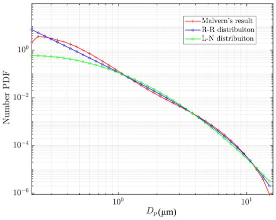
Figure 8.
The numerical PDF comparison between particle size measurement results of the R-R and L-N distribution obtained by the LEM and those of the Malvern laser particle size analyzer.
From this comparison, it was found that the two hypothetical distributions were similar to the measurements of the Malvern laser particle size analyzer.
In some applications, it was not the particle size distribution that was of interest but rather the mean particle size. The mean particle size parameters D[4, 3] and D[3, 2] of these particle size distributions and the Malvern measurements are compared in Table 2. For the higher-order mean particle sizes, the LEM particle size measurement results converged with those of the Malvern laser particle size analyzer.

Table 2.
Comparison of measurement results of LEM with that of Malvern laser particle size analyzer.
The comparisons above show that assuming a two-parameter distribution of the particle size in the sample, these results were in good agreement with those of the Malvern laser analyzer. This indicates that relatively accurate information on the particle size distribution can be obtained using only the two wavelengths of the laser transmittance data. For this particle size measurement technology, the error mainly comes from two aspects. One is the transmittance measurement error [25], which could be suppressed by rigorous calibration and careful measurements. The other error was that the true shape of the particle size distribution of the measured particle cloud could not be known, and the true shape of the particle size distribution might be multi-parametric or even mathematically rigorous [40]; therefore, there seemed to be no good way to eliminate this error.
3.3. Particle Size Measurement in SRM Plume Flames
In this section, the particle size in the SRM plume was measured using the LEM. The transmitted laser passing through flame could be received with the help of off-axis parabolic mirrors in the receiver. In this experiment, a laser was operated in pulse mode to eliminate the influence of flame radiation on the measurement results. The detector signal for the 1064 nm laser at the receiver is shown in Figure 9 when the pulsed laser transmitted the SRM plume. In Figure 9, was the detector value when there was a laser output, and was the detector value when there was no laser output, as introduced earlier. From this figure, it can be seen that the detector value was very small, at about 6 mV, and almost equal to the detector’s dark voltage, although the brightness of the SRM plume was very high. The reasons for this included the fact that there was a narrow bandpass filter in front of the detector and that the acceptance angle of the detector was very small. This resulted in a very limited effect of the SRM plume radiation on the detector at the receiver end. The effect of plume radiation could be eliminated by subtracting from . The data of the 532 nm laser was treated in the same way.
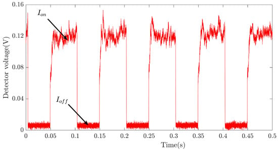
Figure 9.
Detector signal for 1064 nm laser at the receiver when the pulsed laser transmitted the SRM plume.
The transmittances in the SRM flame were measured when the SRM was in steady operation, after the effects of flame radiation were eliminated. The transmittance for the 532 nm and 1064 nm lasers was 0.205 ± 0.022 and 0.263 ± 0.012, respectively, which corresponded with the optical thickness of 1.58 and 1.34, as these two optical thicknesses were both less than two and the multiple scattering effects could be ignored when measuring particle size using the LEM according to the conclusions in Section 3.1.
As in Section 3.2, we assumed that the particle size distribution in the SRM plume flame was either an R-R or L-N distribution, and the main procedure for solving these distribution parameters by plotting was almost the same as in Section 3.2. Somewhat differently, in Equation (22) was the mass flow rate of the alumina particles of SRM, which were estimated by design parameters, and here, was:
where is the radius of the flame in the measurement area, estimated from the flame image. is the mean axial velocity of the particles in the plume flame estimated by the simulation. Moreover, l in Equation (22) was .
The solution results for R-R and L-N distributions for the mean transmittance at two wavelengths by plotting are shown in Figure 10.
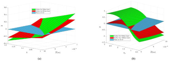
Figure 10.
Solution for of the particle in SRM plume flame by plotting. (a) Solution for R-R particle size distribution. (b) Solution for L-N particle size distribution.
According to Figure 10, the parameter k in the R-R distribution was 1.13 and was 8.32 m; the parameter in the L-N distribution was 1.51 and was 7.45 m. Based on the particle size distribution parameters solved above, the mean particle size D[3, 2] was 1.0 ± 0.3 m for the R-R distribution and 2.3 ± 0.4 m for the L-N distribution. The volume PDF of the particles in the SRM plume flame is shown in Figure 11. These measurement results indicate that when the main particle size in the SRM flame is in the order of microns, the results were in very good agreement with those reported in the references [16,41,42,43].
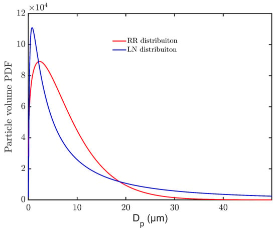
Figure 11.
Volume PDF of particles in SRM plume flame.
4. Conclusions
The LEM, based on the Beer–Lambert law, is very suitable for particle size measurements in the flame due to its non-contact measurement and relatively simple optical path arrangement. However, the Beer–Lambert law only applies if the multiple scattering effects between the particles are ignored; indeed, there is no universal conclusion under which conditions the effects of multiple scattering can be ignored, and experimental studies on this research are relatively rare. In this paper, the experimental study of the multiple scattering effect was carried out under the condition of strictly limiting the acceptance angle of the detector, and the experimental results were analyzed using a four-flux model. On this basis, the particle size distribution of the two parameters of alumina powders was measured using a two-wavelength extinction method, and the distribution equation was solved using our proposed plotting method. Finally, the particle size distribution in the SRM plume was measured. The main conclusions were as follows:
- For particle size measurements obtained using the LEM, the effect of multiple scattering could be ignored when the optical thickness was < 2 under strict restrictions on the detector acceptance angle; however, this is different from the conclusions of Swanson et al. [33], who stated that the condition for ignoring multiple scattering is an optical thickness of < 10. The reason for this difference may be that the sedimentation of particles was not considered in the experiments of Swanson et al.
- The particle size distribution of the two parameters could be solved by our proposed plotting method for a dual-wavelength LEM.
- When measuring the particle size in the flame with the LEM, the use of an off-axis parabolic mirror at the receiver suppressed the jitter of the transmitted light (Video S1), and the particle size in the plume flame of the test SRM was in the order of microns.
Supplementary Materials
The following supporting information can be downloaded at: https://www.mdpi.com/article/10.3390/en16124792/s1, Video S1: Video of an off-axis parabolic mirror suppressing laser jittering.
Author Contributions
Methodology, H.X.; Software, H.X.; Validation, B.C.; Formal analysis, H.X.; Investigation, C.Z. and W.Q.; Data curation, W.Q.; Writing—original draft, H.X.; Writing—review & editing, H.X.; Project administration, B.C.; Funding acquisition, C.Z. and W.Q. All authors have read and agreed to the published version of the manuscript.
Funding
This research was funded by the Basic National Defense Research Project, grant number JCKY2019204B020.
Data Availability Statement
The data presented in this study are available on request from the corresponding author. The data are not publicly available due to privacy.
Acknowledgments
We are deeply indebted to Haitao Xu for his advice and mentoring. Thanks to Dongwu Chang of the Department of Energy and Power Engineering at Tsinghua University for the measurements of alumina powder particle size using a Malvern laser particle size analyzer.
Conflicts of Interest
The authors declare no conflict of interest.
Abbreviations
The following abbreviations are used in this manuscript:
| CMDB | Composite-modified double base |
| DB | Double-based |
| SRM | Solid rocket motor |
| PDA | Phase Doppler Anemometry |
| LEM | Light extinction method |
| SSA | Single-scattering Approximation |
| R-R | Rosin–Rammler |
| L-N | Logarithmic–Normal |
| Probability density function |
References
- Alanen, J.; Saukko, E.; Lehtoranta, K.; Murtonen, T.; Timonen, H.; Hillamo, R.; Karjalainen, P.; Kuuluvainen, H.; Harra, J.; Keskinen, J.; et al. The formation and physical properties of the particle emissions from a natural gas engine. Fuel 2015, 162, 155–161. [Google Scholar] [CrossRef]
- Qiang Tan, P.; Yang Cao, C.; Yuan Hu, Z.; Ming Lou, D. A phenomenological model for particle number and size distributions of a diesel engine with a diesel oxidation catalyst. Sci. Total Environ. 2019, 672, 536–550. [Google Scholar]
- Wang, Q.; Sun, W.; Guo, L.; Fan, L.; Cheng, P.; Li, G.; Du, J. Particle number size distribution from direct-injection premixed combustion engine fueled with gasoline/diesel blends. Proc. Inst. Mech. Eng. Part D J. Automob. Eng. 2020, 234, 258–269. [Google Scholar] [CrossRef]
- Liu, B.; Zhang, Z.; Zhang, H.; Yang, H.; Zhang, D. An experimental investigation on the effect of convection on the ignition behaviour of single coal particles under various O2 concentrations. Fuel 2014, 116, 77–83. [Google Scholar] [CrossRef]
- Stubington, J.F.; Ng, K.W.; Moss, B.; Peeler, P.K. Comparison of experimental methods for determining coal particle devolatilization times under fluidized bed combustor conditions. Fuel 1997, 76, 233–240. [Google Scholar] [CrossRef]
- Liu, M.; Liu, Z.; Li, S.; Yu, W.; Cao, J.; Wang, N. Study on Size Distribution and Flow Characteristics of Condensed Products in Solid Rocket Motor. Int. J. Aerosp. Eng. 2021, 2021, 5481436. [Google Scholar] [CrossRef]
- Toscano, A.M.; Lato, M.R.; Fontanarosa, D.; de Giorgi, M.G. Optical diagnostics for solid rocket plumes characterization: A review. Energies 2022, 15, 1470. [Google Scholar] [CrossRef]
- Brooks, K.P.; Beckstead, M.W. Dynamics of aluminum combustion. J. Propuls. Power 1995, 11, 769–780. [Google Scholar] [CrossRef]
- Bucher, P.; Yetter, R.A.; Dryer, F.L.; Parr, T.P.; Hanson-Parr, D.M.; Viceni, E.P. Flames structure measurement of single, isolated aluminum particles burning in air. Symp. Int. Combust. 1996, 26, 1899–1908. [Google Scholar] [CrossRef]
- Hermsen, R.W. Aluminum oxide particle size for solid rocket motor performance prediction. J. Spacecr. Rocket. 1981, 18, 483–490. [Google Scholar] [CrossRef]
- Liu, M.; Yu, W.; Li, S. Factors in Condensate Product Particle Size During Aluminized Propellant Combustion. AIAA J. 2023, 1–11. [Google Scholar] [CrossRef]
- Zhu, G.; Li, J.; Li, K.; Cheng, S.; He, Z. Numerical study of the impact and aggregation characteristics of alumina droplets on a wall in the solid rocket motor. Aerosp. Sci. Technol. 2023, 137, 108242. [Google Scholar] [CrossRef]
- Gowariker, V.R. Mechanical and chemical contributions to the erosion rates of graphite throats in rocket motor nozzles. J. Spacecr. Rocket. 1966, 3, 1490–1494. [Google Scholar] [CrossRef]
- Yang, B.C.; Cheung, F.B.; Koo, J.H. Numerical investigation of thermo-chemical and mechanical erosion of ablative materials. In Proceedings of the 29th AlAA/SAE/ASME/ASEE Joint PropulsionConference and Exhibit, Monterey, CA, USA, 28–30 June 1993; pp. 1–10. [Google Scholar]
- Liggett, N.D.; Menon, S. Time-dependent nozzle erosion process in a solid propellant rocket motor. In Proceedings of the 43rd AIAA/ASME/SAE/ASEE Joint Propulsion Conference and Exhibit, Cincinnati, OH, USA, 8–11 July 2007; pp. 6222–6234. [Google Scholar]
- Saile, D.; Allofs, D.; Kühl, V.; Steffens, L.; Gülhan, A.; Beversdorff, M.; Förster, W.; Willert, C.; Carlotti, S.; Maggi, F.; et al. Characterization of SRM plumes with alumina particulate in subscale testing: Fundamental outline and first results of the ESA-EMAP project. CEAS Space J. 2021, 13, 247–268. [Google Scholar] [CrossRef]
- Horstman, M.F.; Mulrooney, M. An analysis of the orbital distribution of solid rocket motor slag. Acta Astronaut. 2009, 64, 230–235. [Google Scholar] [CrossRef]
- Balakumar, B.J.; Adrian, R.J. Particle-image velocimetry measurement in the exhaust of a solid rocket motor. Exp. Fluids 2004, 36, 166–175. [Google Scholar] [CrossRef]
- Pagliaroli, T.; Camussi, R.; Giacomazzi, E.; Giulietti, E. Velocity measurement of particles ejected from a small-size solid rocket motor. J. Propuls. Power 2015, 31, 1777–1784. [Google Scholar] [CrossRef]
- Xiao, Y.; Amano, R.S.; Cai, T.; Li, J. New method to determine the velocities of particles on a solid propellant surface in a solid rocket motor. J. Heat Transf. 2005, 127, 1057–1061. [Google Scholar] [CrossRef]
- Meierhofer, F.; Mädler, L.; Fritsching, U. Nanoparticle evolution in flame spray pyrolysis—Process design via experimental and computational analysis. AIChE J. 2020, 66, e16885. [Google Scholar] [CrossRef]
- Tischendorf, R.; Simmler, M.; Weinberger, C.; Bieber, M.; Reddemann, M.; Fröde, F.; Lindner, J.; Pitsch, H.; Kneer, R.; Tiemann, M.; et al. Examination of the evolution of iron oxide nanoparticles in flame spray pyrolysis by tailored in situ particle sampling techniques. J. Aerosol Sci. 2021, 154, 105722. [Google Scholar] [CrossRef]
- Lacoste, J.; Crua, C.; Heikal, M.; Kennaird, D.; Gold, M. PDA characterisation of dense diesel sprays using a common-rail injection system. SAE Tech. Pap. 2003, 112, 2074–2085. [Google Scholar]
- Carlotti, S.; Maggi, F. Experimental techniques for characterization of particles in plumes of sub-scale solid rocket motors. Acta Astronaut. 2021, 186, 496–507. [Google Scholar] [CrossRef]
- Eneren, P.; Aksoy, Y.T.; Zhu, Y.; Koos, E.; Vetrano, M.R. Light extinction spectroscopy applied to polystyrene colloids: Sensitivity to complex refractive index uncertainties and to noise. J. Quant. Spectrosc. Radiat. Transf. 2021, 261, 107494. [Google Scholar] [CrossRef]
- Dittmann, R.; Feld, H.; Samenfink, W.; Wittig, S. Multiple Wavelength Extinction Technique for Particle Characterization in Dense Particle Clouds. Part. Part. Syst. Charact. 1994, 11, 379–384. [Google Scholar] [CrossRef]
- Bryant, F.D.; Latimer, P. Real-time particle sizing by a computer-controlled transmittance photometer. Appl. Opt. 1985, 24, 4280–4282. [Google Scholar] [CrossRef] [PubMed]
- De Iuliis, S.; Barbini, M.; Benecchi, S.; Cignoli, F.; Zizak, G. Determination of the soot volume fraction in an ethylene diffusion flame by multiwavelength analysis of soot radiation. Combust. Flame 1998, 115, 253–261. [Google Scholar] [CrossRef]
- Kerker, M. The Scattering of Light, and Other Electromagnetic Radiation; Academic Press: New York, NY, USA, 1969. [Google Scholar]
- Bayvel, L.P.; Jones, A.R. Electromagnetic Scattering and Its Applications; Springer: London, UK, 1981. [Google Scholar]
- Mishchenko, M.I.; Liu, L.; Videen, G. Conditions of applicability of the single-scattering approximation. Opt. Express 2007, 15, 7522–7527. [Google Scholar] [CrossRef]
- Mingxu, S.; Kuangfang, R.; Grehan, G. The Affect of Light Multiple Scattering on Particle Sizing by Using Light Extinction Method. Acta Opt. Sin. 2004, 24, 696–699. [Google Scholar]
- Swanson, N.L.; Billard, B.D.; Gennaro, T.L. Limits of optical transmission measurements with application to particle sizing techniques. Appl. Opt. 1999, 38, 5887–5893. [Google Scholar] [CrossRef]
- Bohren, C.F.; Huffman, D.R. Absorption and Scattering of Light by Small Particles; Wiley: Hoboken, NJ, USA, 1998. [Google Scholar]
- Maheu, B.; Letoulouzan, J.N.; Gouesbet, G. Four-flux models to solve the scattering transfer equation in terms of Lorenz-Mie parameters. Appl. Opt. 1984, 23, 3353–3362. [Google Scholar] [CrossRef]
- Maheu, B.; Gouesbet, G. Four-flux models to solve the scattering transfer equation: Special cases. Appl. Opt. 1986, 25, 1122–1128. [Google Scholar] [CrossRef] [PubMed]
- Sultanova, N.G.; Kasarova, S.N.; Nikolov, I.D. Dispersion properties of optical polymers. Acta Phys. Pol. A 2009, 116, 585–587. [Google Scholar] [CrossRef]
- Hegedus, G.; Sarkadi, T.; Czigány, T. Analysis of the light transmission ability of reinforcing glass fibers used in polymer composites. Materials 2017, 10, 637. [Google Scholar] [CrossRef] [PubMed]
- Weber, J.; Krishnan, S.; Anderson, C.D.; Nordine, P.C. Spectral absorption of molten Aluminium Oxide from 0.385 to 0.780 micrometers. J. Am. Ceram. Soc. 1995, 78, 583–587. [Google Scholar] [CrossRef]
- Aßmann, S.; Münsterjohann, B.; Huber, F.J.; Will, S. In situ determination of droplet and nanoparticle size distributions in spray flame synthesis by wide-angle light scattering (WALS). Materials 2021, 14, 6698. [Google Scholar] [CrossRef]
- Habu, H.; Shimada, T.; Hasegawa, H. Study on Al/Al2O3 Agglomeration Particle Size Distributions for Solid Propellants. In Proceedings of the 42nd AIAA/ASME/SAE/ASEE Joint Propulsion Conference & Exhibit, Sacramento, CA, USA, 9–12 July 2006; pp. 1–6. [Google Scholar]
- Jeenu, R.; Pinumalla, K.; Deepak, D. Size distribution of particles in combustion products of aluminized composite propellant. J. Propuls. Power 2010, 26, 715–723. [Google Scholar] [CrossRef]
- Gossé, S.; Hespel, L.; Gossart, P.; Delfour, A. Morphological characterization and particle sizing of alumina particles in solid rocket motor. J. Propuls. Power 2006, 22, 127–135. [Google Scholar] [CrossRef]
Disclaimer/Publisher’s Note: The statements, opinions and data contained in all publications are solely those of the individual author(s) and contributor(s) and not of MDPI and/or the editor(s). MDPI and/or the editor(s) disclaim responsibility for any injury to people or property resulting from any ideas, methods, instructions or products referred to in the content. |
© 2023 by the authors. Licensee MDPI, Basel, Switzerland. This article is an open access article distributed under the terms and conditions of the Creative Commons Attribution (CC BY) license (https://creativecommons.org/licenses/by/4.0/).