Abstract
A radial well has a unique wellbore configuration. Fracture propagation in radial well deflagration fracturing is studied rarely. The mechanism of interaction between deflagration fractures, natural fractures, and micro-fractures is still unknown. Based on continuum mechanics, damage mechanics, and variational principles, a numerical model of fracture propagation in deflagration fracturing is established with the Hamilton principle and phase-field fracture theory. The effects of horizontal principal stress difference, natural fracture distribution, and micro-fractures around the wellbore on fracture propagation in deflagration fracturing are studied. First, when no natural fractures are developed around the radial well, fractures are initiated at both ends of the radial well. Second, when there are three natural fractures around the radial well, the created fractures have the morphology of shorter fractures in the middle and longer fractures on both sides under stress interference mechanisms. Third, a larger density of natural fractures causes obvious stress superposition, changes the initiation points of radial wells and fracture morphology, and increases fracture width and reservoir stimulation volume. Fourth, as the micro-fractures increase, their interference and induction effects on deflagration fractures are enhanced gradually, and the deflection angle of fractures increases by 38.7%. The study provides a reference for optimizing deflagration fracturing in a radial well.
1. Introduction
An ultra-short-radius radial horizontal well (abbreviated as a radial well) has superiority in the development of low-permeability and fractured reservoirs, and it is also applied in the stimulation of old oil wells. Nevertheless, the increment in oil and gas production in a radial well is not always desirable. Thus, the technology of radial well-assisted fracturing is used in the stimulation of these reservoirs. Efforts have been devoted to studying the radial well-assisted fracturing technology, and progress has been made [1,2,3,4]. Based on the radial well assisted fracturing technology, a new technology of stimulation with explosives to operate deflagration fracturing in radial wells is proposed with the aim of enhanced oil recovery. Compared with the perforated hole, a radial well has a larger length and provides a path for the transportation of high-energy fracturing materials to the far end. The drainage area and reservoir connectivity are enhanced, and oil and gas production are increased.
Currently, the artificial fracture is simulated experimentally with a true triaxial hydraulic fracturing test [5,6] and theoretically with the interface element method, extended finite element method, and discrete element method. In the interface element method, different meshing methods lead to quite different results in a case, and the initial mesh determines the fracture propagation path. Moreover, the interface element method is to insert the interface unit at the interface between the cells, and the interface unit nodes have cohesion. When the fracture criterion is reached, the interface unit fails and is disconnected. In this method, cracks can only be extended on the grid or on the grid boundaries, so the difference in mesh shape will also cause the simulated cracks to be affected by the mesh shape, which will inevitably affect the calculation results [7,8]. The extended finite element method is a method of discontinuous interface processing, and special crack tracking techniques, such as Level Sets [9] and Fast Marching [10], are used to track crack surfaces. Li et al. [11,12] consider the effects of natural fracture on fracture propagation. These methods are tedious for solving three-dimensional and multi-crack problems [13,14,15]. For the discrete element method, the advantage is to solve the problem of in-seam proppant migration [16], but there are two problems to be solved. The first is that parameter calibration is cumbersome, and more research is needed. The second is that the parameters and models used in this method are single-particle level, which often do not match the scale of macroscopic experiments that can be carried out, and the time step of the calculation is closely related to the hardness of the particles, resulting in a huge amount of calculation and high requirements for computer equipment [17,18,19]. Compared with these three methods, although the phase field method is still developing, in order to obtain accurate feature length, a sufficiently fine mesh is required, resulting in high computational costs. and the technical difficulty of describing the crack surface in an indirect way, which makes it difficult to accurately locate the crack tip [20,21]. However, with the continuous efforts of scholars at home and abroad to innovate and develop computer technology, the phase field method to simulate the formation and propagation of fracturing fractures has many advantages. The phase field method is a diffusion interface processing method. Calculation does not need explicit tracing of the crack surface, and the crack surface is obtained through the automatic evolution of order parameters. There is no need for special treatment for 3D multi-crack problems. The phase field diffusion equation can be solved by the conventional finite element method. Moreover, the phase field method has a significant advantage in the simulation of multi-fracture interactions and bifurcations. This provides a theoretical method for research on radial well deflagration fracturing. In 1998, Francfort and Marigo [22] proposed the fracture variation model based on the Griffith energy theory and introduced phase field theory into macroscopic fracture mechanics. In 2000, Bourdin and Francfort et al. [8] derived the dispersion expression of the fracture surface by introducing the order parameter, which is known as a specific numerical form of the fracture variational principle. This lays the theoretical foundation for the development of the phase field fracture model. Then, Miehe et al. derived the phase field model of fracture propagation based on thermodynamics and continuum mechanics and used the historic maximum tensile strain density field as the driving force to realize irreversible fracture propagation and algorithm decoupling of the governing equation [23,24]. Guowei Liu and Chu D et al. extended the quasi-static fracture theory to the dynamic expansion model [25,26]. However, the study on fracture propagation based on the phase field method is limited to a simple demonstration of fracture propagation and model validation, and the actual fracturing and scientific problems are not studied. In this paper, considering the horizontal principal stress difference, natural fracture distribution, and microfracture around the wellbore, the phase field method is used to simulate fracture initiation in the reservoir in deflagration fracturing, and the fracture propagation mechanism of radial well deflagration fracturing is revealed. The study provides a solution for oilfield production and reservoir stimulation.
2. Phase Field Fracture Theory and Model Verification
2.1. Phase Field Fracture Theory
In 1998, Francfort and Marigo et al. proposed the fracture variation model based on Griffith energy theory and believed that the total potential energy Π of the elastic body Ω is expressed as Equation (1) [27].
The free energy of a fracture system is composed of elastic strain energy and fracture surface energy, and crack propagation is controlled by the principle of free energy minimization. is the elastic strain energy density, is the strain tensor, u ∈ Rd (d ∈ {1, 2, 3}) is the displacement, and is the critical energy release rate of the material.
The right two terms of the equation are analyzed individually. For the linear elasticity problem, the elastic strain energy density is expressed as a product of phase field variable and linear elastic strain energy density:
where is the linear elastic strain energy density, which is expressed in classical mechanics as follows:
is the stiffness matrix of a linearly elastic material, and is the dependent variable.
where is a parabolic degradation function, is the model parameter [23], and avoids numerical singularity when .
In 2000, considering the difficulty in calculating the boundary integral in the surface energy, Bourdin and Francford et al. realized the variational criterion numerically by combining with the phase field theory and introducing the order parameter, and proposed the dispersion expression of the fracture surface [8]:
where γ is the crack surface density function, which is expressed as follows:
where γ is the area density in the integral function; is an order parameter, where 0 indicates the material is intact and 1 indicates the material is fractured completely. The dispersion width of the fracture surface is related to the parameter . The larger value of corresponds to a larger crack dispersion width, and vice versa. is a scalar field varying with time in space, i.e., the phase field expression.
By incorporating Equations (2)–(6), Equation (1) is finally written as follows:
Considering that the elastic body is damaged mostly by tensile stress in actual fracturing, it is assumed that the phase field variables only affect the tensile component of the elastic strain energy density. To prevent crack closure due to the release of elastic energy after unloading, irreversible conditions are added. Miehe et al. [23,24] proposed a simple solution to crack closure and introduced a historical state variable to prevent crack closure during elastomer compression or unloading.
The historical state variable indicates that the crack driving force is the historical maximum tensile elastic energy, and represents the elastic strain energy density generated after the object is subjected to tensile stress. Substituting elastic energy with indicates the driving force is still remained at a maximum after unloading, and this prevents crack closure. Then Equation (7) is transformed into
Meanwhile, considering the kinetic energy of the object, we have
take the first partial derivative of with respect to time , i.e., . According to the principle of analytical mechanics [28], when Newton’s second law of motion is expressed as the Hamiltonian principle, for the normalized fracture problem, the Lagrange function (L) is expressed as kinetic energy (T) minus potential energy (), i.e., .
According to the Lagrange function expression, we have
We can obtain the work done by external force:
where b and h are the body force and boundary force, respectively. The weak form can be readily obtained by taking the stationary of the Lagrangian functional . By taking the variation of the Lagrangian function L with respect to and d, i.e., , and considering at the boundary , we obtain the governing equation of the phase field fracture model in strong form:
where, denotes the phase field variable under the Laplacian operator, and the above strong form equation satisfies Neumann-type boundary conditions.
n is the normal vector outside the boundary, is the boundary condition, is Cauchy stress tensor, which is expressed by the stress tensor of undamaged solid and parabolic degradation function :
The phase field variables characterize fractures in the elastic body are shown in Figure 1.

Figure 1.
Phase field variables characterize fractures in the elastic body.
Equation (13) is a coupling form of displacement field and phase field. Furthermore, we can write the weak form of Equation (13) for solution by the finite element method:
The above equation is discretized and is calculated iteratively with the staggered method,
n is the number of element nodes, is the form function, and are the residual value (right hand side) in the process of finite element calculation.
and is a matrix composed of partial derivatives of form functions in space. For two-dimensional models, we have:
is a vector in the form function matrix, and m = 4 represents a two-dimensional model.
2.2. Numerical Model Verification
The mode I fracture of the single-edge notched tension (SENT) proposed by Philip K. Kristensen et al. [29] was simulated with the numerical model in this study. The mathematical symbol d of the phase field order parameter was used in the modeling process, which is equal to Φ in the control group. The numerical simulation results and the curves of force versus displacement are shown in Figure 2, Figure 3 and Figure 4.

Figure 2.
Simulation results in this study.
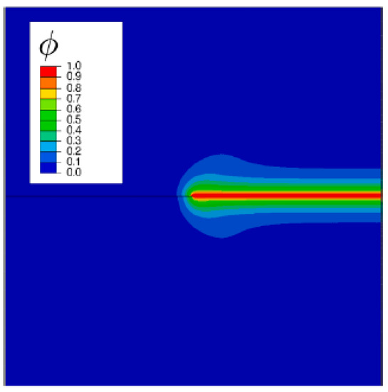
Figure 3.
Comparison test simulation results.
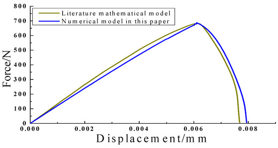
Figure 4.
Force versus displacement in a single-edged notched tension specimen.
Based on the staggered 103 increment results as a control group, it was found in comparison with simulation that the fracture morphology obtained in the model is highly consistent with that reported previously, and the stress versus displacement curves obtained from selected observation points are almost identical. Thus, the accuracy and reliability of the model are verified.
3. Analysis of Results
3.1. Establishment of Model of Radial Well Deflagration Fracturing
The characteristics of fracture initiation and propagation in radial well deflagration fracturing are studied using a 2D model. The 2D radial well geometry and parameters are shown in Figure 5. The model has a size of 20 m × 10 m, and the radial well has a length of 15m and a diameter of 0.04 m. The radial wellbore is filled with gunpowder uniformly. The radial well is meshed with 39,211 CPS4 (four-node plane stress unit) units. The reservoir has a Young’s modulus of 15 GPa and a Poisson’s ratio of 0.25. The maximum horizontal principal stress is 41 MPa in the Y direction, and the minimum horizontal ground stress is 36 MPa in the X direction. The effect of deflagration on the borehole wall is set as the surface force. According to the curve of stress and action time (p-t curve) in deflagration fracturing reported previously, the load amplitude is determined, as shown in Figure 6 [30,31]. The rock density is 2600 kg/m2, the fracture energy parameter , and the fracture characteristic length in the phase field lc = 0.5 mm. No hardening or strain penalty is applied (H = 0), and the time step is set as Δt = 103 s. The equations for the finite element model are nonlinear, and they are solved with the incremental iterative method. The model is established in commercial software such as Comsol or Abaqus, and the built-in nonlinear solver is applied. The Newton-Raphson algorithm and automatic time step scheme are applied.
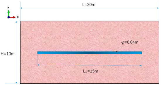
Figure 5.
Basic geometric model of radial well deflagration fracturing.
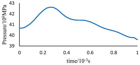
Figure 6.
Deflagration fracturing p-t curve.
Assumptions are made in modeling as follows: (i) isotropic reservoir; (ii) the effect of deflagration’s high temperature on rock properties and the pore pressure and seepage of the reservoir are ignored due to the fact that the deflagration stress acts in a very short time.
3.2. Fracture Propagation Mechanism in Deflagration Fracturing
3.2.1. Effect of Horizontal Principal Stress Difference on Fracture Propagation in Case of No Natural Fractures
The results show that when there is no natural fracture, the fracture is initiated on both ends of the radial wellbore, as shown in Figure 7. The reasons are as follows: First, the long radial wellbore provides a high-pressure channel for the deflagration of high-pressure gas. The high-pressure gas along the wellbore provides the high initial velocity and generates enough inertia and kinetic energy. The fractures are generated first on both ends of the wellbore. Secondly, there are tip stress fields on both ends of the wellbore, and stress concentration occurs. The intensity of the stress field is lower than that in other areas, likely resulting in fracture initiation on the tip.

Figure 7.
Fracture morphology in radial well deflagration fracturing without natural fractures. (a) Fracture morphology in the initial stage of deflagration fracturing; (b) Fracture morphology in the final stage of deflagration fracturing.
The effects of different horizontal principal stress differences on fracture morphology are analyzed by setting the horizontal minimum principal stress at 36 MPa and increasing the horizontal maximum principal stress at 39 MPa, 41 MPa, and 43 MPa successively. The numerical simulation results are shown in Figure 8.


Figure 8.
Effects of horizontal principal stress differences on fracture morphology. (a) Fracture propagation morphology when the horizontal principal stress difference is 3 MPa; (b) Fracture propagation morphology when the horizontal principal stress difference is 5 MPa; (c) Fracture propagation morphology when the horizontal principal stress difference is 7 MPa.
According to Figure 8, the fracture length shows a decreasing trend with an increase in the horizontal principal stress difference, and the horizontal principal stress difference has little effect on the fracture width. When the horizontal principal stress difference is 3 MPa, the fracture length is 1.80 m, and when the horizontal principal stress difference increases to 7 MPa, the fracture length is 0.55 m and decreases by 69.4%.
3.2.2. Effect of Natural Fracture Distribution on Fracture Propagation
In the actual reservoir, natural fractures or faults are possibly developed on the radial borehole wall, which affects the fracture morphology in deflagration fracturing directly. Considering the distribution of natural fractures on the cross section of a radial well, a numerical model with three natural fractures with a length of 0.5 m and a width of 0.01 m is established, and the effects of the natural fracture location on fracture propagation in deflagration fracturing are analyzed. The natural fracture spacing in the model is set at 5 m and 2.5 m, respectively. The effects of natural fractures on the fracture morphology in deflagration fracturing are shown in Figure 9.

Figure 9.
Simulation of fracture propagation under different fracture spacings. (a) natural fracture spacing of 2.5 m; (b) natural fracture spacing of 5 m.
When the natural fracture spacing is 2.5 m, communication between natural fractures occurs during fracturing, which is conducive to the formation of a fracture network structure. Nevertheless, the natural fractures have little effect on the major fractures generated on both ends of deflagration fracturing. The natural fractures, with a spacing of 5 m, are not easy to communicate. The natural fractures on both ends of the radial well are possibly communicating with the initiation points at both ends of the radial well, and this improves the stimulation volume on both ends of the radial wellbore. Moreover, it is found that the fracture morphology generated in three natural fractures is characterized by a short fracture in the middle and long fractures on two sides. This indicates the characteristics of fracture competition and stress interference. When the natural fracture spacing decreases from 5 m to 2.5 m, the natural fracture length on both sides decreases from 1.5 m to 0.8 m. The fracture width increases slightly with a decrease in fracture spacing.
3.2.3. Effect of Natural Fracture Density on Fracture Propagation
The mechanism of the effect of the natural fracture location on the fracture in deflagration fracturing was analyzed above. The effects of natural fracture density are studied here. A numerical model with different numbers of natural fractures is established, and the geometric size of natural fractures is the same as the above. The effects of natural fracture density on the fracture in deflagration fracturing are analyzed. By setting 3 natural fractures, 5 natural fractures, and 7 natural fractures evenly on the 15 m wellbore, the fracture morphology in radial well deflagration fracturing under different natural fracture densities is simulated using the established phase field model.
According to simulation results in Figure 10, with an increase in natural fractures, the fractures are more likely to communicate mutually after fracture initiation. When the outermost natural fractures are closer to the initiation points on both ends of the radial well (the distance is less than 5 m here), the major fractures in deflation fracturing are both initiated on the natural fractures on both ends, and a long fracture is generated. The fracture pressure is reduced when the natural fractures are close to the two ends of the borehole, resulting in a change in the initiation position of the radial well, and the fracture is initiated from the natural fractures first. Moreover, a larger natural fracture density leads to a larger reservoir stimulation volume near the radial well end. When the fracture density increases from 3 to 7, the total fracture length in deflagration fracturing increases from 9.2 m to 20.0 m, and the fracture width increases significantly. The initiation area in phase field d = 1 increases from 2.76 m2 to 6.01 m2. A larger density of natural fractures reduces the distance between the ends of the radial well and the natural fractures and then produces obvious stress superposition, leading to a change in the initiation point of the radial well and the fracture shape. The deflagration fracture is initiated from the natural fracture near two ends of the radial well, and the fracture width and the reservoir stimulation volume increase.
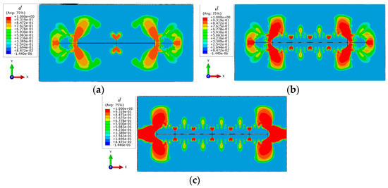
Figure 10.
Simulation of fracture propagation under different natural fracture densities. (a) Three natural fractures; (b) Five natural fractures; (c) Seven natural fractures.
3.2.4. Effect of Micro-Fracture Distribution on Fracture Propagation
Reservoir fractures, stratigraphy, or reservoir fluids can all have an impact on the form of rock mechanics and how it ruptures [32,33]. Considering the micro-fractures in the rock around the radial well, the effects of micro-fracture distribution on the deflagration fracture are analyzed. Using the established phase field model, three natural fractures with a spacing of 5 m and several micro-fractures around the wellbore are set up to simulate the characteristics of a radial well under different micro-fracture densities. The micro-fractures have a length of 0.1 m and a width of 0.001 m, and they have a cross shape. The micro-fracture has a vertical distance of 2.5 m from the radial borehole axis. In the case of multiple micro-fractures, the micro-fractures are distributed evenly among the natural fractures. The physical model is shown in Figure 11. The schemes with 2, 4, and 6 cross micro-fractures between two natural fractures are designed to analyze the mechanism of interference and the effect of micro-fractures on the deflagration fracture.

Figure 11.
Schematic of micro-fracture distribution geometric parameters. (a) 2 micro-fractures between natural fractures; (b) 4 micro-fractures between natural fractures; (c) 6 micro-fractures between natural fractures.
According to the simulation results in Figure 12, a larger micro-fracture density causes stronger interference and induction in deflagration fractures. Under simulated conditions, all micro-fractures have an effect on the stress shadow. According to the simulation results, there is a stress interference region between micro-fractures and natural fractures, and the reservoir in this region is affected by tensile stress. The phase field sequence parameter d is mostly between 0.5 and 0.9, indicating that there is a certain degree of damage in the stress shadow region and that fracture does not occur. The number of micro-fractures in the reservoir has a significant constraint on the propagation trajectory of fractures. When the number of micro-fractures increases from 4 to 12, the deflection angle of fractures increases from 31.1° to 43.1°, with an increase of 38.7%. This indicates that the fracture tends to propagate in the micro-fracture area. However, it is interesting to note that micro-fractures have no significant effect on the morphology (length and width) of the major fractures. This indicates that micro-fractures interact with natural fractures and increase the damage degree in the interaction area (d = 0.5−0.9 corresponding area), resulting in certain damage to the reservoir in this area. The number of micro-fractures has little effect on the geometry size of real fractures (corresponding area of d = 1). This indicates that in the deflagration fracturing process, the energy generated by the fuel provides the main driving force for fracture propagation, and the micro-fractures have the effect of increasing the damage degree in some areas. In the process of reservoir stimulation, attention should be paid to the effect of micro-fractures on fracture trajectory and productivity. The stress damage area can be generated by deflagration fracturing, and the reservoir is stimulated by hydraulic fracturing. This helps reduce the fracture pressure and form a volume fracture network.
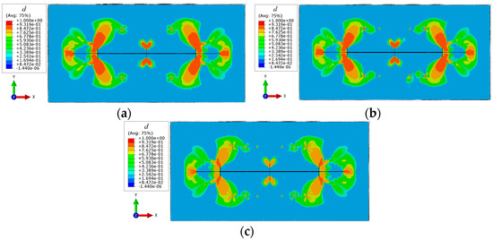
Figure 12.
Simulation of fracture propagation under different micro-fractures. (a) 2 micro-fractures between natural fractures; (b) 4 micro-fractures between natural fractures; (c) 6 micro-fractures between natural fractures.
4. Discussion
To sum up, the phase-field method is a dispersed interface processing method. The calculations do not require explicit tracing of the crack surface. More importantly, the phase field method has superiority in simulating multi-fracture interaction and bifurcation compared with the extended finite element method and interface element method. This provides a theoretical method for this study. According to the basic theory of phase fields, the fracture propagation model of deflagration fracturing is established. Based on the advantages of the phase field method, interaction and interference between fractures are studied, and some understanding is obtained. In deflagration fracturing, the high temperature generated by deflagration has a certain effect on the reservoir fluid and affects the pore pressure and seepage process. Nevertheless, considering that deflagration occurs in a very short time (less than 0.1 s) and the stress between deflagration gas and rock is derived from the high-speed pressure wave, the pore pressure, seepage, and the effect of the temperature on rock are not calculated in the mathematical model. Moreover, we notice some defects in the phase field method. For example, the model needs full grid refinement in the fracture area to solve the gradient term, which increases the workload and calculation time. Additionally, the characterization method of fracture width is still not clear and cannot be calculated theoretically, so the fracture width is analyzed and compared qualitatively. We will conduct an in-depth study on the characterization of fracture morphology in the phase field, fracture velocity prediction, and computational efficiency.
5. Conclusions
(1) When there is no natural fracture around the radial well, the fracture is initiated first on both ends of the radial well. With an increase in the horizontal principal stress difference, the fracture length decreases, and the horizontal principal stress difference has no effect on the fracture width.
(2) When there are three natural fractures with a spacing of 2.5 m in the radial well, the fracture network structure is more likely to form. Under the stress interference mechanism, the fracture morphology formed in three natural fractures is characterized by shorter fractures in the middle and longer fractures on both sides. With a decrease in natural fracture spacing, the natural fracture propagation length decreases by 46.7%.
(3) With the increase in natural fractures, the fractures are more likely to communicate mutually after fracture initiation. A larger density of natural fractures leads to obvious stress superposition, a change in the initiation point of the radial well, and a change in the fracture shape. The fracture width and the reservoir stimulation volume increase.
(4) A larger micro-fracture density causes stronger interference and induction in deflagration fractures, and the fracture deflection angle increases by 38.7%. Moreover, micro-fractures interact with natural fractures and increase the degree of damage in the interaction area, resulting in certain damage to the reservoir. However, the number of micro-fractures has little effect on the real fracture geometry.
Author Contributions
Methodology, D.G.; Software, Y.K.; Formal analysis, C.C.; Investigation, J.Z. and H.J.; Data curation, J.C.; Writing—original draft, D.G. and Y.K. All authors have read and agreed to the published version of the manuscript.
Funding
This research was funded by NSFC projects (1. Evolution mechanism and effectiveness evaluation of fracture network produced by volume fracturing with tighter clusters in continental shale oil reservoir, No. 52274040; 2. Study on thermal secondary pore evolution and salt precipitation regulation mechanism in fire flooding reservoirs based on multi-field coupling of thermal-flow-solid-chemical, No. 52274039); Shaanxi Natural Science Basic Research Program Project (Study on Liquid Propellant High Energy Gas Fracturing Mechanism in Radial Well Based on Phase Field Method. No. 2019JQ-824) and the Xi’an shiyou University school level youth scientific research and innovation team construction funds in 2018 (Flow mechanism of complex reservoirs and high efficiency development and oil production technology, No. 115080020).
Data Availability Statement
The data presented in this study are available on request from the corresponding author.
Conflicts of Interest
The authors declare no conflict of interest.
References
- Xin, J.; Shunhui, Y.; Zhiqiang, H.; Xianzhi, S.; Hongbao, Z.; Yang, C. The experimental study on the coal rock breaking efficiency of the self-rotating multi-orifice nozzle applied in URRS technique. IOP Conf. Ser. Earth Environ. Sci. 2021, 861, 062085. [Google Scholar]
- Tiankui, G.; Binyan, L.; Zhanqing, Q.; Diguang, G.; Lei, X. Study on Initiation Mechanisms of Hydraulic Fracture Guided by Vertical Multi-radial Boreholes. Rock Mech. Rock Eng. 2017, 50, 1767–1785. [Google Scholar]
- Houben, G.J.; Collins, S.; Bakker, M.; Daffner, T.; Triller, F.; Kacimov, A. Review: Horizontal, directionally drilled and radial collector wells. Hydrogeol. J. 2022, 30, 329–357. [Google Scholar] [CrossRef]
- Egberts, P.; Peters, E. Well testing of radial jet drilling wells in geothermal reservoirs. Comput. Geosci. 2022, 26, 1449–1463. [Google Scholar] [CrossRef]
- He, J.C.; Zhang, K.S.; Liu, H.B.; Tang, M.R.; Zheng, X.L.; Zhang, G.Q. Laboratory investigation on hydraulic fracture propagation in sandstone-mudstone-shale layers. Pet. Sci. 2022, 19, 1664–1673. [Google Scholar] [CrossRef]
- Abdelaziz, A.; Ha, J.; Li, M.; Magsipoc, E.; Sun, L.; Grasselli, G. Understanding hydraulic fracture mechanisms: From the laboratory to numerical modelling. Adv. Geo-Energy Res. 2023, 7, 66–68. [Google Scholar] [CrossRef]
- Song, J.H.; Wang, H.; Belytschko, T. A comparative study on finite element methods for dynamic fracture. Comput. Mech. 2008, 42, 239–250. [Google Scholar] [CrossRef]
- Bourdin, B.; Francfort, G.A.; Marigo, J.J. Numerical experiments in revisited brittle fracture. J. Mech. Phys. Solids 2000, 48, 797–826. [Google Scholar] [CrossRef]
- Gravouil, A.; Moës, N.; Belytschko, T. Non-planar 3D crack growth by the extended finite element and level sets-Part II: Level set update. Int. J. Numer. Methods Eng. 2002, 53, 2569–2586. [Google Scholar] [CrossRef]
- Sukumar, N.; Chopp, D.L.; Béchet, E.; Moës, N. Three-dimensional non-planar crack growth by a coupled extended finite element and fast marching method. Int. J. Numer. Methods Eng. 2008, 76, 727–748. [Google Scholar] [CrossRef]
- Li, J.; Dong, S.; Hua, W.; Li, X.; Pan, X. Numerical investigation of hydraulic fracture propagation based on cohesive zone model in naturally fractured formations. Processes 2019, 7, 28. [Google Scholar] [CrossRef]
- Li, J.; Hua, W.; Tang, H.; Huang, J.; Dong, S. Stress intensity factors and T-stress for an edge cracked Brazilian disk specimen under diametrically distributed load. Theor. Appl. Fract. Mech. 2022, 120, 103402. [Google Scholar] [CrossRef]
- Menouillard, T.; Belytschko, T. Dynamic fracture with meshfree enriched XFEM. Acta Mech. 2010, 213, 53–69. [Google Scholar] [CrossRef]
- Xu, D.; Liu, Z.; Liu, X.; Zeng, Q.; Zhuang, Z. Modeling of dynamic crack branching by enhanced extended finite element method. Comput. Mech. 2014, 54, 489–502. [Google Scholar] [CrossRef]
- Belytschko, T.; Chen, H.; Xu, J.; Zi, G. Dynamic crack propagation based on loss of hyperbolicity and a new discontinuous enrichment. Int. J. Numer. Methods Eng. 2003, 58, 1873–1905. [Google Scholar] [CrossRef]
- Guo, T.K.; Luo, Z.L.; Zhou, J.; Gong, Y.Z.; Dai, C.L.; Tang, J.; Yu, Y.; Xiao, B.; Niu, B.L.; Ge, J.J. Numerical simulation on proppant migration and placement within the rough and complex fractures. Pet. Sci. 2022, 19, 2268–2283. [Google Scholar] [CrossRef]
- Wu, S.; Xu, X. A study of three intrinsic problems of the classic discrete element method using flat-joint model. Rock Mech. Rock Eng. 2015, 49, 1813–1830. [Google Scholar] [CrossRef]
- Chen, F.; Li, Y.; Shi, T.; Yan, H. Numerical Simulation of Full Phases of Collapse of Three-dimensional Cylindrical Granular Pile. Chin. J. Theor. Appl. Mech. 2022, 54, 1572–1589. [Google Scholar]
- Ilyushin, Y.V.; Asadulagi, M.A.M. Development of a Distributed Control System for the Hydrodynamic Processes of Aquifers, Taking into Account Stochastic Disturbing Factors. Water 2023, 15, 770. [Google Scholar] [CrossRef]
- Wu, J.Y.; Nguyen, V.P.; Nguyen, C.T.; Sutula, D.; Sinaie, S.; Bordas, S.P. Chapter one-phase-field modeling of fracture. Adv. Appl. Mech. 2020, 53, 1–183. [Google Scholar]
- Diehl, P.; Lipton, R.; Wick, T.; Tyagi, M. A comparative review of peridynamics and phase-field models for engineering fracture mechanics. Comput. Mech. 2022, 69, 1259–1293. [Google Scholar] [CrossRef]
- Francfort, G.A.; Marigo, J.J. Revisiting brittle fracture as an energy minimization problem. J. Mech. Phys. Solids 1998, 46, 1319–1342. [Google Scholar] [CrossRef]
- Miehe, C.; Welschinger, F.; Hofacker, M. Thermodynamically consistent phase-field models of fracture: Variational principles and multi-field FE implementations. Int. J. Numer. Methods Eng. 2010, 83, 1273–1311. [Google Scholar] [CrossRef]
- Miehe, C.; Hofacker, M.; Welschinger, F. A phase field model for rate-independent crack propagation: Robust algorithmic implementation based on operator splits. Comput. Methods Appl. Mech. Eng. 2010, 199, 2765–2778. [Google Scholar] [CrossRef]
- Liu, G.; Li, Q.; Msekh, M.A.; Zuo, Z. Abaqus implementation of monolithic and staggered schemes for quasi-static and dynamic fracture phase-field model. Comput. Mater. Sci. 2016, 121, 35–47. [Google Scholar] [CrossRef]
- Chu, D.; Li, X.; Liu, Z. Study the dynamic crack path in brittle material under thermal shock loading by phase field modeling. Int. J. Fract. 2017, 208, 115–130. [Google Scholar] [CrossRef]
- Liu, G.; Li, Q.; Zuo, Z. Implementation of a staggered algorithm for a phase field model in ABAQUS. Chin. J. Rock Mech. Eng. 2016, 35, 1019–1030. [Google Scholar]
- Liang, K. Mechanics; Higher Education Press: Beijing, China, 1995. [Google Scholar]
- Kristensen, P.K.; Martínez-Pañeda, E. Phase field fracture modelling using quasi-Newton methods and a new adaptive step scheme. Theor. Appl. Fract. Mech. 2020, 107, 137–144. [Google Scholar] [CrossRef]
- Li, L.; Zhang, T. Estimation of HEGF Crack Length Using Measured P-t Curves. In Proceedings of the Theory and Practice of Rock Crushing—Selected Papers from the Fifth National Symposium on Rock Crushing, Xi’an, China, September 1992; pp. 291–296. [Google Scholar]
- Cai, W.; Liu, Y.; Lv, S. Influence of firing-circuitry polarity to igniter p-t curve. Aero Weapon. 2005, 06, 47–49. [Google Scholar]
- Martirosyan, A.V.; Ilyushin, Y.V. The Development of the Toxic and Flammable Gases Concentration Monitoring System for Coalmines. Energies 2022, 15, 8917. [Google Scholar] [CrossRef]
- Makarova, A.A.; Kaliberda, I.V.; Kovalev, D.A.; Pershin, I.M. Modeling a Production Well Flow Control System Using the Example of the Verkhneberezovskaya Area. In Proceedings of the 2022 Conference of Russian Young Researchers in Electrical and Electronic Engineering (ElConRus), Saint Petersburg, Russia, 25–28 January 2022; pp. 760–764. [Google Scholar]
Disclaimer/Publisher’s Note: The statements, opinions and data contained in all publications are solely those of the individual author(s) and contributor(s) and not of MDPI and/or the editor(s). MDPI and/or the editor(s) disclaim responsibility for any injury to people or property resulting from any ideas, methods, instructions or products referred to in the content. |
© 2023 by the authors. Licensee MDPI, Basel, Switzerland. This article is an open access article distributed under the terms and conditions of the Creative Commons Attribution (CC BY) license (https://creativecommons.org/licenses/by/4.0/).