
Application of Phase-Shifting Transformer with Longitudinal and Transverse Voltage Regulation

 ,
,  and
and
Abstract
:1. Introduction
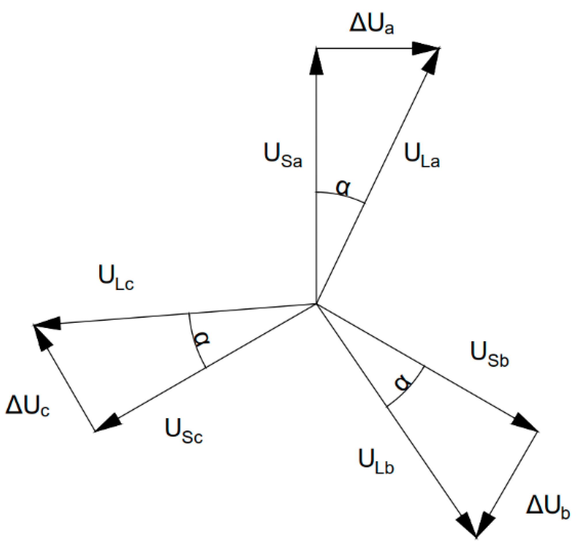
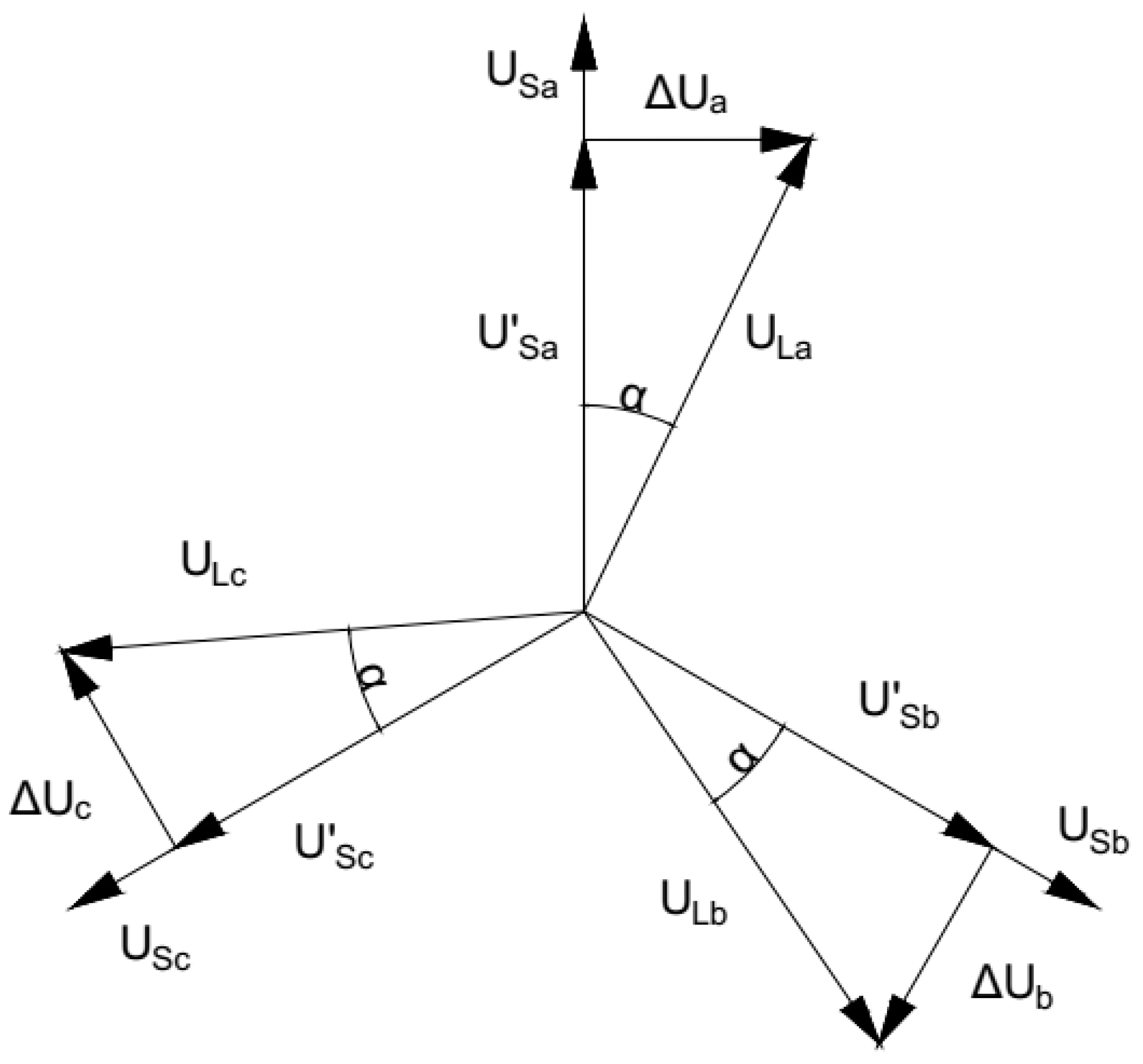
2. APST and ACPST Description
3. Materials and Methods
3.1. Laboratory Setup
3.2. Power Flow Simulations
4. Laboratory Tests
5. Power Flow Calculations
6. Conclusions
Author Contributions
Funding
Conflicts of Interest
References
- Shalukho, A.V.; Lipuzhin, I.A.; Voroshilov, A.A. Power Quality in Microgrids with Distributed Generation. In Proceedings of the 2019 International Ural Conference on Electrical Power Engineering (UralCon), Chelyabinsk, Russia, 1–3 October 2019; pp. 54–58. [Google Scholar] [CrossRef]
- Mozina, C.J. Impact of Green Power Distributed Generation. IEEE Ind. Appl. Mag. 2010, 16, 55–62. [Google Scholar] [CrossRef]
- Strezoski, L.; Stefani, I.; Brbaklic, B. Active management of distribution systems with high penetration of distributed energy resources. In Proceedings of the 18th International Conference on Smart Technologies, Novi Sad, Serbia, 1 July 2019; pp. 1–5. [Google Scholar]
- Korab, R.; Owczarek, R. Kształtowanie transgranicznych przepływów mocy z wykorzystaniem przesuwników fazowych. Rynek Energii 2012, 5, 8–15. [Google Scholar]
- Bieroński, S.; Korab, R.; Owczarek, R. Wpływ regulacji przesuwników fazowych instalowanych w rejonie Europy Środkowo-Wschodniej na transgraniczne przepływy mocy. Prace Naukowe Politechniki Śląskiej. Elektryka 2015, 61, 7–22. [Google Scholar]
- Verboomen, J.; Van Hertem, D.; Schavemaker, P.H.; Kling, W.L.; Belmans, R. Phase shifting transformers: Principles and applications. In Proceedings of the 2005 International Conference on Future Power Systems, Amsterdam, The Netherlands, 16–18 November 2005; p. 6. [Google Scholar]
- Van Hertem, D.; Eriksson, R.; Söder, L.; Ghandhari, M. Coordination of multiple power flow controlling devices in transmission systems. In Proceedings of the 9th IET International Conference on AC and DC Power Transmission (ACDC 2010), London, UK, 19–21 October 2010; pp. 1–6. [Google Scholar] [CrossRef]
- Bresesti, P.; Sforna, M.; Allegranza, V.; Canever, D.; Vailati, R. Application of phase shifting transformers for a secure and efficient operation of the interconnection corridors. In Proceedings of the IEEE Power Engineering Society General Meeting, Denver, CO, USA, 6–10 June 2004; Volume 2, pp. 1192–1197. [Google Scholar] [CrossRef]
- Morrell, T.J.; Eggebraaten, J.G. Applications for Phase-Shifting Transformers in Rural Power Systems. In Proceedings of the 2019 IEEE Rural Electric Power Conference (REPC), Bloomington, MN, USA, 28 April–1 May 2019; pp. 70–74. [Google Scholar] [CrossRef]
- Schmidt, T. ABB AG Transformers. In Phase-Shifting Transformers Applications and Technology; ABB Group, 2016. [Google Scholar]
- ENTSO-E. Regional Investment Plan CCE. In Draft Version Prior to Public Consultation; ENTSOE: Brussel, Belgium, 2020. [Google Scholar]
- Polster, S.; Renner, R. Generalisation of the Line Outage Distribtution Factors on Phase Shifting Transformers. In Proceedings of the 53rd International Universities Power Engineering Conference (UPEC), Glasgow, UK, 4–7 September 2018; pp. 1–6. [Google Scholar] [CrossRef]
- Sosnina, E.; Loskutov, A.; Asabin, A.; Bedretdinov, R.; Kryukov, E. Power flow control device prototype tests. In Proceedings of the 2016 IEEE Innovative Smart Grid Technologies—Asia (ISGT-Asia), Melbourne, VIC, Australia, 28 November–1 December 2016; pp. 312–316. [Google Scholar] [CrossRef]
- McMillan, B.; Guido, P.; Leitermann, O.; Martinelli, V.; Gonzaga, A.; McFetridge, R. Application of Power Electronics LV Power Regulators in a Utility Distribution System. In Proceedings of the 2015 IEEE Rural Electric Power Conference, Asheville, NC, USA, 19–21 April 2015; pp. 43–47. [Google Scholar] [CrossRef]
- Hadzimuratovic, S.; Fickert, L. Determination of critical factors for optimal positioning of Phase-Shift Transformers in interconnected systems. In Proceedings of the 19th International Scientific Conference on Electric Power Engineering (EPE), Brno, Czech Republic, 16–18 May 2018; pp. 1–6. [Google Scholar] [CrossRef]
- Brilinskii, A.S.; Badura, M.A.; Evdokunin, G.A.; Chudny, V.S.; Mingazov, R.I. Phase-Shifting Transformer Application for Dynamic Stability Enhancement of Electric Power Stations Generators. In Proceedings of the IEEE Conference of Russian Young Researchers in Electrical and Electronic Engineering (EIConRus), St. Petersburg/Moscow, Russia, 27–30 January 2020; pp. 1176–1178. [Google Scholar] [CrossRef]
- Ding, T.; Bo, R.; Bie, Z.; Wang, X. Optimal selection of phase shifting transformer adjustment in optimal power flow. IEEE Trans. Power Syst. 2017, 32, 2464–2465. [Google Scholar] [CrossRef]
- Korab, R.; Połomski, M.; Owczarek, R. Application of particle swarm optimization for optimal setting of Phase Shifting Transformers to minimize unscheduled active power flows. Appl. Soft Comput. 2021, 105, 107243. [Google Scholar] [CrossRef]
- Ashpazi, M.A.; Mohammadi-Ivatloo, B.; Zare, K.; Abapour, M. Probabilistic allocation of thyristor-controlled phase shifting transformer for transient stability enhancement of electric power system. IETE J. Res. 2015, 61, 382–391. [Google Scholar] [CrossRef]
- Albrechtowicz, P.; Szczepanik, J. The Comparative Analysis of Phase Shifting Transformers. Energies 2021, 14, 4347. [Google Scholar] [CrossRef]
- Ziemianek, S. Model matematyczny zespołu transformatorowego z trapezoidalnym zakresem regulacji przekładni zespolonej do analiz ustalonych i quasi-ustalonych stanów pracy symetrycznych fazowo. Przegląd Elektrotech. 2013, 89, 143–151. [Google Scholar]
- Sen, K.K.; Sen, M.L. Comparison of the Sen transformer with the unified power flow controller. IEEE Trans. Power Deliv. 2003, 18, 1523–1533. [Google Scholar] [CrossRef]
- Sen, K.K.; Sen, M.L. Versatile Power Flow Transformers for Compensating Power Flow in a Transmission Line. Patent No. US6420856B1, 16 July 2002. [Google Scholar]
- Sen, K.K.; Sen, M.L. Versatile Power Flow Transformers for Compensating Power Flow in a Transmission Line. Patent No. US6384581B1, 7 May 2002. [Google Scholar]
- Machowski, J.; Lubośny, Z. Stabilność Systemu Elektroenergetycznego; Wydawnictwo WNT: Warsaw, Poland, 2018. [Google Scholar]
- Żurek, S.; Przygrodzki, M. The Use of a Regulating Transformer for Shaping Power Flow in the Power System. Energies 2023, 16, 1548. [Google Scholar] [CrossRef]
- Albrechtowicz, P. Phase-Shifting Transformer Efficiency Analysis Based on Low-Voltage Laboratory Units. Energies 2021, 14, 5049. [Google Scholar] [CrossRef]
- Szczepanik, J.; Rozegnał, B. The development of the real life model of the five node power system, Czasopismo Techniczne. Elektrotechnika 2015, 112, 83–102. [Google Scholar]
- Zimmerman, R.D.; Murillo-Sanchez, C.E. MATPOWER User’s Manual; Version 7.1; 2020. [Google Scholar] [CrossRef]
- Machowski, J. Regulacja Systemu Elektroenergetycznego; Oficyna Wydawnicza Politechniki Warszawskiej: Warsaw, Poland, 2017. [Google Scholar]
- Kanicki, A. Systemy Elektroenergetyczne. Available online: http://www.ssdservice.pl/FTPserwer/ELEKTROTECHNIKA/systemy/systemy%20roz.%203.pdf (accessed on 22 March 2022).


| Series Transformer ST | Extra Transformer ET | |
|---|---|---|
| Rated Primary Voltage, V | 3 × 400 | 3 × 400 |
| Rated Secondary voltage, V | 3 × 128/3 × 64/3 × 32/3 × 16/3 × 8/3 × 4 | 3 × 400 +5 × 1.5% or −10 × 1.5% |
| Rated Primary Current, A | 3 × 33.2 | 3 × 33 |
| Rated Secondary Current, A | 3 × 30/3 × 30/3 × 30/ 3 × 30/3 × 30/3 × 30 | 3 × 32.5 |
| Rated Power, kVA | 22.5 | 22.5 |
| Rated Frequency, Hz | 50 | 50 |
| Connection Group | D/iiiiii | Yy0 |
| Short-Circuit Voltage, % | 3.88 | 5.10 |
| Bus | Bus Type | Power Demanded MVA | Power Generated MVA | Voltage Pu |
|---|---|---|---|---|
| 1 | Slack bus | 150 + j50 | 0 | 1 |
| 2 | PQ | 100 + j40 | 0 | Var |
| 3 | PV | 90 | 200 + j75 | 1.06 |
| 4 | PQ | 180 + j100 | 0 | Var |
| 5 | PV | 0 | 360 + j65 | 1.06 |
| ET Ratio | 400/376 | 400/340 |
|---|---|---|
| US, V | 230.3 | 208.4 |
| ΔU, V | 65.8 | 65.8 |
| UL, V | 239.5 | 218.5 |
| α, ° | −16 | −18 |
| Voltage [kV] | Angle [°] | Voltage [kV] | Angle [°] | Voltage [kV] | Angle [°] | |
|---|---|---|---|---|---|---|
| Set phase shift | 5° | 10° | 15° | |||
| APST | 412.4 | 1.16 | 413.2 | 2.21 | 414.4 | 3.17 |
| ACPST QS | 411.6 | 0.94 | 410.8 | 1.92 | 409.2 | 2.88 |
| ACPST η > 1 | 403.2 | 1.03 | 403.6 | 2.02 | 404.4 | 2.91 |
| Voltage [kV] | Angle [°] | Voltage [kV] | Angle [°] | Voltage [kV] | Angle [°] | |
|---|---|---|---|---|---|---|
| APST | 5° | 10° | 15° | |||
| 412.4 | 1.16 | 413.2 | 2.21 | 414.4 | 3.17 | |
| ACPST QS | 6.2° | 12.1° | 17.9° | |||
| 411.6 | 1.19 | 408.4 | 2.30 | 406.0 | 3.37 | |
| ACPT η > 1 | 6.6° | 12.2° | 18° | |||
| 403.2 | 1.36 | 403.6 | 2.43 | 404.8 | 3.41 | |
| ΔP, MW | ΔQ, MVAr | ΔP, MW | ΔQ, MVAr | ΔP, MW | ΔQ, MVAr | |
|---|---|---|---|---|---|---|
| APST | 5° | 10° | 15° | |||
| 8.1 | 47.8 | 13.4 | 83.1 | 22.2 | 140.9 | |
| ACPST QS | 5° | 10° | 15° | |||
| 7.1 | 47.3 | 11.4 | 77.8 | 18.4 | 127.7 | |
| 6.2° | 12.1° | 17.9° | ||||
| 7.8 | 42.9 | 19.5 | 95.0 | 33.1 | 163.9 | |
| ACPST η > 1 | 5° | 10° | 15° | |||
| 8.9 | 47.2 | 15.4 | 76.9 | 25.8 | 125.5 | |
| 6.6° | 12.2° | 18° | ||||
| 10.7 | 54.6 | 19.5 | 96.0 | 33.1 | 163.9 | |
Disclaimer/Publisher’s Note: The statements, opinions and data contained in all publications are solely those of the individual author(s) and contributor(s) and not of MDPI and/or the editor(s). MDPI and/or the editor(s) disclaim responsibility for any injury to people or property resulting from any ideas, methods, instructions or products referred to in the content. |
© 2023 by the authors. Licensee MDPI, Basel, Switzerland. This article is an open access article distributed under the terms and conditions of the Creative Commons Attribution (CC BY) license (https://creativecommons.org/licenses/by/4.0/).
Share and Cite
Albrechtowicz, P.; Rozegnał, B.; Szczepanik, J.; Sułowicz, M.; Cisek, P. Application of Phase-Shifting Transformer with Longitudinal and Transverse Voltage Regulation. Energies 2023, 16, 4603. https://doi.org/10.3390/en16124603
Albrechtowicz P, Rozegnał B, Szczepanik J, Sułowicz M, Cisek P. Application of Phase-Shifting Transformer with Longitudinal and Transverse Voltage Regulation. Energies. 2023; 16(12):4603. https://doi.org/10.3390/en16124603
Chicago/Turabian StyleAlbrechtowicz, Paweł, Bartosz Rozegnał, Jerzy Szczepanik, Maciej Sułowicz, and Piotr Cisek. 2023. "Application of Phase-Shifting Transformer with Longitudinal and Transverse Voltage Regulation" Energies 16, no. 12: 4603. https://doi.org/10.3390/en16124603
APA StyleAlbrechtowicz, P., Rozegnał, B., Szczepanik, J., Sułowicz, M., & Cisek, P. (2023). Application of Phase-Shifting Transformer with Longitudinal and Transverse Voltage Regulation. Energies, 16(12), 4603. https://doi.org/10.3390/en16124603