Article

Identifying the Active Species in Li-Na Dual-Ion “Saltwater Battery” Based on Spinel Lithium Manganese Oxide, Sodium Titanium Phosphate and Aqueous Electrolyte

1
Technology Center for Energy, University of Applied Science Landshut, Wiesenweg 1, 94099 Ruhstorf a.d. Rott, Germany
2
Heinz-Mayer Leibnitz Zentrum (MLZ), Technical University Munich (TUM), Lichtenbergstraße 1, 85748 Garching, Germany
3
Chair of Electrical Energy Systems, University of Bayreuth, Universitätsstraße 30, 95447 Bayreuth, Germany
*
Author to whom correspondence should be addressed.
Energies 2023, 16(11), 4485; https://doi.org/10.3390/en16114485
Submission received: 8 May 2023 / Revised: 25 May 2023 / Accepted: 27 May 2023 / Published: 1 June 2023
(This article belongs to the Section D2: Electrochem: Batteries, Fuel Cells, Capacitors)

Abstract

:
The dual-ion “Saltwater Battery” based on aqueous electrolyte containing sodium ions and lithium ions is believed to be one of the safest and environmentally friendliest battery technologies. The anode consists of sodium titanium phosphate, whereas the cathode is spinel lithium manganese oxide. It has been reported that both materials can intercalate sodium and lithium ions depending on their availability in the electrolyte. This study aims to identify the dominant active species in “Saltwater Batteries” with dual-ion electrolyte. Therefore, cyclic voltammetry of single electrodes as well as full cell measurements are performed with electrolyte containing lithium sulfate, sodium sulfate or a mixture. Moreover, the study is complemented by ion analysis of the electrolyte, as well as X-ray diffraction of fresh and cycled electrodes at different states of charge. The results show that the cathode only (de)intercalates lithium ions, revealing that Li is the dominant active cathode species. The anode can react with both ions and undergoes a formation reaction accompanied by partial dissolution of sodium titanium phosphate. Nevertheless, cyclic voltammetry and full cell measurements indicate that lithium is also the dominant active species on the anode side. In conclusion, the dual-ion battery is dominated by lithium and shows a superior performance when removing sodium from electrolyte.

1. Introduction

The rapid increase in energy prices as well as climate change have led to a boom in the use of energy storage systems for household applications. The increased self-sufficiency and independence of power grids are strong arguments for investments in home storage systems.
Today, lithium-ion batteries (LIBs) are the most available and commercialized home storage solution. Remaining safety issues and critical material supply chains require further improvements in energy storage systems. Currently, LIBs are irreplaceable for mobile applications due to their unrivaled high energy and power density. In contrast, stationary storage systems have other requirements, consequently enabling different technologies to enter the market. Size, volume and weight, and thus specific energy and power density, are less important. Safety issues and environmental impact receive more attention as well as the material availability (resource self-sufficiency). Additionally, redox-flow batteries [1], potassium-ion batteries [2,3], bimetallic-sulfide batteries [4], sodium-ion batteries [3,5] and dual-ion batteries [6] have drawn more attention to fulfil safety, environmental and material requirements with a sufficient energy density. Research includes dual-ion systems based on cations/anions, such as hybrid cathodes for LIBs [7], sodium bromide [8] or sodium fluoride [9], as well as dual-cation technologies, such as lithium-sodium dual-ion batteries [10]. The aim of the latter battery type is to combine the benefits of lithium regarding its capacity with the advantages of sodium regarding its material abundance. Research has been performed on organic-based Li-Na dual-ion batteries [11] as well as aqueous-based systems [10,12]. The development of aqueous-based systems includes intrinsic advantages regarding toxicity, costs, and flammability.
In the last decade, research has led to the development of the commercially available “Saltwater Battery” for stationary applications as an alternative to LIBs [10,12]. The technology is based on aqueous electrolyte, a lithium manganese spinel cathode and a sodium titanium phosphate anode [10,13]. Thus, it is a dual-ion system containing lithium (cathode) and sodium (anode) ions. Both ions are also part of the electrolyte. In contrast to the organic solvents used in most LIBs, water functions as a solvent and the basis for ion transport. Sodium sulfate and lithium sulfate act as conducting salts in order to deliver both species for the dual-ion battery type [10,13]. Notably, the ionic transfer in aqueous solutions can exceed that of organic electrolytes significantly [14]. The aqueous electrolyte also leads to a wide range of possible separators, such as synthetic cotton, due to fewer requirements according to the chemical stability [10,14].
The electrodes are multicomponent systems, as in conventional LIBs. Two additives, graphite and carbon black, with different particle sizes and thus various lengths of conductive connections between the grains of active materials are used. Due to the thickness of the electrodes being above 1 mm, these conductive agents play a major role in the performance of the cells [10]. For the “Saltwater Battery”, polytetrafluoroethylene works as a binder. It performs well within this dual-ion system [15]. Since aqueous electrolyte can become acidic or alkaline during cell operation, at least locally for a short time, stainless steel collectors of types 1.4301 or 1.4404 [10,15] are the most prominent in “Saltwater Technology”.
The active materials of the cathode and anode are spinel lithium manganese oxide LiMn2O4 (LMO) and sodium titanium phosphate NaTi2(PO4)3 (NTP). Both phases have been reported to work successfully as the host structure for reversible ion intercalation in aqueous-based electrolyte containing lithium and sodium ions with a beneficial ecological impact [10,16]. Other commonly known active materials, such as lithium iron phosphate or cobalt nickel manganese oxides cannot be used in this dual-ion battery type due to their sensitivity to water. Exemplary SEM pictures of the used LMO and NTP can be found in the supplementary material (Figure S9 and Figure S10). Due to benefits regarding its lifetime, electrical conductivity, and surface structure, NTP is coated with carbon (NaTiPO), as reported by several groups [15,17,18,19,20]. Additionally, the anode contains a fifth compound: activated carbon [10,13]. Previous studies [10,13] have shown that activated carbon with a high surface area is beneficial for the reaction environment, resulting in enhanced cycle stability. The resulting electrode formulations in our work are summarized in Table 1.
The working principle of the active materials in the used electrodes is described as an intercalation process [10,21,22]. There are different studies in which a manganese oxide structure has worked as a host for sodium ions [5,9,12,15,17,18,20,21,23,24,25,26,27] or for lithium ions [8,12,14,16,19,22,28,29], depending on the selected electrolyte and thus the available ion. Whitacre et al. [10] assumed that the cathode is interacting with both ions during operation. They mentioned that lithium containing manganese spinel changes to a λ-manganese phase with empty space for sodium ions. Nevertheless, lithium intercalation is likely to be preferred due to its smaller ionic radius [10,25].
Similarly, the charging mechanism of the NaTiPO anode is based on intercalation. Comparably to the cathode material, some groups have described lithium titanium phosphate in a lithium environment intercalation process (Equation (1)) [10,12,15,20,28], whereas others have described the intercalation process based on a sodium environment for the isostructural sodium titanium phosphate (Equation (2)) [10,12,15,18,20,24].
LiTi2(PO4)3 → Li1+xTi2(PO4)3 (0 ≤ x ≤ 2)
NaTi2(PO4)3 → Na1+xTi2(PO4)3 (0 ≤ x ≤ 2)
Sun et al. [19] presented the benefits of using sodium titanium phosphate in a lithium environment showing lower material costs and more space for lithium ions. In this environment, the material can host both ions during the two-step intercalation process. Wang et al. [8] described the chemical process as the mixed uptake of sodium and lithium (Equation (3)):
NaTi2(PO4)3 → Na1−xLiyTi2(PO4)3 (0 ≤ x ≤ 1; 0 ≤ y ≤ 3)
Chen et al. [30] showed that total or partial ion exchange happens when NaTiPO or LiTiPO is cycled in electrolytes containing the other species.
To summarize, several groups have described the ability of LMO as well as NaTiPO to work as a host for Li ions as well as Na ions, depending on the used electrolyte. However, the preferred active ion for a battery system using Li-Na dual-ion electrolyte, such as the analyzed system, remains unclear. Therefore, this study aimed to analyze this commercially available “Saltwater Battery” working principle based on the given electrode and electrolyte formulation to identify the active ions for each electrode. The results should be used in future work on target-oriented development to increase the capacity, e.g., via material selection or variation of the electrode formulation. Herein, we focused on single electrodes to investigate the active species by cyclic voltammetry (CV) as well as X-ray diffraction (XRD). Additionally, we performed full cell measurements with electrolytes containing only one ion type to analyze the performance by exclusion. Finally, an ion analysis of the electrolyte regarding sodium and lithium ions at different states of charge (SoC) was performed to give further insight into the behavior of the active ions.

2. Experimental

In the following, the necessary electrode as well as the electrolyte preparation are described. Afterwards, the experimental setup and execution of the above-mentioned measurements are presented.

2.1. Electrode Preparation

For CV, a few mg (<50 mg) of material was used to prepare electrode samples. Material details are summarized in Table 2. The electrode mixture was prepared solvent-free with a mortar and pestle for both the anode and cathode. By mixing for 10 min, an optically homogenous electrode mixture was produced.
The mixtures were pressed with a manual hydraulic garage press into a stainless steel 1.4404 wire cloth with a 60 × 60 mesh type and a thickness of 50 µm. The electrode was 0.5 × 0.5 cm2 in size and was pressed with 8 metric tons into the mesh. The final electrode weight was 25 mg.
For full cells, from which the samples for XRD were also extracted, the same materials with the same composition were used for electrodes. Here, we used two-stage mixing with a highly intensive mixer (El1, Eirich, Hardheim, Germany). At first, active materials and conductive additives were mixed for 7.5 min. Secondly, a binder was added, and mixing continued for another 8 min. The procedure remained the same for the anode and cathode. Afterwards, the electrode powder mixture was laminated onto the current collector, which was a primer-coated stainless steel 1.4301 sheet (50 µm thick, MK Metallfolien, Hagen, Germany). Lamination was performed with a roller press laminator (KFK-L 600, Maschinenfabrik Herbert Meyer, Rötz, Germany) under conditions of 190 °C and 40 kN/cm2. The final electrodes had a size of 4.5 × 5.5 cm2 with thicknesses of 1.3 mm and 1.4 mm for the cathode and anode, respectively. The mass ratio of the cathode to the anode was 1.4:1.0, resulting in a capacity balance of 1.2:1.0.

2.2. Electrolyte Preparation

The electrolyte required for the measurements was mixed with a magnetic stirrer and agitator. The solvent was deionized water, and the salts were added during mixing. Stirring for 15 min dissolved the salt completely under ambient conditions. Depending on the measurement, 10 wt.% sodium sulfate (Purity ≥ 99.9%, CALC, Brenntag, Wien, Austria), 10 wt.% lithium sulfate (Purity ≥ 99.0%, Anhydrous Technical, Interchim, Wörgl, Austria) or 10 wt.% of both salts (resulting in 20 wt.% total salt) were added.

2.3. Cyclic Voltammetry

The CV measurements were performed with a potentiostat (VMP3, Biologic, Seyssinet-Pariset, France). Therefore, the above-described electrodes were inserted into a glass cell with a 1 × 1 cm² platinum counter electrode. As a reference, electrode mercury/mercury sulfate was used. Both the anode and cathode were measured with the prepared sodium electrolyte (ENa) and lithium electrolyte (ELi) separately. The scan rate was set to 0.1 mV/s. For cathodes, the voltage sweep was set between 0 V and 0.9 V against Hg/HgSO4. The anode voltage sweep was between −0.6 V and −1.65 V.

2.4. Full Cell Measurement

Full cell cycling was executed with a battery tester (BCS 815, Biologic) in a voltage range of 1.1 to 1.81 V. We used two formation cycles at a rate of C/18, followed by cycling at a rate of C/10. Finally, 5 cycles were conducted at a rate of C/6. The C-rate was based on the theoretical capacity of the limiting anode with 90 mAh/g. The electrodes were prepared as described above. Full cells were assembled by stacking the anode, separator (FS2226, Freudenberg, Weinheim, Germany) and cathode to form a single-layer cell, which was then placed between two stainless steel metal plates with thicknesses of 0.5 cm. Insulation against these plates was ensured with two additional layers of separator. A force of 340 N was applied to the cell. Measurements were performed with all three electrolyte types: solely sodium sulfate, solely lithium sulfate and both salts (EStd). The cells were opened after electrochemical testing (results see Section 3.2) and used for ion analysis (results Section 3.3) as well as for XRD (results Section 3.4).

2.5. Electrolyte Ion Analysis

Three electrolyte samples were investigated with ion exchange chromatography (Sykam S155 ion chromatograph with conductivity detector) by the company “Clean Controlling, Emmingen-Liptingen, Germany”, which is accredited by DAkkS in accordance with [31]. The samples were the following: (1) electrolyte containing both salts taken directly after mixing and before filling, (2) electrolyte taken from a full cell after formation at a state of charge of 0%, and (3) electrolyte taken from a full cell after formation at a 100% state of charge. In this work, 0% SoC corresponds to the battery at a discharged state of 1.1 V (@C/10), whereas 100% SoC corresponds to the charged state of 1.81 V (@C/10).

2.6. X-ray Diffraction (XRD)

XRD measurements were performed on an Empyrean multipurpose diffractometer from Malvern Panalytical. For the experiments, we extracted the electrode coatings from full cells containing Li2SO4 and Na2SO4 in electrolyte after the given cycling procedure. Therefore, anode and cathode coatings were mechanically scratched from the current collector and used as samples without further cleaning or drying to retain the electrode state. Four anodes as well as four cathodes were analyzed: two fresh anode and cathode electrodes after two formation cycles at 0% and 100% SoC as well as two aged anode and cathode electrodes after two formation cycles and an additional 100 cycles, also at these SoCs.
Weighed amounts of extracted anode and cathode powder materials were placed between two Kapton foils and measured in transmission geometry with Mo-Ka radiation. The sample details as well as the detailed analysis procedure (e.g., used software, analysis method, initial settings, etc.) are presented in Appendix A.

3. Results and Discussion

In the following, the results of single electrode measurements in CV as well as combined electrodes in full cells for different electrolyte variations are presented and discussed. Additionally, the results of the ion analysis as well as XRD are shown and discussed for different SoCs.

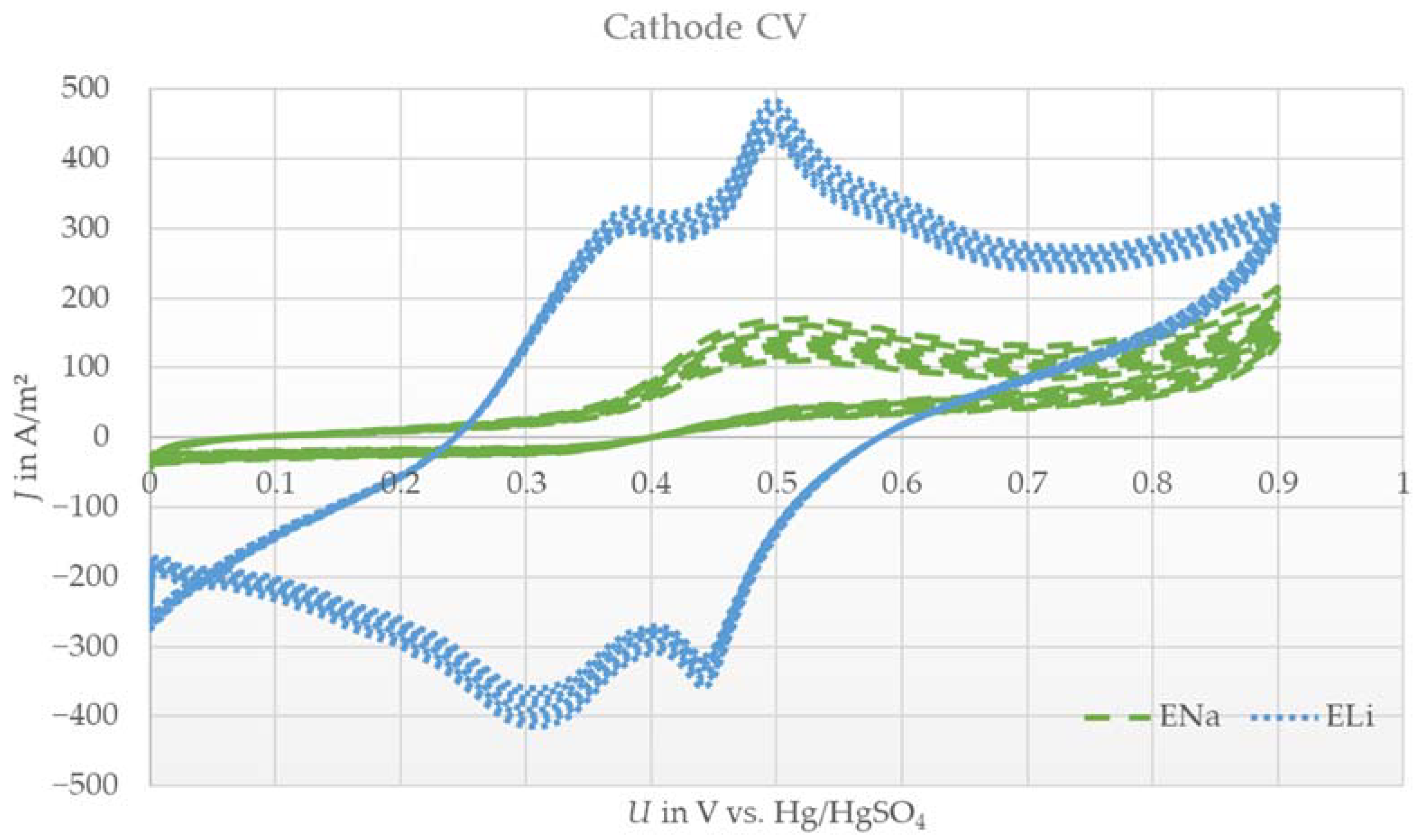
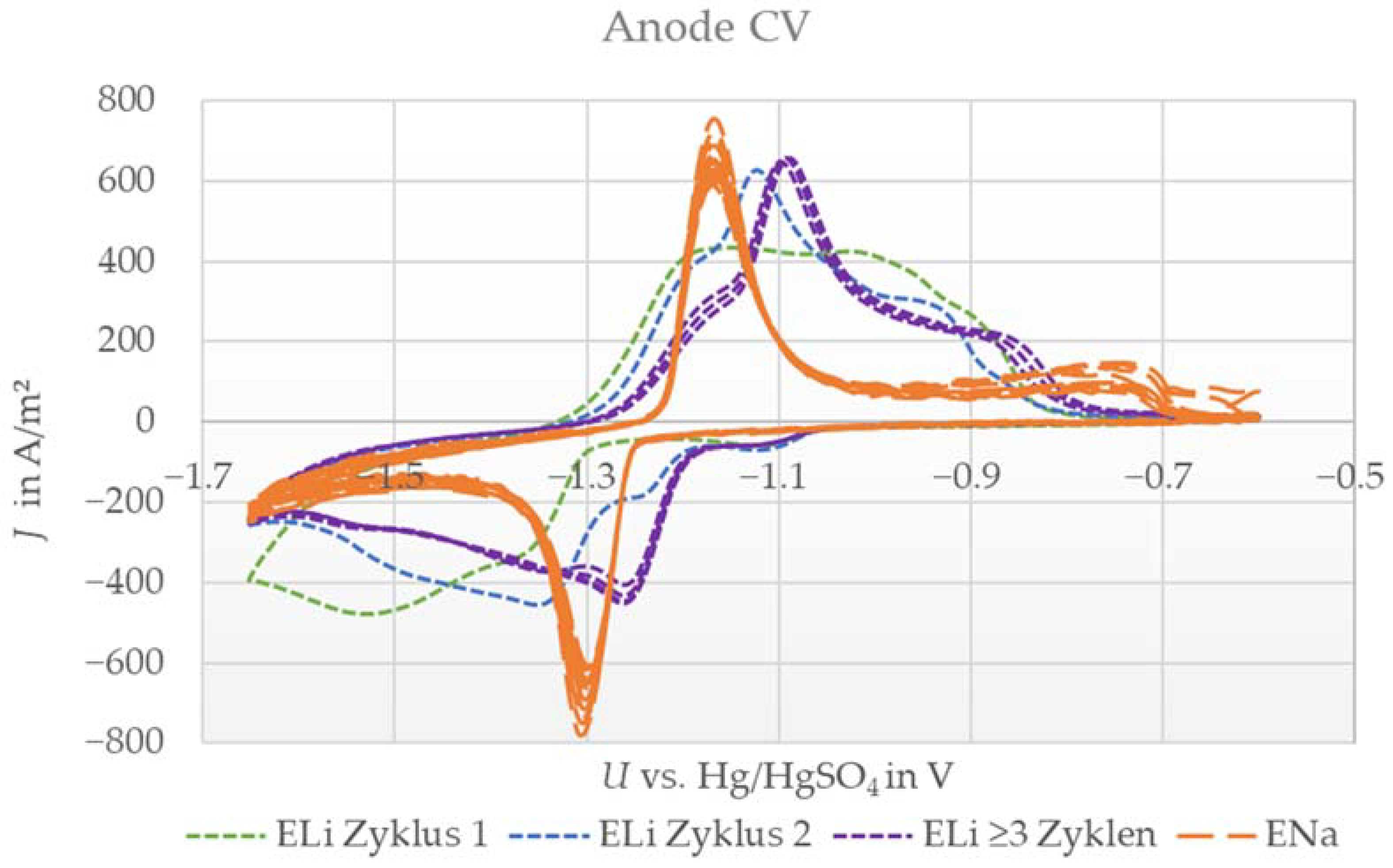
3.1. Cyclic Voltammetry

As a first step, we executed CV measurements to identify whether Na+ and/or Li+ can act as active ions for single electrodes. Therefore, cathodes and anodes were analyzed separately with electrolyte containing solely lithium sulfate or sodium sulfate. For the cathode, two peaks and a reversible reaction were expected to be seen for lithium electrolyte, comparable to measurements in [19,28]. According to [10,22], the cathode should also work with sodium electrolyte and was thus expected to show a similar curve shape.
Figure 1 shows the cyclic voltammograms of the cathode using electrolytes with dissolved lithium sulfate (ELi) and sodium sulfate (ENa). By employing lithium sulfate as the conductive salt, two oxidation and reduction peaks were observable, expressing a reversible two-stage reaction.
For the case of using sodium sulfate as the conductive salt (ENa), no intense peak was identified, even over 10 cycles. Only a weak and broad reduction peak was observed, yet an oxidation peak was missing completely.
The results with ELi were expected, due to the similar shape compared to results in the literature [19,28]. The reversible reaction indicates that lithium ions can be the active species for the cathode electrode. On the contrary, the results with ENa indicate an irreversible reaction. As described in [10], a slow exchange of lithium with sodium in the cathode material was expected in the case of lithium absence in the electrolyte. This indicates a similar curve shape to that shown in Figure 1 with ELi with small shifts in the peak intensity and voltage level of the peaks. Even when cycling for 10 cycles, no increase or change in shape occurred. More than that, a slight decrease in the little existing peak was observed after cycling. The cathode seemed to be electrochemically inactive under these conditions. The amount of lithium in the pristine LMO was too low to undergo a measurable reversible reaction in the measurement set up. This could be due to the small electrode size and thus the low amount of pristine lithium ions compared to the excess amount of electrolyte. The CV data led to the assumption that sodium ions are not possible active species for LMO cathodes under dual-ion battery conditions. Therefore, the given CV results reveal that lithium ions are active species for cathode electrodes.
For the anode, one reversible peak was expected in combination with electrolyte containing only sodium sulfate as well as that containing only lithium sulfate, as shown in [10,13,17,18,20,28,30]. Notably, the intercalation process is considered to be a two-phase reaction for both electrolyte types. The lithium (ELi) and sodium (ENa) systems are shown in Figure 2.
The measurement with ENa electrolyte showed one oxidation and reduction peak, indicating a reversible reaction, which is in excellent agreement with the literature [10,13,15,18,20]. In contrast, the measurement with ELi indicated a more complex behavior. Here, the signal was smeared out compared with that of the ENa system, and additionally, the shape changed over the first three cycles. From cycles one to three, the peaks became more pronounced and shifted to higher voltages by −1.1 V vs. Hg/HgSO4. After the third cycle, the system stabilized, and further sweeps showed almost identical behavior. Conclusively, in this case, we also observed a reversible reaction.
The changes in shape and peak position led us to assume that there is a side reaction in the first two cycles, such as the formation of another species, before a stable reaction takes place. Nevertheless, the anode showed reversible reactions with both ions in accordance with the literature and in contrast to the investigated LMO. Thus, both ions can be the dominant active species for anode electrodes in dual-ion batteries. However, after stabilization with ELi, the peak position differed by ≈80 mV to higher voltages (meaning less negative) compared to the ENa system. Consequently, lithium intercalation is slightly preferred in cases where both ions are available, indicating that a lithium-dominated reaction also occurs for anode electrodes.

3.2. Full Cell Measurement

To further validate the results found by CV, we performed full cell measurements with electrolytes containing different conductive salts. From previous findings, we expected that the full cell setup with electrolyte containing only sodium sulfate (ENa) would not really work due to the cathode behavior, whereas the lithium-based electrolyte (ELi) should perform at least similarly to standard electrolyte (EStd) containing both ions, as used in the “Saltwater Battery”. The results are shown in Figure 3.
At a rate of C/10, the ENa system reached 60% of the capacity compared to standard electrolyte containing both ions, while the ELi system reached 120%. At C/6, the trend and discrepancy between the systems were even more prominent: the ENa system was nearly inert, reaching only 0.1% of the original capacity, whereas the ELi system performed 90% better than the standard.
The sodium system @C/10 showed a relatively high capacity of 60%, which was not expected due to the CV results of the cathode with ENa showing no significant peak. On the contrary, the behavior at @C/6 was expected. The anode works well with sodium according to CV, so the cathodes presumably cause the poor performance of the full cell with ENa. The fact that the system performed quite well at C/10 leads to two possible explanations that are both based on the small current. On one hand, sodium ions with their larger ionic radius (116 pm for Na+ vs. 90 pm for Li+ [32]) might intercalate in the manganese oxide spinel when the discharge period is long enough (10 h at C-rate C/10). The intercalation of sodium should work at the same C-rate according to [10]. A possible reason why our CV results showed no interaction with sodium could be the shorter time used for one complete charge–discharge cycle during the voltage sweep due to the higher specific current (2.5 h compared to 20 h, respectively 160 mA/g vs. 6 mA/g). On the other hand, the lithium which is extracted from the cathode during charging may again reintercalate during discharge. This process might also be invisible in CV due to the lower specific current and/or the lower amount of electrolyte per electrode mass in the full cell (4000 mL/g vs. 75 mL/g). This results in both a longer charge–discharge cycle and shorter diffusion pathways in the full cell. Considering the first case, the results indicate that 60% of the original lithium content in LiMn2O4 can be replaced with sodium during a 10 h discharge period. If our second interpretation holds true, it shows that 60% of the lithium ions can be reintercalated within this 10 h window. Since there is no evidence for significant Na+ intercalation into the LMO structure in our XRD results (see below), we conclude that the second case is more plausible, yet further research is required to validate this finding.
The capacity reached with ELi compared to EStd shows the ability of both electrodes to work with lithium ions. The significantly higher capacity compared to the standard system substantiates the idea that lithium is the preferred species in both electrodes. This is in accordance with the shift in our CV measurements of the anode. Finally, the superior performance of ELi at a rate of C/6 compared to C/10 could have been caused by the sodium ions in the electrolyte hindering and/or slowing the electrode reaction.
The analyzed system works best with electrolyte containing only lithium sulfate as the conductive salt. The addition of sodium sulfate to electrolyte deteriorates the capacity retention of a working battery.

3.3. Ion Analysis of Electrolyte

To further investigate the role of sodium in our full cells, we performed an ion analysis of electrolyte. Here, two different aspects were of major importance. First, if the working principle described in the literature [5,8,9,10,12,14,15,16,17,18,19,20,21,22,23,24,25,26,27,28,29] is valid in this system, the charged battery (SoC 100%) should be composed of a sodium-saturated anode and an Li-depleted cathode. Thus, the Li+ content in electrolyte should be increased compared to fresh electrolyte, whereas the opposite should be the case for the Na+ content. In the discharged battery (SoC 0%), however, it would be the opposite: a higher sodium and a lower lithium content in electrolyte. If both electrodes only react with lithium, as concluded from the CV and full cell results, the lithium content in electrolyte should remain unchanged. The same holds true for the sodium content. Second, by comparing the ion content of electrolyte after the activation cycles with fresh electrolyte, we drew conclusions about the formation reactions. If there is no formation of an interphase, such as the solid electrolyte interphase (SEI) in standard LIB or other side reactions, the ion amount should remain similar before and after the activation cycles. If a formation reaction takes place, a change in the electrolyte concentration should be detectable. The results are shown in Table 3.
The contents of both ions were 18% higher after activation compared to those in fresh electrolyte, indicating a strong link between the ion reactions. Furthermore, this change clearly indicates a formation reaction and can be associated with the change in the anode CV curve in a lithium-containing electrolyte during the first two cycles (Figure 2). The activation step for the full cell, and thus the basis for the ion analysis, also comprises two full cycles. The irreversible capacity loss measured in the previously mentioned full cell measurements over activation cycles was approximately 20%, which is close to the changes in electrolyte concentrations. This indicates a strong link between the full cell activation losses in the first two cycles and the increase in the ion content in electrolyte, along with a decrease in the ion content in the electrodes. All three measurements led to the conclusion that formation is happening during cell activation. A formation mechanism for sodium titanium phosphate anodes in aqueous solution is presented in [26]. The authors identified the formation of titanium phosphates as well as titanium sulfates during activation. Additionally, they measured an increase in the sodium content in electrolyte due to this reaction, which is in accordance with our data. This hints also to a partial dissolution of the initial phase NaTi2(PO4)3.
Furthermore, the ion analysis revealed an increase in lithium ions in electrolyte after charging. This goes along with the literature [8,12,19,22,25,28], showing the expected deintercalation of lithium ions during charging and the associated release of lithium ions into the electrolyte. Interestingly, the sodium content also increased slightly during charging. This might be another hint of partial dissolution of the initial NaTi2(PO4)3 phase, which is the only viable source of additional sodium in the system. According to the working principle described in the literature [12,18,20,24], the sodium content in electrolyte should be reduced in the charged battery state. This trend is decoupled from the formation process, since it was virtually finished after two cycles according to the CV results (Figure 2) and, consequently, did not influence the ion content during cycling. The system seems to be quite stable, as the change in sodium content of 2% is small compared to the change in the lithium concentration of 12%. Thus, these findings cannot be described with a solely lithium-based (de)intercalation working principle on the anode and cathode sides, as expected from the CV and full cell results, or with a sodium-dominated (de)intercalation process on the anode side, as described in the literature [10,12,18]. We conclude that sodium is either inactive, as indicated by the full cell measurements and CV, or undergoes a reversible reaction during charging and discharging without affecting the actual electrolyte concentration. This contradicts the sodium-dominated working principle on the anode side assumed in the literature [10,12,18,20,24] and lets us assume that another reaction has to take place. However, during cycling, the sodium as well as the lithium content are equally increased on a molar basis compared to fresh electrolyte, indicating a strong link between sodium and lithium reactions.

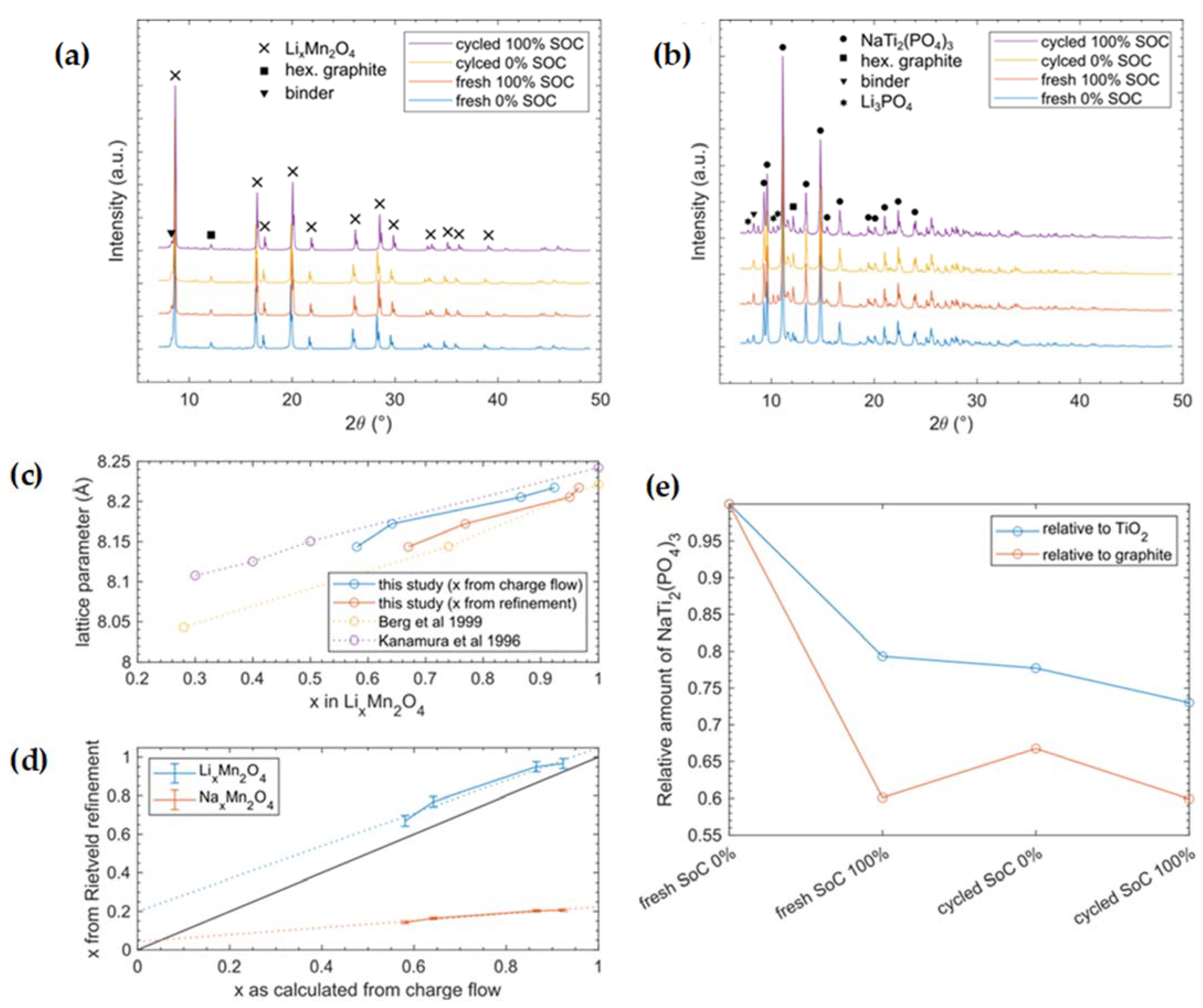
3.4. X-ray Diffraction

So far, our present results partially contradict the reported working principle of the “Saltwater Battery” in its hybrid form, in which Li+ is (de)intercalated on the cathode side and Na+ is (de)intercalated on the anode side. Consequently, we performed an XRD analysis to clarify which crystalline phases are present for different SoCs as well as different cycle numbers. For normal intercalation processes, we expected that the utilized spinel-type LMO would show a cubic phase with varying lattice parameters (e.g., [33,34]). Since lithium is a very light element with a low electron density, its (de)intercalation will not lead to significant intensity changes in the reflections. However, shifts of reflections by 2θ resulting from changes in lattice parameters should occur. Electrochemical delithiation of LixMn2O4 is known to involve only one single spinel phase and not a coexistence of two phases [35]. Alternatively, for the intercalation of sodium, we would expect significant intensity changes, while new phases might also form, as indicated by unassigned peaks in the diffraction pattern [36].
The intercalation process on the anode side was reported to be a two-phase process, where no transition compound Na1+xTi2(PO4)3 was detected. Hence, during intercalation, a new phase Na3Ti2(PO4)3 is formed, which would result in the appearance of new reflections in XRD and a coexistence of the two phases [37,38]. An intercalation of solely lithium or the formation of another phase would lead to peak shifts as well as additional or missing peaks. Another alternative reaction might be the partial intercalation of lithium and the formation of a mixed structure (Na1−xLix)3Ti2(PO4)3. Such mixed compounds would also result in changed lattice parameters and additional or markedly shifted reflections.
The XRD measurement data are shown in Figure 4, whereas the detailed refinement results, including all refined parameters, phases as well as the instrument parameters can be found in the Supplementary Materials.
XRD measurements of the cathode electrode showed expected reflections of the cubic spinel-type LixMn2O4 phase for both the discharged and charged states. The reflections shifted due to extension/contraction of the lattice during the insertion/extraction of lithium ions. Furthermore, we identified reflections from hexagonal graphite, which is part of the cathode mixture. Finally, we found three Li and/or Na containing sulfates (hydrated and nonhydrated) in tiny amounts. We assume that these salts precipitated from electrolyte that was not removed from the sample material before measurement. In summary, there were no prominent new phases that played major roles during cycling. The refined progress of the lattice parameters (see Figure 4c) is in perfect accordance with the literature, in which only Li+ was used for (de)intercalation [33]. Since the bigger Na+ ion requires more space in the structure, increased lattice expansion would be expected. Equation (4) gives the calculation for the number of electrons with respect to the x-value of lithium in the formula LixMn2O4 based on our measured charge flow. Furthermore, the Li occupancy obtained from Rietveld refinement of the structure fits well with electrochemical measurements assuming the (de)intercalation of 1 ion per electron (Figure 4d). From XRD, we obtained a transfer of ~0.85 Li+/e; the deviation from unity could have been caused by uncertainties, since only four data points were used to determine our linear fit. The underestimation of lithium transfer can be explained either by electron losses due to cell resistance and side reactions or by partial Na intercalation (<5%). On the other hand, when assuming pure NaxMn2O4 chemistry in the Rietveld refinement, the Na occupancy would explain the measured charge flow, only if merely 0.18 ions were (de)intercalated per electron, which is far from an expected behavior of such materials.
x L M O = 1 i Q c h a r g e i Q d i s c h a r g e i e · n t o t L i
Here, XLMO is the x value in LixMn2O4, Qcharge(i) and Qdischarge(i) are the measured capacities of the ith charge and discharge cycle (unit Coulomb), e is the elementary charge (unit Coulomb), and ntot(Li) is the total amount of Li atoms in the pristine LMO material of the cathode electrode.
The XRD measurements of the anode electrode are summarized in Table 4 and showed the NASICON-type phase NaTi2(PO4)3. Surprisingly, this phase showed no significant changes during charging or during cycling. While there were slight variations in lattice parameters a and c, we are not able to make a clear statement about its origin, yet we cannot rule out that it might originate from slight Li uptake by the material. However, as the literature indicates, reduced NASICONs A3Ti2(PO4)3 (A = Li/Na) tends to be sensitive to air or unstable vs. dissolved oxygen in aqueous solutions [40,41,42] undergoing a self-discharge reaction. This self-discharge could occur during sample contact with air during transportation or during the long lasting XRD measurements, which might explain why we did not see much change between the SoC 0% and SoC 100% anode samples in XRD. Consequently, we could not identify the active intercalation compound on the anode side. Nevertheless, we observed graphite as well as some sulfates in tiny amounts in the anode samples. Furthermore, we identified reflections of the anatase (TiO2) phase that originated from NASICON synthesis, as similarly reported in [10]. To our astonishment, the only indication of a chemical reaction was found in the charged state (SoC 100%) in form of a Li3PO4 phase, in both fresh cells as well as in cells that were cycled 100 times. This phase was missing in the discharged state and, therefore, seems to be formed via charging and remains stable in an oxygen atmosphere. The Li3PO4 phase could also be a decomposition product of mixed sodium–lithium–titanium–phosphate, which would decompose due to self-discharge on oxygen contact into Li3PO4. However, the resulting compositions of the anode in weight percents are summarized in Table 5. Since the only compound in the cell that contains phosphate is the anode active material, the precipitated Li3PO4 has to originate from here. A partial dissolution of NaTiPO is also described in [8,19], resulting in findings of Li3PO4 [8]. The Li3PO4 has non-negligible solubility in aqueous media, such as the used electrolyte in [43] with 450 mg/L; consequently, the XRD observed quantity of crystalline Li3PO4 was the amount above its saturation point. In addition, by using inactive compounds as the internal reference in our XRD measurements, we were able to derive the degree of dissolution of NaTiPO (Figure 4e). This result has to be interpreted with care, since graphite often shows a preferred orientation and, thus, is not ideal as an internal reference. On the other hand, for TiO2, we had to presume that it was inactive during electrochemical cycling, which is plausible, but we cannot completely rule out any electrochemical interference just by the experiments performed. However, both lines (in Figure 4e) show the same trend, and thus, we deduce that a measurable dissolution of NaTiPO took place.
In summary, our findings lead us to conclude that the lithium intercalation reaction in LMO takes place on the cathode side, while we identified the dissolution of NaTiPO during operation. Due to the self-discharge mechanism in the presence of oxygen, similar reflections occur in the charged and discharged states, hindering conclusions about the active ion intercalation mechanism for anodes. However, our results show that a partial dissolution of NaTi2(PO4)3 is a significant part of the cycling process. The dissolved (PO4)3− ions are the only source to form the precipitated Li3PO4, while the sodium and titanium ions remaining in the solution during charging are hidden from XRD in an amorphous state. According to [26], dissolved titanium ions can undergo a reaction, changing the oxidation state reversibly from 4+ to 3+ and, thus, might contribute slightly to the electron transfer during operation. However, during discharge, solid Li3PO4 on the anode side disappears again, indicating the removal of this salt from electrolyte. This could be due to lithium intercalation taking place on the cathode side. Additionally, a formation mechanism of Li3PO4 only based on the oxygen self-discharge could explain its appearance in the charged state. Nevertheless, the dissolution of NaTiPO in a lithium-containing environment as well as the assumed reversible formation of Li3PO4 can explain the peak shift during formation and the stabilized peaks found afterwards in CV. More than that, the irreversible capacity loss during two activation cycles is explained by the previously described formation phenomenon. Furthermore, the increased sodium in electrolyte after formation can be explained by the NaTiPO dissolution. The dissolution measured by XRD is ≈12–15 wt.%, which is close to the measured sodium increase of ≈18 wt.% in electrolyte. Three possibilities remain as the anode reaction mechanism: (1) the intercalation of sodium; (2) solely the intercalation of lithium; and (3) the intercalation of lithium leading to an ion mixture in NaTiPO. Even though the specific reacting ion species on the anode side remains unclear, the third option seems to be the most likely, and XRD measurements still revealed a formation process accompanied by NaTiPO dissolution.

4. Conclusions

This research focused on identifying the active species on the anode as well as the cathode side in a commercially available dual-ion battery system containing lithium and sodium on an aqueous basis. According to the results from previous literature, manganese oxide structures, as the active cathode material, as well as NASICON-type sodium titanium phosphate, as the active anode material, can intercalate both types of ions, depending on the ion availability in electrolyte [5,8,9,10,12,14,15,16,17,18,19,20,21,22,23,24,25,26,27,28,29].
The findings of this work support the assumption that the anode material can interact with lithium and sodium in a reversible reaction. In contrast to this, the CV measurements indicate that the activity of the spinel (lithium manganese oxide) is limited to lithium and does not intercalate sodium in a significant amount. The phase analysis of XRD patterns supports this conclusion and substantiates the described intercalation process on the cathode side. The active species on the cathode side was unequivocally identified as lithium. More than that, sodium seems to hinder the electrochemical process, as found in electrochemical full cell measurements.
The results regarding the anode contradicted expectations. A formation process based on the partial dissolution of sodium titanium phosphate during the battery activation cycles was revealed, which seems to lead to a reversible formation of Li3PO4 during charging. However, intercalation was not detectable in XRD on the anode side for Li+ or Na+ due to the dominant self-discharge reaction in the presence of oxygen during transportation. Although the XRD measurement did not help to identify the active ion on the anode side, the CV as well as the full cell results led to the conclusion that lithium is the dominant ion in the hybrid system, supporting the reaction described by Wang et al. [8]. To conclude, for the analyzed Li-Na dual-ion system, Li ions were identified as the preferred active ion for both electrodes.
Thus, these results indicate that the dual-ion “Saltwater Battery”, as available on the market, is only a single-ion aqueous lithium system or at least a battery type dominated by lithium. Therefore, the system and materials can be improved with a new focus on the lithium reaction. The sodium sulfate dissolved in electrolyte can be eliminated, saving a minor part of the electrolyte costs. However, more than that, it leads to superior performance of the battery, as shown in the full cell measurements. This behavior needs to be further investigated in full cell measurements as well as with a prompt gamma activation analysis and will open new pathways for improving the battery’s performance, such as the development of new electrode formulations regarding the composition and used materials for beneficial lithium (de)intercalation characteristics.

Supplementary Materials

The following supporting information can be downloaded at: https://www.mdpi.com/article/10.3390/en16114485/s1, Figure S1: Rietveld fits of the fresh cathode at 0% SoC. Figure S2: Rietveld fits of the fresh anode at 0% SoC. Figure S3: Rietveld fits of the fresh cathode at 100% SoC. Figure S4: Rietveld fits of the fresh anode at 100% SoC. Figure S5: Rietveld fits of the cycled cathode at 0% SoC. Figure S6: Rietveld fits of the cycled anode at 0% SoC. Figure S7: Rietveld fits of the cycled cathode at 100% SoC. Figure S8: Rietveld fits of the cycled anode at 100% SoC. Figure S9: SEM picture of sodium titanium phosphate. Figure S10: SEM picture of lithium manganese spinel. Table S1: Listed results of the refined parameters extracted from Rietveld refinement of the anode samples. Table S2: Parameters of the utilized instrument resolution function for Rietveld refinement. Table S3: Listed results of the refined parameters extracted from Rietveld refinement of the cathode samples.

Author Contributions

Conceptualization, J.S., K.-H.P., S.S. and M.A.D.; methodology, J.S., K.-H.P., L.G., S.S., R.G. and M.A.D.; validation, J.S., K.-H.P., L.G., R.G. and S.S.; formal analysis, J.S., L.G., R.G. and S.S.; investigation, J.S., L.G. and S.S.; resources, J.S. and L.G.; data curation, J.S. and L.G.; writing—original draft preparation, J.S., L.G. and S.S.; writing—review and editing, J.S., K.-H.P., L.G., S.S., R.G. and M.A.D.; visualization, J.S. and L.G.; supervision, J.S., K.-H.P., R.G. and M.A.D.; project administration, J.S.; funding acquisition, J.S., R.G. and K.-H.P. All authors have read and agreed to the published version of the manuscript.

Funding

This research was funded by BMWK, grant number 03EI3046F and BMBF (Federal Ministry of Education and Research, Germany) “ExZellTUM III”, project number 03XP0255.

Data Availability Statement

Data is unavailable due to privacy restrictions.

Acknowledgments

We thank the Physics Lab of the Heinz Maier-Leibnitz Zentrum for measuring time at the diffractometer and Alexander Book for adjustment of the instrument.

Conflicts of Interest

The authors declare no conflict of interest.

Appendix A

For XRD, a flat plate transmission geometry was used with a reflection/transmission spinner stage. Samples consisting of weighed amounts of anode material (373 mg) and cathode material (144 mg) were placed between two Kapton foils and measured on a rotating stage. This sample amount was calculated to result in less than ≈70% transmission of the primary beam to give a good signal/noise ratio in XRD. The sample was set up with a transmission geometry. The fixed beam irradiated the plate at a normal incidence. The sample plate was in the center of the goniometer with a radius of 240 mm. The detector scanned the goniometer circle at around 2θ. Mo radiation with a focusing mirror was applied to focus the beam onto the detector and serve as a filter, resulting in nearly pure Kα1/2 radiation (λ(Kα1) = 0.7093187 Å; λ(Kα2) = 0.7136090 Å). We used 1/4° Ta divergence and antiscatter slits on the incident beam to achieve a high resolution and low noise. Soller slits with 0.02 rad placed on the incident and diffracted beam sides further enhanced the resolution. The Malvern Panalytical GaliPIX3D detector was equipped with a transmission cap, reducing the background level caused by air scattering. We collected diffraction data in the range of 2θ = 7°–49°. The measurement procedure stepped through the range with a step size of 0.007° and step time of 130.26 s, giving a total duration of ≈30 min for a single scan. Eight scans were successively gathered and summed up for each sample, resulting in a total measurement time of ≈4 h/sample. To enhance the particle statistics, the sample stage was rotated at 0.25 Hz.
The diffraction patterns were analyzed with the software package GSAS-II v.5468 [44]. We applied the Rietveld method [45] using a combination of the following phases as initial settings (cif-files provided either by the Crystallographic Open Database (COD) or the Inorganic Crystal Structure Database (ICSD)):
  • LiMn2O4(LMO): COD #1514006
  • Graphite: ICSD #76767
  • LiNaSO4: COD #2106021
  • Li2SO4(H2O): COD #1008190
  • Na3Li(SO4)2(H20)6: COD #2243890
  • NaTi2(PO4)3 (NaTiPO): ICSD #19995
  • Li3PO4: ICSD #10257
  • TiO2 (Anatase): COD #9008214
  • Na2SO4: COD #9004092
The instrument resolution function was obtained by Rietveld refinement of powder data from a NIST-660c LaB6 sample using ~20 mg of LaB6 powder sandwiched between two Kapton foils measured in the same sample holder and with identical instrumental settings as described above. For consistency, we refined the same set of parameters for all anode and cathode samples, respectively. For the anode samples we refined
  • Six coefficients of the Chebyshev-1 background polynomial model;
  • Two separate background peaks at 2θ = 8.29° and 8.17° that originated from the binder;
  • Lattice parameters and phase fractions of all phases;
  • One isotropic microstrain parameter for each phase except for NaTiPO;
  • Three anisotropic microstrain parameters for NaTiPO using the generalized model;
  • One isotropic atomic displacement factor U for all atoms of the NaTiPO and Li3PO4 phases, respectively;
  • All possible atomic positions of the NaTiPO and Li3PO4 phases.
For the cathode samples we refined
  • Six coefficients of the Chebyshev-1 background polynomial model;
  • One separate background peak at 2θ = 8.29° that originated from the binder;
  • Lattice parameters and phase fractions of all phases;
  • One isotropic microstrain parameter for each phase except for LMO and Na3Li(SO4)2(H2O)6;
  • Two anisotropic microstrain parameters for LMO using the generalized model;
  • No broadening model was used for Na3Li(SO4)2(H2O)6 because its phase fraction was too low;
  • One isotropic atomic displacement factor U for all atoms of the LMO phase;
  • The x-position of the oxygen atom in the LMO phase;
  • The fraction of Li in the LMO phase was set to a value extracted from the summed transferred charge measured by the potentiostat. We assume that the same amount of Li+ was removed from LMO by assuming a transfer ratio of 1 Li+/e.
All isotropic size parameters were set to the maximum possible value of 10 µm, since the broadening did not improve the fit. All other isotropic atomic displacement factors were set to 0.01, because it lies in an acceptable range and could not be refined for these atoms due to the low intensity contribution of the respective phases. For LiNaSO4 and Na3Li(SO4)2(H2O)6, we set fixed anisotropic atomic displacement factors, as provided by the used cif-file.

References

  1. Zugschwert, C.; Dundálek, J.; Leyer, S.; Hadji-Minaglou, J.-R.; Kosek, J.; Pettinger, K.-H. The Effect of Input Parameter Variation on the Accuracy of a Vanadium Redox Flow Battery Simulation Model. Batteries 2021, 7, 7. [Google Scholar] [CrossRef]
  2. Oh, H.G.; Park, S.-K. Co-MOF Derived MoSe2@CoSe2/N-Doped Carbon Nanorods as High-Performance Anode Materials for Potassium Ion Batteries. Int. J. Energy Res. 2022, 46, 10677–10688. [Google Scholar] [CrossRef]
  3. Deng, Q.; Wang, M.; Liu, X.; Fan, H.; Zhang, Y.; Yang, H.Y. Ultrathin Cobalt Nickel Selenides (Co0.5Ni0.5Se2) Nanosheet Arrays Anchoring on Ti3C2 MXene for High-Performance Na+/K+ Batteries. J. Colloid Interface Sci. 2022, 626, 700–709. [Google Scholar] [CrossRef]
  4. Li, X.; Liang, H.; Qin, B.; Wang, M.; Zhang, Y.; Fan, H. Rational Design of Heterostructured Bimetallic Sulfides (CoS2/NC@VS4) with VS4 Nanodots Decorated on CoS2 Dodecahedron for High-Performance Sodium and Potassium Ion Batteries. J. Colloid Interface Sci. 2022, 625, 41–49. [Google Scholar] [CrossRef] [PubMed]
  5. Bin, D.; Wang, F.; Tamirat, A.G.; Suo, L.; Wang, Y.; Wang, C.; Xia, Y. Progress in Aqueous Rechargeable Sodium-Ion Batteries. Adv. Energy Mater. 2018, 8, 1703008. [Google Scholar] [CrossRef]
  6. Li, W.-H.; Wu, X.-L. Advanced Cathode Materials in Dual-Ion Batteries: Progress and Prospect. Electrochem. Sci. Adv. 2022, 2, e2100127. [Google Scholar] [CrossRef]
  7. Wang, X.-T.; Yang, Y.; Guo, J.-Z.; Gu, Z.-Y.; Ang, E.H.; Sun, Z.-H.; Li, W.-H.; Liang, H.-J.; Wu, X.-L. An Advanced Cathode Composite for Co-Utilization of Cations and Anions in Lithium Batteries. J. Mater. Sci. Technol. 2022, 102, 72–79. [Google Scholar] [CrossRef]
  8. Wang, H.; Wang, R.; Song, Z.; Zhang, H.; Zhang, H.; Wang, Y.; Li, X. A Novel Aqueous Li+ (or Na+)/Br Hybrid-Ion Battery with Super High Areal Capacity and Energy Density. J. Mater. Chem. A 2019, 7, 13050–13059. [Google Scholar] [CrossRef]
  9. Zhang, Z.; Hu, X.; Zhou, Y.; Wang, S.; Yao, L.; Pan, H.; Su, C.-Y.; Chen, F.; Hou, X. Aqueous Rechargeable Dual-Ion Battery Based on Fluoride Ion and Sodium Ion Electrochemistry. J. Mater. Chem. A 2018, 6, 8244–8250. [Google Scholar] [CrossRef]
  10. Whitacre, J.F.; Shanbhag, S.; Mohamed, A.; Polonsky, A.; Carlisle, K.; Gulakowski, J.; Wu, W.; Smith, C.; Cooney, L.; Blackwood, D.; et al. A Polyionic, Large-Format Energy Storage Device Using an Aqueous Electrolyte and Thick-Format Composite NaTi 2 (PO 4 ) 3 /Activated Carbon Negative Electrodes. Energy Technol. 2015, 3, 20–31. [Google Scholar] [CrossRef] [Green Version]
  11. Kalapsazova, M.; Rasheev, H.; Zhecheva, E.; Tadjer, A.; Stoyanova, R. Insights into the Function of Electrode and Electrolyte Materials in a Hybrid Lithium–Sodium Ion Cell. J. Phys. Chem. C 2019, 123, 11508–11521. [Google Scholar] [CrossRef]
  12. Kim, H.; Hong, J.; Park, K.-Y.; Kim, H.; Kim, S.-W.; Kang, K. Aqueous Rechargeable Li and Na Ion Batteries. Chem. Rev. 2014, 114, 11788–11827. [Google Scholar] [CrossRef] [PubMed]
  13. Mohamed, A.I.; Whitacre, J.F. Capacity Fade of NaTi2(PO4)3 in Aqueous Electrolyte Solutions: Relating PH Increases to Long Term Stability. Electrochim. Acta 2017, 235, 730–739. [Google Scholar] [CrossRef]
  14. Whitacre, J.F.; Wiley, T.; Shanbhag, S.; Wenzhuo, Y.; Mohamed, A.; Chun, S.E.; Weber, E.; Blackwood, D.; Lynch-Bell, E.; Gulakowski, J.; et al. An Aqueous Electrolyte, Sodium Ion Functional, Large Format Energy Storage Device for Stationary Applications. J. Power Sources 2012, 213, 255–264. [Google Scholar] [CrossRef]
  15. Wu, W.; Yan, J.; Wise, A.; Rutt, A.; Whitacre, J.F. Using Intimate Carbon to Enhance the Performance of NaTi2(PO4)3 Anode Materials: Carbon Nanotubes vs Graphite. J. Electrochem. Soc. 2014, 161, 561–567. [Google Scholar] [CrossRef]
  16. Wang, H.; Zhang, H.; Cheng, Y.; Feng, K.; Li, X.; Zhang, H. Rational Design and Synthesis of LiTi 2 (PO 4 ) 3−x F x Anode Materials for High-Performance Aqueous Lithium Ion Batteries. J. Mater. Chem. A 2017, 5, 593–599. [Google Scholar] [CrossRef]
  17. Wu, W.; Mohamed, A.; Whitacre, J.F. Microwave Synthesized NaTi2(PO4)3 as an Aqueous Sodium-Ion Negative Electrode. J. Electrochem. Soc. 2013, 160, 497–504. [Google Scholar] [CrossRef]
  18. Hou, Z.; Li, X.; Liang, J.; Zhu, Y.; Qian, Y. An Aqueous Rechargeable Sodium Ion Battery Based on a NaMnO2–NaTi2(PO4)3 Hybrid System for Stationary Energy Storage. J. Mater. Chem. A 2015, 3, 1400–1404. [Google Scholar] [CrossRef]
  19. Sun, D.; Jin, G.; Tang, Y.; Zhang, R.; Xue, X.; Huang, X.; Chu, H.; Wang, H. NaTi2 (PO4)3 Nanoparticles Embedded in Carbon Matrix as Long-Lived Anode for Aqueous Lithium Ion Battery. J. Electrochem. Soc. 2016, 163, A1388–A1393. [Google Scholar] [CrossRef]
  20. Park, S.I.; Gocheva, I.; Okada, S.; Yamaki, J.-I. Electrochemical Properties of NaTi2(PO4)3 Anode for Rechargeable Aqueous Sodium-Ion Batteries. J. Electrochem. Soc. 2011, 158, 1067–1070. [Google Scholar] [CrossRef]
  21. Whitacre, J.F.; Tevar, A.; Sharma, S. Na4Mn9O18 as a Positive Electrode Material for an Aqueous Electrolyte Sodium-Ion Energy Storage Device. Electrochem. Commun. 2010, 12, 463–466. [Google Scholar] [CrossRef]
  22. Wang, Y.; Chen, L.; Wang, Y.; Xia, Y. Cycling Stability of Spinel LiMn2O4 with Different Particle Sizes in Aqueous Electrolyte. Electrochim. Acta 2015, 173, 178–183. [Google Scholar] [CrossRef]
  23. Zhu, Z.; Peelaers, H.; Van de Walle, C.G. Hydrogen-Induced Degradation of NaMnO2. Chem. Mater. 2019, 31, 5224–5228. [Google Scholar] [CrossRef]
  24. Li, Z.; Young, D.; Xiang, K.; Carter, W.C.; Chiang, Y.-M. Towards High Power High Energy Aqueous Sodium-Ion Batteries: The NaTi2 (PO4)3 /Na0.44MnO2 System. Adv. Energy Mater. 2013, 3, 290–294. [Google Scholar] [CrossRef]
  25. He, X.; Wang, J.; Qiu, B.; Paillard, E.; Ma, C.; Cao, X.; Liu, H.; Stan, M.C.; Liu, H.; Gallash, T.; et al. Durable High-Rate Capability Na0.44MnO2 Cathode Material for Sodium-Ion Batteries. Nano Energy 2016, 27, 602–610. [Google Scholar] [CrossRef] [Green Version]
  26. Zhan, X.; Shirpour, M. Evolution of Solid/Aqueous Interface in Aqueous Sodium-Ion Batteries. Chem. Commun. 2017, 53, 204–207. [Google Scholar] [CrossRef]
  27. Sauvage, F.; Laffont, L.; Tarascon, J.-M.; Baudrin, E. Study of the Insertion/Deinsertion Mechanism of Sodium into Na0.44MnO2. Inorg. Chem. 2007, 46, 3289–3294. [Google Scholar] [CrossRef]
  28. Luo, J.-Y.; Xia, Y.-Y. Aqueous Lithium-Ion Battery LiTi2(PO4)3/LiMn2O4 with High Power and Energy Densities as Well as Superior Cycling Stability**. Adv. Funct. Mater. 2007, 17, 3877–3884. [Google Scholar] [CrossRef]
  29. Tang, W.; Hou, Y.; Wang, F.; Liu, L.; Wu, Y.; Zhu, K. LiMn 2 O 4 Nanotube as Cathode Material of Second-Level Charge Capability for Aqueous Rechargeable Batteries. Nano Lett. 2013, 13, 2036–2040. [Google Scholar] [CrossRef]
  30. Chen, L.; Liu, J.; Guo, Z.; Wang, Y.; Wang, C.; Xia, Y. Electrochemical Profile of LiTi2(PO4)3 and NaTi2(PO4)3 in Lithium, Sodium or Mixed Ion Aqueous Solutions. J. Electrochem. Soc. 2016, 163, A904. [Google Scholar] [CrossRef]
  31. DIN EN ISO/IEC 17025:2018-03; Allgemeine Anforderungen an Die Kompetenz von Prüf- Und Kalibrierlaboratorien. Deutsche Beuth Verlag GmbH: Berlin, Germany, 2018.
  32. Binnewies, M.; Finze, M.; Jäckel, M.; Schmidt, P.; Willner, H.; Rayner-Canham, G. Allgemeine und Anorganische Chemie; Springer: Berlin/Heidelberg, Germany, 2016; ISBN 978-3-662-45066-6. [Google Scholar]
  33. Luo, F.; Wei, C.; Zhang, C.; Gao, H.; Niu, J.; Ma, W.; Peng, Z.; Bai, Y.; Zhang, Z. Operando X-Ray Diffraction Analysis of the Degradation Mechanisms of a Spinel LiMn2O4 Cathode in Different Voltage Windows. J. Energy Chem. 2020, 44, 138–146. [Google Scholar] [CrossRef] [Green Version]
  34. Marchini, F.; Rubi, D.; del Pozo, M.; Williams, F.J.; Calvo, E.J. Surface Chemistry and Lithium-Ion Exchange in LiMn 2 O 4 for the Electrochemical Selective Extraction of LiCl from Natural Salt Lake Brines. J. Phys. Chem. C 2016, 120, 15875–15883. [Google Scholar] [CrossRef]
  35. Berg, H. Neutron Diffraction Study of Electrochemically Delithiated LiMn2O4 Spinel. Solid State Ion. 1999, 126, 227–234. [Google Scholar] [CrossRef]
  36. Yabuuchi, N.; Yano, M.; Kuze, S.; Komaba, S. Electrochemical Behavior and Structural Change of Spinel-Type Li[LixMn2−x]O4 (X = 0 and 0.2) in Sodium Cells. Electrochim. Acta 2012, 82, 296–301. [Google Scholar] [CrossRef]
  37. Yang, J.; Wang, H.; Hu, P.; Qi, J.; Guo, L.; Wang, L. A High-Rate and Ultralong-Life Sodium-Ion Battery Based on NaTi2(PO4)3 Nanocubes with Synergistic Coating of Carbon and Rutile TiO2. Small 2015, 11, 3744–3749. [Google Scholar] [CrossRef] [PubMed]
  38. Kabbour, H.; Coillot, D.; Colmont, M.; Masquelier, C.; Mentré, O. α-Na3M2 (PO4)3(M = Ti, Fe): Absolute Cationic Ordering in NASICON-Type Phases. J. Am. Chem. Soc. 2011, 133, 11900–11903. [Google Scholar] [CrossRef]
  39. Kanamura, K.; Naito, H.; Yao, T.; Takehara, Z. Structural Change of the LiMn2O4 Spinel Structure Induced by Extraction of Lithium. J. Mater. Chem. 1996, 6, 33. [Google Scholar] [CrossRef]
  40. Jazouli, A.E.; Nadiri, A.; Dance, J.M.; Delmas, C.; Flem, L. Relationships between Structure and Magnetic Properties of Titanium (III) NASICON-Type Phosphates. J. Phys. Chem. Solids 1988, 7, 779–783. [Google Scholar] [CrossRef]
  41. Luo, J.-Y.; Cui, W.-J.; He, P.; Xia, Y.-Y. Raising the Cycling Stability of Aqueous Lithium-Ion Batteries by Eliminating Oxygen in the Electrolyte. Nat. Chem. 2010, 2, 760–765. [Google Scholar] [CrossRef]
  42. Chen, L.; Cao, L.; Ji, X.; Hou, S.; Li, Q.; Chen, J.; Yang, C.; Eidson, N.; Wang, C. Enabling Safe Aqueous Lithium Ion Open Batteries by Suppressing Oxygen Reduction Reaction. Nat. Commun. 2020, 11, 2638. [Google Scholar] [CrossRef]
  43. Song, Y.-J. Recovery of Lithium as Li3PO4 from Waste Water in a LIB Recycling Process. Korean J. Met. Mater. 2018, 56, 755–762. [Google Scholar] [CrossRef] [Green Version]
  44. Toby, B.H.; Von Dreele, R.B. It GSAS-II: The Genesis of a Modern Open-Source All Purpose Crystallography Software Package. J. Appl. Crystallogr. 2013, 46, 544–549. [Google Scholar] [CrossRef]
  45. Rietveld, H.M. A Profile Refinement Method for Nuclear and Magnetic Structures. J. Appl. Crystallogr. 1969, 2, 65–71. [Google Scholar] [CrossRef]
Figure 1. Exemplary cyclic voltammograms (10 cycles) of the spinel lithium manganese oxide cathode with aqueous lithium sulfate electrolyte (ELi) or sodium sulfate electrolyte (ENa) versus a platinum counter electrode and Hg/HgSO4 reference at a scan rate of 0.1 mV/s.
Energies 16 04485 g001
Figure 2. Cyclic voltammograms (10 cycles) of the sodium titanium phosphate anode with aqueous lithium sulfate electrolyte (ELi) or sodium sulfate electrolyte (ENa) against the platinum counter electrode and Hg/HgSO4 reference at a scan rate of 0.1 mV/s.
Energies 16 04485 g002
Figure 3. Capacity of the full cell measurement at C/10 (5th overall cycle, 3rd with C/10) and C/6 (23rd overall cycle, 1st with C/6) with solely lithium sulfate (ELi) with respect to sodium sulfate (ENa) electrolyte normalized to the capacity of standard full cell and electrolyte containing both ions (EStd).
Energies 16 04485 g003
Figure 4. XRD patterns of cathode (a) as well as anode (b) samples for fresh cells directly after formation and cycled ones after 100 cycles. (c) shows the experimental lattice parameter as a function of x in LixMn2O4. Thereby, x can be extracted from the charge flow measured by the potentiostat, assuming the (de)intercalation of 1 Li+/e or Rietveld refinement. Here, our data are compared with the literature [35,39] where only Li+ was intercalated. (d) Comparison of x in Lix(Nax)Mn2O4 with the charge flow extracted with a potentiostat and Rietveld refinement. The black line with a slope of 1 shows the idealized case in which 1 ion is (de)intercalated per measured e, while in reality, additional electrons are needed to account for losses, cell resistance, side reactions, etc. The dotted lines are fitted to the data. Fit equations: (blue dotted line) LixMn2O4 -> f(x) = 0.8487x + 0.1999; (orange dotted line) NaxMn2O4 -> f(x) = 0.1815x + 0.0429). (e) Evolution of the NaTi2(PO4)3 amount in the measured anode samples. Here, the weight fraction of NaTi2(PO4)3 is divided by the weight fractions of TiO2 and graphite, respectively. The result is then plotted relative to the “fresh Soc 0%” sample.
Energies 16 04485 g004
Table 1. Electrode compositions of the commercially available “Saltwater Battery” according to weight percentage [10].
ComponentFunctionWeight Percentage
in Anode/%
Weight Percentage
in Cathode/%
NaTiPOAnode intercalation material700
LMOCathode intercalation material080
Carbon blackElectrical conduction72
GraphiteElectrical conduction310
PolytetrafluoroethyleneBinder material58
Activated CarbonAnode additive for cycle stability150
Table 2. Materials used for electrode preparation according to the weight percentages stated in Table 1.
TypeElectrodeProduct NameSupplier
LMOCathodeHLM-Y01Eachem, Hunan, China
NaTiPOAnodeCustomized synthesis according to [10]
Activated carbonAnodePAK C-1000CCarboTech, Essen, Germany
Carbon blackAnode and cathodeSuper PImerys, Willebroek, Belgium
GraphiteAnode and cathodeKS6Imerys, Bodio, Switzerland
PolytetrafluoroethyleneAnodeAlgoflon L203Solvay, Bollate, Italy
PolytetrafluoroethyleneCathodeDyneon TF 2021Z3M, Burgkirchen, Germany
Table 3. Results of the electrolyte ion analysis regarding sodium and lithium contents with ion exchange chromatography referring to the full cells described in Section 3.2.
Fresh Electrolyte before FillingSample 0% SoCSample 100% SoC
Lithium content in g/L11.113.114.7
Sodium content in g/L58.469.270.4
Table 4. Results of the cathode XRD measurement with refined sample compositions in weight percentages for the four different test samples. The numbers in brackets show the ±1σ standard deviation.
SampleLixMn2O4 in wt.%Graphite in wt.%LiNaSO4 in wt.%Li2SO4(H2O) in wt.%Na3Li(SO4)2(H2O)6 in wt.%
Fresh SoC 0%86.9(2)7.8(2)1.95(9)4.5(8)2.9(2)
Fresh SoC 100%87.4(2)8.6(2)1.3(1)2.7(2)0.000
Cycled SoC 0%86.8(2)9.5(2)3.2(1)0.0000.5(1)
Cycled SoC 100%87.4(2)8.4(2)1.4(2)2.8(2)0.000
Table 5. Results of the anode XRD measurement with the refined sample compositions in weight percentages for the four different test samples. The numbers in brackets show the ±1σ standard deviation.
SampleNaTi2(PO4)3 in wt.%Graphite in wt.%Na3Li(SO4)2(H2O)6 in wt.%Li3PO4 in wt.%TiO2 in wt.%Na2SO4
in wt.%
Fresh SoC 0%86.4(2)6.5(2)4.4(2)0.0002.7(1)0.000
Fresh SoC 100%76.5(3)9.5(2)0.00011.0(3)3.0(1)0.000
Cycled SoC 0%86.8(2)9.7(2)0.0000.0003.5(1)0.000
Cycled SoC 100%73.5(2)9.2(2)0.0006.8(2)3.1(1)7.4(1)
Disclaimer/Publisher’s Note: The statements, opinions and data contained in all publications are solely those of the individual author(s) and contributor(s) and not of MDPI and/or the editor(s). MDPI and/or the editor(s) disclaim responsibility for any injury to people or property resulting from any ideas, methods, instructions or products referred to in the content.

