Article

Numerical and Experimental Investigation of the Decoupling Combustion Characteristics of a Burner with Flame Stabilizer

State Environmental Protection Key Laboratory of Efficient Utilization Technology of Coal Waste Resources, Engineering Research Center of Ministry of Education for Resource Efficiency Enhancing and Carbon Emission Reduction in Yellow River Basin, Institute of Resource and Environment Engineering, Shanxi University, Taiyuan 030006, China
*
Author to whom correspondence should be addressed.
Energies 2023, 16(11), 4474; https://doi.org/10.3390/en16114474
Submission received: 3 May 2023 / Revised: 27 May 2023 / Accepted: 29 May 2023 / Published: 1 June 2023

Abstract

:
In order to integrate renewable electricity into the power grid, it is crucial for coal-fired power plant boilers to operate stably across a wide load range. Achieving steady combustion with low nitrogen oxide (NOx) emissions poses a significant challenge for boilers burning low-volatile coal in coal-fired power plants. This study focuses on developing a decoupling combustion technology for low-volatile coal-fired boilers operating at low loads. A three-dimensional numerical simulation is employed to analyze and optimize the geometrical parameters of a burner applied in a real 300 MW pulverized coal fired boiler. Detailed analysis of the burner’s decoupling combustion characteristics, including stable combustion ability and NOx reduction principles, is conducted. The results indicate that this burner showed three stages of coal/air separation, and the flame holder facilitates the stepwise spontaneous ignition and combustion of low-volatile coal. By extending the time between coal pyrolysis and carbon combustion, the burner enhances decoupling combustion and achieves low nitrogen oxide emissions. Based on optimization, a flat partition plate without inclination demonstrates excellent performance in terms of velocity vector field distribution, coal air flow rich/lean separation, combustion, and nitrogen oxide generation. Compared with the initial structural design, the average nitrogen oxide concentration at the outlet is reduced by 59%.

1. Introduction

In an effort to mitigate the greenhouse effect, China has been actively working towards reducing carbon emissions in industrial production. Renewable energy sources play a significant role in carbon emission reduction and addressing climate change. However, fluctuation is the inherent characteristic of renewable electricity power, posing challenges for the power grid. As a result, coal-fired power plant boilers need to be adjustable and operate stably under both low and high load conditions. Low-volatile coal constitutes a significant proportion of coal production in China, and it is extensively utilized in power plants, meeting approximately 30% of the current electricity demands [1,2]. However, Kurose et al. [3,4,5,6] found that it is challenging to maintain a stable, high-efficiency combustion and low nitrogen oxide (NOx) emissions at the same time with low-volatile coal, especially under a low load. Down-fired combustion is widely applied for low-volatile coal consumption due to its high-temperature level and prolonged residence time of coal, enabling the use of coal with low volatility and poor reactivity [7]. However, practical operation of low-volatile coal-fired boilers still faces challenges such as high carbon content in fly ash and poor flame stabilization at low loads without oil support [8,9]. Additionally, despite the utilization of air-staging combustion, high temperatures lead to increased NOx emissions, reaching levels of approximately 1100−1800 mg/m3 (O2 at 6%) [10]. Nonetheless, with fluctuating electricity consumption and the growing need to support renewable energy generation, boilers need to operate under low load conditions frequently. Therefore, further advancements in low-volatile coal combustion technology are necessary.
To significantly reduce the NOx emissions from low-volatile coal combustion, researchers have focused on the burner design, optimizing air/fuel ratio, and introducing over-fire air [11]. The main principle of low-NOx combustion technology involves lowering the combustion temperature and postponing the fuel and oxygen’s mixing, thus creating a reductive atmosphere [12]. Thus, an appropriate low-NOx combustion condition is adverse to the combustion. It is still a challenge to reduce NOx emissions during the combustion process without decreasing the combustion efficiency at the same time, especially for low-volatile coal [12,13].
The burner, as a key component of pulverized coal combustion systems, plays a crucial role in the flow field within the furnace and the stable combustion of coal. Stable combustion burners can be broadly classified into two types: (1) those that modify the flow characteristics of the primary air through the use of bluff bodies to induce an adverse flow, such as a bluff body burner or slotted bluff body burners [14]; and (2) those that generate a central reflux area through swirl, such as swirl pulverized coal burners [15]. In large-scale four-wall tangentially-fired boilers, horizontal rich and lean burners are preferred over the swirl burners [16,17]. Slotted bluff-body burners have been shown to allow larger particles to enter the reflux zone directly, extending their residence time in the reflux zone. The hot reverse airflow in the reflux zone results in high temperature radiation and leads to quick releasing of coal volatiles. However, burners designed for high-quality coal combustion often fail to meet expectations for rapid load change response, flame stability, NOx control ability, and no-slagging propensity when burning low-volatile coal [18]. Shi et al. invented a slit bluff-body burner for low-volatile coal combustion, providing easier ignition and improved flame stabilization [19]. Additionally, Wei et al. investigated three kinds of low-volatile pulverized coal combustion in tangentially fired furnaces using new fuel rich/lean burners. The results showed that the coal concentration ratio between the fuel-rich and fuel-lean flows has important influences on temperature distributions and char burnout rate [20]. However, there is limited research on low-volatile burners that simultaneously consider stable combustion and NOx emissions. Therefore, the development of a new low-NOx burner capable of further reducing NOx emissions and enhancing combustion stability for low-volatile coal is crucial.
The decoupling combustion method has been proven effective in synchronously reducing NOx emissions and maintaining high coal burnout rates by separating coal pyrolysis and coal char burning, while guiding the pyrolysis gas flow through the combusting char bed [21]. In the decoupling combustion, the coal is first subjected to lean-oxygen combustion in an anoxic environment, so that the possibility of volatile nitrogen being oxidized to NO is significantly reduced. In addition, the heat generated at the same time causes coal pyrolysis. During the pyrolysis of coal, reducing gases, tar, and char are produced, and the tar is further thermally decomposed into heavy CnHm. The components of CO, H2, NH3, HCN and CmHn have strong reducibility to NOx. This kind of reducing gas and CnHm gas in tar first flow through the char layer and then enter the main combustion zone with sufficient air and could be burned out. Homogeneous and heterogeneous NOx reduction reactions occur in the char layer [22,23]. Based on the decoupling combustion mechanism, a decoupling combustion low-NOx burner (DLNB) (CN202452487U) was developed and investigated through experiment and cold mode numerical simulation in a previous report [24]. However, after applying this DLNB in a 300 MW boiler at a power plant in Taiyuan China, high-temperature corrosion issues emerged. To explore a more comprehensive understanding of the DLNB and improve its structure to address these problems, this paper analyzed its stable combustion mechanism and low-NOx combustion mechanism based on combustion numerical simulations. The DLNB is compared with a conventional horizontal fuel-rich/fuel-lean low-NOx burner (denoted as LNB) and its internal structure was optimized. Based on the simulation analysis, this paper provides a discussion on the stable combustion and low-NOx mechanism of the DLNB.

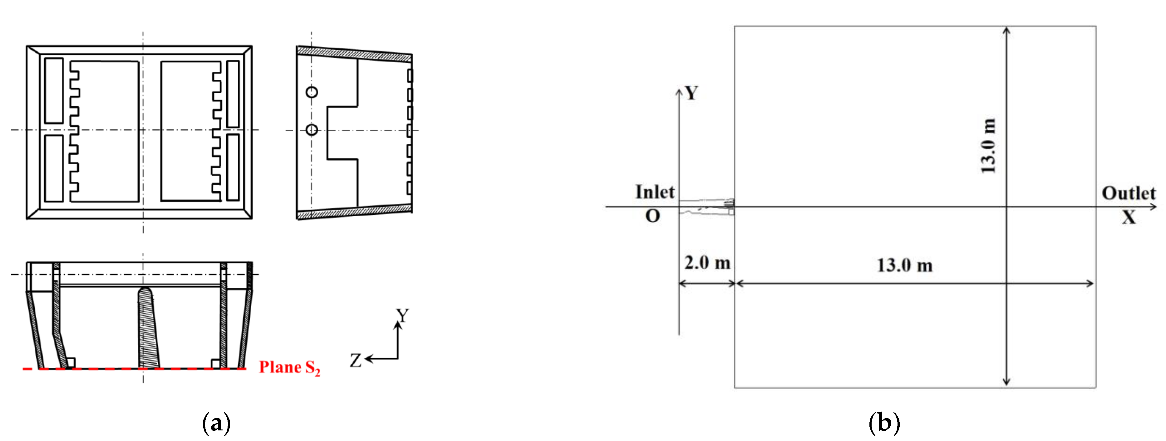
2. Burner Specifications

Achieving stable and low-NOx decoupling combustion requires addressing two key points. Firstly, improving the coal particle concentration in the primary air strengthens the coal pyrolysis process and thickens the volatile gases around the coal, ensuring that the volatile concentration reaches the ignition-limiting concentration.
This enables the transfer of low-volatile pulverized coal ignition from heterogeneous to homogeneous, reducing the ignition heat. Secondly, it is critical to maintain a long jet flow of char particles, which supports a reaction bed for NOx heterogeneous reduction by char. Additionally, a jet shear zone needs to be formed on the jet side to induce strong disturbance, reducing particle speed, prolonging particle residence time in high-temperature zones, and enhancing coal combustion reaction. Consequently, the concentrator and flame holder are crucial components in a low-NOx burner.
Figure 1 illustrates the schematic diagram of the DLNB. A collision block placed at the fuel-conveying path inlet separates the coal air flow into fuel-rich and fuel-lean streams (Figure 1b). The coal particles rebound multiple times due to the baffle plate and finally concentrate over the central partition plate, forming the fuel-rich side. The coal-rich flow passes through the stair-stepping flame holder, further concentrating on the fuel-rich side due to the obstruction provided by the flame holders (Figure 1a). Eventually, when ejected through the flame holder, the coal particle concentration in the fuel-rich flow reaches its maximum. This ultra-rich stream could promote a fuel-rich ignition, extending the flame penetration distance, increasing the coal particle residence time, and facilitating steady sequential combustion. It also delays the mixing of coal air flow and secondary air, strengthening the air-staged conditions and enlarging the reducing zone to ensure adequate coal pyrolysis, thereby inhibiting NOx formation.

3. Numerical Modeling

3.1. Domain and Mesh

The simulation calculation was based on the physical model of a cold experimental model. The cold experiment facility consists of a burner model (1.99 m in length, 0.6 m in width, and 0.49 m in height) for a 300 MW capability utility boiler, and a cube test chamber (3.5 m in diameter and 3.5 m in height), as shown in Figure 2. A regular hexahedron representing a fictitious furnace chamber was included in the geometry to investigate the jet flow of the burner (Figure 1c). The flow domain area was spatially discretized using a hexahedral mesh generated by the cutting cell method. The mesh was partially refined to accommodate the complex structure of the collision blocks and flame holder inside the burner. A grid independence test was performed based on the average flow velocity and the average particle density on the burner outlet cross-section, and a grid with a total number of 454,047 cells was selected. The meshed domain is shown in Figure 3.

3.2. Numerical Models

A three-dimensional two-phase flow model was employed for the numerical simulation using the commercial computational fluid dynamics (CFD) software product ANSYS FLUENT. The most fundamental method for solving turbulent problems is to solve the three-dimensional Navier–Stokes equations:
Mass conservation equation:
ρ t + ρ u i ¯ x j = 0
Momentum conservation equation:
ρ u i ¯ t + x j ( ρ u i u j ¯ ) = x j [ μ u i ¯ x j ρ u i u j ¯ ] p x i + ρ g i
Energy conservation equation:
ρ c p T ¯ t + x j ( ρ c p u j T ¯ ) = x j [ λ T ¯ x j ρ c p u j T ¯ ] + S f + S R
Conservation equation of components:
( ρ c s ) t + d i v ( ρ u c s ) = d i v ( D s g r a d ( ρ c s ) ) + S s
Among them, u i ¯ and u i are the average velocity and pulsation velocity in the three coordinate directions. T ¯ is the average temperature; gi is the gravitational acceleration component in the i direction. μ and λ are the dynamic viscosity coefficient and thermal conductivity coefficient caused by molecular thermal motion, respectively. Cs is the volume concentration of the s component, Ds is the diffusion coefficient of the component, and Ss is the mass of the component produced by a chemical reaction per unit volume of time within the system.
Compared with the Standard k-ε model, the Realizable k-ε model adds a new calculation formula for turbulent viscosity. Adding a Richardson number to the source term of the equation for correction can better reflect the characteristics of swirl flow, flow separation, strong adverse pressure gradient boundary layer flow, and secondary flow. Therefore, this paper uses the Realizable k-ε turbulence model to simulate the gas phase turbulent flow. Euler and Lagrange methods are mainly used to describe the two-phase flow. Since the flow of pulverized coal is close to the sparse suspension flow and the volume fraction of particle phase is less than 10%, the Lagrange particle trajectory model in the discrete phase model can be used to simulate the flow of particles. This method is the most widely used model in turbulent flow and combustion simulation.
Various sub-models describe the combustion process including the gas phase turbulent flow and combustion, the pulverized coal and air mixture gas-solid two-phase turbulent flow, the radiation, the release of volatiles, the char burning and burnout, and the NOx formation. The models utilized in this study are shown in Table 1.
The two-competing-rates model describes the release of volatiles in terms of two parallel and competing first-order reactions [25]. The weighting of the two kinetic rates is determined using Equation (1).
m v ( t ) 1 f w , 0 m p , 0 m a = 0 t ( α 1 R 1 + α 2 R 2 ) e x p 0 t ( R 1 + R 2 ) d t d t
where mv(t) is the volatile yield up to time t, fw,0 is the mass fraction of evaporating material, mp,0 is the initial particle mass at injection, ma is the ash content in the particles, and α1 and α2 are the two reactions’ yield factors separately. The yield factor represents de-volatilization at low temperature. It was recommended to be set to the fraction of volatiles determined by proximate analysis. In this study, considering the low volatile fraction (12.49% dry based) of the meager coal used as fuel, the first yield factor was set to 0.1. The second yield parameter represents the de-volatilization at high temperature; therefore, the value 1.0 was utilized for the second reaction(ANSYS., 2013).
The mixture-fraction probability density function (PDF) model was employed to simplify the combustion process by treating it as a mixture process. Instead of solving transport equations for each component, this model solves one or two transport equations for conserved quantities. The concentration of a single component is determined based on the predicted distribution of the mixed fraction.
In solving the conserved quantity, the probability density function p(f) is used to consider the interaction between turbulence and chemistry, and the concentration, density and temperature fields of each component are functions of the mixture-fraction f. The mixture-fraction f is defined as:
f = Z k Z k , o Z k , F Z k , o
where Zk represents the mass fraction of element K, and the angles F and O represent the values of fuel and oxidant, respectively. For a certain reactant i, the corresponding average concentration value can be obtained by the integral:
Y i = 0 1 Y i ( f ) p ( f ) d f
where Yi(f) represent the relationship between the concentration of reactant i and the instantaneous value of the mixture-fraction f. By determining the time average concentration of the reactants and the stoichiometric value of the mixture-fraction, the time average concentration of each product can be obtained by mass balance calculations.
This model was chosen as it adequately accounts for the coupling between turbulence and chemical reaction, while allowing for the prediction of the formation or decomposition of intermediates.
The prompt NOx formation was neglected, considering its low proportion in the pulverized furnace and only fuel NOx and thermal NOx were taken into account. It was assumed that fuel N was distributed between the char and volatiles. The char N directly converted to NO, while the volatile N converted to intermediates HCN and NH3 (HCN/NH3 = 9:1). Furthermore, a β-type PDF model of temperature pulsation was used to simulate the turbulence’s effects on NOx generation.
The reduction of NO by hydrocarbon fuels primarily involves intricate reactions between CH radicals and NO, which results in the suppressing of the HCN oxidation; thus, the NO formed from the fuel nitrogen is transferred from HCN to N2. The most important reactions of NO reduction by CnHm were considered to be:
NO + CH2 → HCN + OH
NO + CH → HCN + O
NO + C → CN + O
In this study, the Partial Equilibrium Approach was adapted for the NOx destruction in the fuel-rich zone by re-burning. Methane was defined as the re-burning fuel according to the C/H ratio of the meager coal.
The simulation utilized a finite volume pressure-based solver with implicit linearization, and the SIMPLE algorithm was used for pressure-velocity coupling.

3.3. Simulated Cases and Boundary Conditions

The DLNB was designed based on a horizontal burner used in a 300 MW lean coal-fired furnace at a thermal power plant in Shanxi province. Therefore, the boundary conditions in this study were set based on the rated conditions of the objective boiler. Details are shown below.

3.3.1. Comparison between DLNB and LNB

To verify the high-efficiency combustion and low-NOx characteristics of the DLNB, combustion numerical simulation of the DLNB and the LNB employed in the 300 MW lean coal-fired boiler were conducted, respectively. The structure of the LNB is shown in Figure 4.
The primary air velocity and temperature were set at 24.99 m/s and 220 °C. The velocity of the boundary wind was 35 m/s. The coal particle velocity and temperature were the same as that of the primary air. Based on the actual fuel consumption, the mass flow rate of these was 2.91 kg/s. According to the particle size distribution tests of the coal fired in the objective boilers, the coal particle size distribution follows the Rosin–Rammler distribution. The minimum diameter was 1 × 10⁻⁶ m, the maximum diameter was 0.0001 m, and the mean diameter was 7.6 × 10⁻⁵ m. The spread parameter was 9 and the number of diameters was 5. The outlet pressure was set as the atmospheric pressure. No-slip state and specular reflection conditions were applied on the surfaces of walls.
The results of the proximate analysis of coal samples are shown in Table 2. The Coal Calculator model was utilized to set up coal simulations. The Coal Calculator sets the corresponding volatiles for the Species and Pollutant models associated with coal combustion. For the fuel NOx model, the volatile N mass fraction was set to 0.024, and the char N mass fraction was set to 0.012.

3.3.2. DLNB Structure Optimization

Initially, the central partition plate of the DLNB was inclined by 10° towards the lean side to increase the coal concentration on fuel-rich side. However, previous studies demonstrated that the pulverized coal dense phase of DLNB flowed towards the lean side [24], weakening the separation characteristic. Therefore, optimization of the inclination angle of the central partition plate was necessary. Three different structures were studied in this research, and their parameters are listed in Table 3.

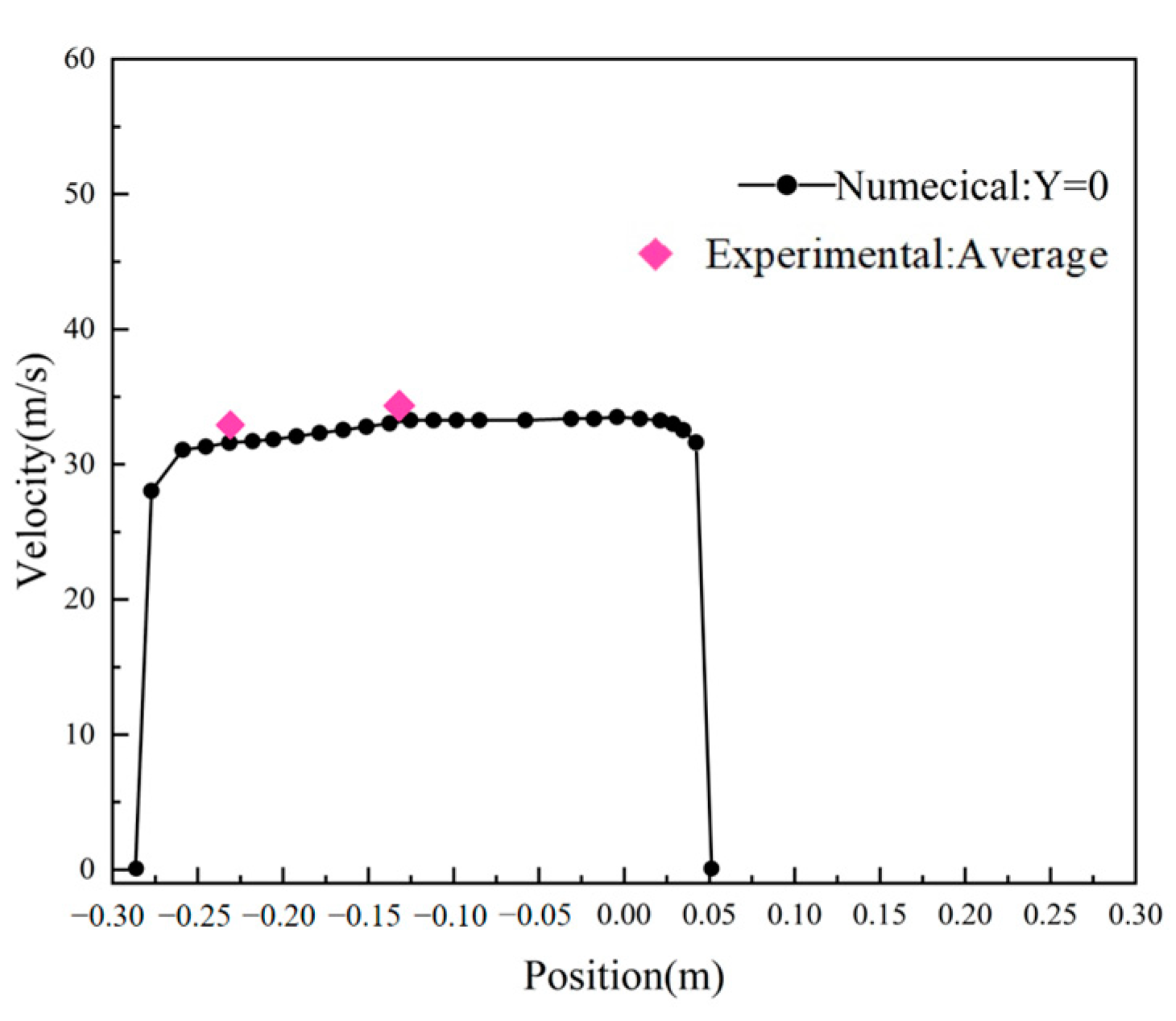
3.4. Model Validation

As discussed in our previous paper, the cold flow characteristic predicted by the models were validated by comparing with data obtained from cold experiments conducted on a full-scale model of an industrial burner [24]. The feeding rate of the cold experiment facility feeder can be controlled at ±5% of the design value. The velocity of primary air at the nozzle inlet was 25 m/s, and the temperature of the primary air and coal mixture was 20 °C. Velocity magnitude of two specified points B1 and B2 as marked in Figure 1a was investigated to explore their aerodynamic characteristics. Raw experimental data from 10 runs was collected by a testo 416-vane anemometer (accuracy: ±0.2 m/s + 1.5% of measured value) for each experimental point and their average values were used.
The actual velocity at the points of y = 0, z = −0.0125 and y = 0, z = −0.25 as marked in Figure 1a,b were measured, aiming to compare with the calculation results. Figure 5 depicts that the velocity distribution along the z-axis agrees well with the experimental results. However, for combustion characteristics, this is hard to validate by a full-scale experiment. Nevertheless, by comparing the data from different geometry with the same numerical model, the advantages and disadvantages of the burner structure could be qualitatively analyzed. Therefore, the model is deemed suitable for revealing the decoupling characteristic of this burner.

3.5. Separation Characteristics Analysis Method

The separation characteristics of the horizontal rich/lean burner can be quantitative analyzed using the following parameters:
Rich/lean stream quantity ratio: Rq = Qn/Qd
Rich/lean stream concentration ratio: Rc = Cn/Cd
Concentrating ratio: Rn = Cn/Co
Rich/lean stream velocity ratio:Rv = Vn/Vd
where Qn represents the rich side lean coal particle mass flow rate, m3/s, Qd represents lean stream pulverized coal mass flow rate, m3/s, Cn is the rich side coal particle concentration, kg/(kg·air), Cd represents the lean side coal particle concentration, kg/(kg·air), and Co represents the coal particle concentration at the concentrator entrance, kg/(kg·air).
When Rq is close to 1, it indicates a similar mass flow rate between the rich and lean sides, indicating a balance jet flow. Higher values of Rc and Rn are desirable, but there is a threshold beyond which combustion efficiency is adversely affected.

4. Results and Discussion

4.1. Comparison between DLNB and LNB

This section presents a comparative analysis of the separation and combustion characteristics of DLNB and LNB, aiming to assess the performance of DLNB.

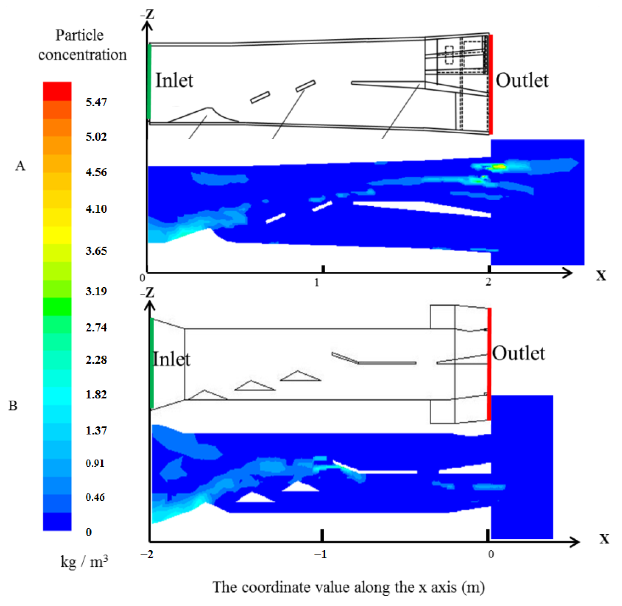
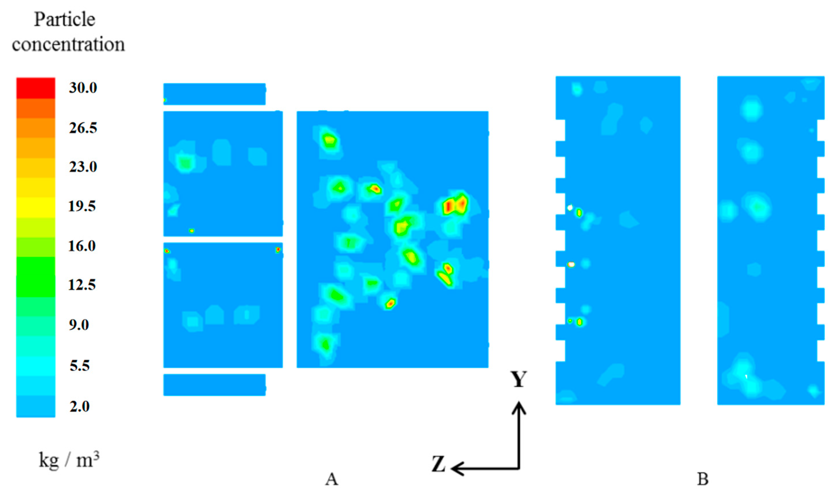
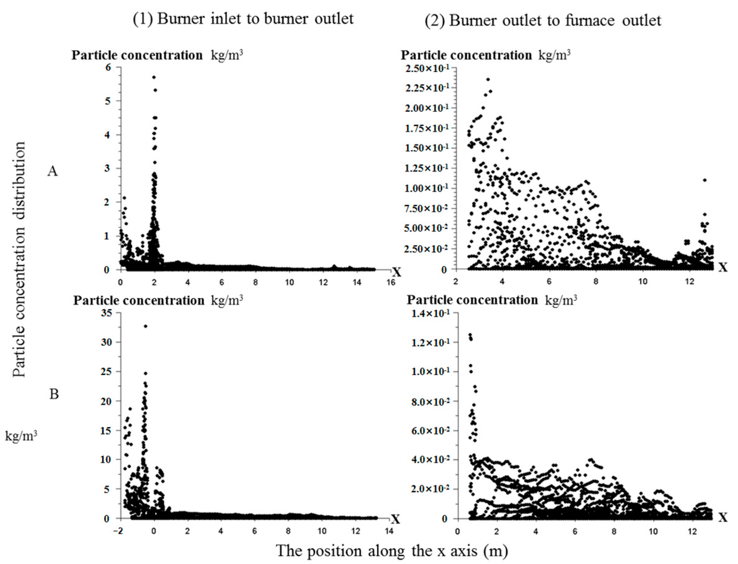
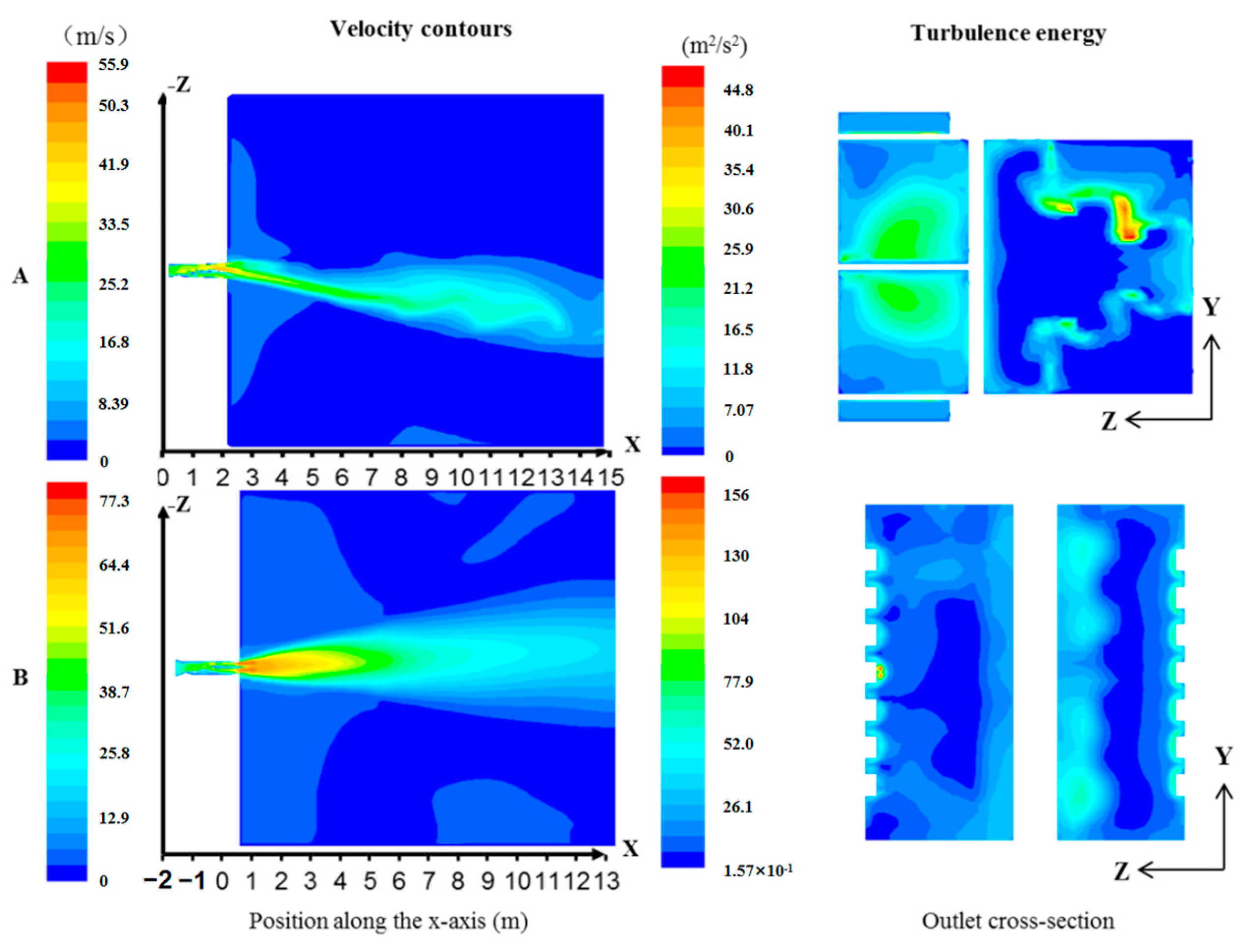
4.1.1. Separation Characteristics Comparison

The separation efficiency of the rich/lean burner relies on the arrangement of collision blocks, baffle plate, and the central partition plate. Figure 6 demonstrates that DLNB effectively concentrates the majority of the pulverized coal on the coal-rich side, indicating a well-designed internal structure. In contrast, LNB exhibits poor separation, as a significant amount of coal particles enters the lean side due to inadequate separation between the third block and the separation barrier. Table 4 shows superior separation parameters Rc and Rn for DLNB, which have values of 16.30 and 0.20, respectively, outperforming LNB. However, DLNB has a relatively large Rq, indicating the need for further optimization.
Figure 7 shows the particle concentration distribution contour on the outlet vertical cross-section (Figure 1 and Figure 4) of the DLNB and LNB. In both burners, after the separation by collision blocks and the central partition plate, most coal particles rebound to one side of the central partition, resulting in the division of pulverized coal-air flow divided into a thick rich-side flow and a weak lean-side flow, namely, the rich-side flow and lean-side flow. However, the two show very different particle distribution characteristics, and DLNB shows a better rich and lean separation effect. The difference in particle concentration between the two sides of LNB outlet is not much, and the highest concentration is almost 0.1 times of DLNB. Meanwhile, the particle concentration on the rich-side of DLNB outlet is much higher than that on the lean-side, and forms a gradient distribution of particle concentration on the rich side. In the DLNB, as the separated flow enters the stair-stepping flame holder, further concentration occurs. Due to the diversion of the flame holder, the air is deflected towards the ample space near the central partition plate, while the solid phase flows through the middle of the up and down holders due to inertia. This results in a three-level ladder-shaped concentration distribution: super-dense, rich, and lean. This super-dense coal-air flow facilitates quick ignition and stable combustion [26,27].
Figure 8 shows the distribution of the coal particle concentration of each line on the central horizontal plane for the two burner types. The scatter points represent concentration of pulverized coal particles along the x-axis. Higher concentrations of scattered points in the high-value zone indicate greater particle concentration at the corresponding positions. The figure shows that the DLNB exhibits a maximum concentration of 5.75 kg/s, while the LNB only reaches 2.5 kg/m3. Generally, the DLNB maintains higher coal particles concentration on the central horizontal plane compared to the LNB. The coal particle jet of the DLNB maintains a consistently high coal concentration (with a maximum concentration exceeding 0.11 kg/m3) up to 8.0 m outside the nozzle, forming a long bundle. In contrast, the LNB’s maximum concentration drops below 0.04 kg/m3, just 1.0 m from the nozzle outlet. This characteristic could enhance the reduction of volatile-N and char-N due to the pulverized char bundle, similar to the char layer in the decoupling combustion grate furnace [28].

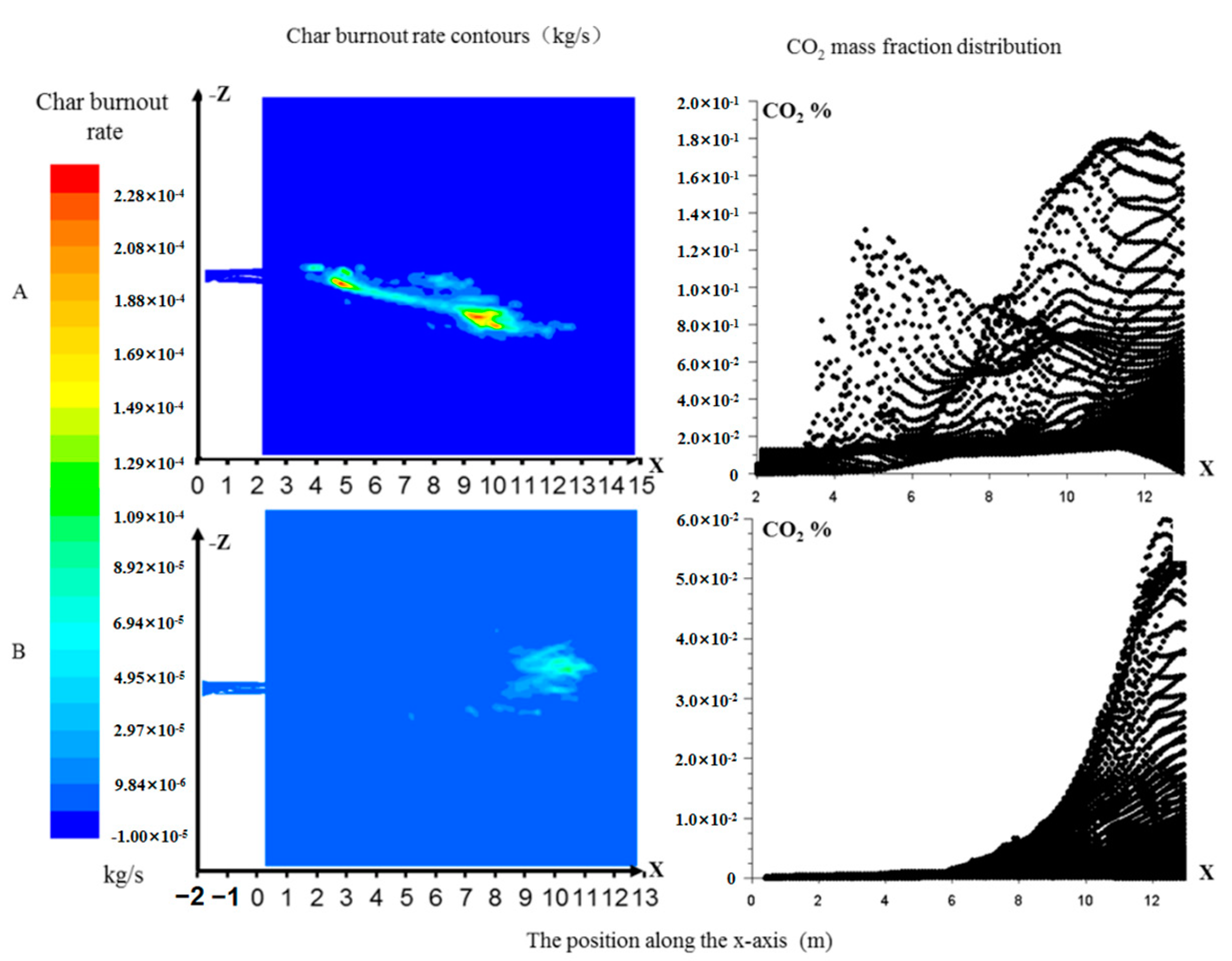
4.1.2. Combustion Characteristics Comparison

Figure 9 showcases the ignition process of DLNB, where ignition initiates 1.5 m from the nozzle and gradually spreads to the lean side at approximately 7.0 m. These findings prove advanced coal ignition in DLNB, facilitated by improved coal particle concentration. The presence of a flame holder in DLNB divides the coal-air flow into three streams, maintaining a long, stable pulverized coal bundle and minimizing coal particles dispersion. Consequently, the rich flow side ignites first, sequentially igniting the coal particles as a stable source of heat until the fuel-lean side begins to burn. Therefore, it leads to a ladder-shaped spontaneous steady combustion state and ensures stable combustion ability. In contrast, LNB experiences delayed release of volatiles 4.0 m from the nozzle. The temperature distribution shows that ignition happens 6.0 m from the nozzle, with the maximum temperature in the furnace approximately 500 °C lower than that in DLNB.
Figure 10 shows the char combustion rate of DLNB reached 6 kg/s within 2 m from the nozzle, whereas the LNB only reaches 2 kg/s at a distance of 8 m. DLNB achieves a maximum char combustion rate of 2.38 kg/s, compared to only 9.9 kg/s for LNB. The CO2 concentration of the LNB gradually increases starting from 6 m outside the nozzle, remaining significantly lower than that of DLNB. The conclusion could be drawn that DLNB demonstrates superior coal ignition and burnout rates.
This analysis highlights an essential role of the flame holder in achieving second-time concentration, leading to the progressive ignition of the pulverized coal. Moreover, the flame holder increased the perimeter length of the unit cross-sectional area of the super-dense coal flow, creating a strong backflow space with intense turbulence (Figure 11). This enhances the contact area between the coal airflow and the refluxed hot flue gas, promoting fast pyrolysis and stable combustion. While the flame holder in LNB also enhances the turbulent kinetic energy of the airflow(Figure 11B), its poor separation efficiency, ineffective blocks and partition plate, and inability to concentrate coal particles hinder fire-resistance coal ignition and steady combustion.
Due to the incomplete combustion in LNB under this condition, a comparison of NOx generation between the two burners is not possible. However, the following section discusses the NOx emission characteristic of DLNB.

4.2. DLNB Structure Optimization

In order to solve the jet-skewing problem of the initial design, the original design (case 1) was compared to the partition plate tilted at 0° (case 2) and tilted at 3° to the rich side (case 3).

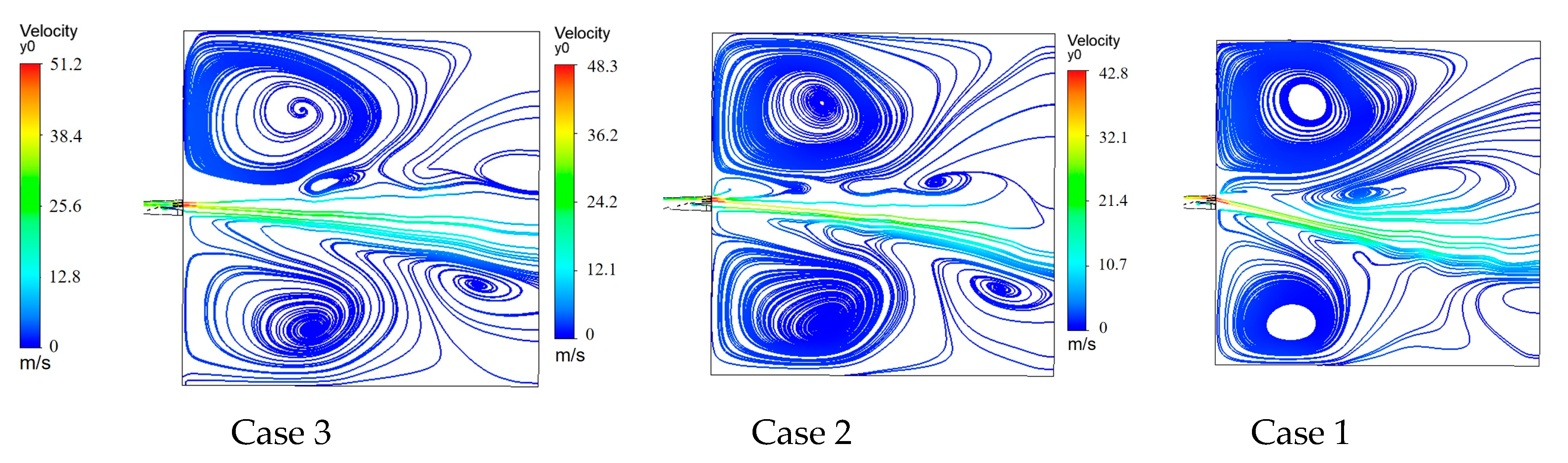
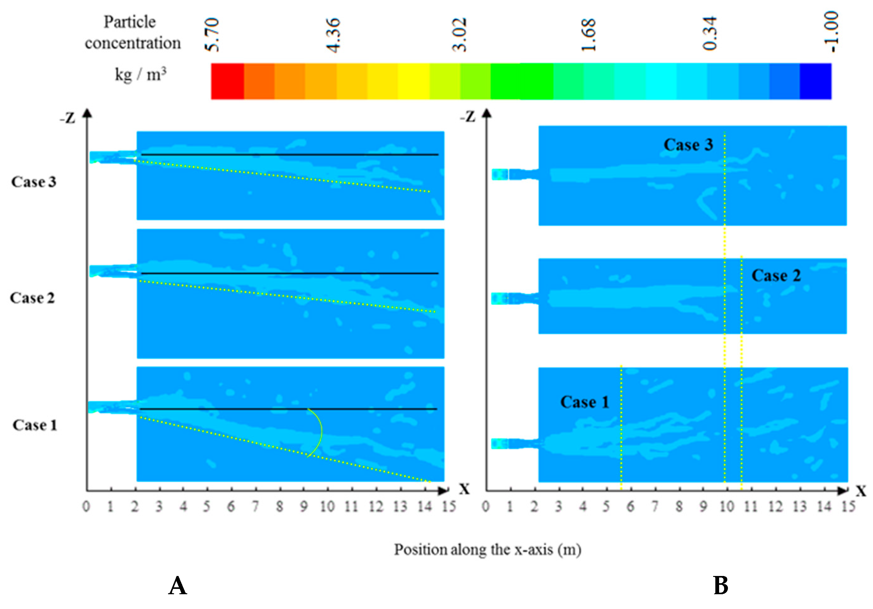
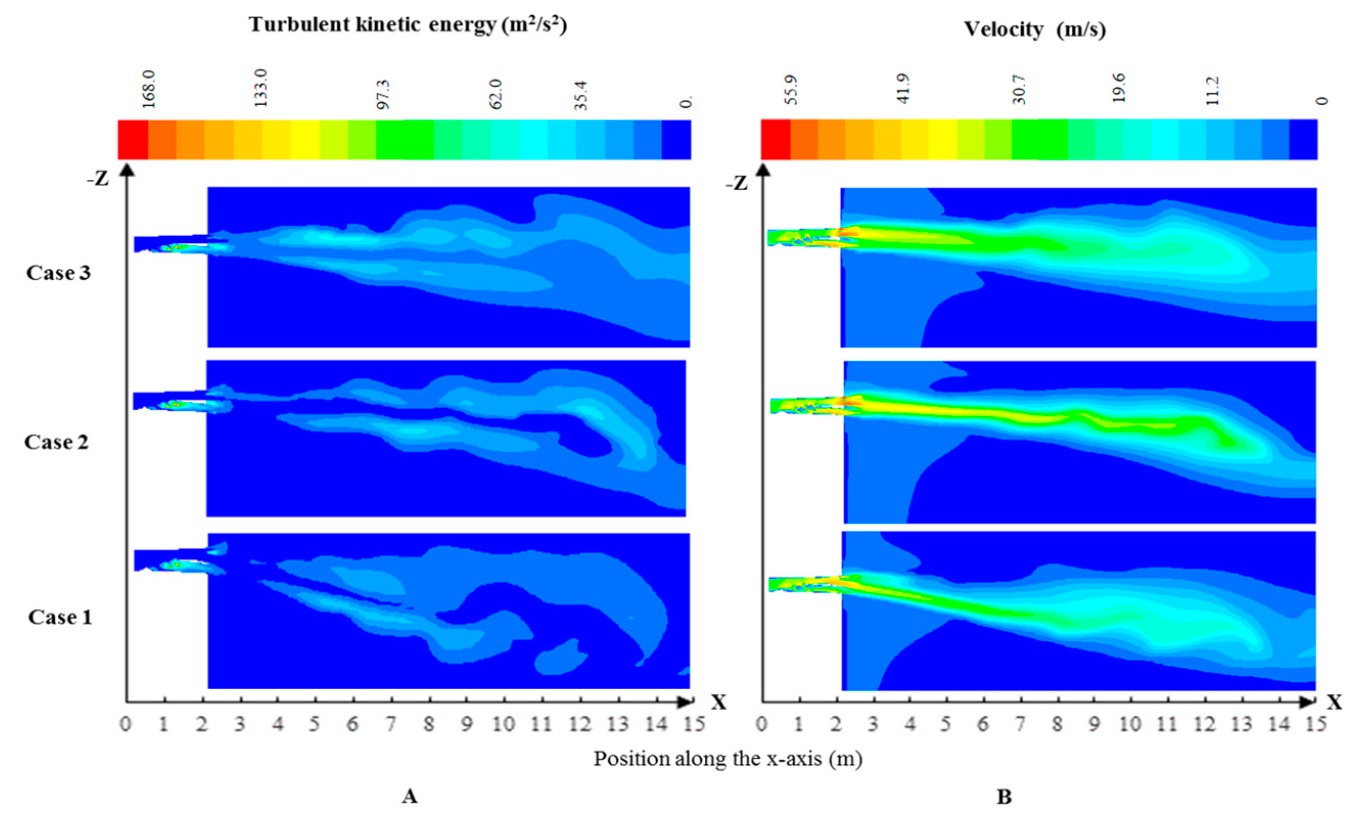
4.2.1. Flow-Field and Separation Characteristics

The coal air flow rich/lean separation characteristics for the three cases with different baffle angles are shown in Table 5. The analysis shows that a significant amount of pulverized coal particles gathers in the limited cross-section of the flame holder. Case 2 demonstrates superior separation with an Rc value of 22.94 and a Cn value of 1.43 kg/(kg·air) (Equivalent ratio = 2.10) on the rich side. Meanwhile, Cases 1 and 3 exhibit Rc values of 16.28 and 15.42, respectively, significantly lower than Case 2. Since a higher Rc value indicates better separation characteristic, Case 2 proves to be an effective separation structure.
Figure 12 shows the coal particle concentration contours for the central horizontal cross-section (X and Z plane). In Case 1, coal particles flow towards the coal-lean side, accompanied by short and divergent coal-air streams due to the inclination of the partition plate’s baffle towards the coal-lean side. As a result, Case 1 exhibits relatively comparatively large Rq and Rv. However, Rq of Case 2 is 0.85, closer to 1 than the other two cases, and a smaller Rv value compared to Case 1. Consequently, Case 2 experiences less deviation in coal-air flow between the two sides, thus resulting in a long and highly concentrated coal and air jet.
Figure 13 and Figure 14 provide insights into turbulent kinetic energy and velocity distribution, revealing the extensive jet range of Case 2, with the speed of 30 m/s remaining unattenuated up to 11 m from the nozzle. The turbulent kinetic energy inside the coal bundle is relatively low, while the turbulence outside is significantly higher. This indicates that the coal airflow in Case 2 remains rigid and less prone to deflection. In Figure 12A Case 3, the coal-air jet is straighter compared to the other two cases, with the least deviation in velocity between the two sides (Rv smaller than Case 2). However, Case 3 exhibits stronger turbulence in the overall jet area. This can be attributed to the narrowness of the rich side, leading to increased burner pressure drop from 598.85 Pa of Case 1 to 768.51 Pa of Case 3. Thus, velocity increases, resulting in strong disturbance to the rich coal flow and leading to the discrete flow of pulverized coal and air. In comparison, Cases 1 and 2 shows lower turbulent kinetic energy of the high concentration coal jet flow, ensuring more stable and robust flow.

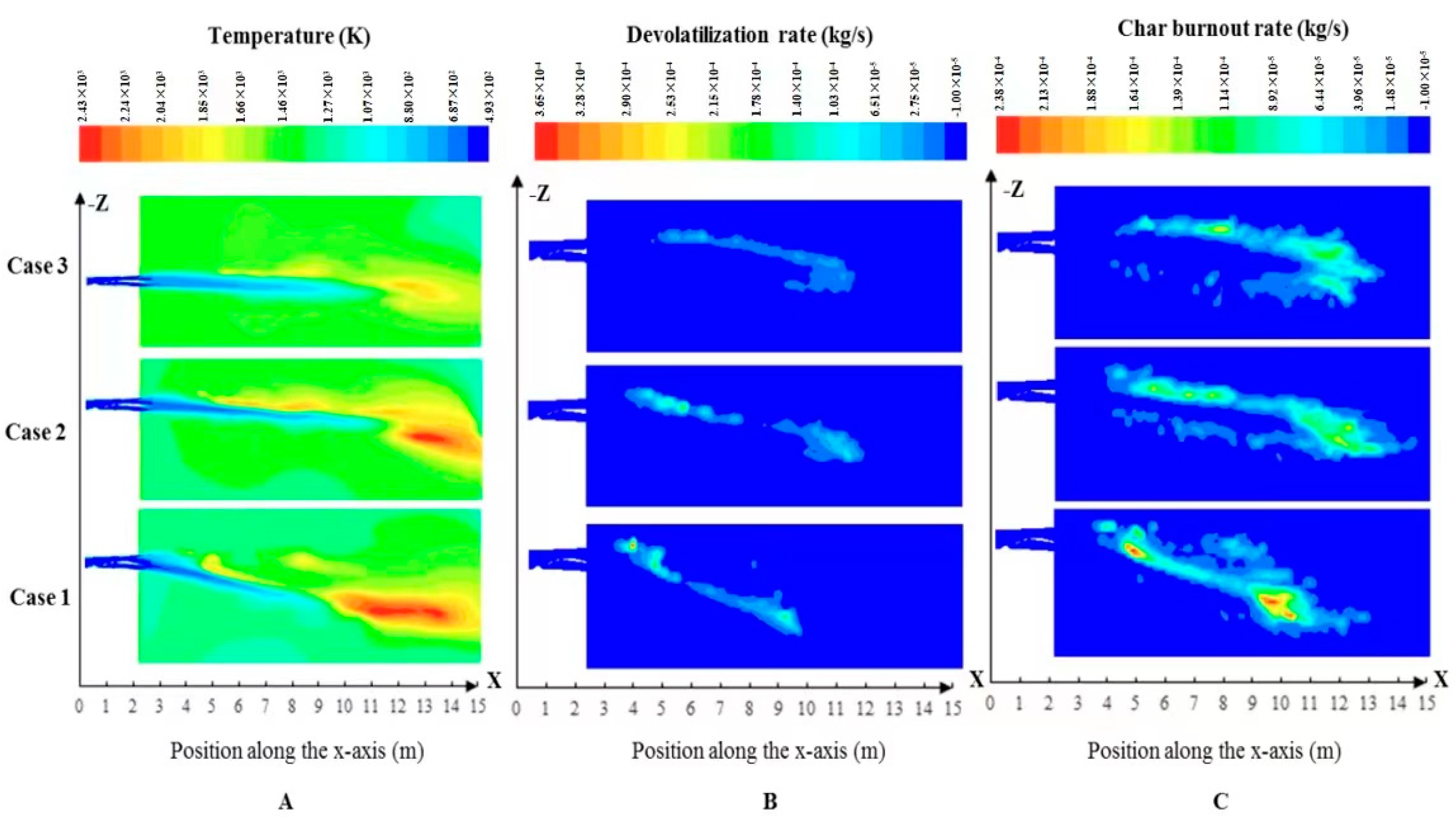
4.2.2. Combustion Characteristics

Figure 15 and Figure 16 show the combustion numerical simulation results of the three cases. The ignition of the pulverized coal particles in all three cases follows a progressive pattern, starting from the rich side and spreading towards the lean side. Ignition occurs at the edge around the pulverized coal bundle, where turbulent kinetic energy is intense. The strong turbulent kinetic energy facilitates convective heat transfer between the surrounding hot gas and the surface volatiles of the coal particles bundle and enhancing the ignition of the volatiles. Char combustion slightly lags behind volatile release in all three cases.
Case 1 exhibits earlier ignition compared to the other two cases, with volatile release occurring 1 m outside the nozzle and char combustion beginning 1.5 m outside the nozzle. Moreover, Case 1 demonstrates higher maximum volatile release rate and char burning rate than the other cases. However, the deflected jet flow in Case 1 increases the likelihood of flame scouring the water wall in the tangentially-fired boiler, potentially causing water wall corrosion [29]. Since the coal bundle tilts towards the lean side, the coal particles mix with the lean-side air earlier in Case 1, accelerating the combustion rate of the pulverized coal. Volatiles in Case 1 release earlier, char burns earlier, and the primary combustion zone was formed 7 m from the nozzle closer to the nozzle than in the other cases.
In Case 2, volatiles are released later than in Case 1 but earlier than Case 3. Char combustion commences later than in Case 1. Pyrolysis occurs in the range of 1.5–8 m from the nozzle, after which the primary combustion zone of the char formed. Figure 17 displays CO and CO2 concentrations distribution on the horizontal cross-section of three cases, reflecting the position of each reaction zone. The results show earlier volatilization and delayed char combustion in Case 2. In other words, coal in Case 2 undergoes an extended pyrolysis before ignition. Even though the volatiles’ release rate and char combustion rate in Case 2 were smaller than that in Case 1, both of them were greater than those in Case 3. The temperature contours in Figure 15 A show lower temperature in Case 3 compared to the other cases, indicating insufficient combustion. In conclusion, Case 2 facilitates stable combustion at low loads.

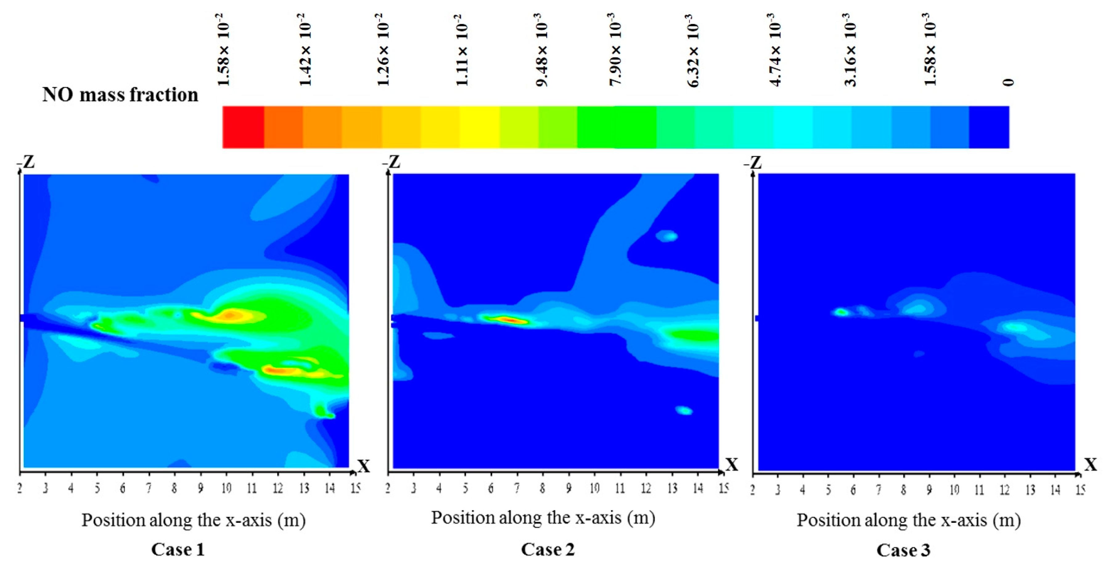
4.2.3. NOx Characteristics

As analyzed in Section 4.1.1, the DLNB effectively separated coal-air flow into rich and lean flows; therefore, both of these flows deviated from the stoichiometric ratio [30]. The rich coal-air flow accelerates volatile emission rates and consumes a large amount of oxygen, forming a reducing atmosphere, which inhibits volatile N generation. As mentioned above, the char particle bundle formed within the limited area of the nozzle acts as a reductant, effectively controlling on the char N from the burning of itself, which accounted for more than 60% of the total NOx emissions [31]. On the other hand, the lean coal-air flow burns under the fuel-lean combustion condition with high excess air coefficient, reducing the temperatures and the thermal NOx generation.
Figure 18 shows the NO concentration contours on the horizontal cross-section outside the burner for the three cases. The simulation results show average NO concentrations at furnace outlets of 1359.85 ppm, 552.52 ppm, and 400.46 ppm. According to the analysis of the combustion characteristics in Section 4.2.3, the fuel in Case 3 exhibits the lowest NO concentration as the fuel is not completely burnt.
In Case 2, the formation of a long and robust char bundle, along with progressive coal ignition and pyrolysis, leads to rapid gasification product generation and increased temperatures in the limited region. Then, oxygen concentration in the limited region decreases rapidly, creating a reducing atmosphere around the char bundle (Figure 17). Furthermore, Case 2 postponed the char combustion, enhancing the decoupling combustion condition, and simultaneously controlling the volatile N and char N. Therefore, the NOx control effect of Case 2 was the best, reducing average NO concentrations at the outlet by 59.37% compared to the initial design condition (Case 1).

4.3. DLNB Structure Optimization Summary

The coal particles in Case 1 flowed towards the coal-lean side, and the stream was short and divergent, leading to comparatively large Rq and Rv. As a result, volatiles in Case 1 released earlier and coal mixed with the lean side air earlier, so the char burned earlier. Finally, the NOx reduction is inhibited and the final NO concentration is the highest compared to the other cases. In Case 3, the rich-side space of burner nozzle was cut down, resulting in strong disturbance of the rich coal flow and leading to the discrete of pulverized coal and air. Eventually, the fuel was not completely burnt, so Case 3 exhibits the lowest NO concentration.
Comparatively, the nozzle structure of Case 2 effectively organized airflow, forming a long and stable coal particle jet with strong penetration. It achieved a rich/lean stream quantity ratio of 0.85, a rich/lean stream concentration ratio of 22.94. This design proves beneficial for highly efficient combustion of low volatile coal under low load and provides a reliable NOx heterogeneous reduction reaction bed, ensuring low-NOx emissions. Case 2 shows a clear partition between the beginning of volatile release and coke combustion and average final outlet NOx concentration of 552.52 ppm, which is 60% lower than the initial design.
In summary, the partition plate tilted at 0° exhibits good performance in terms of flow field distribution characteristics, concentration separation characteristics, combustion characteristics, and NOx generation characteristics.

5. Conclusions

This study aimed to develop a combustion technology for a low-volatile coal-fired burner under low load conditions. Analysis and optimization of the decoupling combustion low-NOx burner were conducted. The key findings and conclusions are drawn as follows:
(1)
The simulation results show that the separation and combustion capacities of the DLNB were preferred for the low-volatile coal over the LNB. The presence of a flame holder in the DLNB nozzle divides the coal/air flow into three streams, forming a long and stable pulverized coal bundle that provides beneficial ladder-shaped spontaneously steady combustion and ensures stable combustion ability.
(2)
Through optimization of the DLNB burner structure, the partition plate structure with a flat plate exhibited satisfying performance. It achieved a coal-rich/lean concentration ratio of 22.94 and reduced the average NOx emission concentration at the outlet by 59.37% compared to the initial design structure. As for combustion, DLNB shows ladder-shaped spontaneously steady combustion state, ensuring the combustion efficiency under low load. The outstanding low-NOx properties can be attributed to the long and robust penetrated char bundle, which enhances the decoupling combustion and effectively utilizes highly reductive volatile and char components to reduce NOx formation.

Author Contributions

Conceptualization and methodology, J.W.; Software, J.W. and J.Y.; Validation, J.Y. and F.Y.; Formal analysis, F.Y.; Data curation, J.W. and F.Y.; Writing—original draft, J.W. and J.Y.; Writing—review & editing, J.W. and F.C.; Visualization, J.W.; Supervision, F.C.; Funding acquisition, J.W. and F.C. All authors have read and agreed to the published version of the manuscript.

Funding

This work was funded by the National Key Research and Development Program of China grant number 2020YFB0606203.

Data Availability Statement

The data presented in this study are openly available in FigShare at https://figshare.com/search?q=10.6084%2Fm9.figshare.23269763 (accessed on 2 May 2023).

Acknowledgments

We thank Helen H. Lou of Lamar University for her academic assistance.

Conflicts of Interest

The authors declare no conflict of interest.

References

  1. Min, K.; Li, Z. Review of gas/particle flow, coal combustion, and NOx emission characteristics within down-fired boilers. Energy 2014, 69, 144–178. [Google Scholar]
  2. Tan, H.; Niu, Y.; Wang, X.; Xu, T.; Hui, S. Study of optimal pulverized coal concentration in a four-wall tangentially fired furnace. Appl. Energy 2011, 88, 1164–1168. [Google Scholar] [CrossRef]
  3. Kurose, R.; Ikeda, M.; Makino, H. Combustion characteristics of high ash coal in a pulverized coal combustion. Fuel 2001, 80, 1447–1455. [Google Scholar] [CrossRef]
  4. Kurose, R.; Ikeda, M.; Makino, H.; Kimoto, M.; Miyazaki, T. Pulverized coal combustion characteristics of high-fuel-ratio coals. Fuel 2004, 83, 1777–1785. [Google Scholar] [CrossRef]
  5. Kurose, R.; Makino, H.; Suzuki, A. Numerical analysis of pulverized coal combustion characteristics using advanced low-NOx burner. Fuel 2004, 83, 693–703. [Google Scholar] [CrossRef]
  6. Kurose, R.; Tsuji, H.; Makino, H. Effects of moisture in coal on pulverized coal combustion characteristics. Fuel 2001, 80, 1457–1465. [Google Scholar] [CrossRef]
  7. Yang, W.; Wang, B.; Lei, S.; Wang, K.; Chen, T.; Song, Z.; Ma, C.; Zhou, Y.; Sun, L. Combustion optimization and NOx reduction of a 600 MWe down-fired boiler by rearrangement of swirl burner and introduction of separated over-fire air. J. Clean. Prod. 2019, 210, 1120–1130. [Google Scholar] [CrossRef]
  8. Li, Z.; Liu, G.; Zhu, Q.; Chen, Z.; Feng, R. Combustion and NOx emission characteristics of a retrofitted down-fired 660 MW utility boiler at different loads. Appl. Energy 2011, 88, 2400–2406. [Google Scholar] [CrossRef]
  9. Song, L.; Chen, Z.; He, E.; Jiang, B.; Li, Z.; Wang, Q. Combustion characteristics and NOx formation of a retrofitted low-volatile coal-fired 330 MW utility boiler under various loads with deep-air-staging. Appl. Therm. Eng. 2017, 110, 223–233. [Google Scholar]
  10. Fang, Q.; Wang, H.; Zhou, H.; Lei, L.; Duan, X. Improving the Performance of a 300 MW Down-Fired Pulverized-Coal Utility Boiler by Inclining Downward the F-Layer Secondary Air. Energy Fuels 2010, 24, 4857–4865. [Google Scholar] [CrossRef]
  11. Lun, M.; Fang, Q.; Peng, T.; Cheng, Z.; Gang, C.; Lv, D.; Duan, X.; Chen, Y. Effect of the separated overfire air location on the combustion optimization and NO x reduction of a 600 MW e FW down-fired utility boiler with a novel combustion system. Appl. Energy 2016, 180, 104–115. [Google Scholar]
  12. Ma, L.; Fang, Q.; Lv, D.; Zhang, C.; Chen, Y.; Chen, G.; Duan, X.; Wang, X. Reducing NOx Emissions for a 600 MWe Down-Fired Pulverized-Coal Utility Boiler by Applying a Novel Combustion System. Environ. Sci. Technol. 2015, 49, 13040–13049. [Google Scholar] [CrossRef] [PubMed]
  13. Kuang, M.; Li, Z.; Liu, C.; Zhu, Q.; Zhang, Y.; Wang, Y. Evaluation of overfire air behavior for a down-fired 350 MWe utility boiler with multiple injection and multiple staging. Appl. Therm. Eng. 2012, 48, 164–175. [Google Scholar] [CrossRef]
  14. Shi, X.; Qian, E.; Shi, H.; Zheng, C. Investigation of the Optimization of Slit Width for a Slitted Bluff-body Burner: Pulverized Coal Ignition and Flame Stabilization. Combust. Sci. Technol. 1997, 124, 1–15. [Google Scholar]
  15. Hao, Z.; Yu, Y.; Liu, H.; Hang, Q. Numerical simulation of the combustion characteristics of a low NOx swirl burner: Influence of the primary air pipe. Fuel 2014, 130, 168–176. [Google Scholar]
  16. Wang, X.; Tan, H.; Yan, W.; Wei, X.; Niu, Y.; Hui, S.; Xu, T. Determining the optimum coal concentration in a general tangential-fired furnace with rich-lean burners: From a bench-scale to a pilot-scale study. Appl. Therm. Eng. 2014, 73, 371–379. [Google Scholar] [CrossRef]
  17. Zhou, H.; Cen, K.; Fan, J. Two-Phase Flow Measurements of a Gas−Solid Jet Downstream of Fuel Rich/Lean Burner. Energy Fuels 2005, 19, 64–72. [Google Scholar] [CrossRef]
  18. Maier, H.; Spliethoff, H.; Kicherer, A.; Fingerle, A.; Hein, K.R.G. Effect of coal blending and particle size on NOx emission and burnout. Fuel 1994, 73, 1447–1452. [Google Scholar] [CrossRef]
  19. Shi, X.; Qian, R.; Zhen, Y.; Ma, X. A new principle of ignition and flame stability for low-volatile pulverized coal with slitted bluff-body burner. Int. J. Energy Res. 2015, 20, 933–941. [Google Scholar]
  20. Wei, X.; Xu, T.; Hui, S. Burning low volatile fuel in tangentially fired furnaces with fuel rich/lean burners. Energy Convers. Manag. 2004, 45, 725–735. [Google Scholar] [CrossRef]
  21. Cai, L.; Xiao, S.; Gao, S.; Yin, W.; Dong, L.I.; Guangwen, X.U. Low-NOx coal combustion via combining decoupling combustion and gas reburning. Fuel 2013, 112, 695–703. [Google Scholar] [CrossRef]
  22. Smoot, L.D.; Hill, S.C.; Xu, H. NOx control through reburning1This mini-review paper was presented, together with a series of other review papers, at the Tenth Annual Technical Conference of the Advanced Combustion Engineering Research Center, held in Salt Lake City, Utah, in March 1997.1. Prog. Energy Combust. Sci. 1998, 24, 385–408. [Google Scholar]
  23. Kramlich, J.C.; Cole, J.A.; McCarthy, J.M.; Lanier, W.S.; McSorley, J.A. Mechanisms of nitrous oxide formation in coal flames. Combust. Flame 1989, 77, 375–384. [Google Scholar] [CrossRef]
  24. Wang, J.; Zheng, K.; Singh, R.; Lou, H.; Hao, J.; Wang, B.; Cheng, F. Numerical simulation and cold experimental research of a low-NOx combustion technology for pulverized low-volatile coal. Appl. Therm. Eng. 2017, 114, 498–510. [Google Scholar] [CrossRef]
  25. Kobayashi, H.; Howard, J.B.; Sarofim, A.F. Coal devolatilization at high temperatures. Symp. Combust. 1977, 16, 411–425. [Google Scholar] [CrossRef]
  26. Chen, H. Research on Stable Combustion Technology of Boiler Burning Inferior Coal at Low Load. Master’s Thesis, North China Electric Power University, Beijing, China, 2013. [Google Scholar]
  27. Gururajan, V.S.; Wall, T.F.; Gupta, R.P.; Truelove, J.S. Mechanisms for the ignition of pulverized coal particles. Combust. Flame 1990, 81, 119–132. [Google Scholar] [CrossRef]
  28. Wang, J.; Lou, H.H.; Yang, F.; Cheng, F. Numerical simulation of a decoupling and Re-burning combinative Low-NOx coal grate boiler. J. Clean. Prod. 2018, 188, 977–988. [Google Scholar] [CrossRef]
  29. Gandhi, M.B.; Vuthaluru, R.; Vuthaluru, H.; French, D.; Shah, K. CFD based prediction of erosion rate in large scale wall-fired boiler. Appl. Therm. Eng. 2012, 42, 90–100. [Google Scholar] [CrossRef]
  30. Zhu, Q. Study on NOx Generation Mechanism of Large Boiler and Flame Denitration Numerical Simulation of Burner. Ph.D. Thesis, Huazhong University of Science and Technology, Wuhan, China, 2001. [Google Scholar]
  31. He, J. Experimental Study of NO Emission in Combustion of Coal in Fixed Bed. J. Heilongjiang Inst. Sci. Technol. 2013, 23, 21–25. [Google Scholar]
Figure 1. Schematic diagram of the DLNB: (a) front view, (b) top view; Bi represents the velocity measure point, (c) left view (with the fictitious furnace chamber). (Unit: m).
Energies 16 04474 g001aEnergies 16 04474 g001b
Figure 2. The actual photo of the experimental burner.
Energies 16 04474 g002
Figure 3. The meshed domain of the burner: (a) the top view, (b) the zoomed view.
Energies 16 04474 g003
Figure 4. Schematic drawing of the LNB burner: (a) the nozzle structure (b) the burner body (with fictitious furnace chamber).
Energies 16 04474 g004
Figure 5. The velocity distribution along the z-axis on the plane S1 of DLNB.
Energies 16 04474 g005
Figure 6. The particle concentration contour of the central horizontal cross-section (Z and X plane) (kg·m−3): (A) DLNB, (B) LNB.
Energies 16 04474 g006
Figure 7. The particle concentration contour on the outlet vertical cross-section of two kinds of burners (kg·m−3): (A) Plane S1 of DLNB, (B) Plane S2 of LNB.
Energies 16 04474 g007
Figure 8. Particle concentration distribution of the central horizontal cross-section (X and Z plane): (A) DLNB, (B) LNB.
Energies 16 04474 g008
Figure 9. The temperature and de-volatilization rate distribution of the central horizontal cross-section (X and Z plane): (A) DLNB, (B) LNB.
Energies 16 04474 g009
Figure 10. The char combustion rate and CO2 concentration distribution of the central horizontal cross-section (X and Z plane): (A) DLNB, (B) LNB.
Energies 16 04474 g010
Figure 11. The contours of the velocity of the central horizontal cross-section (X and Z plane): (A) DLNB, (B) LNB. And turbulent kinetic energy of the outlet vertical cross-section: (A) Plane S1 of DLNB, (B) Plane S2 of LNB.
Energies 16 04474 g011
Figure 12. Particle concentration contours (kg·m−3) of: (A) the central horizontal cross-section (X and Z plane), (B) the central vertical cross-section (X and Y plane).
Energies 16 04474 g012
Figure 13. The: (A) turbulent kinetic energy (Km2·s−2), (B) velocity (m·s−1) contour on the central cross section.
Energies 16 04474 g013
Figure 14. The velocity streamline diagram of pulverized coal particles in XZ plane, Y = 0.
Energies 16 04474 g014
Figure 15. The contours of: (A) Temperature (K), (B) de-volatilization rate (kg·s−1) and (C) char burnout rate (kg·s−1) of the central horizontal cross-section.
Energies 16 04474 g015
Figure 16. The 3-Dimensional temperature fields (K) of all three cases.
Energies 16 04474 g016
Figure 17. The contours of: (A) CO mass fraction and (B) CO2 mass fraction of the central horizontal cross-section.
Energies 16 04474 g017
Figure 18. NOx mass fraction contours of the central horizontal cross-section.
Energies 16 04474 g018
Table 1. Models utilized in this numerical simulation.
Simulation ObjectModel/Algorithm Selection
Turbulent flowRealizable k-ε two-equation model
Gas–solid two-phase turbulent flowLagrangian particle trajectories model
RadiationP-1 model
DevolatilizationTwo-competing rate model
Gas-phase turbulent combustionPDF model
Char surface combustionKinetic/diffusion surface reaction rate model
The fuel NOx formationDe Soete mechanisms
The thermal NOx formationExtended Zeldovich mechanisms
Table 2. Proximate analysis and heat value results.
SampleProximate Analysis (wt%)Qnet,ar
(kcal·kg−1)
MarAdVdFCd
Meager coal5.6729.2012.4958.315497.00
Note: Mar: moisture value as received Ad: dry basis ash Vd: dry basis volatile. FCd: dry basis fixed carbon. Qnet,ar: net heat value as received.
Table 3. The parameters of structure optimization.
CaseAnglesRich/Lean SideCross Area [m2]
1Tilt to lean side 10°Rich0.08876
Lean0.09167
2Rich0.06117
Lean0.09167
3Tilt to rich side 3°Rich0.05298
Lean0.09167
Table 4. Separation characteristic parameters of DLNB and LNB.
RqRcRn
DLNB1.3016.300.20
LNB1.041.370.03
Table 5. Separation characteristic data.
CaseRich/Lean Side kg·(kg·Air)−1Equivalent RatioRcRqRv
1richCn0.711.0416.281.301.39
leanCd0.040.06
2richCn1.432.1022.940.851.29
leanCd0.060.09
3richCn0.420.6215.420.711.24
leanCd0.030.04
Disclaimer/Publisher’s Note: The statements, opinions and data contained in all publications are solely those of the individual author(s) and contributor(s) and not of MDPI and/or the editor(s). MDPI and/or the editor(s) disclaim responsibility for any injury to people or property resulting from any ideas, methods, instructions or products referred to in the content.

