Article

Contribution to Active Thermal Protection Research—Part 1 Analysis of Energy Functions by Parametric Study

1
Department of Building Services, Faculty of Civil Engineering, Slovak University of Technology, 810 05 Bratislava, Slovakia
2
Department of Building Construction, Faculty of Civil Engineering, Slovak University of Technology, 810 05 Bratislava, Slovakia
3
Department of Building Technology, Faculty of Civil Engineering, Slovak University of Technology, Radlinského 11, 810 05 Bratislava, Slovakia
4
Engineer in the Field of Energy Efficiency of Buildings, 851 05 Bratislava, Slovakia
*
Author to whom correspondence should be addressed.
Energies 2023, 16(11), 4391; https://doi.org/10.3390/en16114391
Submission received: 30 March 2023 / Revised: 5 May 2023 / Accepted: 19 May 2023 / Published: 29 May 2023

Abstract

:
The thermal energy consumption for heating objects is one of the main parameters deciding their technical and structural solution. Reducing energy consumption is realized in various ways. The most used method is passive thermal protection, that is, increasing the thermal insulation parameters of the envelope constructions and optimizing the operation of the technical equipment of the buildings. There are also methods of active thermal protection to reduce heat leakage through non-transparent parts of the building envelope. Active thermal protection (ATP) is a dynamic process that applies primarily to building structures with integrated energetically active elements that fulfill one or more functions in mutually exclusive operating modes of energy systems and heat sources, such as thermal barriers (TB), large-scale heating/cooling, long-term heat/cool storage, capturing solar energy, and energy from the surroundings or even recovering heat in the cold season or cold in the warm season and other combinations. The research area focuses on analyzing active thermal protection’s energy potential. The methodology is based on a parametric study of dynamic thermal resistance (DTR), and heat flows to the interior and exterior from ATP for the investigated envelope of the experimental house EB2020 made of aerated concrete blocks. Such constructions generally show a consistently high DTR of 11.8 to 30.8 ((m2·K)/W) at a low mean heat transfer temperature of 10 to 16 °C, corresponding to the thermal insulation of 300 to 1000 mm. In the case of ATP storage heating with an average temperature of the heat-carrying substance of 30 °C, the heat flow into the interior of the investigated structure would be only 2.31 W/m2. Therefore, they are only suitable for a thermal barrier and heat/cold accumulation. Based on the synthesis and induction of analogical forms of the results of previous research into recommendations for the design of individual energy functions of ATP for perimeter structures of buildings, we present heat flows to the interior/exterior when changing the material of the layers towards the interior from ATP and describe possible variants of the development of building structures with integrated energetically active elements.

1. Introduction

An area of research that our research team has been involved in for several years is the detailed investigation of combined building-energy systems (CBES) using renewable energy sources (RES) or waste heat/cooling. Individual countries in the European Union and worldwide aim to achieve carbon neutrality in the building sector to create a link with the construction of energy-self-sufficient and environmentally safe buildings. The current question is whether it is necessary to continually introduce more costly and energy-intensive technologies and energy systems to achieve the required reduction in carbon dioxide emissions. Probably, it is precisely the CBES systems with embedded energy-active elements in selected building structures that offer technical solutions that provide high energy potential and a relatively inexpensive application without the need to increase further the investment costs for the construction of the buildings mentioned above.
In general, CBES that acts as a heat or cold source are quite well known, such as energy (solar) roofs (ESR) with built-in tubular absorbers (solar thermal energy), ground heat storages (GHS), and ground air/liquid heat exchangers (GHE), which are used for forced ventilation of buildings with the application of energy recovery from waste air. Wall and roof absorbers (WRA), which are integrated into the building structure on the outside envelope side of the building, are used in conjunction with heat pumps to capture solar or ambient energy. These can be constructed either on the building slab or underneath the building. Also worth mentioning are the integrated photovoltaic systems in buildings (BiPV). However, end-use applications of energy systems also include large-scale radiant low-temperature heating or high-temperature cooling, thermally activated building structures (TABS), and active thermal protection (ATP).
One of the main tasks in our research is to pay sufficient attention to the detailed analysis of different building structures that have incorporated energy-active elements, especially with the function of active thermal protection, which permanently uses the energy from energetic solar roofs accumulated in long-term ground heat reservoirs when applied in residential buildings, namely in single-family houses. Active thermal protection (ATP) is a dynamic process that primarily applies to building structures with integrated energy-active elements that serve one or more functions in mutually exclusive operating modes of energy systems and heat sources, such as thermal barrier (TB), large-scale heating/cooling, long-term heat/cold storage, solar and ambient energy capture, or even heat recovery in the cold season or cold in the warm season, and other combinations. A detailed, comprehensive overview of attractive technical solutions and professional and scientific treatises in the field of active thermal protection is presented in Section 2. We are conducting research based on the reuse of already well-known technologies characterized by advanced solutions. In this paper, we analyze the energy functions and potential of the envelope of the experimental house EB2020 made of aerated concrete blocks using a parametric study of the dynamic thermal resistance (DTR) and the heat fluxes to the interior and exterior from the ATP. The novelty of our research lies in the incorporation of variant peak heat sources with RES-based heat/cooling sources (such as solar energy roof, ground source heat/cooling reservoir) and in the creation of an entirely new, original way of operation of heat/cooling sources and energy systems with the possibility of changing and combining the operating modes of active thermal protection (thermal barrier, heating, cooling, etc.). Our contribution to RES research has already been presented in a paper listed in the literature as [1] and to GHS research in a paper in the literature as [2].
Our scientific research aims to determine the efficiency and energy efficiency of combined building-energy systems through detailed calculations and long-term experimental measurements. In this paper, using a parametric study, we rigorously analyze the energy potential of active thermal protection for residential buildings. A more detailed description of the sub-objectives and research methodology, i.e., a description of the planning, organization, and implementation of the research, is presented in Section 3. Section 4 offers a comprehensive and meaningfully classified summary of our research achievements. Specifically, it includes a mathematical–physical model of a selected fragment of the building envelope, an evaluation of the analyzed physical quantities in the form of tabular and diagrammatic graphical outputs, and the energy potential of ATP in different energy functions. In the discussion and conclusions, specifically in Section 5, based on a detailed analysis, the synthesis and induction of analogous forms of previous research result into recommendations for the design of individual ATP energy functions for building envelopes, we present the heat fluxes to the interior/exterior when the material of the layers is changed towards the interior from the ATP; we evaluate under which specific conditions it is worthwhile to effectively use active thermal protection that performs the function of a thermal barrier, wall heating/cooling; and describe possible options for the development of building structures with integrated energy-active elements.
In this paper, we present a parametric study that is valid only for the steady state. The transient state, in which all parameters change over time, will be determined by upcoming computer simulations. The analysis and comparison of the results in both regimes will be presented in future research work.

2. Overview of Technical Solutions and Scientific Works in the Field of ATP

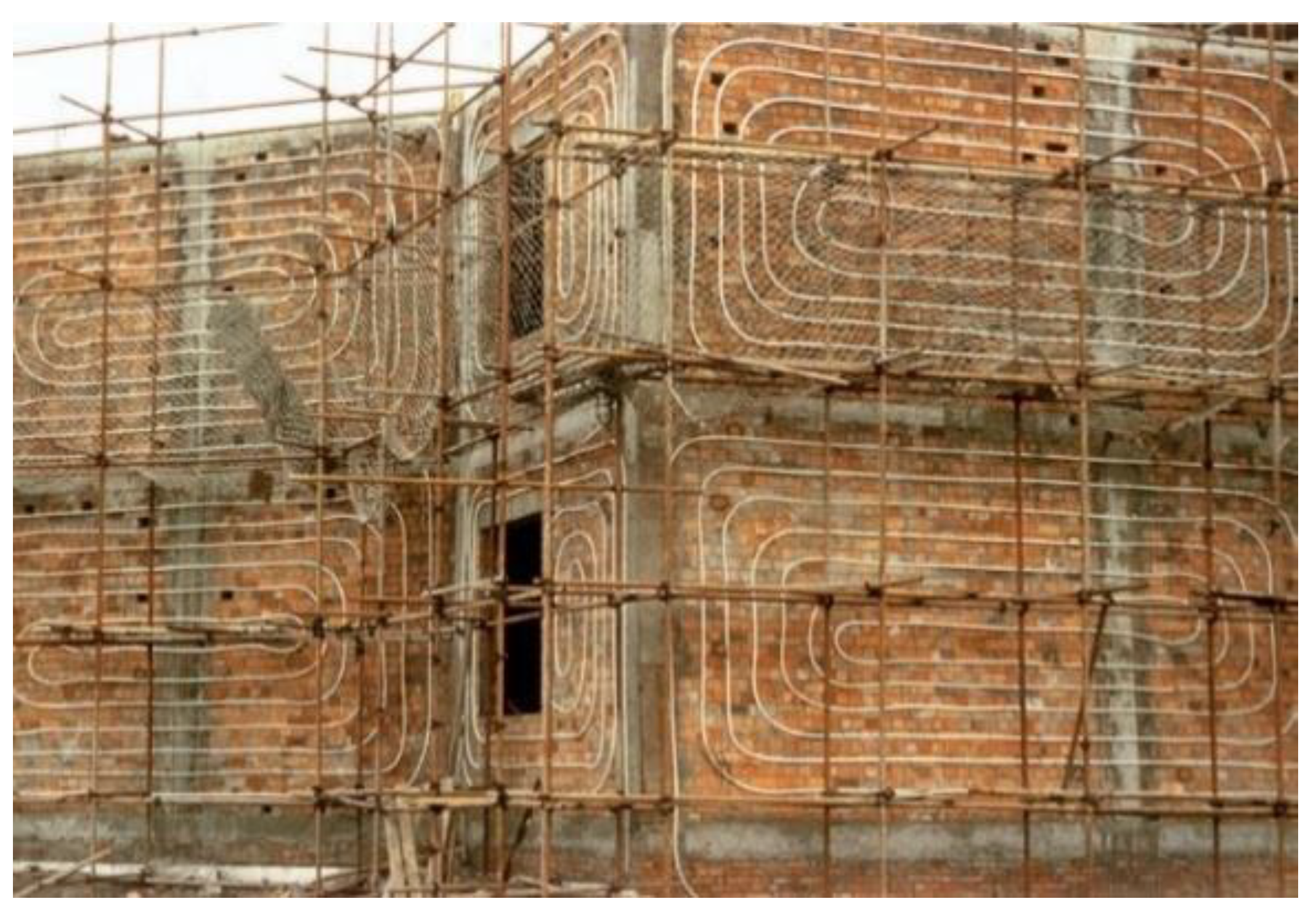
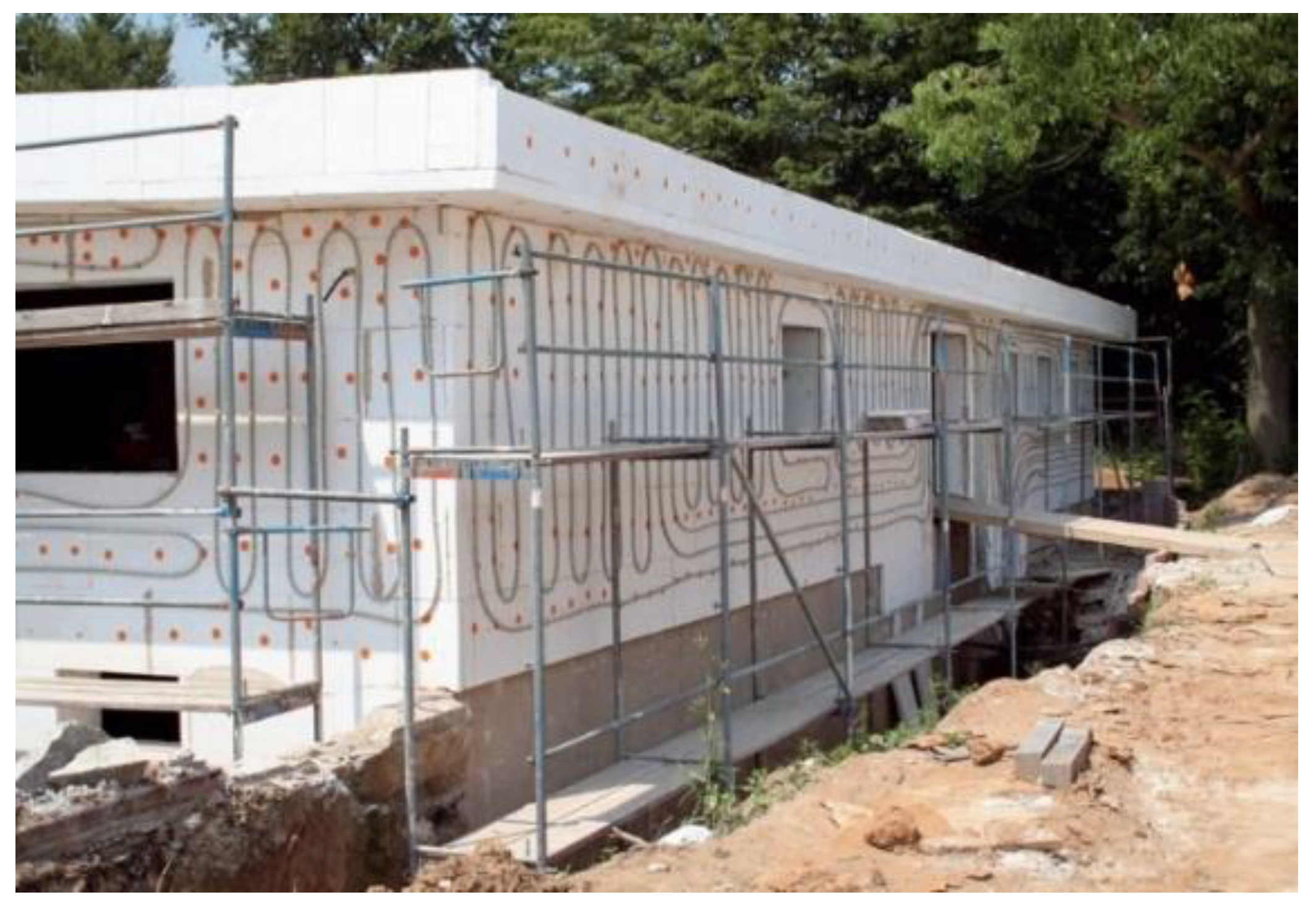
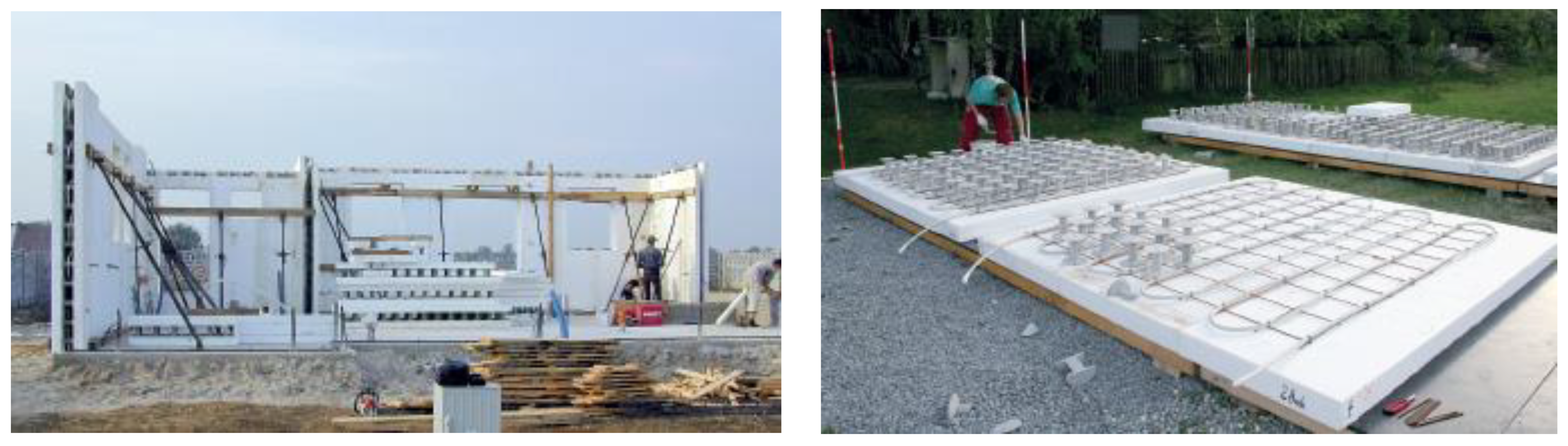
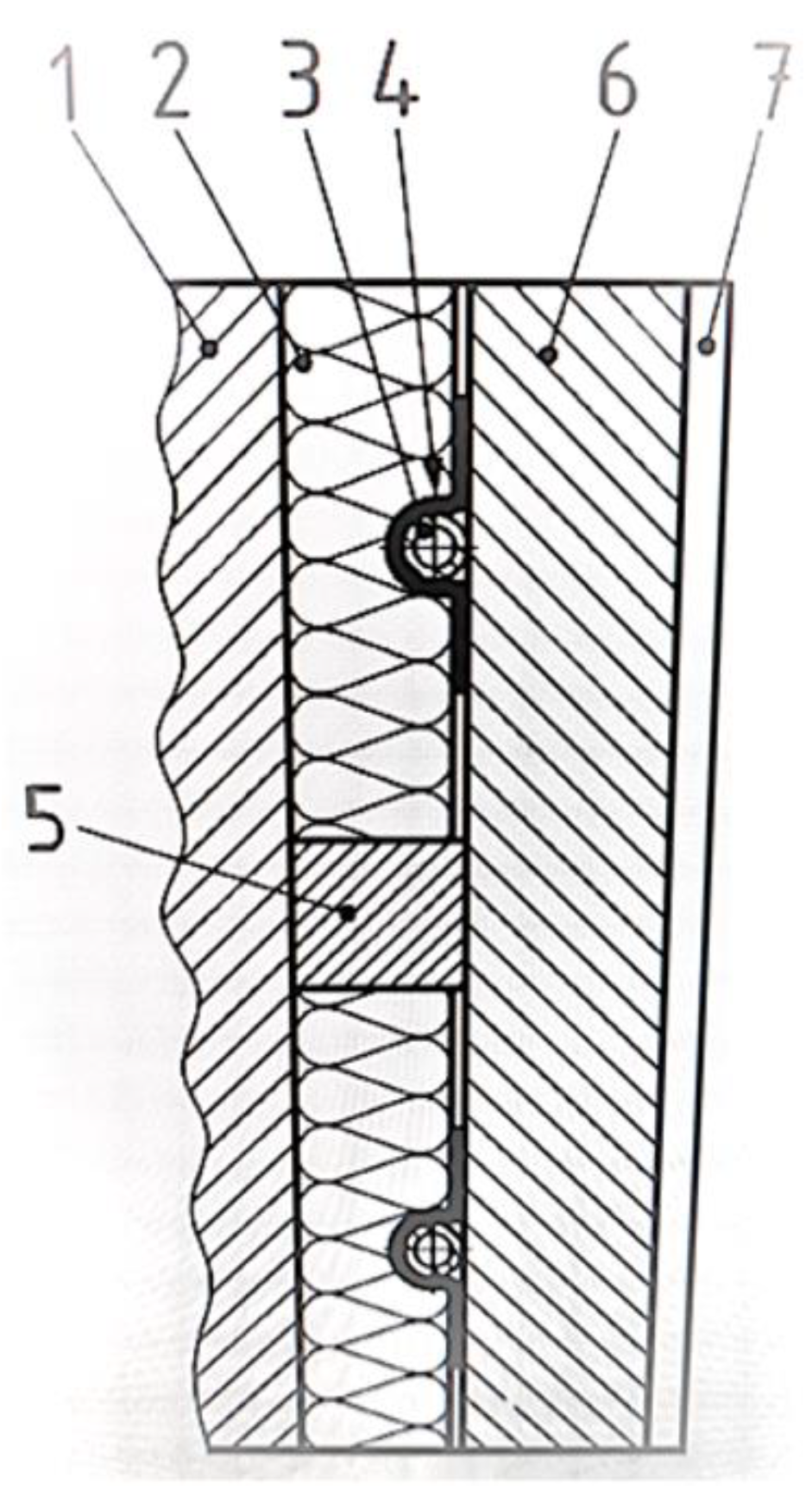
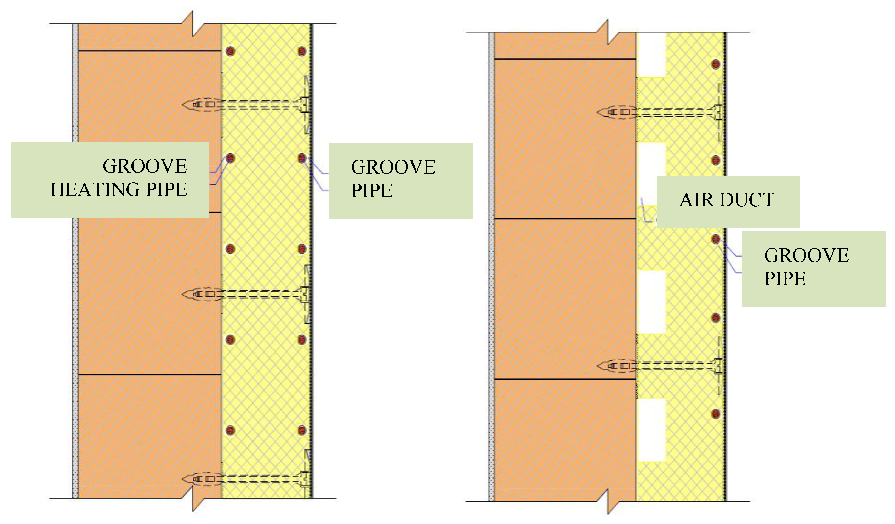
2.1. The Initial Technical Solution for Our Research

The topic of active thermal protection (ATP) is being studied by many researchers and scientists worldwide. The development and concrete application of the thermal barrier as one of the functions of ATP in practice has been significantly addressed by Dipl.-Ing., Phys. Edmond D. Krecké. Using solar energy captured by ESR and stored in long-term GHS, he created the patented the ISOMAX system for application in residential buildings [3]. The beginning of the construction of buildings with this system dates back to the 1990s and continues to this day. The ISOMAX system implements ATP in the TB function in three basic variants. The first is the application between the load-bearing part of the multilayer building structure and the thermal insulation (Figure 1); the next is between the load-bearing part of the multilayer building structure and the thermal insulation, at the same time on the exterior side of the thermal insulation for the application of heat from the unfrozen depth of the soil (Figure 2); and, finally, the application in the reinforced concrete core of the building envelope, which is concreted directly on the building site using the so-called lost EPS formwork (Figure 3).

2.2. Review of Scientific and Research Publications in the Field of Building Structures with Integrated Energy-Active Elements

In this section, we provide a helpful overview of the most relevant scientific and research publications in the field of building construction that deal with integrated energy-active elements. The authors of these papers record a worldwide coverage.
M. Krajčík, O. Šikula, 2020 [4], in their work are devoted to a detailed structural description and subsequent mutual comparison of four variants of wall cooling systems, three of which are potentially suitable for the reconstruction of the building. In addition to using established performance indicators, they present an indicator called heat transfer efficiency, which, by its very nature, allows the detection of even minor differences in the thermal dynamics of mutually different systems. For example, design systems with tubes below the surface provide higher cooling performance and are very sensitive to the axial distance of the tubes placed between each other. Conversely, systems with tubes buried in the core allow heat accumulation and are sensitive to the thickness of the thermal insulation.
In another article by M. Krajčík, M. Arıcı, O. Šikula, and M. Šimko, 2021 [5], the authors give a brief overview of the research and group it into subtopics, which are discussed in detail. The subtopics of indoor heating and cooling include thermal performance, thermal comfort, renewable energy issues, their use in building renovation, and their combination with phase change materials (PCM). In the case of TB, the authors discuss the principle of operation, types, design, and heating and cooling performance. Based on recommendations from the scientific literature, they divide their classification systems for TBs and wall-mounted heating and cooling systems. The benefits and drawbacks are outlined, and design suggestions for wall-mounted systems are given.
Authors M. Krajčík, M. Šimko, O. Šikula, D. Szabó, D. Petráš, 2021 [6] describe radiant wall heating and cooling with tubes that are structurally attached to thermal insulation bricks. As they state, this system is particularly suitable for reconstructing buildings because of its affordability and ease of installation, but this method can also be used in new buildings. The thermal performance and storage response, the wall surface temperature, the temperature in the cross-section of the tubes, and the temperature of the energy-carrying substance-water were measured at different heat loads. A step-by-step analysis of the problem concluded that a low-conductivity core significantly reduces heat loss, meaning the system can function properly even without thermal insulation. Numerical simulations at the room level under study showed that placing the system on one wall leads to an inhomogeneous thermal environment. They recommend installing the system on several walls simultaneously, which may be a more appropriate solution to achieve more uniform thermal comfort conditions in the human living area.
B. Junasová, M. Krajčík, O. Šikula, M. Arıcı, M. Šimko, 2022 [7] cite studies that looked at how to modify the layout of a ceiling and wall system with pipes below the surface and a wall system with a pipe as a fragment inserted directly into the masonry. A verified numerical model was used to calculate heat transfer. A conductive core was used to determine that an internal wall might have up to 30 mm thick insulation. Even with a core thickness of only 150 mm, no insulation was necessary because of the insulating core. The performance increase to 10 mm axial tube spacing was maximum at 60 mm. Spacing below 30 mm was judged to be ineffective. By generating a homogeneous surface temperature, the narrow spacing increased system output to energy input while decreasing response time. The output was boosted by adding a metal fin to the pipe in the plaster layer, and as a result, the pipe spacing was decreased from 100 to 60 mm (particularly by 14 W/m2, or 20%). For a small design, attaching the metal fin to a pipe covered in insulation yielded a performance that was consistently highest among all the examples investigated. On the other hand, adding a bricklayer to the conductive wall and inserting the pipe there did not boost the wall’s ability to store heat.
M. Šimko, D. Petráš, M. Krajčík, D. Szabó, 2022 [8] tested with warm weather circumstances that are characteristic of summer in northern and central Europe. A climate chamber was used to simulate the outdoor atmosphere, and a hot box was mounted to the wall to replicate the indoor environment. Through the use of 2D numerical simulations, it was determined how sensitive the thermal performance was to various physical design characteristics. The measurements revealed that the wall system had a quick heat response. The cooling capability was found to be 38.3 W/m2 of cooling surface area or about 4.8 W/m2 per 1 K temperature difference between the water and the hotbox. A temperature of 19.6 °C was recorded as the lowest surface temperature right near the duct. Therefore, the cooling efficiency might be improved by bringing the surface temperature closer to the dew point temperature. The water inside the pipe had a remarkably similar temperature to the pipe’s surface temperature. This experiment demonstrated how the tested wall cooling system’s characteristic favors the effectiveness and cooling capabilities of the air-to-water heat pump.
Another author team consisting of E. Krecké, R. Ulbrich, G. Radlak, 2007 [9] presents the technology of the patented ISOMAX system, which combines the advantages of solar and geothermal energy. By presenting several examples already implemented in all climatic zones, they verify the efficiency of this system, which appears to be extremely favorable in terms of investment and operating costs. To optimize and ‘calculate’ this building technology, the authors admit that further research and development are needed. This future research aims to gain control over calculating heat exchange processes and optimize insulation thicknesses.
M. Krzaczek, Z. Kowalczuk, 2011 [10] elucidate the idea of a thermal barrier (TB), an indirect heating and cooling system for residential buildings powered by solar thermal radiation. It is made of polypropylene U-tubes positioned inside the exterior envelope walls. This paper’s major goal is to look into the thermal stability and performance of the thermal barrier. First, a 3D FE model of a prefabricated outside wall component with a TB U-pipe system and fluid flow is created using the FE code ABAQUS.
Zhang Zhigang, Sun Zhijian, Duan Caixia, 2014 [11] proposed wall-implanted heat pipes (WIHP), a novel kind of passive solar energy use technique. They looked at heat transport efficiency and energy-saving features using normal Jinan meteorological data, first theoretically and then experimentally. The findings show that the experimental results and the theoretical hypotheses match up fairly well. WIHP’s heat transfer performance may be adjusted and controlled by lowering the heating load and enhancing the thermal environment.
S.H. Park, W.J. Chung, M.S. Yeo, K.W. Kim, 2014 [12] conducted simulation research that calculated the energy usage and thermal comfort of a thermally activated building system (TABS) combined with radiant floor heating and a forced ventilation system integrated with cooling in a typical residential building. Using the EnergyPlus software, two residential buildings with various envelope types were modeled. This study suggests combining the present system with a TABS heating and cooling system. The applications, especially for buildings with moderate thermal loads, show that TABS paired with the present system is thermally comfortable and energy efficient.
The author M. Doležel, 2014 [13] focused in his work mainly on the mutual comparison of temperatures in the wall construction with and without the TB system and the determination of external temperatures at which it is appropriate to implement the construction with TB. However, these TB designs also reduce heat transfer through opaque building structures, which is only one part of the total heat loss; therefore, the payback period and the primary energy consumption of the TB system compared to traditional buildings are questionable.
B. Stojanovic, J. Janevski, P. Mitkovic, M. Stojanovic, M. Ignjatovic, 2014 [14] specifically focus on the opaque portion of the building envelope with integrated thermally actuated building technologies in their study. The energy requirements for heating a genuine apartment complex constructed in Serbia were discovered by the authors using EnergyPlus software. With the aid of the Open Studio Plug-in, the building was modeled in Google SketchUp, along with all of the simulation’s inputs. The generated results were contrasted with the actual heating energy consumption that had been measured. The findings indicate that thermally activated building systems are an effective way to boost a building’s energy efficiency and that, in addition, a low-energy house class standard can be reached by applying specific temperatures inside this feature.
Babiak, Jan; Vagiannis, Georgios, 2015 [15] conducted a study comparing TABS with traditional convective air conditioning and fan coil systems in office buildings of an administrative nature, specifically in two locations in France, Paris, and Lyon. The current study presents the results for Lyon. The life cycle cost (LCC) analysis evaluates different heating, cooling, and forced ventilation methods. Investment and operating cost data and building energy simulations show that TABS performs more efficiently and, thus, reduces the building’s global cost (or lifetime cost) quite significantly compared to considering other forced-air mechanical HVAC schemes. TABS has proven adaptable and cost-effective, especially for French building conditions.
A. Li, X. Xu, Y. Sun, 2016 [16] propose a novel low-grade energy recovery system, i.e., a wall with an integrated pipe coupled with a ground heat exchanger. Its energy-saving potential in five typical climatic regions of China is investigated. A real-scale building energy simulation platform has been developed to estimate the energy-saving potential. A multi-criteria performance evaluation was performed to find the optimal size of the low-energy system in each climatic region.
T. Kisilewicz, M. Fedorczak-Cisak, T. Barkanyi, 2019 [17] describe the preliminary findings and analyses of a study conducted in a residential building in Nyiregyhaza, Hungary, that was being experimentally observed. An innovative system of the direct connection between a ground heat exchanger and a wall heat exchanger is installed in the residential structure. The authors of this work make an effort to provide an answer to the question of how much an active insulation system can take the place of the passive insulation systems that are now in use.
Author team Krzaczek, M., Florczuk, J., and Tejchman, J. J. A. E., 2019 [18] describe an improved and efficient energy management technique in piped heating/cooling system called a thermal barrier. A thermal barrier is a technique aimed at managing and controlling the heat input to and heat output from external envelope walls with integrated ductwork. A specialized fuzzy logic algorithm synchronizes the heat supply/removal with the varying heat load and fully controls the installed piped heating/cooling system. For a particular reference temperature of the pseudo-surface created by the embedded pipe system of the wall heat exchanger, the basic operating principle of the thermal barrier is to maintain the internal energy variation of the wall as near to zero as possible. Detailed field measurement results and an illustration of a thermal barrier system installed in a two-story residential structure are shown. These experimental findings attest to the thermal barrier’s great efficiency and its propensity to effectively regulate indoor climate by utilizing low-grade heat and cold sources. In the cold season, the supply water temperature was extremely low (25.3 °C); in the warm season, it was extremely high (20.5 °C). Throughout the year, the daily changes in indoor air temperature did not surpass 0.8 °C. The thermal barrier system only used a low-quality renewable chiller to operate in cooling mode throughout the summer. It was also discovered that the thermal barrier’s flexibility made it possible to utilize heating and cooling systems other than those used in the test home.
Figiel E, Leciej-Pirczewska D., 2020 [19] analyze a water-based thermo-active wall barrier where the pipes are integrated directly into the wall structure. The research and subsequent analysis of the obtained data led the authors to calculations that showed that the thermo-active wall barrier is highly sensitive to the location of the pipes. The impact of the thermal barrier on the building’s energy efficiency is also examined in the paper that comes after this one. Furthermore, based on variables gathered from a specific Polish meteorological database, an analysis was conducted for a home in a region with a temperate environment. According to calculations made using the current method for assessing the energy performance of buildings, the thermal barrier can help to significantly reduce thermal energy transfer losses, which will lessen the system’s negative environmental impact.

2.3. Overview of Scientific and Research Publications Focused on Dynamic Thermal Insulation

Di Giuseppe, E., D’Orazio, M., and Di Perna, C., 2015 [20] in their work state that improving the thermal performance of the building envelope with near-zero energy demand could lead to the paradoxical need for conversely high energy consumption to manage undesirable indoor moisture and pollutant generation employing forced ventilation systems. A breathing envelope that incorporates ‘dynamic insulation’ is one alternative passive technique. These systems bring outside air inside the structure, where it is preheated and filtered as it passes through a porous insulation material. The thermal and filtration performance of dynamic building envelope insulation is discussed in this research, along with potential applications, particularly in temperate areas.
Koenders, S. J. M., Loonen, R. C. G. M., and Hensen, J. L. M., 2018 [21] investigate the performance of a new type of closed-loop dynamic isolation system with forced convection. EnergyPlus develops a simulation model to forecast the performance of dynamic insulation. The preliminary findings indicate that, compared to the system’s insulating state, it is possible to attain transmission heat loss coefficient values up to nine times greater through the building structure. Several case studies were evaluated to investigate the whole system’s behavior and effectiveness. In conclusion, it was discovered that a dynamic insulation system could use less energy than comparable passive cooling systems while improving the indoor thermal comfort of a typical residential building. A common example of this is the night ventilation (cooling) of a building. The best outcomes were obtained when dynamic insulation was applied to a façade structure with a hefty internal partition and a light external partition. In the climatic circumstances of places such as Helsinki, Amsterdam, and Stuttgart, a closed-loop dynamic insulation system can prevent the requirement for an active cooling system if a brief time of thermal discomfort is tolerated.
Zhang, C., Wang, J., Li, L., and Gang, W., 2019 [22] describe a waste air insulating wall (EAIW) made of breathable porous materials that can be considered as a building envelope that uses ventilation with heat recovery as one of the ways to recover energy from waste air. It can prevent heat transfer through the wall structure by the process of exfiltration of poor-quality, already degraded waste air. A numerical model based on the finite difference approach was developed to analyze the transient heat transfer of EAIW, and the model was, thus, subsequently validated by intercomparison of measured data and simulated results. Numerical simulations were also run to determine the EAIW’s capacity to reduce and eliminate heat gain on a normal summer day. Additionally, parametric tests were carried out to determine the effects of each important parameter, such as the hourly temperature field, heat gain, temperature drop factor, and time lag, on the dynamic thermal behavior of the EAIW. The findings support the authors’ hypotheses that the exfiltration airflow can continuously change the interior wall surface temperature to a very similar level to the internal air temperature. An exfiltration velocity of 0.005 m/s can roughly erase the daily EAIW heat increase. Porous materials’ thickness and exfiltration rate largely prevent heat transfer from the EAIW to the interior space.
Zhang, Y., Ma, G., Wu, G., Liu, S., and Gao, L., 2022 [23] classify and rank existing technologies for thermally adaptive walls. A discussion is had regarding the operation and thermal efficiency of thermally adaptable walls. In particular, walls made of phase change material (PCM) can effectively transmit peak loads over time, reducing buildings’ heat gains or losses. Furthermore, to adjust exterior climatic circumstances, dynamic insulation walls’ thermal resistance (R-value) can be modified depending on the cooling/heating requirement. The benefits of the two technologies mentioned above are combined in the integrated PCM dynamic insulation walls to better reflect their thermal adaptability. In addition, significant difficulties in using thermally adaptable wall technologies are highlighted, along with future research priorities for their use in construction facilities.
In a review article by Fawaier, M., and Bokor, B., 2022 [24], the main contribution is to compile and assess the literature that has been published to date on this subject for various dynamic isolation structures. Due to the historical development of thermal insulation tactics over time, this article classifies the history of dynamic (active) insulation and provides a comparative analysis of various mathematical models, experimental research, and numerical simulations. Based on the type of design, the parameters examined, and the methodologies to inquiry, many existing methods of dynamic insulation accomplished by airflow have been characterized. According to some findings from the literature, air-type dynamic insulation can be used to achieve minimal heat loss (U < 0.1) to almost nil heat loss. In addition, the corresponding energy savings could be up to 40% more than those of building envelopes using static insulation substitutes. Finally, the proposed assessment suggests possible research areas that should be further explored while legitimately presenting a fundamental understanding of the evolution and potential of dynamic air insulation.

3. Objectives of the Research and Methodology

The main objective of the research described in the present paper is to analyze the energy potential and the energy functions of active thermal protection of buildings by means of a parametric study. The methodology is based on a parametric study of the dynamic thermal resistance (DTR) and heat fluxes to the interior and exterior from the ATP for the investigated envelope of the experimental house EB2020 made of aerated concrete blocks. Agrimex Thermofrost E, a heat transfer antifreeze, is infused throughout the piping system. The liquid is mixed at a ratio of 1:1.5 (1 part Termofrost E: 1.5 parts water). The mean temperature of the heat transfer fluid in the active thermal protection circuit depends on the ATP’s function and the building envelope’s composition. This type of fluid was designed because of the direct connection of the ATP, large area heating and ventilation circuits with heat recovery from the solar roof, ground heat exchanger, and ground cold exchanger (the wiring diagram of the whole system will be presented in the continuation of the paper in Section 2).

3.1. Objectives of the Research

The objectives of our research can be summarized in the following points:
-
to create a mathematical-physical model of the building envelope fragment characterizing all physical quantities and parameters in the application of ATP;
-
define the boundary conditions for the application of ATP;
-
perform thermal–technical calculations of the building envelope fragment, and energy flows to the interior and exterior;
-
calculate the heat/energy demand for ATP;
-
evaluate the energy potential of ATP and CO2 emissions;
-
validate the results of the parametric study;
-
synthesize the knowledge obtained by scientifically solving the set objectives;
-
transform the necessary data for ATP design;
-
induce analogous forms of design solutions and define recommendations for ATP application;
-
transform the knowledge obtained by research for the development of science and technology in the field of building structures with integrated energy-active elements.

3.2. Methodology Used in the Parametric Study

The methodology of the parametric study is based on the calculation of the dynamic thermal resistance RDTR ((m2·K)/W) or dynamic transmission heat loss coefficient UD (W/(m2·K)) in a fragment of the building envelope, the progression of temperatures θm (°C) in the ATP layer in the building structure, the calculation of heat fluxes to the interior q (W/m2) and exterior q″ (W/m2) from the ATP, the amount of heat Q (kWh) and energy supplied E (kWh) to the ATP, and the amount of CO2 emission production EM (kg/a).

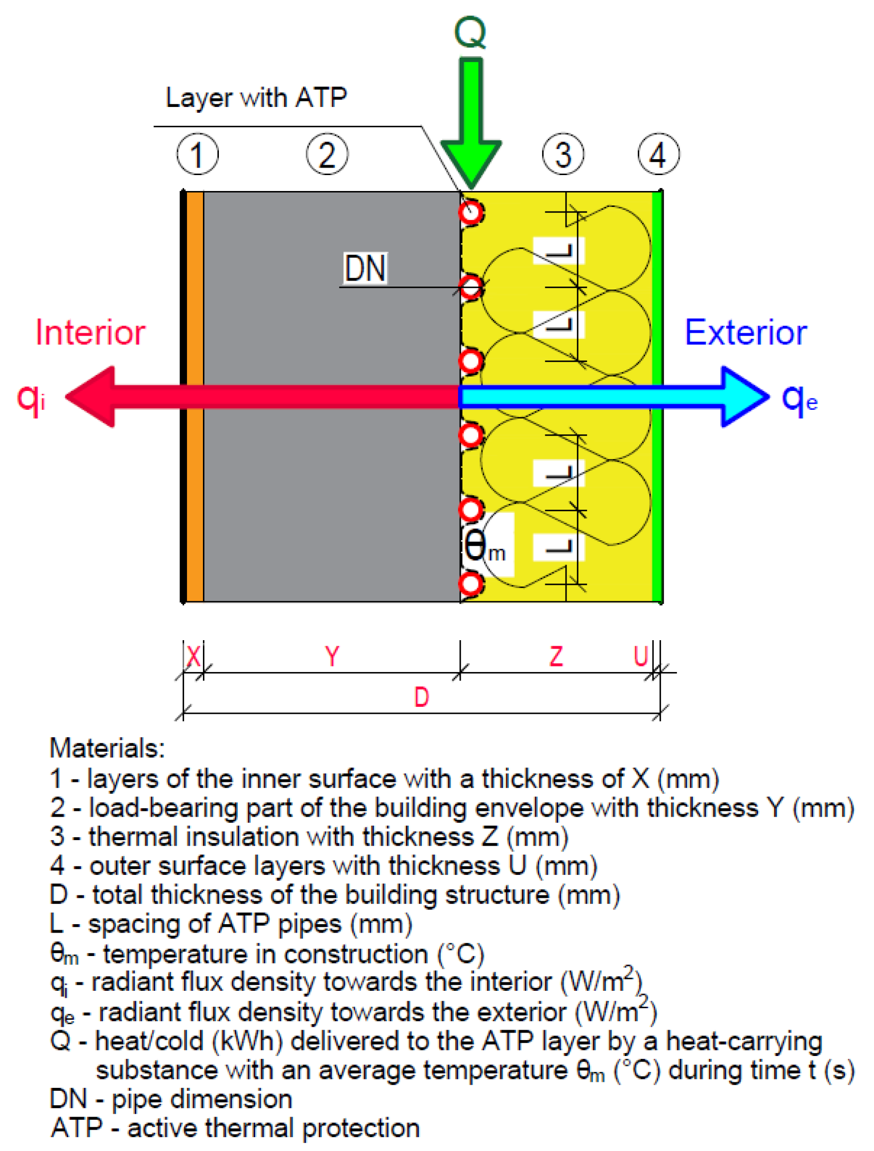
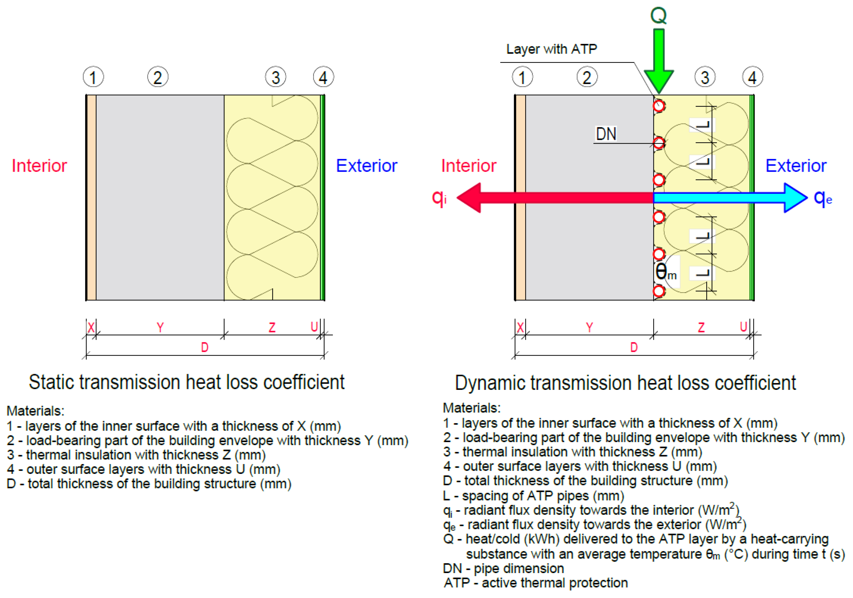
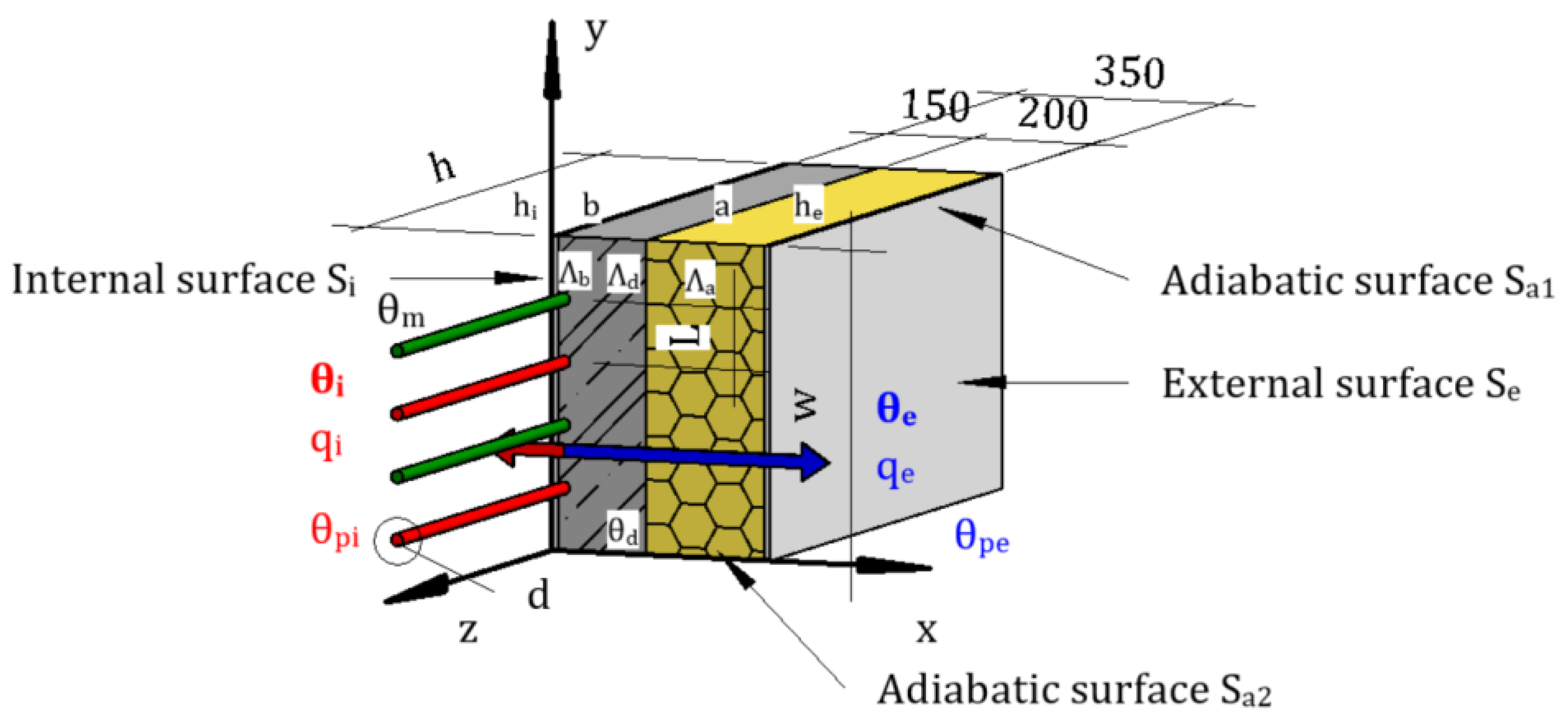
3.2.1. Calculation of Thermo-Technical Parameters of Building Structures

Figure 4, Figure 5 and Figure 6 show the mathematical–physical models for calculating the dynamic thermal resistance RDTR ((m2·K)/W), dynamic transmission heat loss coefficient UD (W/(m2·K)), dynamic insulation thickness dD (m), and mean temperature of the heat transfer medium in the ATP layer θm (°C) for the basic variants of the building envelope.
Variant 1 (Figure 4) implements ATP between the load-bearing part of the multilayer building structure and the thermal insulation. Variant 2 (Figure 5) implements ATP between the load-bearing part of the multilayer building structure and the thermal insulation, simultaneously from the exterior side of the thermal insulation for the application of heat from the unfrozen depth of the soil. Finally, variant 3 (Figure 6) implements the ATP in the reinforced concrete core of the building envelope.
For the analyzed fragment of the building envelope, it is necessary to define the boundary conditions for the application of ATP for the parametric study: the outer dimension of the ATP pipe = 10 to 20 mm, the distance between pipes = 0.10 to 0.25 m, heat transfer coefficient towards the interior = 8 W/(m2·K) (according to EN 15377-1 and CSN 730548), heat transfer coefficient towards the exterior = 15 W/(m2·K) (according to CSN 73 0548). In the simplified calculation relations, the same air temperature in front of and behind the pipe was considered in calculating the average temperature of the structure in the pipe axis and the average surface temperature in accordance with [25,26]. Therefore, the calculations are performed for an outside air temperature θe = −11 °C and an inside air temperature θi = 20 °C. The average temperature of the heat transfer medium in the ATP pipe is considered to be θm = 0 to 35 °C. The calculation was carried out based on an algorithm developed by us and simplified calculation software in Excel.
One of the energetic functions of ATP is to eliminate the thickness of static thermal insulation by means of the so-called thermal barrier (TB). When calculating the ATP energy potential of a multilayer building structure, we determine the temperatures in the individual layers—the temperature progression. From the point of view of TB application, the temperature of the layer between the thermal insulation and the load-bearing part of the building structure is the most important. This temperature can be actively influenced by the heat transfer medium supplied to the ATP heat exchange layer tubes, thus controlling the heat transfer. To determine the heat transfer through the layers in a multilayer building structure fragment, we first need to calculate the static transmission heat loss coefficient U (W/(m2·K)) and the static thermal resistance of the building structure R ((m2·K)/W). The temperature in the ATP layer determines the magnitude of the dynamic thermal resistance RDTR ((m2·K)/W), or dynamic transmission heat loss coefficient UD (W/(m2·K)), and the thickness of the dynamic thermal insulation dD (m) as equivalent to the temperature in this layer achieved at a certain thickness of static thermal insulation without the use of ATP. Elimination of the thickness of static thermal insulation means a reduction in thickness from, for example, 200 mm to 100 mm, not complete elimination. Preliminary research results indicate that static thermal insulation should not be less than 50 mm thick. To calculate the fragment’s thermal–technical properties, we used the procedure according to STN 73 0540, STN EN ISO 13790/NA/Z1, STN EN ISO 6946, and STN EN ISO 10456/AC [27,28,29,30,31].
The thermal resistance of the j-th layer of the structure is calculated using the formula [27,28,29,30,31]:
R j = d j λ j
where Rj is the thermal resistance of the j-th layer of the structure ((m2·K)/W), dj thickness of the j-th layer of the structure (m), λj coefficient of thermal conductivity of the j-th layer of the structure (W/(m·K)).
The thermal resistance of a multilayer structure is calculated using the formula [27,28,29,30,31]:
Rc = ∑Ri
R = Rsi + Rc + Rse
where R is the thermal resistance of the structure ((m2·K)/W), Rc is the total thermal resistance of the structure ((m2·K)/W), Rj is the thermal resistance of the j-th layer of the structure ((m2·K)/W), Rsi is the thermal resistance to heat transfer at the internal surface of the structure ((m2·K)/W), and Rse is the thermal resistance to heat transfer at the external surface of the structure ((m2·K)/W).
The static transmission heat loss coefficient of a multilayer structure is calculated using the formula [27,28,29,30,31]:
U = 1 R s i + R + R s e
where U is the static transmission heat loss coefficient (W/(m2·K)/), R is the thermal resistance of the structure ((m2·K)/W), Rsi is the thermal resistance to heat transfer at the internal surface of the structure ((m2·K)/W), and Rse is the thermal resistance to heat transfer at the external surface of the structure ((m2·K)/W).
The temperature in the j-th layer of the structure is calculated using the formula [27,28,29,30,31]:
θj = θi − U × (θi − θe) × (Rsi + ∑Rj)
where U is the static transmission heat loss coefficient of the structure (W/(m2·K)), Rsi is the thermal resistance to heat transfer at the internal surface of the structure ((m2·K)/W), ∑Rj is the sum of thermal resistances of the j-th layers of the structure ((m2·K)/W), θe is the outdoor design temperature in winter (°C), θi is the internal design temperature (°C), and θj is the temperature in the j-th layer of the structure (°C).
The primary input parameters entering into the calculation of static and dynamic thermal resistance are described in the mathematical–physical model in Figure 7. In addition to the parameters characterizing the static thermal resistance calculation, the heat/cool Q (kWh) delivered to the ATP at time t (s) enters the dynamic thermal resistance calculation. The latter is influenced by the mean temperature of the heat transfer medium θm (°C) and the pipe distance L (m) in the ATP layer. Thus, if we insert ATP pipes in a perimeter wall structure, in which the temperature of the heat transfer medium may vary, we can speak of dynamic thermal resistance. Dynamic thermal resistance is based on the essential relationships between static thermal resistance and the static heat transfer coefficient.

3.2.2. Basic Calculation of Large-Scale Radiant Heating

Many scientists and researchers around the world are investigating large-scale radiant systems. Significant results of their research are published, for example, in papers [32,33,34,35,36,37,38]. The ATP system’s heat exchange represents a combination of convection and radiation-based heat transfer. Both inside and outside of the building structure, heat transmission takes place. The following can be found inside the building structure [39,40,41,42,43,44]:
-
air movement because the air is warmer at higher positions and cooler in lower positions;
-
radiation results from a certain structure’s heat exchange with all other room structures.
-
There are several things outside the building structure:
-
the wind primarily causes the structure’s airflow;
-
radiation between a certain surface of a structure and the sky, as well as between the terrain and the nearby buildings.
The following relations derived by Kolmar, Liese, Kolpakov, Kalous, Cihelka for large-area radiant heating are used to calculate the heat flux from the ATP:
The average temperature of the structure in the axis of the pipes:
θ d θ i = θ m θ i · t g h m · L 2 m · L 2
where θd is the average temperature of the structure in the axis of the pipes (°C), θi is the calculated internal room temperature (°C), θm is the average heating water temperature (°C), L is the axial distance of pipes (m), and m is the coefficient characterizing the heating plate in terms of heat dissipation (m−1) [39,40,41,42,43,44].
Coefficient characterizing the heating plate in terms of heat dissipation:
m = 2 · Λ a + Λ b π 2 · λ d · d
where Λa is the thermal permeability of the layer in front of the pipes toward the interior (W/(m2·K)), Λb is the thermal permeability of the layer behind the pipes toward the exterior (W/(m2·K)), λd is the thermal conductivity of the material into which the tubes are inserted (W(/m·K)), and d is the pipe diameter (m) [39,40,41,42,43,44].
Thermal permeability of the layer in front of the pipes toward the interior:
Λ a = 1 a λ a + 1 α p
where Λa is the thermal permeability of the layer in front of the pipes toward the interior (W/(m2·K)), a is the thickness of the layer in front of the pipes (m), λa is the thermal conductivity of the material of the respective layer (W/(m·K)), and αp is the heat transfer coefficient toward the interior (W/(m2·K)) [39,40,41,42,43,44].
Thermal permeability of the layer behind the pipes toward the exterior:
Λ b = 1 b λ b + 1 α p
where Λb is the thermal permeability of the layer behind the pipes toward the exterior (W/(m2·K)), b is the thickness of the layer behind the pipes (m), λb is the thermal conductivity of the material of the respective layer (W/(m·K)), and α´p is the heat transfer coefficient toward the exterior (W/(m2·K)) [39,40,41,42,43,44].
The average surface temperature of the structure:
θ p θ i = Λ a α p · θ d θ i = Λ a α p · θ m θ i · t g h m . L 2 m . L 2
where:
Specific heat output (flow) from the structure toward the interior:
q = Λ a · θ d θ i = α p · θ p θ i
Specific heat output (flow) from the structure toward the exterior:
q = Λ b · θ d θ i = Λ b · α p Λ a · θ p θ i + Λ b · θ i θ e
where q is the specific heat output (flow) from the structure toward the interior (W/m2), q″ is the specific heat output (flow) from the structure toward the interior (W/m2), θd is the average temperature of the structure in the axis of the pipes (°C), θi is the calculated internal room temperature (°C), θm is the average heating water temperature (°C), L is the axial distance of pipes (m), m is the coefficient characterizing the heating plate in terms of heat dissipation (m−1), Λa is the thermal permeability of the layer in front of the pipes toward the interior (W/(m2·K)), λa is the thermal conductivity of the material of the respective layer (W/(m·K)), αp is the heat transfer coefficient toward the interior (W/(m2·K)), Λb is the thermal permeability of the layer behind the pipes toward the exterior (W/(m2·K)), and λb is the thermal conductivity of the material of the respective layer (W/(m·K)) [39,40,41,42,43,44].

3.2.3. Standard Calculation of Large-Area Radiant Heating Parameters

The following factors are needed to calculate the wall surface’s specific heat output q following STN EN [45,46,47,48,49] and BS EN 1264-(1-5) [50,51,52,53,54]:
-
heating pipe distance;
-
the wall layer’s thickness su and thermal conductivity λE, measured in relation to the interior and in front of the heating tubes;
-
the thermal resistance of the surface covering Rλ,B of the wall;
-
the outer diameter of the heating tubes D = da, possibly with coating D = dM, and the thermal conductivity of the heating tubes λR or coating λM;
-
the spreading layer or contact between the tubes and the heat pipe elements that are determined by the coefficient aK.
The specific heat capacity is calculated according to the equation [45,46,47,48,49,50,51,52,53,54]:
q = B × i a i m i × Δ θ H
where q is the specific heat capacity (W/m2), B is the system dependent coefficient (W/(m2·K)), and i a i m i is the power product combining the design parameters between each other [45,46,47,48,49,50,51,52,53,54]:
Δ θ H = θ V θ R ln θ V θ i θ R θ i
where ΔθH is the average temperature of the heating medium (°C), θV is the supply temperature of the heating medium (°C), θR is the return temperature of the heating medium (°C), and θi is the nominal indoor temperature of the room (°C).
The specific heat capacity is proportional to (ΔθH)n, as exponent n has values according to theoretical results confirmed by experiments: 1.0 < n < 1.01; within the limits of sufficient precision, a value is used, n = 1 [45,46,47,48,49,50,51,52,53,54].
In STN EN 1264, there are different types of compositions of structures. However, the most relevant standard structure type for the structure we are analyzing is B, Figure 8.
For a type B system, the specific heat capacity q is calculated according to the relation [45,46,47,48,49,50,51,52,53,54]:
q = B × a B × a T m T   × a u m u × a WL × a k × Δ θ H
where q is the specific heat capacity (W/m2), B is the system-dependent coefficient (W/(m2·K)), where applies [45,46,47,48,49,50,51,52,53,54]:
a B = 1 1 + B × a u × a T m T × a W L × a K × R λ , B × f L
herewith [45,46,47,48,49,50,51,52,53,54]:
F ( T ) = 1 + 0.44   L
where aB is the covering coefficient (-); aT is the tube spacing coefficient (-), Table 1; aT = f (su/ λ E ); λ E is the thermal conductivity of the spreading layer (W/(m·K)); su is the thickness of the spreading layer over the tubes (m); mi is the exponents to calculate the characteristic curves (mT, mu) (-), where holds [45,46,47,48,49,50,51,52,53,54]:
m T = 1 L 0.075         suits   when   0.050   m     L     0.375   m
mu = 100 (0.045 − su) suits when su ≥ 0.010 m
where L is the spacing of the heating tubes (m); su is the thickness of the spreading layer above the tubes (m).
If the pipe spacing is L > 0.375 m, the specific power is calculated from the formula [45,46,47,48,49,50,51,52,53,54]:
q = q 0.375   · 0.375 L
where q is the specific heat capacity (W/m2), q0.375 is the specific heat capacity (W/m2) calculated at pipe spacing L = 0.375 m, where [45,46,47,48,49,50,51,52,53,54,55,56,57,58]:
a u = 1 α + s u , 0 λ u , 0 1 α + s u λ E
where au is the covering factor (-); α = 10.8 W/(m2·K); λ u , 0 = 1 W/(m2·K); s u , 0 = 0.045 m; aK is the correction coefficient of coupling in compliance, Table 2; ak = f (T); aWL is the thermal conductivity coefficient, Table 3; aWL = f (KWL, L, D); ΔθH is the average temperature of the heating substance (°C), Formula (14) [35,36,37,38,39,59,60,61,62,63].
Tables for KWL = 0.1; 0.2; 0.3; 0.4; 0.5 and above; see STN EN 1264-2, where KWL is the coefficient of the heat conducting element for type B (-) systems [45,46,47,48,49,50,51,52,53,54]:
K WL = s W L × λ W L + b u × s u × λ E 0.125
where bu = f (L)Table 4; sWL x λ W L = product of thickness and thermal conductivity of the heat conducting element; su x λ E = product of thickness and thermal conductivity of the spreading layer.

3.2.4. Calculation of the Heat, Energy, and CO2 Emission Demand When Using ATP

We calculate the heat demand, energy demand, and CO2 emissions using the following procedure [40].
Annual heat demand for heating (kWh/a):
Q heat = 277,778 × 24 × 3600 × Ɛ × Φ H L × θ i θ e , p r θ i θ e × d × 10 6
where Qheat is the annual heat demand for heating (kWh/a); ΦHL is projected to heat input calculated with a surcharge for heat losses during distribution (kW); Ɛ is the coefficient of non-simultaneity of operation, type of regulation, and heating mode (-); Ɛ = 0.8 central regulation, Ɛ = 0.75 central zone regulation, Ɛ = 0.7 central regulation and individual regulation, θi is internal calculation temperature (°C); θe is external calculation temperature (°C); θe,pr is the average outdoor air temperature in the heating season (°C); d is number of days in the heating season (-) [55].
Total annual energy demand (kWh/a):
E = Q η c = Q h e a t η c , h e a t = E h e a t
where Q is total annual heat demand (kWh/a); Qheat is annual heat demand for heating (kWh/a); η c is heat production and distribution efficiency factors (heat source (1), distribution (2), heat transfer station (3)) (-); η 1 = 0.75 up to 0.92—primary sources; η 2 = 0.94—primary distribution systems—warm water; η 2 = 0.93—primary distribution systems—hot water; η 2 = 0.95—secondary distributions; η 3 = 0.99—heat transfer station; [55].
η c = η 1 × η 2 × η 3
Equation (23) is used to calculate the heat demand Qheat (kWh/a) delivered to the ATP as the dynamic thermal resistance changes with the mean temperature of the heat transfer medium θm (°C) and the corresponding heat loss ΦHL (kW) from the ATP layer to the exterior. Equation (25) is used to calculate the overall efficiency of the heating system and to determine the energy delivered to the ATP. Fuel demand, primary energy, and CO2 emissions can be determined based on the type of energy carrier.
Annual fuel requirement (m3/a, kg/a):
B r = E H u = E h e a t H u
where E is total annual energy demand (kWh/a); Eheat is annual energy needed for heating (kWh/a); Hu is the calorific value of fuel (MJ/m3, MJ/kg) [55].
Primary energy calculation:
q h e a t = E h e a t S × f PE
where qheat is the specific energy need for heating (kWh/(m2·a)), Eheat is the annual energy needed for heating (kWh/a), S is the specific surface area of the building (total heated area calculated from the external dimensions of the building) (m2), fPE is the factor of primary energy (kWh/(m2·a)) [55].
Calculation of CO2 emissions (kg/ (m2·a)):
EMCO2 = qheat × fCO2
where EMCO2 is CO2 emissions (kg/(m2·a)); qheat is the specific energy need for heating (kWh/(m2·a)); and fCO2 is the CO2 emission factor (kg/(m2·a)) [55].

4. Results

Based on the synthesis and analysis of scientific and practical knowledge obtained from published works of researchers and experts in the field, transforming these data, we developed a mathematical–physical model of the building envelope fragment for parametric study and upcoming computer simulation (Figure 4). The parametric study research was carried out on the perimeter wall of the experimental house EB2020, the composition of which can be seen in Figure 9. The layer towards the interior from the ATP is made of thermally insulated aerated concrete blocks with a thickness of 375 mm. The thickness of the thermal insulation is 100 mm. In this chapter, we present the results obtained so far from the parametric study of ATP [56,57].

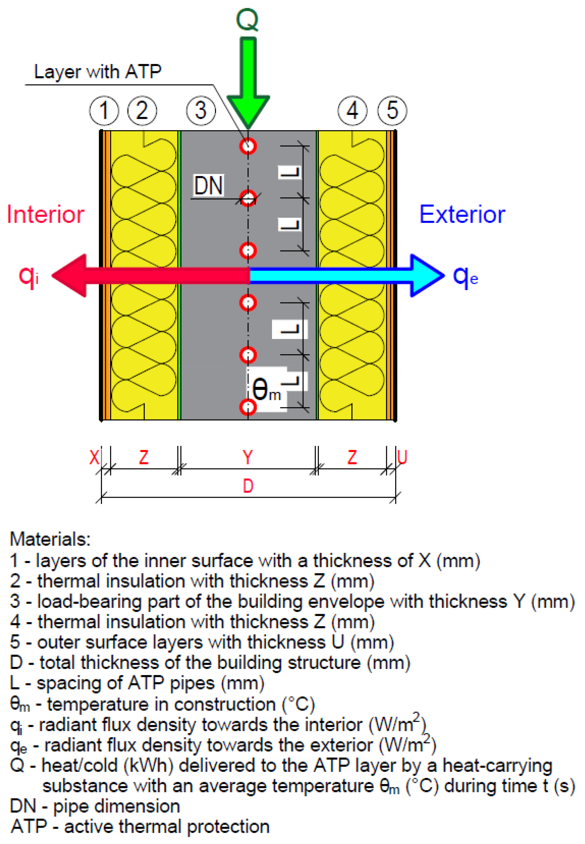
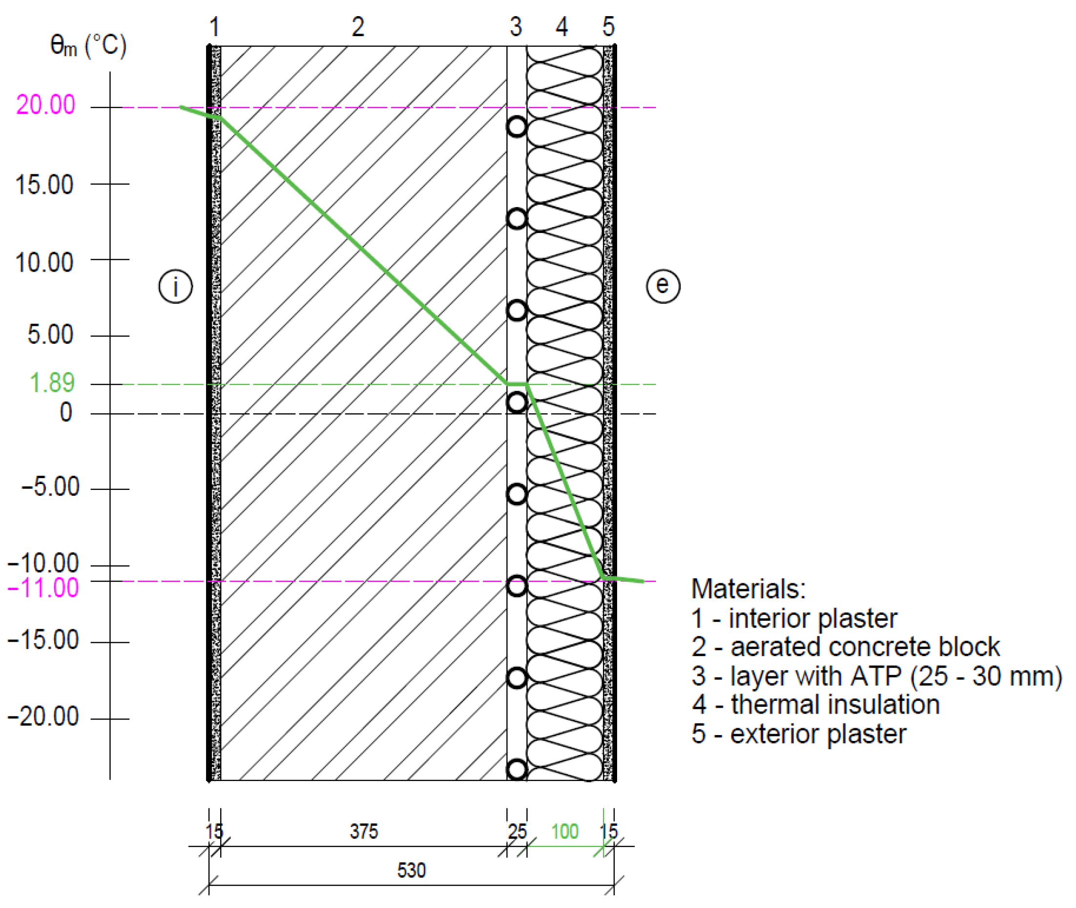
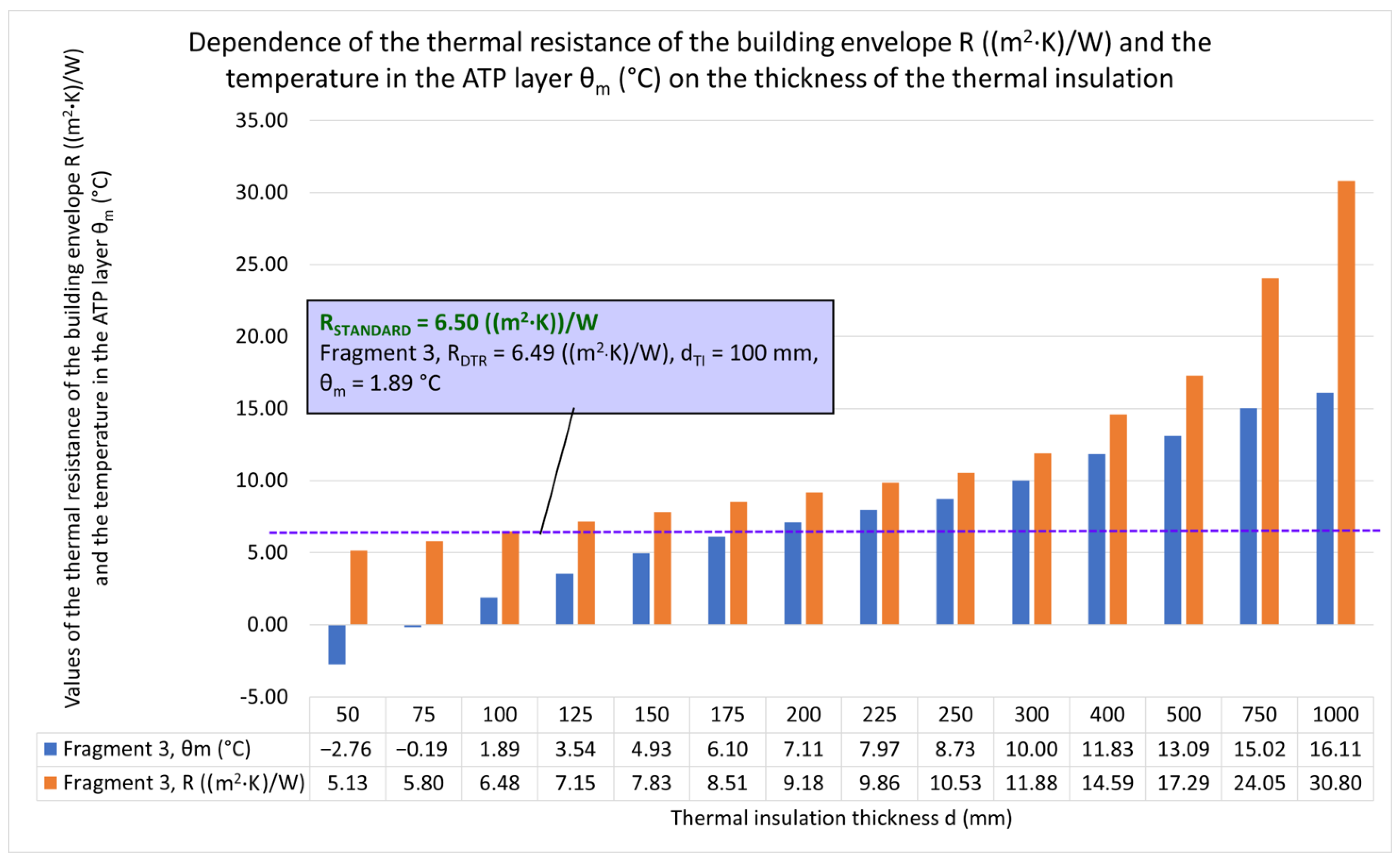
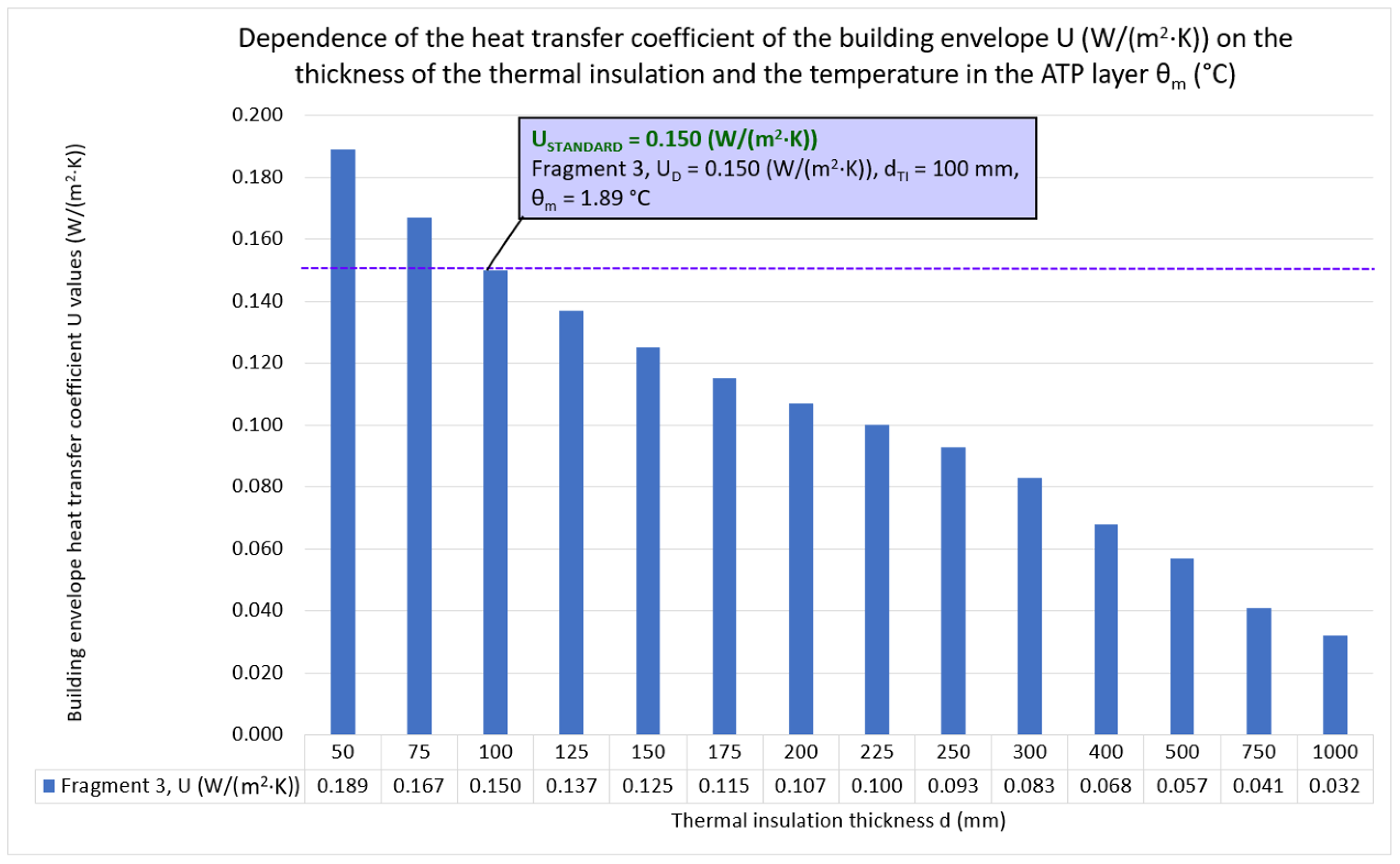
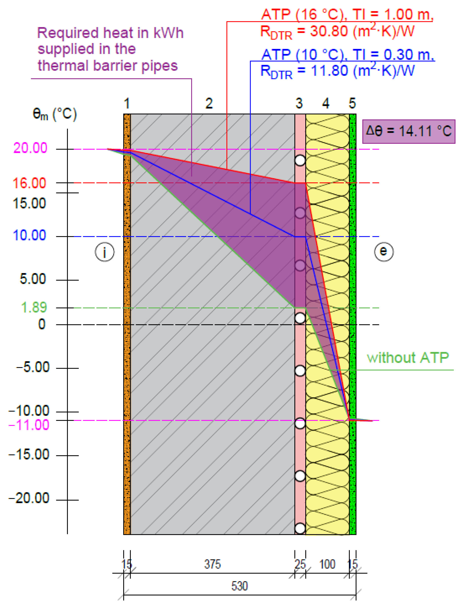
4.1. Results of a Parametric Study of ATP in the Energy Function of the Thermal Barrier

An important role of ATP, besides its multifunctional energy character, is the elimination of static thermal insulation. Employing the heat/coolant supplied by the heat transfer medium to the tubes of the heat exchange surface of the ATP, the heat/cool transfer from the interior to the exterior and vice versa is regulated in the building structure.
In the ATP location layer, the internal temperature is θm = 1.89 °C, and RDTR = 6.48 ((m2·K)/W), as shown in Figure 9. The graph in Figure 10 illustrates how the mean temperature of the heat transfer medium inside the ATP pipes, which make up the heat transfer layer in the building structure, and the thickness of the static/dynamic thermal insulation affect the dynamic thermal resistance. Similar to Figure 10, Figure 11 depicts the relationship between the dynamic transmission heat loss coefficient UD (W/(m2·K)) and temperature. Figure 12 shows isotherms illustrating the temperature histories in a building structure with 100 mm of static thermal insulation without ATP application (green line) and with ATP application. As the temperature of the heat transfer medium increases at the ATP level, the dynamic thermal resistance of this building envelope increases. For example, if the internal temperature in the layer is θm = 10 °C, the thermal resistance is RDTR =11.8 ((m2·K)/W) with a dynamic thermal insulation of 300 mm (blue line). For a temperature θm = 16.11 °C, the thermal resistance RDTR = 30.80 ((m2·K)/W) for a dynamic thermal insulation thickness of 1000 mm (red line). The heat delivered in the form of a heat transfer medium to this layer increases its temperature from 1.89 °C to 16 °C, i.e., ∆θ = 14.11 °C. The figure also illustrates the proportion of heat delivered by the thermal barrier (purple area) [56,57].

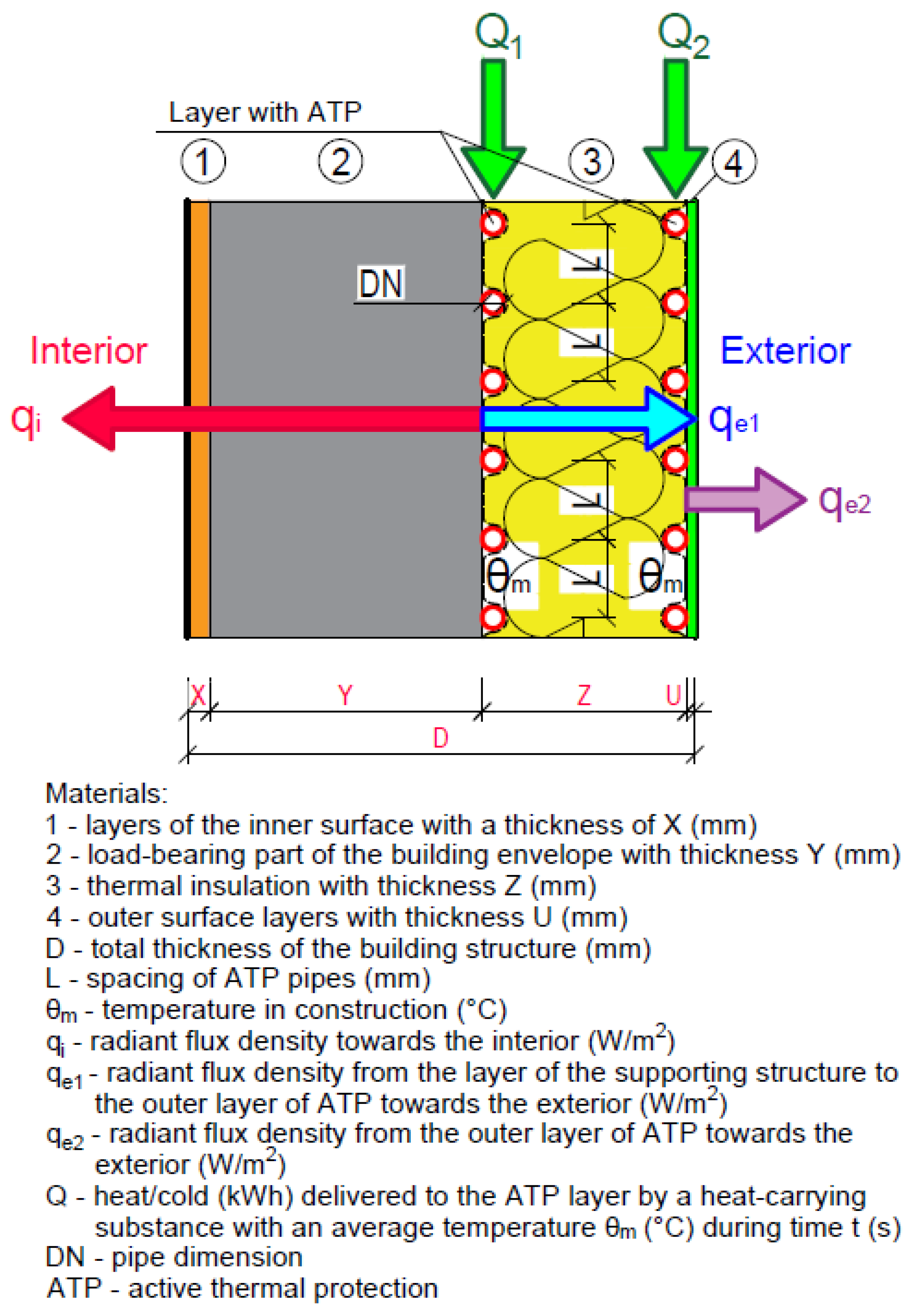
4.2. Results of a Parametric Study of ATP in the Energy Function of Radiant Heating

ATP in multilayer building structures with appropriately selected materials of individual layers, especially static/load-bearing layers and inner surface layers, can have the function of large-scale low-temperature heating and high-temperature cooling, in addition to the energy function of TB. The heat/cool accumulation in the static/load-bearing layer in the TABS function can also be of great importance in terms of energy efficiency. We have developed an algorithm and simplified calculation software in Excel for a parametric study of heat fluxes for radiant heating/cooling. The results are presented in Table 5, Table 6 and Table 7.
The results of the calculation of the characteristic data for the variant solutions of direct radiant heating, semi-accumulation heating (TABS system), and accumulation heating with the application of ATP are given for the temperature of the heating medium: 25 °C (Table 5), 30 °C (Table 6), and 35 °C (Table 7).
From the analysis of the calculated characteristic data, it is evident that when the envelope is designed with a layer of thermal insulating aerated concrete blocks towards the interior from the ATP, the heat flux with direct heating will be significantly higher, more than 92%, compared to the variant with semi-accumulation (TABS) and the variant 96% with accumulation (ATP) heating/cooling.
For example, an average temperature of the heat transfer medium of 30 °C, the heating heat flux to the interior with a temperature of 20 °C, an exterior temperature of −11 °C, and an axial distance of the pipes of 150 mm will be almost 55 W/m2 for direct heating, 4.5 W/m2 for semi-accumulation heating (TABS), and only 2.3 W/m2 for accumulation heating (ATP) (Table 6).
A graphical representation of the composition of the building structure is given in the following figures:
-
classic large-area radiant heating—Figure 13,
-
thermally activated building systems (TABS)—Figure 14,
-
active thermal protection (ATP)—Figure 15.
The role of the ATP for this building envelope system is restricted to the thermal barrier and heat/cool accumulation functions due to the layer load-bearing wall’s strong thermal resistance. For instance, Table 6 shows that the accumulated energy for semi-accumulation heating (TABS) and accumulation heating (ATP) equals roughly 78.5% and 71.3% of the total delivered energy, respectively, at a mean temperature of the heat transfer medium of 30 °C. Based on the analysis of the characterization data obtained from the parametric study, it can be concluded that heating/cooling using ATP is inefficient and energy intensive in the considered envelope building design of the experimental house EB2020. On the other hand, due to the high energy accumulation, this envelope design with ATP in the TB function represents a stable dynamic thermal insulation exploiting the self-regulating effect.

5. Discussion

By synthesizing, analyzing, and inducing analogous forms of the results of previous research into recommendations for the design of individual energy functions of ATP for building envelopes:
  • ▪ we present the heat fluxes to the interior/exterior when changing the material of the layers towards the interior from the ATP;
  • ▪ determine the conditions for the effective use of active thermal protection; and
  • ▪ describe possible options for the development of building structures with integrated energy-active elements.

5.1. Changing the Material of the Load-Bearing Part of a Fragment of the Building’s Perimeter Wall

The parametric study results indicate that the building envelope of the experimental house EB2020 made of aerated concrete blocks with active thermal protection (ATP) is advantageous to be used only in the energy function of thermal barrier and heat/cold accumulation. It can be partially used in the passive wall cooling function. ATP on the experimental house in question can also be used as wall heating. Still, the operation would be several times more energy-intensive compared to direct wall heating and underfloor heating. By changing the material of the load-bearing part of the building envelope wall fragment in the project and planning process, it is possible to design and plan the energy function of the building structure with energy-active elements. Based on the parametric study, suppose we replace the thermal insulating aerated concrete blocks with reinforced concrete panels or masonry made of solid burnt bricks. In that case, we find that these two constructions can be applied in addition to the function of the thermal barrier and also in the function of wall heating/cooling. The function of heat/cool accumulation also becomes non-negligible.
Table 8 and Table 9 show characteristic data for direct heating, semi-accumulation heating (TABS), and accumulation heating (ATP) for the static/supporting part of the building envelope made of brick and reinforced concrete masonry, a mean temperature of the heat transfer medium of 30 °C, an axial distance of the ATP pipes of 150 mm, an internal temperature of 20 °C, and an external temperature of −11 °C. As the thermal conductivity of the static/load-bearing part of the envelope increases, the heat flux for heating/cooling increases. For the same boundary conditions, the heat flux for heating for the EB2020 experimental house envelope made of aerated concrete blocks is 2.31 W/m2 (Table 6); for brick masonry, 12.167 W/m2 (Table 8); and for reinforced concrete masonry, 23.174 W/m2 (Table 9).
The ratio of losses to the exterior to the total energy delivered to the ATP compared to direct-fired heating is 16% for the EB2020 experimental house envelope made of aerated concrete blocks (Table 6), 5.4% for brick masonry (Table 7), and 3.3% for reinforced concrete masonry (Table 8).
The energy accumulation delivered to the ATP is 71.3% for the EB2020 experimental house envelope made of aerated concrete blocks (Table 6), 60.57% for brick masonry (Table 7), and 44.81% for reinforced concrete masonry (Table 8).
For a given envelope design of the experimental house EB2020, the design considered in the parametric study, due to the composition of the layers towards the interior and exterior and the different temperatures (interior +20 °C, exterior −11 °C), the heat flux from the ATP layer to the interior and exterior is delivered depending on the thermal resistance of the layers and the mean temperature in the ATP, e.g., 30 °C. The heat that makes up the difference between the total heat delivered to the ATP and the heat transferred to the interior and exterior in the sense of the law of conservation of energy is the stored heat in the ATP layer. Considering the given thermo-technical properties of the investigated structure, the accumulated heat in the ATP amounts to 71.3% of the total heat delivered to the ATP. Therefore, the total heat delivered to the ATP is always the same for the different designs compared (direct heating, semi-accumulation, and accumulation heating).

5.2. Analysis, Synthesis, and Transformation of Outputs from Parametric Study and into Results and Recommendations for Science and Practice in the Field of ATP Application

Due to the fact that the pipes in ATP are shifted towards the exterior compared to large-scale radiant wall heating, the heat losses from ATP to the exterior are higher. Based on a parametric study, setting lower inlet temperatures of the working substance to the ATP system is recommended. It is assumed that the higher the set inlet temperature to the ATP, the lower the heat consumption of the supplementary heating system, but the total specific heat delivered is significantly higher. For the envelope of the experimental house EB2020, the heat flux to the exterior is 13.135 W/m2 at a mean temperature of 25 °C, 14.957 W/m2 at 30 °C, and 16.78 W/m2 at 35 °C. Therefore, it is inefficient to heat the building using active thermal protection with such a construction. The operation is particularly relevant if renewable energy sources or waste heat are used.
The application of ATP in the function of wall heating and cooling is of practical importance only in building constructions that have a high thermal conductivity on the interior side in front of the ATP tubes, i.e., a suitable volumetric mass and heat capacity. For a given building envelope construction in the experimental house EB2020 made of thermal insulating aerated concrete blocks, heating with ATP is very limited and economically inefficient. Therefore, covering the heat load through non-transparent structures with wall cooling is practically the only possible method. For the use of ATP as wall heating/cooling, it is recommended to design structures with suitable heat/cool accumulation, for example, reinforced concrete with a suitable thickness of thermal insulation from the exterior. Characteristic data for direct heating, semi-accumulation heating (TABS system), and accumulation heating (ATP system) for brickwork and reinforced concrete masonry variants are given in Table 8 and Table 9.
For wall heating and cooling purposes, buildings with significant thermal resistance in front of the ATP tubes should not be used. The current ATP system on the market cannot offer year-round thermal comfort at the typical temperature gradients of low-temperature heating and high-temperature cooling, as shown in Figure 3 and Figure 6. The tubes are installed in a reinforced concrete structure that is provided with thermal insulation on the interior and exterior sides. The heating function operates energy- and cost-inefficiently at higher temperature gradients. The heating system must be designed for such designs. Only the functionalities of thermal barrier and heat/cool accumulation can be used with this system.
For building constructions that have high thermal resistance towards the interior in front of the ATP tubes, reducing the axial distance of the tubes and, at the same time, increasing their DN in the wall heating function will not significantly increase the surface temperature on the interior side, nor the heat flux to the interior [56,57].

5.3. Synthesis and Induction of Analogous Forms of Previous Research Results into Recommendations for the Development of Building Envelopes with Energy-Active Elements

In article [58], we analyzed the variant energy functions of building envelopes with ATP. The nature of the dynamic thermal barrier, low-temperature heating/high-temperature cooling, and heat/cooling storage applied to building structures with integrated energy-active elements predestine this system also for use in industrial buildings, commercial premises, and other amenity buildings, where renewable energy sources and waste heat, e.g., from refrigeration and freezing equipment, can be used in addition to traditional heat sources. The ability to employ air as a heat transfer medium in the ATP, depicted in Figure 16, supports the diversity of application in all sorts of buildings or spaces. A plastic (metal) air conditioning duct with a circular cross-section and a diameter of 50 to 100 mm can be inserted into a thermal insulation board to create the air heat carrier panels.
ATP can also be applied to the exterior of building envelopes. The integrated active surface can have an energy register function capturing solar or ambient energy. In the patent [59] and utility model [60], we propose using panels with integrated energy-active elements as a standard contact insulation system. The active surface—a register formed by tubes for a liquid or gaseous heat carrier—is characteristic of the external surface. These thermally active panels can be combined with renewable heat sources or waste heat/cooling, as shown in Figure 17.
Another choice for developing a small insulation system is the integration of thermal insulation panels with active heat transfer control employing ATP with an integrated active surface (TB, heating/cooling, and heat storage), as illustrated in Figure 18. Insulation panels with ATP (WATER as a heat carrier or AIR with an extra absorber function on the exterior to collect ambient energy) fall under this category. This decreases the number of operations required for the building construction process and the energy system’s implementation while extending the various functionalities of the construction and contact insulation systems. The unified façade system can still be installed with the same ease and technology process as before.
Research on combined building–energy systems is related to several technical fields in which the results from various scientific and professional publications need to be correlated. Therefore, we list some relevant publications on which we base our research [63,64,65,66,67,68,69,70].

6. Conclusions

In conclusion, we can responsibly state, as already mentioned above, that the results of the study indicate that the external shell of the construction object of the experimental house made of aerated concrete blocks with active thermal protection (ATP) is advantageous to use only in the case of the energy function of the thermal barrier and heat/cold accumulation. It can partially be used as a passive wall-cooling function. ATP on the subject experimental house can also be used as wall heating. Still, the operation would be more energy-demanding than direct wall heating and floor heating. Suppose the original load-bearing building material (heat-insulating aerated concrete blocks) was replaced by reinforced concrete panels or masonry made of solid burnt bricks. In that case, we conclude that these two structures can be used as a thermal barrier and a wall heating/cooling function. The heat/cold storage function also becomes significant.
Another important finding is that in the perimeter construction, heat losses from ATP to the exterior are also higher because the pipes are moved towards the exterior in contrast to large-area radiant wall heating. Therefore, it is recommended to set lower inlet temperatures of the working substance to the ATP system. It is assumed that the higher the set inlet temperature of the system, the lower the heat consumption of the supplementary heating system. However, the total delivered specific heat is significantly higher. Therefore, the application of ATP in heating and cooling walls is of practical importance only in constructions with high thermal conductivity inside and in front of the ATP tubes.
The nature of the dynamic thermal barrier, low-temperature heating/high-temperature cooling, and heat/cold accumulation applied to building structures with integrated energetically active elements predetermines this system for use in other civil engineering buildings than just residential buildings, i.e., in buildings where, in addition to traditional heat sources, renewable energy sources and waste heat from installed technology can also be used.

7. Patents

Based on our research in the field of combined building–energy systems and experimental measurements, the results have been processed into one European patent [59] and three utility models [60,61,62].

Author Contributions

Conceptualization, V.M., D.K. (Daniel Kalús), D.K. (Daniela Koudelková), M.K., Z.S., M.S., R.I., P.Š. and P.J.; methodology, V.M., D.K. (Daniel Kalús), D.K. (Daniela Koudelková), M.K., Z.S., M.S., R.I., P.Š. and P.J.; validation, V.M., D.K. (Daniel Kalús), D.K. (Daniela Koudelková), M.K., Z.S., M.S., R.I., P.Š. and P.J.; formal analysis, V.M., D.K. (Daniel Kalús), D.K. (Daniela Koudelková), M.K., Z.S., M.S., R.I., P.Š. and P.J.; investigation V.M., D.K. (Daniel Kalús), D.K. (Daniela Koudelková), M.K., Z.S., M.S., R.I., P.Š. and P.J.; resources, V.M., D.K. (Daniel Kalús), D.K. (Daniela Koudelková), M.K., Z.S., M.S., R.I., J.Č., P.Š. and P.J.; data curation, V.M., D.K. (Daniel Kalús), D.K. (Daniela Koudelková), M.K., Z.S., M.S., R.I., P.Š. and P.J.; writing—original draft preparation, V.M., D.K. (Daniel Kalús), D.K. (Daniela Koudelková), M.K., Z.S., M.S., R.I., P.Š. and P.J.; writing—review and editing, V.M., D.K. (Daniel Kalús), D.K. (Daniela Koudelková), M.K., Z.S., M.S., R.I., P.Š. and P.J. All authors have read and agreed to the published version of the manuscript.

Funding

The research was supported by the private company EHBconsulting, s.r.o., Ružová 765/48, 949 01 Nitra, Slovakia.

Institutional Review Board Statement

Not applicable.

Informed Consent Statement

Not applicable.

Data Availability Statement

Not applicable.

Acknowledgments

This research is supported by the Ministry of Education, Science, Research and Sport of the Slovak Republic through the grant VEGA 1/0229/21, building physics fundamentals of a nearly zero-energy building related to its environmental aspects and through the grant VEGA 1/0118/23, and variant technical solutions for heat/cooling sources and energy systems in buildings by means of building structures with integrated energy-active elements using RES versus fossil fuels in the context of energy security and self-sufficiency of buildings in the EU.

Conflicts of Interest

The authors declare no conflict of interest.

Nomenclature

Abbreviations
ATP active thermal protection
BIPV/TBuilding-Integrated Photovoltaic/Thermal system
CBEScombined building-energy systems
DHWdomestic hot water
DTRDynamic Thermal Resistance
EAIWinsulating air insulation wall
Eq.Equation
ENEuropean Standard
EPEuropean patent
EPSExpanded polystyrene
ESREnergy (Solar) Roof
FEFE code ABAQUS supported by the new SVC control
system implemented in FORTRAN simulation software on real operating conditions
GHEGround Heat Exchanger
GHSground heat storage
HVACHeating, Ventilation, and Air Conditioning
IEAEIntegrated Energy-Active Elements
ISOInternational Organization for Standardization
LCClife cycle cost
PCMPhase Change Materials
RESrenewable energy sources
STNSlovak Technical Standard
TABSthermally active building system
TBthermal barrier
TIThermal insulation
UMUtility model
WIHPwall implanted heat pipe
WRAwall and roof absorbers
Symbols
a tickness of the layer in front of the pipes (m)
aB the covering coefficient (-)
aK connection correction factor (-)
aT tube spacing coefficient (-)
au coverage factor (-)
aWL coefficient for thermal conductivity (-)
B system dependent coefficient (W/(m2·K))
D diameter (m)
dconstruction thickness (mm)
da outer diameter of the heating pipes (m)
dj thickness of the j-th layer of the structure (m)
dM outer diameter of coated heating pipes (m)
dDinsulation thickness (m)
DNpipe dimension (mm)
e exterior
E total annual energy demand (kWh/a)
Eheat annual energy need for heating (kWh/a)
EM CO2 emission production (kg/a)
EMCO2 CO2 emissions (kg/(m2. a))
fCO2 CO2 emission factor (kg/(m2. a))
fPE factor of primary energy (kWh/(m2. year))
Hu the calorific value of fuel (MJ/m3, MJ/kg)
i interior
Kcoefficient of the heat-conducting element for B-type systems (-)
KWLthe coefficient of the heat conducting element for type B (-)
Laxial distance of pipes (m)
mcoefficient characterizing the heating plate in terms of heat dissipation (m−1)
mi the exponents to calculate the characteristic curves (mT, mu) (-)
Q the heat/cool delivered to the ATP (kWh)
Qheatannual heat demand for heating (kWh/a)
qspecific heat output (flow) from the structure toward the interior (W/m2)
q″specific heat output (flow) from the structure toward the interior (W/m2)
qe radiant flux density towards the exterior (W/m2)
qi radiant flux density towards the interior (W/m2)
q0.375specific heat output calculated at pipe spacing L = 0.375 m (W/m2)
qheat specific energy need for heating (kWh/(m2. a))
R thermal resistance of the structure ((m2·K)/W)
RCtotal thermal resistance of the structure ((m2·K)/W)
RDTR dynamic thermal resistance ((m2·K)/W)
Rj thermal resistance of the j-th layer of the structure ((m2·K)/W)
Rse thermal resistance to heat transfer at the external surface of the structure ((m2·K)/W)
Rsi thermal resistance to heat transfer at the internal surface of the structure ((m2·K)/W)
Rλ,B thermal resistance of the wall covering ((m2·K)/W)
S the specific surface area of the building (total heated area calculated from the external dimensions of the building) (m2)
su the thickness of the spreading layer above the pipes (m)
Ustatic transmission heat loss coefficient (W/(m2·K))
UD dynamic transmission heat loss coefficient (W/(m2·K))
Ɛ coefficient of non-simultaneity of operation, type of regulation and heating mode (-)
ηcheat production and distribution efficiency factors, distribution, heat transfer station (-)
θe outside air temperature (°C)
θi inside air temperature (°C)
θj temperature in the j-th layer of the structure (°C)
θdaverage temperature of the structure in the axis of the pipes (°C)
θe,praverage outdoor air temperature in the heating season (°C)
θm temperature in construction (°C)
θR return temperature of the heating medium (°C)
θV supply temperature of the heating medium (°C)
Δθ temperature difference (°C)
ΔθH average temperature of the heating medium (°C)
αp heat transfer coefficient toward the interior (W/(m2·K))
α′pheat transfer coefficient toward exterior (W/(m2·K))
ΦHLprojected to heat input calculated with a surcharge for heat losses during distribution (kW)
λa thermal conductivity of the material of the respective layer (W/(m·K))
λbthermal conductivity of the material of the respective layer (W/(m·K))
λj coefficient of thermal conductivity of the j-th layer of the structure (W/(m·K))
λd thermal conductivity of the material into which the tubes are inserted (W/( m·K))
λE thermal conductivity of the spreading layer (W/( m·K))
λM thermal conductivity of the covering layer (W/(m·K))
λR thermal conductivity of the heating tubes (W/(m·K))
∑Rj sum of thermal resistances of the j-th layers of the structure ((m2·K)/W)
i ( a i m i ) power product combining design parameters
sWL x λWL the product of the thickness and the thermal conductivity of the thermally conductive element
su x λE the product of the thickness and thermal conductivity of the spreading layer
athickness of the layer in front of the pipes (m)
bthickness of the layer behind the pipes (m)
Λathermal permeability of the layer in front of the pipes toward the interior (W/(m2·K))
Λbthermal permeability of the layer behind the pipes toward the exterior (W/(m2·K))
θm average heating water temperature (°C)

References

  1. Kalús, D.; Janík, P.; Kubica, M. Experimental house EB2020–Research and experimental measurements of an energy roof. Energy Build. 2021, 248, 111172. [Google Scholar] [CrossRef]
  2. Kalús, D.; Janík, P.; Koudelková, D.; Mučková, V.; Sokol, M. Contribution to research on ground heat storages as part of building energy systems using RES. Energy Build. 2022, 267, 112125. [Google Scholar] [CrossRef]
  3. ®Isomax–Terrasol Building Technologies. Successor to Isomax–Solinterra. Available online: https://www.solinterra.si/en/about-solinterra.html (accessed on 27 March 2023).
  4. Krajčík, M.; Šikula, O. The possibilities and limitations of using radiant wall cooling in new and retrofitted existing buildings. Appl. Therm. Eng. 2020, 164, 114490. [Google Scholar] [CrossRef]
  5. Krajčík, M.; Arıcı, M.; Šikula, O.; Šimko, M. Review of water-based wall systems: Heating, cooling, and thermal barriers. Energy Build. 2021, 253, 111476. [Google Scholar] [CrossRef]
  6. Krajčík, M.; Šimko, M.; Šikula, O.; Szabó, D.; Petráš, D. Thermal performance of a radiant wall heating and cooling system with pipes attached to thermally insulating bricks. Energy Build. 2021, 246, 111122. [Google Scholar] [CrossRef]
  7. Junasová, B.; Krajčík, M.; Šikula, O.; Arıcı, M.; Šimko, M. Adapting the construction of radiant heating and cooling systems for building retrofit. Energy Build. 2022, 268, 112228. [Google Scholar] [CrossRef]
  8. Šimko, M.; Petráš, D.; Krajčík, M.; Szabó, D. Testing of a Radiant Wall Cooling System with Pipes Coupled to Aerated Blocks. Period. Polytech. Mech. Eng. 2022, 66, 59–66. [Google Scholar] [CrossRef]
  9. Krecké, E.; Ulbrich, R.; Radlak, G. Connection of Solar and Near-Surface Geothermal Energy in Isomax Technology. In Proceedings of CESB 07 PRAGUE Conference. 2007; pp. 622–628. Available online: https://www.yumpu.com/en/document/read/4706674/connection-of-solar-and-near-surface-geothermal-energy-in-isomax- (accessed on 15 March 2023).
  10. Krzaczek, M.; Kowalczuk, Z. Thermal Barrier as a technique of indirect heating and cooling for residential buildings. Energy Build. 2011, 43, 823–837. [Google Scholar] [CrossRef]
  11. Zhang, Z.; Sun, Z.; Duan, C. A new type of passive solar energy utilization technology-the wall implanted with heat pipes. Energy Build. 2014, 84, 111–116. [Google Scholar] [CrossRef]
  12. Park, S.H.; Chung, W.J.; Yeo, M.S.; Kim, K.W. Evaluation of the thermal performance of a Thermally Activated Building System (TABS) according to the thermal load in a residential building. Energy Build. 2014, 73, 69–82. [Google Scholar] [CrossRef]
  13. Doležel, M. Alternative way of thermal protection by thermal barrier. Adv. Mater. Res. 2014, 899, 107–111. [Google Scholar] [CrossRef]
  14. Stojanović, B.V.; Janevski, J.N.; Mitković, P.B.; Stojanović, M.B.; Ignjatović, M.G. Thermally activated building systems in context of increasing building energy efficiency. Therm. Sci. 2014, 18, 1011–1018. [Google Scholar] [CrossRef]
  15. Babiak, J.; Vagiannis, G. Thermally Activated Building System (TABS): Efficient Cooling and Heating of Commercial Buildings. In Congreso, Climamed; 2015; Available online: https://www.researchgate.net/profile/Georgios-Vagiannis/publication/281968993_Thermally_Activated_Building_System_TABS_Efficient_cooling_and_heating_of_commercial_buildings/links/55fffa8908aeafc8ac8bb490/Thermally-Activated-Building-System-TABS-Efficient-cooling-and-heating-of-commercial-buildings.pdf (accessed on 15 March 2023).
  16. Li, A.; Xu, X.; Sun, Y. A study on pipe-embedded wall integrated with ground source-coupled heat exchanger for enhanced building energy efficiency in diverse climate regions. Energy Build. 2016, 121, 139–151. [Google Scholar] [CrossRef]
  17. Kisilewicz, T.; Fedorczak-Cisak, M.; Barkanyi, T. Active thermal insulation as an element limiting heat loss through external walls. Energy Build. 2019, 205, 109541. [Google Scholar] [CrossRef]
  18. Krzaczek, M.; Florczuk, J.; Tejchman, J.J. Improved energy management technique in pipe-embedded wall heating/cooling system in residential buildings. Appl. Energy 2019, 254, 113711. [Google Scholar] [CrossRef]
  19. Figiel, E.; Leciej-Pirczewska, D. Outer wall with thermal barrier. Impact of the barrier on heat losses and CO2 emissions. Przegląd Nauk. Inżynieria Kształtowanie Środowiska 2020, 29, 223–233. [Google Scholar] [CrossRef]
  20. Di Giuseppe, E.; D’Orazio, M.; Di Perna, C. Thermal and filtration performance assessment of a dynamic insulation system. Energy Procedia 2015, 78, 513–518. [Google Scholar] [CrossRef]
  21. Koenders, S.J.; Loonen, R.C.; Hensen, J.L. Investigating the potential of a closed-loop dynamic insulation system for opaque building elements. Energy Build. 2018, 173, 409–427. [Google Scholar] [CrossRef]
  22. Zhang, C.; Wang, J.; Li, L.; Gang, W. Dynamic thermal performance and parametric analysis of a heat recovery building envelope based on air-permeable porous materials. Energy 2019, 189, 116361. [Google Scholar] [CrossRef]
  23. Zhang, Y.; Ma, G.; Wu, G.; Liu, S.; Gao, L. Thermally adaptive walls for buildings applications: A state of the art review. Energy Build. 2022, 271, 112314. [Google Scholar] [CrossRef]
  24. Fawaier, M.; Bokor, B. Dynamic insulation systems of building envelopes: A review. Energy Build. 2022, 270, 112268. [Google Scholar] [CrossRef]
  25. Babiak, J.; Olesen, B.W.; Petras, D. Low Temperature Heating and High Temperature Cooling. Embedded Water Based Surface Heating and Cooling Systems; Rakennusten Pintalaemmitys Ja-Jaeaehdytys. Rakenteisiin Upotetut Vesikiertoiset Pintalaemmitys-Ja Jaeaehdytysjaerjestelmaet. Available online: https://www.osti.gov/etdeweb/biblio/1030138 (accessed on 15 March 2023).
  26. Petráš, D. Nízkoteplotní Vytápění a Obnovitelné Zdroje Energie. (Low-Temperature Heating and Renewable Energy.); Vydavateľstvo JAGA Group: Bratislava, Slovakia, 2008; p. 216. Available online: https://www.databazeknih.cz/knihy/nizkoteplotni-vytapeni-a-obnovitelne-zdroje-energie-157848 (accessed on 15 March 2023).
  27. STN 73 0540-2+Z1+Z2; Tepelná Ochrana Budov. Tepelnotechnické Vlastnosti Stavebných Konštrukcií a Budov. Časť 2: Funkčné Požiadavky. Konsolidované Znenie. (Thermal Protection of Buildings. Thermal Properties of Building Structures and Buildings. Part 2: Functional Requirements. Consolidated Version.). Slovak Office of Standards, Metrology and Testing: Bratislava, Slovakia, 2019.
  28. STN 73 0540-3; Tepelná Ochrana Budov. Tepelnotechnické Vlastnosti Stavebných Konštrukcií a Budov. Časť 3: Vlastnosti Prostredia a Stavebných Výrobkov. (Thermal Protection of Buildings. Thermal Properties of Building Structures and Buildings. Part 3: Environmental and Construction Product Properties). Slovak Office of Standards, Metrology and Testing: Bratislava, Slovakia, 2012.
  29. STN EN ISO 13790/NA/Z1; Energy Performance of Buildings. Calculation of Energy Use for Space Heating and Cooling (ISO 13790:2008). (Energetická hospodárnosť budov. Výpočet Potreby Energie na Vykurovanie A Chladenie (ISO 13790: 2008). Slovak Office of Standards, Metrology and Testing: Bratislava, Slovakia, 2012.
  30. STN EN ISO 6946; Building Components and Building Elements. Thermal Resistance and Thermal Transmittance. Calculation methods (Stavebné Konštrukcie. Tepelný odpor a Súčiniteľ Prechodu Tepla. Výpočtové Metódy (ISO 6946: 2017, Opravená verzia 2021-12). Slovak Office of Standards, Metrology and Testing: Bratislava, Slovakia, 2021.
  31. STN EN ISO 10456/AC; Building Materials and Products. Hygrothermal Properties. Tabulated Design Values and Procedures for Determining Declared and Design Thermal Values (ISO 10456:2007). (Stavebné Materiály a Výrobky. Tepelno-Vlhkostné Vlastnosti. Tabuľkové Návrhové (Výpočtové) Hodnoty a Postupy Na Stanovenie Deklarovaných a Návrhových Hodnôt Tepelnotechnických Veličín (ISO 10456: 2007). Slovak Office of Standards, Metrology and Testing: Bratislava, Slovakia, 2009.
  32. Weitzmann, P.; Kragh, J.; Roots, P.; Svendsena, S. Modelling floor heating systems using a validated two-dimensional ground-coupled numerical model. Build. Environ. 2005, 40, 153–163. [Google Scholar] [CrossRef]
  33. Bjarne, W.O. New European Standards for Design, Dimensioning and Testing Embedded Radiant Heating and Cooling Systems. In Proceedings of Clima 2007 WellBeing Indoors. Available online: https://www.irbnet.de/daten/iconda/CIB8359.pdf (accessed on 15 March 2023).
  34. Jin, X.; Zhang, X.; Luo, Y.; Cao, R. Numerical simulation of radiant floor cooling system: The effects of thermal resistance of pipe and water velocity on the performance. Build. Environ. 2010, 45, 2545–2552. [Google Scholar] [CrossRef]
  35. Zhang, L.; Liu, X.-H.; Jiang, Y. Simplified calculation for cooling/heating capacity, surface temperature distribution of radiant floor. Energy Build. 2012, 55, 397–404. [Google Scholar] [CrossRef]
  36. Lia, R.; Yoshidomia, T.; Ookab, R.; Bjarne, W.O. Field evaluation of performance of radiant heating/cooling ceilingpanel system. Energy Build. 2015, 86, 58–65. [Google Scholar] [CrossRef]
  37. Hesaraki, A.; Bourdakis, E.; Ploski´c, A.; Holmberg, S. Experimental study of energy performance in low-temperaturehydronic heating systems. Energy Build. 2015, 109, 108–114. [Google Scholar] [CrossRef]
  38. Wang, Y.; Wua, X.; Gao, J.; Feng, A.; Wang, J.; Liu, D.; Zhou, X. Simplified model for heat transfer and surface temperature of prefabricated radiant heating and cooling system. Energy Build. 2022, 276, 112522. [Google Scholar] [CrossRef]
  39. Pekarovič, J.K. Vykurovacie Sústavy: Teória Sálavého Vykurovania, Lokálne a Zvláštne Druhy Vykurovania. (Heating Systems: Theory of Radiant Heating, Local and Special Types of Heating.); Slovenská Vysoká Škola Technická SVŠT: Bratislava, Slovakia, 1987; p. 218. [Google Scholar]
  40. Kalous, K.; Pulkrábek, J. Ústřední Vytápění, Časť I. (Central Heating, Part I.); Vědecko-Technické Nakladatelství Praha: Praha, Czech Republic, 1950; 115p. [Google Scholar]
  41. Kollmar, A.; Liese, W. The Radiant Heating, 4th ed.; Cengage: München, Germany, 1957. [Google Scholar]
  42. Kolpakov, G.V. Voprosy Lučistogo Otoplenija. (Radiant heating issues); Department of Energy: Moskva, Russia, 1951. [Google Scholar]
  43. Cihelka, J.A.K. Vytápění, Větrání a Klimatizace. (Heating, Ventilation and Air Conditioning.); SNTL: Praha, Czech Republic, 1985. [Google Scholar]
  44. Paško, M. Progresívne Vykurovacie Systémy. (Progressive Heating Systems); Alfa: Bratislava, Slovakia, 1981. [Google Scholar]
  45. STN EN 1264-1; Vykurovacie a Chladiace Systémy Zabudované Pod Povrchom s Vodou Ako Teplonosnou Látkou. Časť 1: Termíny, Definície A Symboly. (Heating and Cooling Systems Installed Below the Surface with Water as the Heat Transfer Medium. Part 1: Terms, Definitions and Symbols). Slovak Office of Standards, Metrology and Testing: Bratislava, Slovakia, 2021.
  46. STN EN 1264-2+A1; Vykurovacie a Chladiace Systémy Zabudované Pod Povrchom s Vodou ako Teplonosnou Látkou. Časť 2: Podlahové Vykurovanie, Skúšobné Metódy na Určenie Tepelného Výkonu Pomocou Výpočtových Experimentálnych Metód. (Heating and Cooling Systems Installed Below the Surface with Water as the Heat Transfer Medium. Part 2: Underfloor Heating-Test Methods for Determining Thermal Performance by Means of Computational Experimental Methods). Slovak Office of Standards, Metrology and Testing: Bratislava, Slovakia, 2013.
  47. STN EN 1264-3; Vykurovacie a Chladiace Systémy Zabudované Pod Povrchom s Vodou Ako Teplonosnou Látkou. Časť 3: Dimenzovanie. (Heating and Cooling Systems Installed Below the Surface with Water as the Heat Transfer Medium. Part 3: Sizing). Slovak Office of Standards, Metrology and Testing: Bratislava, Slovakia, 2021.
  48. STN EN 1264-4; Vykurovacie a Chladiace Systémy zabudované Pod Povrchom s Vodou ako Teplonosnou Látkou. Časť 4: Inštalácia. (Heating and Cooling Systems Installed Below the Surface with Water as the Heat Transfer Medium. Part 4: Installation). Slovak Office of Standards, Metrology and Testing: Bratislava, Slovakia, 2021.
  49. STN EN 1264-5; Vykurovacie a Chladiace Systémy Zabudované Pod Povrchom s Vodou Ako Teplonosnou Látkou. Časť 5: Vykurovacie a Chladiace Systémy Zabudované v Podlahách, Stropoch a Stenách, Určenie Tepelného Výkonu. (Heating and Cooling Systems Installed Below the Surface with Water as the Heat Transfer medium. Part 5: Heating and Cooling Systems in Floors, Ceilings and Walls-Determination of Thermal Performance). Slovak Office of Standards, Metrology and Testing: Bratislava, Slovakia, 2021.
  50. BS EN 1264-1:2021-TC; Tracked Changes. Water Based Surface Embedded Heating and Cooling Systems Definitions and Symbols. European Standards: Geneva, Switzerland, 2021.
  51. BS EN 1264-2:2021; Water Based Surface Embedded Heating and Cooling Systems Floor Heating. Methods for the Determination of the Thermal Output Using Calculations and Experimental Tests. European Standards: Geneva, Switzerland, 2021.
  52. BS EN 1264-3:2021-TC; Tracked Changes. Water Based Surface Embedded Heating and Cooling Systems Dimensioning. European Standards: Geneva, Switzerland, 2021.
  53. BS EN 1264-4:2021; Water Based Surface Embedded Heating and Cooling Systems Installation. European Standards: Geneva, Switzerland, 2021.
  54. BS EN 1264-5:2021-TC; Tracked Changes. Water Based Surface Embedded Heating and Cooling Systems Determination of the Thermal Output for Wall and Ceiling Heating and for Floor, WALL and Ceiling Cooling. European Standards: Geneva, Switzerland, 2021.
  55. Dahlsveen, T.; Petráš, D.; Chmúrny, I.; Smola, A.; Lulkovičová, O.; Füri, B.; Konko, R. Energetický Audit a Certifikácia Budov (Energy Audit and Certification of Buildings); Jaga Group: Bratislava, Slovakia, 2008. [Google Scholar]
  56. Janík, P. Optimalizácia Energetických Systémov s Dlhodobou Akumuláciou Tepla. (Optimization of Energy Systems with Long-Term Heat Accumulation). Ph.D. Thesis, Slovak University of Technology in Bratislava, Bratislava, Slovakia, 2013. [Google Scholar]
  57. The Contract for Work HZ PR10/2015-Zmluva o Dielo HZ PR10/2015-Analýza Energetických, Ekonomických, Environmentálnych Aspektov a Experimentálnych Meraní Kompaktných Zariadení Energetických Systémov pre Aplikáciu Obnoviteľných Zdrojov Energie. (Analysis of Energy, Economic, Environmental Aspects and Experimental Measurements of Compact Equipment of Energy Systems for the Application of Renewable Energy Sources.) K-TZB SvF STU Bratislava, 2015. (Responsible researcher: Kalús, D.).
  58. Kalús, D.; Gašparík, J.; Janík, P.; Kubica, M.; Šťastný, P. Innovative building technology implemented into facades with active thermal protection. Sustainability 2021, 13, 4438. [Google Scholar] [CrossRef]
  59. Kalús, D. Heat Insulating Panel with Active Regulation of Heat Transition. EUROPEAN PATENT EP 2 572 057 B1. 2014/42 European Patent Office, International Application Number: PCT/SK2011/000004, International Publication Number: WO 2011/146025 (24.11.2011 Gazette 2011/47). 2014, p. 67. Available online: https://register.epo.org/application?number=EP11716446&tab=main&lng=en (accessed on 15 March 2023).
  60. Kalús, D. Tepelnoizolačný Panel Pre Systémy s Aktívnym Riadením Prechodu Tepla. [Thermal Insulation Panel for Systems with Active Heat Transfer Control.]. UTILITY MODEL SK 5725 Y1 (UTILITY MODEL), 25 February 2011. In Vestník ÚPV SR No.: 4. 2011; p. 63. Available online: https://wbr.indprop.gov.sk/WebRegistre/UzitkovyVzor/Detail/5031-2010 (accessed on 15 March 2023).
  61. Kalús, D. Spôsob Prevádzky Kombinovaného Stavebno-Energetického Systému Budov a Zariadenie. [Method of Operation of a Combined Construction-Energy System of Buildings and Equipment.].UTILITY MODEL SK 5749 Y1 (UTILITY MODEL), 1 April 2011 In Vestník ÚPV SR No.: 5. 2011; p. 23. Available online: https://wbr.indprop.gov.sk/WebRegistre/UzitkovyVzor/Detail/5027-2010 (accessed on 15 March 2023).
  62. Kalús, D. Samonosný Tepelnoizolačný Panel Pre Systémy s Aktívnym Riadením Prechodu Tepla. [Self-Supporting Thermal Insulation Panel for Systems with Active Heat Transfer Control.]. UTILITY MODEL SK 5729 Y1 (UTILITY MODEL), 28 February 2011. In Vestník ÚPV SR No.: 4. 2011; p. 32. Available online: https://wbr.indprop.gov.sk/WebRegistre/UzitkovyVzor/Detail/5030-2010 (accessed on 15 March 2023).
  63. Horák, P.; Formánek, M.; Fečer, T.; Plášek, J. Evaporation of refrigerant R134a, R404A and R407C with low mass flux in smooth vertical tube. Int. J. Heat Mass Transfer. 2021, 181, 121845. [Google Scholar] [CrossRef]
  64. Formánek, M.; Horák, P.; Diblík, J.; Hirš, J. Experimental increase in the efficiency of a cooling circuit using a desuperheater. Period. Polytech. Civ. Eng. 2016, 60, 355–360. [Google Scholar] [CrossRef]
  65. Jurča, J.; Horák, P. Influence of Sustainability on Comprehensive Assessment of Buildings. IOP Conf. Ser. Earth Environ. Sci. 2019, 214, 012049. [Google Scholar] [CrossRef]
  66. Ingeli, R.; Gašparík, J.; Paulovičová, L. Impact of an innovative solution for the interruption of 3-D point thermal bridges in buildings on sustainability. Sustainability 2021, 13, 11561. [Google Scholar] [CrossRef]
  67. Ingeli, R.; Buday, P. Analysis of Smart Zone Heating in Different Heating Systems. Period. Polytech. Mech. Eng. 2021, 65, 302–309. [Google Scholar] [CrossRef]
  68. Junaid, M.F.; ur Rehman, Z.; Čekon, M.; Čurpek, J.; Farooq, R.; Cui, H.; Khan, I. Inorganic phase change materials in thermal energy storage: A review on perspectives and technological advances in building applications. Energy Build. 2021, 252, 111443. [Google Scholar] [CrossRef]
  69. Čurpek, J.; Čekon, M. Climate response of a BiPV façade system enhanced with latent PCM-based thermal energy storage. Renew. Energy 2020, 152, 368–384. [Google Scholar] [CrossRef]
  70. Čurpek, J.; Čekon, M.; Šikula, O.; Slávik, R. Thermodynamic responses of adaptive mechanisms in BiPV façade systems coupled with latent thermal energy storage. Energy Build. 2023, 279, 112665. [Google Scholar] [CrossRef]
Figure 1. Application of active thermal protection as a thermal barrier to a new brick building (source: ISOMAX) [3].
Energies 16 04391 g001
Figure 2. Application of active thermal protection as a thermal barrier on the exterior side for the application of heat from the unfrozen depth of the ground (source: ISOMAX) [3].
Energies 16 04391 g002
Figure 3. Use of active thermal protection in the reinforced concrete core of the building envelope as a thermal barrier concreted directly in-site using EPS lost formwork (source: ISOMAX) [3].
Energies 16 04391 g003
Figure 4. Mathematical–physical model for calculating the dynamic resistance, dynamic transmission heat loss coefficient, dynamic thermal insulation thickness, and mean heat transfer medium temperature in the ATP layer of the building envelope (variant 1).
Energies 16 04391 g004
Figure 5. Mathematical–physical model for calculating the dynamic resistance, dynamic transmission heat loss coefficient, dynamic thermal insulation thickness, and mean heat transfer medium temperature in the ATP layer of the building envelope (variant 2).
Energies 16 04391 g005
Figure 6. Mathematical–physical model for calculating the dynamic resistance, dynamic transmission heat loss coefficient, dynamic thermal insulation thickness, and mean heat transfer medium temperature in the ATP layer of the building envelope (variant 3).
Energies 16 04391 g006
Figure 7. Mathematical–physical model for calculating static and dynamic thermal resistance and transmission heat loss coefficient.
Energies 16 04391 g007
Figure 8. Wall system with pipes in the insulation layer with thermal diffusion devices, type B (source: STN EN 1264-1), 1—wall structure, 2—insulation layer, 3—piping, 4—thermal diffusion device, 5—fixing supports, 6—thermal diffusion layer, 7—surface covering.
Energies 16 04391 g008
Figure 9. Building envelope fragment with a load-bearing part made of aerated concrete blocks with a thickness of 375 mm and thermal insulation on the outside with a thickness of 100 mm. θm—the temperature in construction (°C), e—exterior, and i—interior.
Energies 16 04391 g009
Figure 10. Graphical dependence of the dynamic thermal resistance on the thickness of the static/dynamic thermal insulation and the mean temperature of the heat transfer medium in the ATP pipes.
Energies 16 04391 g010
Figure 11. Dependence of the dynamic heat coefficient UD (W/(m2·K)) on the thickness of the thermal insulation and the mean temperature θm (°C) in the ATP layer.
Energies 16 04391 g011
Figure 12. Temperature behavior in the envelope structure of the experimental house EB2020 with different temperatures of the heat transfer medium in the ATP. θm—the temperature in construction (°C), ATP—active thermal protection, e—exterior, i—interior, 1—interior plaster, 2—aerated concrete block, 3—layer with ATP (25–30 mm), 4—static thermal insulation, 5—exterior plaster.
Energies 16 04391 g012
Figure 13. Variant I—Fragment of a wall with integrated energy-active elements (mean temperature of the heat transfer medium θm = 25 °C). qi—radiant flux density towards the interior (W/m2), qe—radiant flux density towards the exterior (W/m2), θi—inside air temperature (°C), θe—outside air temperature (°C), θpi—interior surface temperature (°C), θpe—exterior surface temperature (°C), L—an axial distance of pipes (m), d—pipe diameter (m), Λa—thermal permeability of the layer in front of the pipes toward the interior (W/(m2 K)), Λb—thermal permeability of the layer behind the pipes toward the exterior (W/(m2 K)), Λd—thermal conductivity of the pipe material (W/(m2 K)), θd average temperature of the structure in the axis of the pipes (°C), θm—average heating water temperature (°C), hi—heat transfer coefficient toward the interior, he—heat transfer coefficient toward the exterior, a—thickness of the layer in front of the pipes (m), b—thickness of the layer behind the pipes (m).
Energies 16 04391 g013
Figure 14. Variant II—Fragment of a wall with integrated energy-active elements (mean temperature of the heat transfer medium θm = 30 °C). qi—radiant flux density towards the interior (W/m2), qe—radiant flux density towards the exterior (W/m2), θi—inside air temperature (°C), θe—outside air temperature (°C), θpi—interior surface temperature (°C), θpe—exterior surface temperature (°C), L—an axial distance of pipes (m), d—pipe diameter (m), Λa—thermal permeability of the layer in front of the pipes toward the interior (W/(m2 K)), Λb—thermal permeability of the layer behind the pipes toward the exterior (W/(m2 K)), Λd—thermal conductivity of the pipe material (W/(m2 K)), θd—the average temperature of the structure in the axis of the pipes (°C), θm—average heating water temperature (°C), hi—heat transfer coefficient toward the interior, he—heat transfer coefficient toward the exterior, a—thickness of the layer in front of the pipes (m), b—thickness of the layer behind the pipes (m).
Energies 16 04391 g014
Figure 15. Variant II—Fragment of a wall with integrated energy-active elements (mean temperature of the heat transfer medium θm = 35 °C). qi—radiant flux density towards the interior (W/m2), qe—radiant flux density towards the exterior (W/m2), θi—inside air temperature (°C), θe—outside air temperature (°C), θpi—interior surface temperature (°C), θpe—exterior surface temperature (°C), L—an axial distance of pipes (m), d—pipe diameter (m), Λa—thermal permeability of the layer in front of the pipes toward the interior (W/(m2 K)), Λb—thermal permeability of the layer behind the pipes toward the exterior (W/(m2 K)), Λd—thermal conductivity of the pipe material (W/(m2 K)), θd—the average temperature of the structure in the axis of the pipes (°C), θm—average heating water temperature (°C), hi—heat transfer coefficient toward the interior, he—heat transfer coefficient toward the exterior, a—thickness of the layer in front of the pipes (m), b—thickness of the layer behind the pipes (m). Note: The calculation was performed using an algorithm developed by us in Excel based on the calculation procedure described in Section 3.2.2.
Energies 16 04391 g015
Figure 16. Application of contact-heat-insulating panel with active regulation of heat transition carrier air [2].
Energies 16 04391 g016
Figure 17. Application of contact-heat-insulating panel with active regulation of heat transition carrier air [2].
Energies 16 04391 g017
Figure 18. Application of the contact insulation system by means of thermally active panels, with a combined function of ATP and register collecting solar energy or energy of the surrounding [2].
Energies 16 04391 g018
Table 1. Pipe spacing coefficient aT for type B systems [45,46,47,48,49,50,51,52,53,54].
suE
(m2·K)/W
0.010.020.030.040.050.060.080.100.150.18
aT1.1031.1001.0971.0931.0911.0881.0821.0751.0641.059
Table 2. Correction factor if on contact for type B systems [45,46,47,48,49,50,51,52,53,54].
L (m)0.050.0750.10.150.200.2250.300.3750.45
aK1.000.990.980.950.920.900.820.720.60
Table 3. Thermal conductivity coefficient aWL versus pipe spacing L, outer diameter D, and characteristic KWL value for type B systems (KWL = 0) [45,46,47,48,49,50,51,52,53,54].
D (m)0.0220.0200.0180.0160.014
L (m)aWL
0.050.960.930.900.860.82
0.0750.800.7540.700.6440.59
0.100.6580.6170.5760.5330.488
0.150.5050.470.4440.4150.387
0.200.4220.400.3790.3570.337
0.2250.3960.3760.3570.340.32
0.300.3440.330.3150.300.288
0.3750.3120.300.290.2780.266
0.4500.300.290.280.2640.25
Table 4. Coefficient bu versus pipe spacing L for type B systems [45,46,47,48,49,50,51,52,53,54].
L (m)0.050.0750.10.150.200.2250.300.3750.45
bu1.001.001.000.700.500.430.250.100.00
Table 5. Comparison of characteristic data of direct, semi-accumulation (TABS), and accumulation (ATP) radiant heating at a mean heat transfer medium temperature of 25 °C.
Thermal Transmittance in Front of/above the Pipes towards the Interior ΛA (W·m−2·K−1)Thermal Transmittance in Front of/above the Pipes towards the
Exterior ΛB (W·m−2·K−1)
Surface Temperature θP (°C)Direct (Instantaneous) Heat Flux to the Interior qi (W/m2)Direct (Instantaneous) Heat Flux to the Exterior qe (W/m2)Total Direct (Instantaneous) Heat Flux qpriamy (W/m2)The Heat Flux Accumulated in the Building Structure qakumulácia (W/m2)Total Delivered Heat Flux qcelkové (W/m2)Heat Storage Potential for Heating (%)The Ratio of the Direct (Instantaneous) Heat Flux to the Exterior to the Total Direct (Instantaneous) Heat Flux (%)The Ratio of the Direct (Instantaneous) Heat Flux to the Exterior to the Total Heat Flux Delivered (%)Comparison of Direct (Instantaneous) Heat Flux to the Interior with Direct Large-Area Radiant Heating (%)Increase in Direct (Instantaneous) Heat Flux Losses to the Exterior Compared to Losses to the Exterior with Direct Large-Area Radiant Heating (%)Increase in Direct (Instantaneous) Heat Flux Losses to the Exterior to the Total Heat Flux Delivered (%)
Interior temperature θi (°C)20Classic large-area
radiant heating
7.980.1422.7527.474.8332.290.0032.290.00%14.94%14.94%100.00%0.00%0.00%
Exterior temperature θe (°C)−11
Mean temperature of the heat transfer medium θm (°C)25
Heat transfer coefficient before/above pipes to interior hpi (W·m−2·K−1)10Thermally Activated Building Systems (TABS)0.450.2120.222.257.419.6622.6332.2970.08%76.73%22.96%8.19%34.91%8.02%
Heat transfer coefficient behind the pipes to the exterior
hpe (W·m−2·K−1)
7
Thermal conductivity coefficient TI
λ (W/(m·K))
0.037
Pipe spacing
L (mm)
150Active thermal protection (ATP)0.230.3620.121.1613.1314.2918.0032.2955.75%91.92%40.68%4.21%63.26%25.73%
Pipe diameter (mm)15
Thermal insulation thickness (TI)
(mm)
100
Table 6. Comparison of characteristic data of direct, semi-accumulation (TABS), and accumulation (ATP) radiant heating at a mean heat transfer medium temperature of 30 °C.
Thermal Transmittance in Front of/above the Pipes towards the Interior ΛA (W·m−2·K−1)Thermal Transmittance in Front of/above the Pipes towards the
Exterior ΛB (W·m−2·K−1)
Surface Temperature θP (°C)Direct (Instantaneous) Heat Flux to the Interior qi (W/m2)Direct (Instantaneous) Heat Flux to the Exterior qe (W/m2)Total Direct (Instantaneous) Heat Flux qpriamy (W/m2)The Heat Flux Accumulated in the Building Structure qakumulácia (W/m2)Total Delivered Heat Flux qcelkové (W/m2)Heat Storage Potential for Heating (%)The Ratio of the Direct (Instantaneous) Heat Flux to the Exterior to the Total Direct (Instantaneous) Heat Flux (%)The Ratio of the Direct (Instantaneous) Heat Flux to the Exterior to the Total Heat Flux Delivered (%)Comparison of Direct (Instantaneous) Heat Flux to the Interior with Direct Large-Area Radiant Heating (%)Increase in Direct (Instantaneous) Heat Flux Losses to the Exterior Compared to Losses to the Exterior with Direct Large-Area Radiant Heating (%)Increase in Direct (Instantaneous) Heat Flux Losses to the Exterior to the Total Heat Flux Delivered (%)
Interior temperature θi (°C)20Classic large-area
radiant heating
7.980.1425.4954.935.3160.240.0060.240.00%8.81%8.81%100.00%0.00%0.00%
Exterior temperature θe (°C)−11
Mean temperature of the heat transfer medium θm (°C) 30
Heat transfer coefficient before/above pipes to interior hpi (W·m−2·K−1)10Thermally Activated Building Systems (TABS)0.450.2120.454.508.4412.9447.3060.2478.52%65.23%14.01%8.19%37.11%5.20%
Heat transfer coefficient behind the pipes to the exterior
hpe (W·m−2·K−1)
7
Thermal conductivity coefficient TI
λ (W/(m·K))
0.037
Pipe spacing
L (mm)
150Active thermal protection (ATP)0.230.3620.232.3114.9617.2742.9760.2471.33%86.62%24.83%4.21%64.52%16.02%
Pipe diameter (mm)15
Thermal insulation thickness (TI)
(mm)
100
Table 7. Comparison of characteristic data of direct, semi-accumulation (TABS), and accumulation (ATP) radiant heating at a mean heat transfer medium temperature of 35 °C.
Thermal Transmittance in Front of/above the Pipes towards the Interior ΛA (W·m−2·K−1)Thermal Transmittance in Front of/above the Pipes towards the
Exterior ΛB (W·m−2·K−1)
Surface Temperature θP (°C)Direct (Instantaneous) Heat Flux to the Interior qi (W/m2)Direct (Instantaneous) Heat Flux to the Exterior qe (W/m2)Total Direct (Instantaneous) Heat Flux qpriamy (W/m2)The Heat Flux Accumulated in the Building Structure qakumulácia (W/m2)Total Delivered Heat Flux qcelkové (W/m2)Heat Storage Potential for Heating (%)The Ratio of the Direct (Instantaneous) Heat Flux to the Exterior to the Total Direct (Instantaneous) Heat Flux (%)The Ratio of the Direct (Instantaneous) Heat Flux to the Exterior to the Total Heat Flux Delivered (%)Comparison of Direct (Instantaneous) Heat Flux to the Interior with Direct Large-Area Radiant Heating (%)Increase in Direct (Instantaneous) Heat Flux Losses to the Exterior Compared to Losses to the Exterior with Direct Large-Area Radiant Heating (%)Increase in Direct (Instantaneous) Heat Flux Losses to the Exterior to the Total Heat Flux Delivered (%)
Interior temperature θi (°C)20Classic large-area
radiant heating
7.980.1428.2482.405.7988.190.0088.190.00%6.57%6.57%100.00%0.00%0.00%
Exterior temperature θe (°C)−11
Mean temperature of the heat transfer medium θm (°C) 35
Heat transfer coefficient before/above pipes to interior hpi (W·m−2·K−1)10Thermally Activated Building Systems (TABS)0.450.2120.676.759.4616.2171.9888.1981.62%58.38%10.73%8.19%38.83%4.17%
Heat transfer coefficient behind the pipes to the exterior
hpe (W·m−2·K−1)
7
Thermal conductivity coefficient TI
λ (W/(m·K))
0.037
Pipe spacing
L (mm)
150Active thermal protection (ATP)0.230.3620.353.4716.7820.2567.9488.1977.04%82.88%19.03%4.21%65.50%12.46%
Pipe diameter (mm)15
Thermal insulation thickness (TI)
(mm)
100
Table 8. Characteristic data for direct-fired heating, semi-accumulation heating (TABS), and accumulation heating (ATP) for the static/load-bearing part of the brick building envelope.
Thermal Transmittance in Front of/above the Pipes towards the Interior ΛA (W·m−2·K−1)Thermal Transmittance in Front of/above the Pipes towards the
Exterior ΛB (W·m−2·K−1)
Surface Temperature θP (°C)Direct (Instantaneous) Heat Flux to the Interior qi (W/m2)Direct (Instantaneous) Heat Flux to the Exterior qe (W/m2)Total Direct (Instantaneous) Heat Flux qpriamy (W/m2)The Heat Flux Accumulated in the Building Structure qakumulácia (W/m2)Total Delivered Heat Flux qcelkové (W/m2)Heat Storage Potential for Heating (%)The Ratio of the Direct (Instantaneous) Heat Flux to the Exterior to the Total Direct (Instantaneous) Heat Flux (%)The Ratio of the Direct (Instantaneous) Heat Flux to the Exterior to the Total Heat Flux Delivered (%)Comparison of Direct (Instantaneous) Heat Flux to the Interior with Direct Large-Area Radiant Heating (%)Increase in Direct (Instantaneous) Heat Flux Losses to the Exterior Compared to Losses to the Exterior with Direct Large-Area Radiant Heating (%)Increase in Direct (Instantaneous) Heat Flux Losses to the Exterior to the Total Heat Flux Delivered (%)
Interior temperature θi (°C)20Classic large-area
radiant heating
7.980.2625.4754.689.6864.370.0064.370.00%15.04%15.04%100.00%0.00%0.00%
Exterior temperature θe (°C)−11
Mean temperature of the heat transfer medium θm (°C) 30
Heat transfer coefficient before/above pipes to interior hpi (W·m−2·K−1)10Thermally Activated Building Systems (TABS)2.300.2922.0320.3411.7132.0532.3264.3750.21%36.53%18.19%37.20%17.30%3.15%
Heat transfer coefficient behind the pipes to the exterior
hpe (W·m−2·K−1)
7
Thermal conductivity coefficient TI
λ (W/(m·K))
0.033
Pipe spacing
L (mm)
150Active thermal protection (ATP)1.300.3321.2212.1713.1525.3239.0564.3760.67%51.94%20.43%22.25%26.37%5.39%
Pipe diameter (mm)15
Thermal insulation thickness (TI)
(mm)
100
Table 9. Characteristic data for direct-fired heating, semi-accumulation heating (TABS), and accumulation heating (ATP) for the static/load-bearing part of the reinforced concrete masonry envelope.
Thermal Transmittance in Front of/above the Pipes towards the Interior ΛA (W·m−2·K−1)Thermal Transmittance in Front of/above the Pipes towards the
Exterior ΛB (W·m−2·K−1)
Surface Temperature θP (°C)Direct (Instantaneous) Heat Flux to the Interior qi (W/m2)Direct (Instantaneous) Heat Flux to the Exterior qe (W/m2)Total Direct (Instantaneous) Heat Flux qpriamy (W/m2)The Heat Flux Accumulated in the Building Structure qakumulácia (W/m2)Total Delivered Heat Flux qcelkové (W/m2)Heat Storage Potential for Heating (%)The Ratio of the Direct (Instantaneous) Heat Flux to the Exterior to the Total Direct (Instantaneous) Heat Flux (%)The Ratio of the Direct (Instantaneous) Heat Flux to the Exterior to the Total Heat Flux Delivered (%)Comparison of Direct (Instantaneous) Heat Flux to the Interior with Direct Large-Area Radiant Heating (%)Increase in Direct (Instantaneous) Heat Flux Losses to the Exterior Compared to Losses to the Exterior with Direct Large-Area Radiant Heating (%)Increase in Direct (Instantaneous) Heat Flux Losses to the Exterior to the Total Heat Flux Delivered (%)
Interior temperature θi (°C)20Classic large-area
radiant heating
7.980.2925.4654.6210.7765.390.0065.390.00%16.47%16.47%100.00%0.00%0.00%
Exterior temperature θe (°C)−11
Mean temperature of the heat transfer medium θm (°C) 30
Heat transfer coefficient before/above pipes to interior hpi (W·m−2·K−1)10Thermally Activated Building Systems (TABS)4.230.3123.3833.8012.1745.9719.4265.3929.70%26.47%18.61%61.88%11.47%2.13%
Heat transfer coefficient behind the pipes to the exterior
hpe (W·m−2·K−1)
7
Thermal conductivity coefficient TI
λ (W/(m·K))
0.033
Pipe spacing
L (mm)
150Active thermal protection (ATP)2.690.3322.3223.1712.9236.0929.3065.3944.81%35.79%19.75%42.43%16.62%3.28%
Pipe diameter (mm)15
Thermal insulation thickness (TI)
(mm)
100
Disclaimer/Publisher’s Note: The statements, opinions and data contained in all publications are solely those of the individual author(s) and contributor(s) and not of MDPI and/or the editor(s). MDPI and/or the editor(s) disclaim responsibility for any injury to people or property resulting from any ideas, methods, instructions or products referred to in the content.

