Article

Design of the Organic Rankine Cycle for High-Efficiency Diesel Engines in Marine Applications

by
Apostolos Pesyridis
1,
Muhammad Suleman Asif
1,
Sadegh Mehranfar
2,*,
Amin Mahmoudzadeh Andwari
1,2,*,
Ayat Gharehghani
3 and
Thanos Megaritis
1
1
Department of Mechanical and Aerospace Engineering, Brunel University, London UB8 3PH, UK
2
Machine and Vehicle Design (MVD), Materials and Mechanical Engineering, Faculty of Technology, University of Oulu, FI-90014 Oulu, Finland
3
School of Mechanical Engineering, Iran University of Science and Technology, Narmak, Tehran 16846, Iran
*
Authors to whom correspondence should be addressed.
Energies 2023, 16(11), 4374; https://doi.org/10.3390/en16114374
Submission received: 21 March 2023 / Revised: 23 May 2023 / Accepted: 25 May 2023 / Published: 27 May 2023

Abstract

:
Over the past few years, fuel prices have increased dramatically, and emissions regulations have become stricter in maritime applications. In order to take these factors into consideration, improvements in fuel consumption have become a mandatory factor and a main task of research and development departments in this area. Internal combustion engines (ICEs) can exploit only about 15–40% of chemical energy to produce work effectively, while most of the fuel energy is wasted through exhaust gases and coolant. Although there is a significant amount of wasted energy in thermal processes, the quality of that energy is low owing to its low temperature and provides limited potential for power generation consequently. Waste heat recovery (WHR) systems take advantage of the available waste heat for producing power by utilizing heat energy lost to the surroundings at no additional fuel costs. Among all available waste heat sources in the engine, exhaust gas is the most potent candidate for WHR due to its high level of exergy. Regarding WHR technologies, the well-known Rankine cycles are considered the most promising candidate for improving ICE thermal efficiency. This study is carried out for a six-cylinder marine diesel engine model operating with a WHR organic Rankine cycle (ORC) model that utilizes engine exhaust energy as input. Using expander inlet conditions in the ORC model, preliminary turbine design characteristics are calculated. For this mean-line model, a MATLAB code has been developed. In off-design expander analysis, performance maps are created for different speed and pressure ratios. Results are produced by integrating the polynomial correlations between all of these parameters into the ORC model. ORC efficiency varies in design and off-design conditions which are due to changes in expander input conditions and, consequently, net power output. In this study, ORC efficiency varies from a minimum of 6% to a maximum of 12.7%. ORC efficiency performance is also affected by certain variables such as the coolant flow rate, heat exchanger’s performance etc. It is calculated that with the increase of coolant flow rate, ORC efficiency increases due to the higher turbine work output that is made possible, and the condensing pressure decreases. It is calculated that ORC can improve engine Brake Specific Fuel Consumption (BSFC) from a minimum of 2.9% to a maximum of 5.1%, corresponding to different engine operating points. Thus, decreasing overall fuel consumption shows a positive effect on engine performance. It can also increase engine power output by up to 5.42% if so required for applications where this may be deemed necessary and where an appropriate mechanical connection is made between the engine shaft and the expander shaft. The ORC analysis uses a bespoke expander design methodology and couples it to an ORC design architecture method to provide an important methodology for high-efficiency marine diesel engine systems that can extend well beyond the marine sector and into the broader ORC WHR field and are applicable to many industries (as detailed in the Introduction section of this paper).

1. Introduction

In the “World Energy Outlook 2008” report [1], the International Energy Agency (IEA) predicted a 45% increase in world energy demand for the next 20 years timespan. Moreover, the IEA predicted that the supply of fossil fuels would not be able to meet this demand. On the other hand, policymakers around the world are charging industries for emitting CO2, leading to emission credits becoming more and more expensive. Figure 1 depicts the world consumption in a million tonnes of oil equivalent in recent decades [2]. This historic outlook dipped due to the COVID crisis but has again sprung back up to higher than the immediate pre-COVID years.
A large share of the globalized economy today is enabled by the marine trade. Meanwhile, Diesel engines make up a large share of marine propulsion systems due to their robust performance, wide range of power output and high reliability. Marine traffic and vessels emit exhaust gases and particles (CO2, NOx, SOx, CO, hydrocarbons, and particulate matter) into the marine boundary layer and change the chemical composition of the atmosphere and climate. Fuel consumption is over 289 million tonnes per year, which is more than twice the quantity reported as international fuel [3]. High-pressure combustion engines are the basic propulsion system for ships because of their inexpensive heavy oil and high efficiency.
Despite advancements in compression-ignited engines, such as extending the load range by adding hydrogen and oxygen [4,5], achieving cleaner and lower-priced dual fuel natural gas/diesel [6,7] or biodiesel [8], gas recirculation emission reduction methods [9], and etc. [10], the second law of thermodynamics suggests that irreversibility in energy conversion are still inevitable. Shipborne diesel engines have operating efficiencies largely in the 48–51% range, and the rest of the input energy is released in the atmosphere in the form of exhaust gas if not handled [11]. As per the IEA World Energy Outlook 2022 [1], “there is a need for continued investment in existing production assets despite a projected decline in the global use of oil projected for the coming decades”.
To address this issue, many works are now directed at improving the thermal efficiency of engines by optimizing the engine configuration. Despite new technological advancements in clean combustion and after-treatment technologies, it is still hard to meet the strict emission regulations set by environmental protection agencies. This still comparatively new technology, in combination with other improvements to the internal combustion engine, can reduce carbon dioxide emissions by over 20% compared to conventional units and is the reason why Waste Heat Recovery (WHR) technology is attracting much attention from both energy and environment researchers [11,12,13].
A WHR system is uniquely suited to making efficient use of wasted fuel energy to reduce environmental impact [14,15]. Unlike automobile applications, ship engines run at a constant speed for very long periods of time. Thus, it is more convenient to make use of a stable supply of high levels of wasted heat on ships compared to that of automobiles. Additionally, WHR systems in marine applications can be provided by both heat source and cooling source by waste heat and seawater, respectively. The general idea for waste heat recovery systems is to recover maximum amounts of heat in the plant and reuse it instead of releasing it into the environment. The essential quality of heat is not the amount but rather its value. To that aim, three essential components are required for waste heat recovery: an accessible source of waste heat, a recovery technology and a use for the recovered energy. Depending upon the type of process, waste heat can be rejected at virtually any temperature, from that of chilled cooling water to high-temperature waste gases. Sources of waste heat can be hot combustion gases discharged to the atmosphere or rejected heat from hot surfaces.
Various studies have estimated that from 20% up to 50% of industrial energy consumption is ultimately discharged as waste heat. Recovering industrial waste heat can be achieved via numerous methods. The heat can either be reused within the same process or transferred to another process. The energy lost in waste gases cannot be fully recovered. However, much of the heat can be recovered, and loss can be minimized. In this manner, the recovered heat can replace fossil energy that would have been used otherwise. Moreover, waste heat recovery can benefit other aspects of energy systems by reducing equipment size. Reduction in equipment sizes gives additional benefits in the form of a reduction in auxiliary energy consumption like electricity for fans, pumps etc. However, WHR systems come with challenges that need to be addressed. Different concerns, such as the capital cost of the WHR system, equipment maintenance cost, added complexity to the system, and difficulties in efficiently utilizing the quantity of low-quality heat contained in a waste heat medium, should be taken into account to not outweigh the benefit gained in heat recovered.
The Rankine cycle system based on steam generation is proposed as a secondary circuit using the exhaust gas thermal energy to produce additional power by means of a steam expander. Steam turbines have been utilized to generate supplemental power as well as main propulsion [16]. With diesel engines as the main power system in today’s ships, SRCs (steam Rankine cycles) still offer a good solution for WHR. The exhaust heat can be exploited to generate steam for SRC system operation as medium-quality waste heat. Total heat utilization of an SRC plant could also be improved by combining other available low- and medium-quality sources for preheating the feed water and generating steam. Theotokatos et al. [12] reported an increase in power plant efficiency from 3.2% to 3.5% for dual fuel engines running on liquefied natural gas (LNG) and 2.5–3.5% for diesel mode operation. Liang [17] studied SRC for marine two-stroke exhaust heat with varying degrees of superheating and condensing temperatures and reported an overall plant efficiency gain of 4.5–7.5% with an exergy efficiency of 45–55%. SRC is a proven technology both for onshore and maritime applications. Additionally, SRC is well adapted for onboard use and offers substantial savings by WHR from medium-temperature sources. However, SRCs come with some challenges. The main challenge of the system is the capital cost of the boiler and the steam turbine since they deal with water vapor during most of their operation. Steam WHR power plants are not often cost-effective for low-temperature waste-heat streams and capacities below 5 MW. The efficiency of the steam turbine is limited by water droplet formation, causing pitting and erosion and decreasing the life of turbine blades and the efficiency of the turbine. Traditionally, SRCs were an efficient WHR option for source temperatures above 350–370 °C and became less cost-effective at lower temperatures.
In supercritical Rankine cycles, the working fluid is fed into the boiler at a higher pressure than the critical pressure and is directly heated from a liquid into a supercritical state. This allows a better thermal match with the heat source and leads to less exergy destruction. In marine applications, WHR struggles to heat water to its superheated state since the critical point of the fluid is mostly higher than the boiler outlet temperature. This leaves only organic fluids for supercritical Rankine cycle applications. On the other hand, the critical temperature must be higher than the temperature of seawater, allowing the working fluid to condense. For instance, CO2 has a critical temperature of 31 °C, which makes it very difficult to condense with seawater cooling, especially in warm areas. An ORC is a modified type of SRC in which the water is replaced as the working fluid by other organic fluids such as refrigerants, hydrocarbon gases, etc. An ORC plant can be arranged to achieve optimal cycle efficiency and reduced heat losses, thanks to the specific vaporization heat being lower than that of water. Thus, organic fluids offer a better match with the heat source, resulting in irreversibility reduction for the heat transfer process.
An ORC offers many advantages over SRC plants in low-temperature heat sources. One of the advantages is related to the expansion process, which winds up in the vapor region and does not require superheating, thus mitigating the blade erosion risk. The smaller temperature difference between evaporation and condensation and the smaller pressure-drop ratio means a simple single-stage turbine design. Therefore, ORCs offer great potential for WHR and improving overall plant efficiency and can be designed to utilize both low-quality and medium-quality heat energy due to better thermal match with the heat source [18]. The flexibility of ORC in WHR is very advantageous, and some investigations even studied ORC heat recovery systems in hybrid electric vehicles to further reduce fuel consumption [19]. There is an increasing amount of research conducted for ORC application in the maritime sector. Song et al. [20] evaluated the WHR of a marine engine that uses ORCs for a 996 kW Diesel engine. In their study, they considered two streams as waste heat sources and two configurations for the WHR system were suggested. In the first configuration, two independent ORC systems were considered; one using R245fa and the other using benzene as a cooling jacket for heat recovery. Thermodynamic analysis showed that the first configuration is able to increase engine power by up to 10.2%. The two configurations presented only a 1.4% difference in the net power output, with the use of the cooling jacket water as a preheating medium being preferred. Reini and Pinamonti [21] evaluated ORC WHR from an internal combustion engine (ICE) for ship propulsion. In the study, it was found that toluene was the best candidate to recover waste heat from a hot gas stream at 623 K. Evaluation of WHR systems in heavy-duty diesel engines has been extensively studied in the most recent years, and the results show promising BSFC reduction [22,23]. Yun [24] presented a WHR system with dual ORC loops in parallel to improve the WHR when the waste heat undergoes substantial changes and ORC works under off-design conditions. The system recovers heat from the exhaust gas stream by two ORCs of different sizes of 140 and 60 kW. The power output comparison of the dual ORC and single ORC unit of 200 kW indicated that the dual ORC system is able to achieve 3 to 15% higher power output than a single ORC unit.
The Group Opcon [25] has mounted two of their ORC modules for marine applications on board a Wallenius marine vessel. The higher ORC unit can produce up to 500 kW of power with a 4–6% expected fuel saving.
In another investigation by Grljusic et al. [26], a combined heat and power (CHP) plant was studied using low-temperature waste energy as a heat source. In the study, a supercritical ORC CHP plant with R245fa is compared with a CHP plant based on an SRC. Results showed the ORC plant presents a significant advantage over the traditional steam cycle in terms of fuel savings (an increased 400–927 tons of fuel saving per year). Suárez and Greig [27] simulated a plant based on a Rankine cycle for WHR from the exhaust gases of a 14-cylinder 87.2 MW Diesel & Turbo engine. The main objective was to compare the WHR performance of different working fluids under different load conditions. The results of the study showed that among all five studied working fluids, Benzene is able to deliver the highest net power output and water the lowest. It was also reported that the best performance of the ship WHR system was obtained at the higher engine loading region, explained by the higher amount and quality of the exhaust gases.
The present study aims to design a turbine-based organic Rankine cycle for waste heat recovery of a marine diesel engine. The engine and ORC model were designed in GT-power alongside a MATLAB-based expander design code developed for calculating different expander geometrical characteristics. In order to examine the feasibility of this design and improved performance, engine BSFC and overall power output were assessed.
The following sections deal with detailed descriptions of the engine, ORC and turbine models. These are followed by a detailed discussion of the results, including the sensitivity of these results to specific important parameters affecting ORC performance (such as the coolant and refrigerant flow rate range etc.). For the latter, the research group has developed a bespoke design code to optimize the expander (and, as a result, the ORC) efficiency. The code and associated on-engine validation work have been detailed in previous works (provided in the “References” section). The novelty of the present work can, therefore, be encapsulated in the application of this bespoke procedure to the improvement of the expander (and ORC system) performance and extended to marine ORC applications in the process. Papers in the field lack application of design procedures that have emanated from experimentally-validated criteria. In addition, this is the first time to the authors’ knowledge, that an advanced bespoke turbomachinery model has been operated in conjunction with the most advanced commercial turbomachinery code available for off-design and applied to the marine ORC application area.

2. Methodology and Modeling Approach

In order to model the studied system, engine modeling is performed in GT-Power, and results are used for ORC simulation. The ORC modeling was also performed by GT-Power simulation software to couple with engine output results.

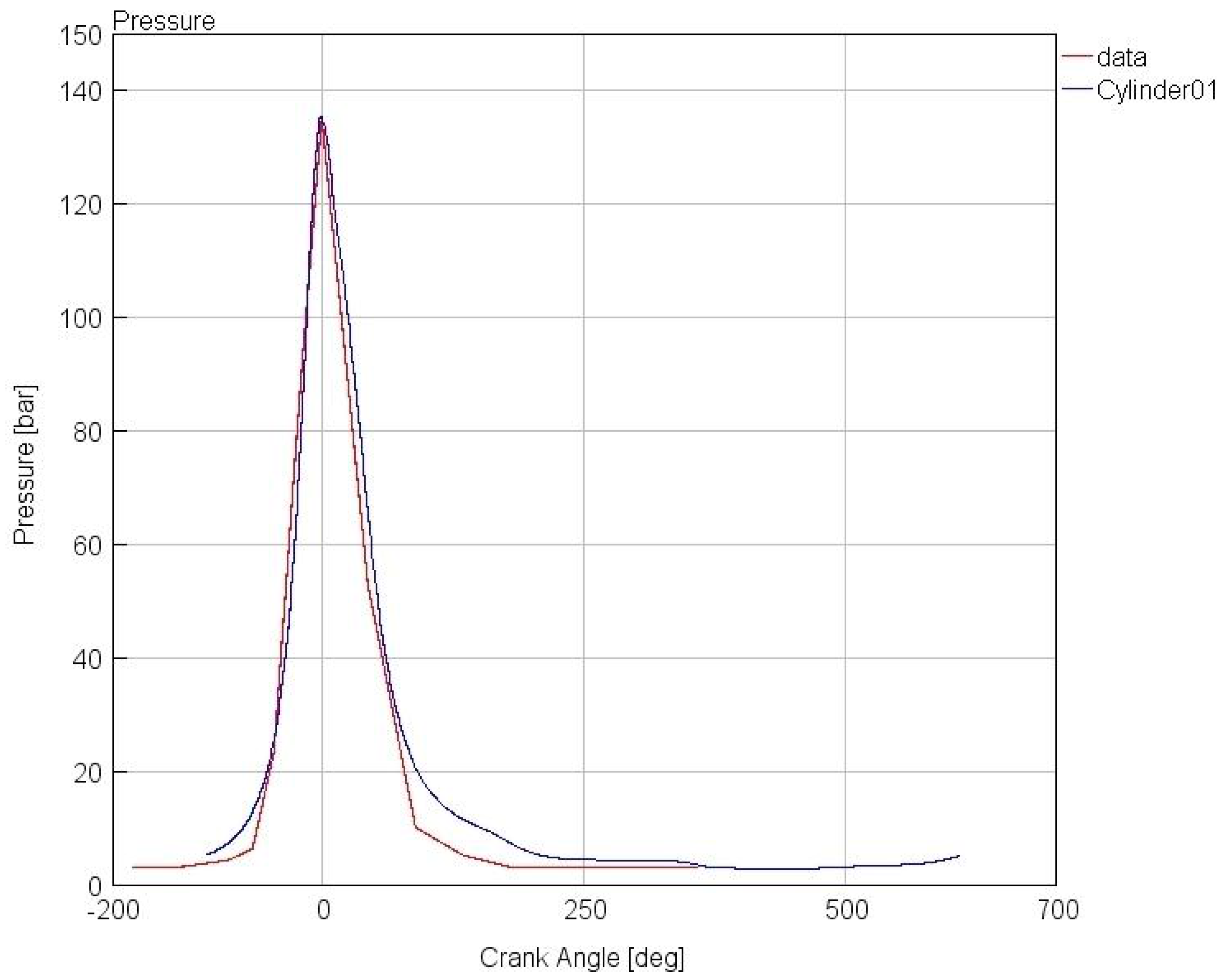
2.1. Engine Modeling

In order to develop the required engine maps and exhaust conditions, the engine model was designed using GT-Power engine simulation software. Engine exhaust conditions will be used as inputs for the ORC simulation. The engine model for this simulation is based on a Boudouin 6-M26-SR P1 Marine diesel engine whose specifications are listed in Table 1:
This engine model was built using GT-Power, as shown in Figure 2. The data input was set at different power targets and RPM ranges to replicate different engine operating conditions.
The model was calibrated at different speed operating points with targeted power output. The engine model calibration is based on experimental in-cylinder pressure and power output data obtained in the literature [28]. The validation results show a good agreement between the selected data and the present simulation, as shown in Table 2 and Figure 3. Table 2 presents the engine simulation values, exhaust gas conditions, and other engine parameters.
The exhaust gas properties have been calculated in the GT-Power model using equations shown in Table 3 (valid for the 400 ≤ T g   200 K), the composition of the exhaust gases was assumed to be 6% CO2, 6% H2O, 11% O2 and 77% N2.
The amount of available heat is calculated based on the following formula when m ˙ g indicates exhaust gas (subscript ‘g’) mass flow rate, T g , in represents exhaust gas temperature before the ORC heat exchanger and T g , out denotes the heat exchanger outlet exhaust gas temperature ≥ 470 K [29].
Q ˙ available   = m ˙ g   c pg ( T g , in T g , out )

2.2. ORC Modeling

The ORC system consists of a dry expansion evaporator, condenser, reservoir, pump, and turbine. First, the pump supplies the working fluid to the evaporator, where the working fluid is heated and vaporized by the exhaust heat. Then, the generated high-pressure vapor is supplied to the turbine to produce power. Lastly, the low-pressure vapor is condensed in the condenser. To complete the closed cycle, the condensed working fluid flows into the reservoir and is pumped back to the evaporator.
This ORC model was designed using GT-Power commercial simulation software, as shown in Figure 4. For the ORC model, the software provided different component templates are used. For different circuit component sizes, system-provided experimental data were used.
The selection of a suitable working fluid is crucial for ORC systems and influences overall system performance. Working fluid properties have significant effects on the turbine performance and size of the whole system. Working fluids are classified based on their saturation vapor diagram as dry, isentropic, and wet fluids, as described earlier. It is important to remark, however, that fluids for ORC applications should not only be favorable from a thermodynamic point of view but also needs to satisfy chemical stability at the operating pressures and temperatures, ensure environmental friendliness, non-toxicity and non-corrosiveness and be compatible with engine materials and possess low flammability and auto-ignition properties.
In lower operating temperature ORCs, the dry and isentropic fluids are very advantageous due to their superheated condition after expansion and eliminate the need for superheating equipment and liquid droplet concerns at the expander. In this study, R245fa was selected as the working fluid due to its suitability for the temperature range of the exhaust gas of marine diesel engines as proposed by [30]. The properties of the selected fluid are given in Table 4:
The thermodynamic properties of the organic fluid under liquid and gaseous conditions and ORC output are also calculated. The model uses standard thermodynamic relations to calculate the fluid conditions at each point of the cycle.
The pump power consumption is calculated as:
W ˙ pump   = m ˙ ref   ( h 7 h 6 ) η p
where h6 and h7 refer to the enthalpy upstream and downstream of the pump, respectively. ηp denotes the pump efficiency. Subscript ‘ref’ for mass flow rate indicates the reference mass flow rate or simply the work fluid average mass flow rate throughout the cycle.
The heat input from the low-grade heat source is calculated by:
Q ˙ in = m ˙ ref   ( h 1 h 7 )
where h1 and h7 refer to the enthalpy downstream and upstream of the evaporator, respectively.
The heat rejected by the condenser is calculated by:
Q ˙ in = m ˙ ref   ( h 5 h 6 )
where h5 and h6 refer to the enthalpy upstream and downstream of the condenser, respectively.
The turbine power output is determined by:
W ˙ turbine   = m ˙ ref   ( h 1 h 5 ) η t
where h1 and h5 refer to the enthalpy downstream of the evaporator (turbine inlet) and downstream of the turbine, respectively. The subscript ‘t’ indicates the ‘turbine’ in the efficiency parameter (η).
The net electric power output from the ORC is denoted by:
W ˙ net   = W ˙ turbine   W ˙ pump  
The thermal efficiency of the ORC cycle is also calculated as the ratio between the net power output and the thermal power input:
η ORC   = W ˙ net   Q ˙ in
For different system components, experimental data were used, and certain variables were set fixed during the simulation based on the fluid specifications and data provided in the software catalog. All other variables were calculated on the bases of components used in the ORC model. This is very important because it allowed us to set some operating parameters for each component, which are fundamental requirements for the subsequent system sensitivity analysis. The simulation objective was to understand the expander input conditions to produce circuit-rated power by varying the mass flow rate. For this, the ‘turbinerefrig’ template was used.
Already set parameters were the exhaust gas mass flow rate, exhaust gas composition, exhaust gas temperature, coolant flow rate (190 L/min), coolant pressure & temperature, pump speed (1750 rpm), turbine speed (40,000 rpm), and the system mass could not exceed 0.8 kg/s due to the system constraint.
Furthermore, for the calculations following assumptions are considered:
  • Each process is considered steady-state;
  • Isentropic pump efficiency η p   65 % ;
  • Turbine isentropic efficiency η t   80 %   ;
  • Evaporating pressure can vary between condensation pressure P cond   , and critical pressure P crit ;
  • Pressure drops and heat losses through the pipelines were neglected.
Based on these factors, expander inlet conditions were evaluated. With the below-described procedure, an in-house turbine design and optimization code is developed to calculate the preliminary turbine design based on assumed expander efficiency and with calculated expander inlet conditions. A brief design code flow chart is shown in Figure 5. With design code, optimization of the expander returns real isentropic efficiency based on different calculated turbine losses.
Finally, an off-design procedure was adopted in this study. The off-design conditions have had an impact on the performance of the total ORC system. For the off-design analysis of the expander, a commercial turbomachinery design and analysis tool, RITAL, was utilized. The expander geometry was imported from the design procedure and was kept constant. Turbine maps were created in RITAL and integrated into the ORC model.
Initially, as stated before, the studied ORC thermodynamic model was used for ORC parameter calculation regarding the organic working fluid mass flow and the pressure ratio by considering previously described parameters. The inlet conditions for the expander were calculated by using the ‘refrig’ template present in the software library. These inputs were used to design the preliminary turbine geometry with an in-house built MATLAB code.
The ORC system design is based on the peak power operating point of the engine (the highest content of exhaust waste heat), which leads to the highest inlet pressure and temperature for the expander and hence higher cycle efficiency. The calculated ORC expander initial conditions are stated in Table 5.
The radial turbine comprises three main components, namely, the volute, nozzle, and rotor. At first, the inlet fluid is accelerated and distributed around the periphery of the turbine via the volute. Then, further acceleration and an increase in the circumferential component of velocity are attained via the nozzle (Before entering the rotor). The empty space between the nozzle and the rotor allows the nozzle outlet wakes to mix out. In radial turbines, the kinetic energy of the fluid is converted into the mechanical energy of the shaft as it expands through the rotor.
A mean-line approach was used to model the radial turbine. The fluid’s properties are assumed to be constant on a plane normal to its direction of motion and vary only in one direction that follows the geometry of blades on the mean streamline. At key stations throughout the stage, the thermodynamic properties, geometry parameters and flow features are determined. The Euler turbo-machinery equation and fluid dynamics principles such as conservation of mass, momentum and energy are the basic equations used in the model. Flow losses and blockage are included in the model. Inputs to the mean-line model consist of the turbine inlet total temperature and pressure, rotational speed, geometry ratios, and non-dimensional parameters, as listed in Table 6.
The model determines the rotor’s fundamental geometry, flow characteristics, and thermodynamic properties at the rotor inlet and exit using the estimated turbine total-to-static efficiency and the input variables given in Table 6. The general features of the remaining turbine components are established based on the results.
The model defines an accurate estimation of the turbine efficiency by using these results and taking into account the loss correlations. This value is then used as the initial guess for the turbine efficiency, and the process is iterated until convergence is achieved.
For the assessment of the ORC-equipped power train, the impact on BSFC was calculated as follows. Brake-specific fuel consumption (BSFC) is a measure of the fuel efficiency of any prime mover that burns fuel and produces rotational or shaft power.
B S F C   combined   = m ˙ fuel   W ˙   engine + W ˙   net ,   ORC
BSFC   improvement   ( % ) = BSFC engine   BSFC combined   BSFC engine   × 100
W ˙   combined = W ˙   engine + W ˙   net ,   ORC
Powertrain   power   improvement   ( % ) = W ˙   combined W ˙   engine W ˙   engine × 100
where, W ˙   combined is the combined power generated by the engine and ORC, W ˙   engine is the power of the engine, W ˙   net ,   ORC is the net power output generated by the ORC system itself.
After the design-point analysis that is presented, an off-design method was utilized to explore the performance characteristics of the expander and the ORC system at different engine operating conditions. The expander geometry was imported from the design procedure. Turbine maps for different speed and pressure ratios were created by using RITAL results integrated into the ORC system turbo-expander template, and ORC performance was calculated using the earlier stated equations.
Figure 6 and Figure 7 illustrate the off-design analysis of expander efficiency and power output. These maps were created in RITAL with different speed and pressure ratios. It can be seen that turbine efficiency and power output are highly related to the rotational speed and (U/C) ratio.
Slight changes in inlet conditions can result in significant differences in expander performance. It can also be seen that when maintaining turbine design speed, the change in efficiency is lower compared to changes in power output which occur at a higher rate.
It is clear from Table 7 that expander efficiency doesn’t change considerably. However, power output changes significantly at different engine operating points. The main reason for this seems to be related to the available extracted heat from the evaporator. The available heat is lower, and therefore, the useful shaft power output is also lower. Figure 8 illustrates the ORC efficiency at different engine speeds.

3. Results and Discussion

The result of the ORC sensitivity analysis and the influence of coolant flow rate is discussed in this section. Improved fuel efficiency and powertrain power improvement were studied to highlight the benefits of WHR integration in the engine.

3.1. Sensitivity Analysis

For the design point analysis, certain parameters were considered constant, i.e., coolant flow rate (at 190 L/min, for example), etc. In the sensitivity analysis, the effect of these parameters on the ORC performance can be seen in Figure 9. It can be seen that cycle efficiency increases (from 17.4% to 19.4%) with the increase of coolant flow rate (from 150 to 230 L/min) when keeping all other parameters constant. Meanwhile, turbine output enthalpy is a function of condenser pressure. Condenser pressure is affected by the cooling water temperature and mass flow rate. By increasing the coolant flow rate (as discussed above) with a given inlet temperature, condensing pressure decreases, due to which the turbine pressure ratio increases, which results in a high-power output (for the same coolant increase span the net power output increases by 12.8%, from 12.1 kW to 13.65 kW). With the increase in output, cycle efficiency also increases, as discussed previously in this paragraph.
There are some cautions to be observed in increasing the coolant flow rate, however. Going too far may result in the aeration and foaming of the coolant due to excessive pressure drop. In addition, there are certain limitations in the reduction of condenser pressure. The turbine outlet loss increases when reducing condenser pressure. In fact, the reduction of condenser pressure decreases the exiting charge quality or increases the chances of droplet formation at the turbine outlet, which could lead to erosion of the turbine blades. Net power output and refrigerant mass flow rate relations are shown in Figure 10.

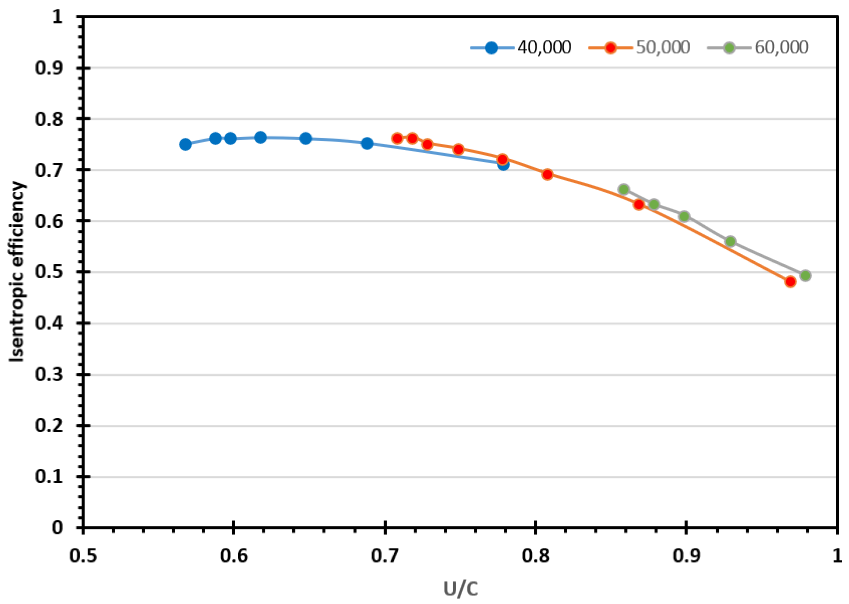
3.2. ORC Equipped Powertrain

One of the challenges facing engine manufacturers is meeting exhaust emissions regulations. At the same time, the ORC system can also improve fuel consumption and increase powertrain power. In this study, the gains of the ORC system on the performance and fuel consumption of the engine are studied as listed in Table 8.
Brake-specific fuel consumption (BSFC), as a measure of the fuel efficiency for any prime mover that burns fuel and produces shaft work, is introduced. From Figure 11, it can be seen that the WHR system can improve engine brake-specific fuel consumption by a maximum of 5.14% and by a minimum of 2.9%. This engine BSFC improvement due to the ORC is the improvement on the original engine-only BSFC data presented in Table 2. The potential benefit of the ORC system on fuel consumption is highest when the engine is operating at full load conditions.
The effect of the ORC system on the integrated powertrain power is also studied. It can be seen in Figure 12 that the trends for improvement depend on the engine’s operating point. This engine power improvement due to the ORC is the improvement on the original engine-only power data presented in Table 2. At the lowest engine speed operating point, the powertrain power output is increased by 3.05%, but at the engine’s highest power point (1800 rpm), the maximum power of the integrated unit increased by 5.42%.

4. Conclusions

In this study, a WHR ORC system is modeled for a marine diesel engine. A MATLAB-based expander design code developed by the research team is utilized in calculating different expander geometrical characteristics. In addition, an off-design study is carried out for different engine operating conditions. For this analysis, an in-house design and optimization code and commercial turbo-machinery analysis software RITAL were combined to collectively analyze on- and off-design cases.
It is shown that the cycle thermal efficiency is highly influenced by the engine operating conditions. At high engine speeds, the cycle shows improved performance due to the higher energy contents available and hence the higher quantity of the fluid being evaporated. The developed WHR also affects the overall engine performance and also helps to reduce overall fuel consumption by producing power from exhaust gases. It can be seen that this WHR can affect engine BSFC in the range of 2.9–5.1%, depending on engine operating conditions. It can also increase overall engine power by up to 3.05–5.42% depending on engine operating conditions in case there an appropriate mechanical connection is made between the expander shaft and the engine shaft. ORC performance is sensitive to various circuit parameters, i.e., coolant mass flow rate, refrigerant mass flow rate, available heat, heat exchanger efficiency etc. It shows an increasing trend in net power output with the increase of system refrigerant mass flow rate. ORC efficiency also increases with the increase of coolant flow rate due to the reduction of condensation pressure. There are certain restrictions in changing the circuit parameters, which must be taken into account to design an optimum performance cycle.
The present study was limited by the 1D nature of the simulation, and considering the sensitivity of ORC systems to expander performance and coupled model with advanced CFD methods (found in literature) would further improve model fidelity.
The results provide encouragement for strengthening and tightening marine emissions regulations on the part of policymakers while also providing an economic incentive for large fleet owners and operators. The present study and efficiency enhancements in these sectors are absolutely essential, and further improvements in the architecture and component design of such WHR systems are required in order to help decarbonize a field that cannot simply benefit from large-scale battery technology and electrical energy storage alternatives and their implementation.

Author Contributions

Conceptualization, Data curation, Investigation, A.P.; Data curation, Investigation, Writing—original draft, M.S.A.; Writing—original draft, Data curation, Illustrations, S.M.; Supervision, Methodology, Validation, Writing—review & editing, A.M.A.; Supervision, Methodology, Writing-review & editing, A.G.; Super-vision, Resources, Writing—review & editing, T.M. All authors have read and agreed to the published version of the manuscript.

Funding

This research received no external funding.

Data Availability Statement

Data available on request due to privacy.

Conflicts of Interest

The authors declare no conflict of interest.

References

  1. International Energy Agency. World Energy Outlook 2008 and World Energy Outlook 2022; International Energy Agency: Paris, France, 2022. [Google Scholar]
  2. Mehranfar, S.; Gharehghani, A.; Azizi, A.; Andwari, A.M.; Pesyridis, A.; Jouhara, H. Comparative assessment of innovative methods to improve solar chimney power plant efficiency. Sustain. Energy Technol. Assess. 2022, 49, 101807. [Google Scholar] [CrossRef]
  3. Corbett, J.J.; Koehler, H.W. Updated emissions from ocean shipping. J. Geophys. Res. Atmos. 2003, 108, 4650. [Google Scholar] [CrossRef]
  4. Moradi, J.; Gharehghani, A.; Mirsalim, M. Numerical investigation on the effect of oxygen in combustion characteristics and to extend low load operating range of a natural-gas HCCI engine. Appl. Energy 2020, 276, 115516. [Google Scholar] [CrossRef]
  5. Moradi, J.; Gharehghani, A.; Mirsalim, M. Numerical comparison of combustion characteristics and cost between hydrogen, oxygen and their combinations addition on natural gas fueled HCCI engine. Energy Convers. Manag. 2020, 222, 113254. [Google Scholar] [CrossRef]
  6. Gharehghani, A.; Mirsalim, S.M.; Jazayeri, S.A. Numerical and Experimental Investigation of Combustion and Knock in a Dual Fuel Gas/Diesel Compression Ignition Engine. J. Combust. 2012, 2012, 504590. [Google Scholar] [CrossRef]
  7. Gharehghani, A.; Kakoee, A.; Andwari, A.M.; Megaritis, T.; Pesyridis, A. Numerical Investigation of an RCCI Engine Fueled with Natural Gas/Dimethyl-Ether in Various Injection Strategies. Energies 2021, 14, 1638. [Google Scholar] [CrossRef]
  8. Yang, N.; Deng, X.; Liu, B.; Li, L.; Li, Y.; Li, P.; Tang, M.; Wu, L. Combustion Performance and Emission Characteristics of Marine Engine Burning with Different Biodiesel. Energies 2022, 15, 5177. [Google Scholar] [CrossRef]
  9. Andwari, A.M.; Pesyridis, A.; Esfahanian, V.; Said, M. Combustion and Emission Enhancement of a Spark Ignition Two-Stroke Cycle Engine Utilizing Internal and External Exhaust Gas Recirculation Approach at Low-Load Operation. Energies 2019, 12, 609. [Google Scholar] [CrossRef]
  10. Andwari, A.M.; Said, M.F.M.; Aziz, A.A.; Esfahanian, V.; Zadeh, A.S.; Idris, M.A.; Perang, M.R.M.; Jamil, H.M. Design, modeling and simulation of a high-pressure gasoline direct injection (GDI) pump for small engine applications. J. Mech. Eng. 2018, 1, 107–120. [Google Scholar]
  11. Hountalas, T.D.; Founti, M.; Zannis, T.C. Experimental Investigation to Assess the Performance Characteristics of a Marine Two-Stroke Dual Fuel Engine under Diesel and Natural Gas Mode. Energies 2023, 16, 3551. [Google Scholar] [CrossRef]
  12. Theotokatos; Livanos, G. Techno-economical analysis of single pressure exhaust gas waste heat recovery systems in marine propulsion plants. Proc. Inst. Mech. Eng. Part M J. Eng. Marit. Environ. 2012, 227, 83–97. [Google Scholar] [CrossRef]
  13. Di Battista, D.; Cipollone, R. Waste Energy Recovery and Valorization in Internal Combustion Engines for Transportation. Energies 2023, 16, 3503. [Google Scholar] [CrossRef]
  14. Mariani, A.; Morrone, B.; Laiso, D.; Prati, M.V.; Unich, A. Waste Heat Recovery in a Compression Ignition Engine for Marine Application Using a Rankine Cycle Operating with an Innovative Organic Working Fluid. Energies 2022, 15, 7912. [Google Scholar] [CrossRef]
  15. Sun, Y.; Sun, P.; Zhang, Z.; Zhang, S.; Zhao, J.; Mei, N. Performance Prediction for a Marine Diesel Engine Waste Heat Absorption Refrigeration System. Energies 2022, 15, 7070. [Google Scholar] [CrossRef]
  16. Sadeghi, S.; Mehranfar, S.; Ghandehariun, S. Analysis and optimization of a hybrid solar-ocean powered trigeneration system for Kish Island. In Proceedings of the 28th Annual International Conference of the Iranian Association of Mechanical Engineers, Tehran, Iran, 27 May 2020; Volume 27. [Google Scholar]
  17. Shu, G.; Liang, Y.; Wei, H.; Tian, H.; Zhao, J.; Liu, L. A review of waste heat recovery on two-stroke IC engine aboard ships. Renew. Sustain. Energy Rev. 2013, 19, 385–401. [Google Scholar] [CrossRef]
  18. Andwari, A.M.; Pesiridis, A.; Karvountzis-Kontakiotis, A.; Esfahanian, V. Hybrid Electric Vehicle Performance with Organic Rankine Cycle Waste Heat Recovery System. Appl. Sci. 2017, 7, 437. [Google Scholar] [CrossRef]
  19. Varshil, P.; Deshmukh, D. A comprehensive review of waste heat recovery from a diesel engine using organic rankine cycle. Energy Rep. 2021, 7, 3951–3970. [Google Scholar] [CrossRef]
  20. Song, J.; Song, Y.; Gu, C.W. Thermodynamic analysis and performance optimization of an Organic Rankine Cycle (ORC) waste heat recovery system for marine diesel engines. Energy 2015, 82, 976–985. [Google Scholar] [CrossRef]
  21. Reini, M.; Pinamonti, P. Different Options for ORC’s as Bottom for an Internal Combustion Engine for Ship propulsion. Energies 2015, 8, 4273–4299. [Google Scholar]
  22. Andwari, A.M.; Pesiridis, A.; Esfahanian, V.; Salavati-Zadeh, A.; Karvountzis-Kontakiotis, A.; Muralidharan, V. A Comparative Study of the Effect of Turbocompounding and ORC Waste Heat Recovery Systems on the Performance of a Turbocharged Heavy-Duty Diesel Engine. Energies 2017, 10, 1087. [Google Scholar] [CrossRef]
  23. Andwari, A.M.; Pesyridis, A.; Esfahanian, V.; Salavati-Zadeh, A.; Hajialimohammadi, A. Modelling and Evaluation of Waste Heat Recovery Systems in the Case of a Heavy-Duty Diesel Engine. Energies 2019, 12, 1397. [Google Scholar] [CrossRef]
  24. Yun, E.; Park, H.; Yoon, S.Y.; Kim, K.C. Dual parallel organic Rankine cycle (ORC) system for high efficiency waste heat recovery in marine application. J. Mech. Sci. Technol. 2015, 29, 2509–2515. [Google Scholar] [CrossRef]
  25. Opcon. Commissioning and testing of first reference installation of Opcon technology for ships. Erişim Tar. 2012, 15, 15. [Google Scholar]
  26. Bellolio, S.; Lemort, V.; Rigo, P.; Organic Rankine Cycles Systems for Waste Heat Recovery in Marine Applications. SCC 2015, International Conference on Shipping in Changing Climates, Nov. 2015. Available online: https://orbi.uliege.be/handle/2268/189044 (accessed on 29 November 2022).
  27. De La Fuente, S.S. Making shipping greener: ORC modelling under realistic operative conditions. In Proceedings of the Low Carbon Shipping Conference 2013; Smith, T., Ed.; Low Carbon Shipping & Shipping in Changing Climates: London, UK, 2013; Available online: http://www.lowcarbonshipping.co.uk/index.php?option=com_content&view=article&id=29&Itemid=164 (accessed on 29 November 2022).
  28. Nahim, H.M.; Younes, R.; Nohra, C.; Ouladsine, M. Complete modeling for systems of a marine diesel engine. J. Mar. Sci. Appl. 2015, 14, 93–104. [Google Scholar] [CrossRef]
  29. Alshammari, F.; Karvountzis-Kontakiotis, A.; Pesiridis, A. Radial Turbine Expander Design for Organic Rankine Cycle, Waste Heat Recovery in High Efficiency, Off-Highway Vehicles. In Proceedings of the 3rd Biennial International Conference on Powertrain Modelling and Control; 2016. Available online: http://bura.brunel.ac.uk/handle/2438/13953 (accessed on 29 November 2022).
  30. Wang, E.H.; Zhang, H.G.; Fan, B.Y.; Ouyang, M.G.; Zhao, Y.; Mu, Q.H. Study of working fluid selection of organic Rankine cycle (ORC) for engine waste heat recovery. Energy 2011, 36, 3406–3418. [Google Scholar] [CrossRef]
  31. Fiaschi, D.; Manfrida, G.; Maraschiello, F. Thermo-fluid dynamics preliminary design of turbo-expanders for ORC cycles. Appl. Energy 2012, 97, 601–608. [Google Scholar] [CrossRef]
  32. Rahbar, K.; Mahmoud, S.; Al-Dadah, R.K.; Moazami, N. Modelling and optimization of organic Rankine cycle based on a small-scale radial inflow turbine. Energy Convers. Manag. 2015, 91, 186–198. [Google Scholar] [CrossRef]
Figure 1. World consumption in a million tonnes of oil equivalent.
Energies 16 04374 g001
Figure 2. GT-Power engine model.
Energies 16 04374 g002
Figure 3. Engine cylinder pressure at 1440 rpm.
Energies 16 04374 g003
Figure 4. GT-Power builds the ORC model.
Energies 16 04374 g004
Figure 5. Flowchart of the turbine design procedure.
Energies 16 04374 g005
Figure 6. Expander off-design analysis and Isentropic efficiency.
Energies 16 04374 g006
Figure 7. Expander off-design analysis and power output.
Energies 16 04374 g007
Figure 8. ORC efficiency at different engine speeds.
Energies 16 04374 g008
Figure 9. Effect of Coolant VFR on ORC performance.
Energies 16 04374 g009
Figure 10. Net power output and refrigerant mass flow rate.
Energies 16 04374 g010
Figure 11. BSFC improvement in different engine speeds.
Energies 16 04374 g011
Figure 12. Powertrain power improvement in different engine speeds.
Energies 16 04374 g012
Table 1. Engine main specification.
ParameterRange
No. of Cylinders6
Bore150 mm
Stroke150 mm
Displacement15.9 dm3
Compression ratio14
Max Speed1800 RPM
Weight1870 kg
Annual working time5000 h
Table 2. Engine simulation results.
Parameter Engine Simulation
Speed (RPM) 1000130014401800
Power (kW) 200.07275.14297.0335
Exhaust MFR (kg/s) 0.3690.5790.6270.649
Exhaust Temp (K) 674.83627.56641.17711.93
BSFC (g/kWh) 219.96228.38237.5264.2
Torque (Nm) 1910.602021.981969.541777.23
Table 3. Equation for exhaust gas properties calculations.
ParameterFormula
Specific heat capacity [J/kg-K] c p = 956 + 0.3386 T g 2.476 * 10 5 T g 2
Dynamic Viscosity [Nsm−2] μ g = 10 6 * ( 3.807 + 4.731 * 10 2 T g 9.945 * 10 6 T g 2 )
Thermal conductivity [Wm−1K−1] k g = 10 3 * ( 4.643 + 6.493 * 10 2 T g )
Density [kg m−3] ρ g = 1.665 2.404 * 10 3 T g + 1.121 * 10 6 T g 2
Table 4. ORC working fluid properties.
ParameterCategoryMolecular Weight (g/mol)Pcr [Mpa]Boiling Temp. [°C]ODPAtm. Life
Time (yr)
R245faHFC (dry)134.053.6414.807.2
Table 5. ORC (simulated) values at the maximum engine power point.
ParameterUnitValues
Mass flow rate of exhaust gas kg/s0.649
Temperature of exhaust gas K711.93
Mass flow rate kg/s0.73
Expander inlet pressure Bar22.015
Expander inlet temperature K457.13
Pressure ratio -5.01
Power output kW20.194
Pump absorbed power kW2.017
ORC net power output kW18.177
Table 6. Input parameters of the turbine model [31,32].
ParameterValues/Range
Loading coefficient ( ψ ) 0.8–1.5
Flow coefficient ( φ ) 0.2–0.5
Rotors exit hub to inlet radii ratio ( r 5 h u b / r 4 ) 0.2–0.3
Nozzle inlet to exit radii ratio ( r 2 / r 3 ) 1.2–1.3
Volute swirl coefficient ( S C ) 0.95
Volute pressure loss coefficient ( k v o l u t e ) 0.1
Flow blockage factor ( B K ) 0.1
Table 7. Cycle parameters for different engine speeds.
Parameter Off-Design Points Design Point
Engine speed (RPM)1000130014401800
P (bar)15.8417.7219.5622.01
T (K)383.58388.99408.66457.13
Speed (RPM)40,00040,00040,00040,000
Qin (kW)84.8197.39114.28142.09
W net   (kW)6.128.8112.4018.17
η ORC   (%)7.219.0510.812.7
η t   (%)75.0275.9274.0074.44
η p   (%)65656565
Table 8. Impact on engine performance.
Engine Power (kW)BSFC of Engine
(kg/kWh)
Fuel Flow Rate
(kg/h)
Combined Power
(kW)
BSFC
Combined (kg/kWh)
BSFC
Improvement (%)
Power Increase (%)
2000.2199093144.02206.260.2134152.9531953.05
2750.2283833262.86284.070.2213133.0956383.20
3050.2418781573.81317.590.2324053.9163864.07
3350.2642762488.62353.510.2506875.1420835.42
Disclaimer/Publisher’s Note: The statements, opinions and data contained in all publications are solely those of the individual author(s) and contributor(s) and not of MDPI and/or the editor(s). MDPI and/or the editor(s) disclaim responsibility for any injury to people or property resulting from any ideas, methods, instructions or products referred to in the content.

