Review

A Review of Bionic Structures in Control of Aerodynamic Noise of Centrifugal Fans

1
College of Metrology & Measurement Engineering, China Jiliang University, Hangzhou 310018, China
2
School of Mechanical and Automotive Engineering, Zhejiang University of Water Resources and Electric Power, Hangzhou 310018, China
*
Authors to whom correspondence should be addressed.
Energies 2023, 16(11), 4331; https://doi.org/10.3390/en16114331
Submission received: 19 April 2023 / Revised: 12 May 2023 / Accepted: 20 May 2023 / Published: 25 May 2023
(This article belongs to the Section A3: Wind, Wave and Tidal Energy)

Abstract

:
Due to the complexity of the working conditions and the diversity of application scenarios, the normal operation of a fan, whether volute tongue, volute shell surface, or blade, often encounters some unavoidable problems, such as flow separation, wear, vibration, etc.; the aerodynamic noise caused by these problems has a significant impact on the normal operation of the fan. However, despite the use of aerodynamic acoustics to design low-noise fans or the use of sound absorption, sound insulation, and sound dissipation as the main traditional noise control techniques, they are in a state of technical bottleneck. Thus, the search for more efficient methods of noise reduction is looking toward the field of bionics. For this purpose, this paper first analyzes the mechanism of fan noise in the volute tongue and blades, and then, this paper reviews the noise control mechanism and improvement research using the bionic structures in the volute tongue structure, the contact surface of the volute shell, and the leading and trailing edges of the blade in the centrifugal fan. Finally, the current challenges and prospects of bionic structures for aerodynamic noise control of centrifugal fans are discussed.

1. Introduction

Bionics is a comprehensive interdisciplinary science that applies the mechanisms and rules found in the biological world to address human needs and uses the principles of the structure and function of natural biological systems to make conscious imitations and replications. Since its first introduction by Steele in 1960, bionics has been on a “highway” of rapid development, with great achievements in a wide range of technical engineering projects and scientific research and cross-cutting areas [1,2,3,4,5].
With the development of modern science and technology and the practical needs of engineering, numerous counterparts of bionic technology research and cutting-edge technology exploration are responding in their engineering and technology fields. Recently, bionics has been evolving from unitary bionics where one aspect or factor of biology is learned to couple bionics where simultaneous, multi-factor learning takes place, and the scale of bionics is not only moving from macroscopic to microscopic but also starting to move to the finer scale of the nanoscale. Bionic technology, with emerging examples of applied research in engineering resistance reduction, efficiency, and noise reduction, has achieved remarkable results in efficiently and accurately suppressing noise generation [6,7,8,9].
The fan is the short name for machinery used for the compression of gases and their transport. With the development of society and people’s awareness of environmental protection, the requirements for fans are becoming increasingly high, and noise problems have become the focus of research in recent years. Whether the noise of a car’s engine, a power plant’s wind turbine, a construction site’s blower, or a home’s exhaust fan, there is no doubt that fan noise has a major impact [10]. The negative effects of aerodynamic noise have become increasingly evident as the speed of working parts increases. In many cases, the impact of aerodynamic noise has far exceeded that of mechanical noise and then dominates the total noise. Noise specifications have become one of the most important design criteria in large vehicles and impeller types of machinery such as gas turbines, fans, and wind turbines [11]. However, the design of low-noise fans using the principles of aerodynamic acoustics and the use of sound absorption, sound insulation, sound dissipation, damping, and vibration damping as the main traditional noise control technologies are in a state of a technical bottleneck. The choice to find more efficient noise reduction methods is thus placed in the field of bionics [12].
This paper focuses on centrifugal fan noise as the main object of study, taking into account recent successful applications of bionics for noise reduction in several engineering fields, as well as several successful cases of improvement and design using bionics in key components. A systematic review of bionics work in the field of centrifugal fans noise reduction is given, the history of bionics research in aerodynamic noise control technology is recapitulated, and a summary of existing results and real-time developments in bionics noise reduction research on the leading and trailing edges of blades are emphasized, thus offering some guidance in the search for more effective wind turbine noise reduction methods.

2. Noise Generation Mechanism of Centrifugal Fans

Aerodynamic noise is the main source of fan noise, and the main reason for aerodynamic noise is the fluid in the flow with the surrounding object’s impact and friction caused by the process. Aerodynamic noise generally does not have prominent peaks in the spectral analysis and exhibits broadband characteristics [13,14]. During the operation of the fan, the rotation of the impeller leads to a reduction in the pressure stability of the flow field inside the fan, and this type of noise, which also includes harmonics of various orders and has discrete characteristics, is called rotational noise. In addition, due to the impeller surface fluid pressure changes, speed fluctuations, as well as the surface of the vortex broken, shedding, etc. caused by the main distribution in a certain range of the spectrum, with broad frequency characteristics of the noise, is called turbulence noise [15,16].

2.1. The Generation Mechanism of Volute Tongue Noise

The main source of aerodynamic noise of centrifugal fans is the impeller blades and volute tongue, and the rotating noise accounts for the main part of the volute tongue noise [17]. The main function of the volute tongue is to reduce the circular flow of some of the gas that returns to the volute housing when the fan is in operation, preventing losses in efficiency and power consumption of the fan. The volute tongue area is generally accompanied by a vortex structure of some intensity, especially when it deviates from the rated operating point, and the area between the impeller and the worm tongue generates complex turbulence, which is an inevitable cause of worm tongue noise [18,19].

2.2. The Generation Mechanism of Blade Noise

The aerodynamic noise of the blade is mainly composed of turbulent boundary layer trailing-edge noise, the vortex shedding noise of the boundary layer of laminar flow, boundary layer separation noise, the noise generated by stall speed, the noise generated by trailing-edge passivization, and wing tip noise [20], whose generation mechanism is shown in Figure 1.
Figure 1a. The turbulent boundary layer trailing-edge noise is mainly composed of monopole noise and dipole noise distributed on the blade surface, as well as volume-distributed dipole noise and quadrupole noise. Under high Reynolds number conditions, as the turbulent boundary layer flows over the trailing edge of the blade, it gradually separates or clings to the trailing edge and the monopoles gradually disappear, which leaves volume-distributed dipoles and surface-distributed dipoles to generate broadband noise [21].
Figure 1b. Laminar boundary layer vortex shedding noise is mainly at low Reynolds numbers. As the airflow through the blade passes through the unstable laminar boundary layer, the T-S wave that forms on the surface on the other side of the blade intensifies between the leading and trailing edges, generating transverse vibrations at the trailing edge and, consequently, vortex-shedding noise [22].
The noise generated by trailing-edge passivization depends primarily on the size and thickness of the trailing edge of the blade. Generally, the noise generated by trailing-edge passivization is positively correlated with the speed, and as the speed of rotation increases, the dominant frequency of the noise generated by trailing-edge passivization decreases from high to low frequencies [23].
Figure 1c,d. The boundary layer separation noise and large-scale separation noise are mainly due to the non-zero angle of attack conditions; the boundary layer will gradually separate near the trailing edge, and the blade suction surface will increase because of the turbulent vortex off the trailing-edge noise. Under different conditions of the angle of attack, the noise at the stall point or the trailing edge noise in the turbulent boundary layer will increase to different degrees [24].
Figure 1e,f. Wing tip noise is usually due to the high-frequency noise generated by the interaction between the blade tip vortex and the separated flow at the head of the blade, and the wing tip noise prominently exhibits quadrupole characteristics. Reducing the wing tip noise needs to be specific to the object of study, as well as the operating conditions. Blade tip noise is usually an important noise design index that cannot be ignored when designing blades for wings and rotating machinery [25].

3. Research and Development of Bionic Structures for Noise-Reduction Control in Centrifugal Fans

3.1. Research on Noise Reduction of the Volute Tongue

The aerodynamic noise has an important influence on the working stability and performance of large centrifugal fans, and the volute tongue noise accounts for the majority of the aerodynamic noise of large centrifugal fans. The main cause of the noise of the volute tongue of the centrifugal fan is the collision and shock between the exhaust flow of the centrifugal impeller and the volute tongue. Therefore, by changing the parameters of the volute tongue flow boundary layer, the boundary layer separation is delayed, and the vortex shedding of the airflow at the trailing edge of the volute tongue is prevented, which can effectively control the airflow noise of the centrifugal fan [26].
According to the observation and research on the surface noise reduction characteristics of long-eared owls, scholars found that the wing feathers of the long-eared owl were soft and loose, and this feature was applied to the noise reduction in snail tongue [27].
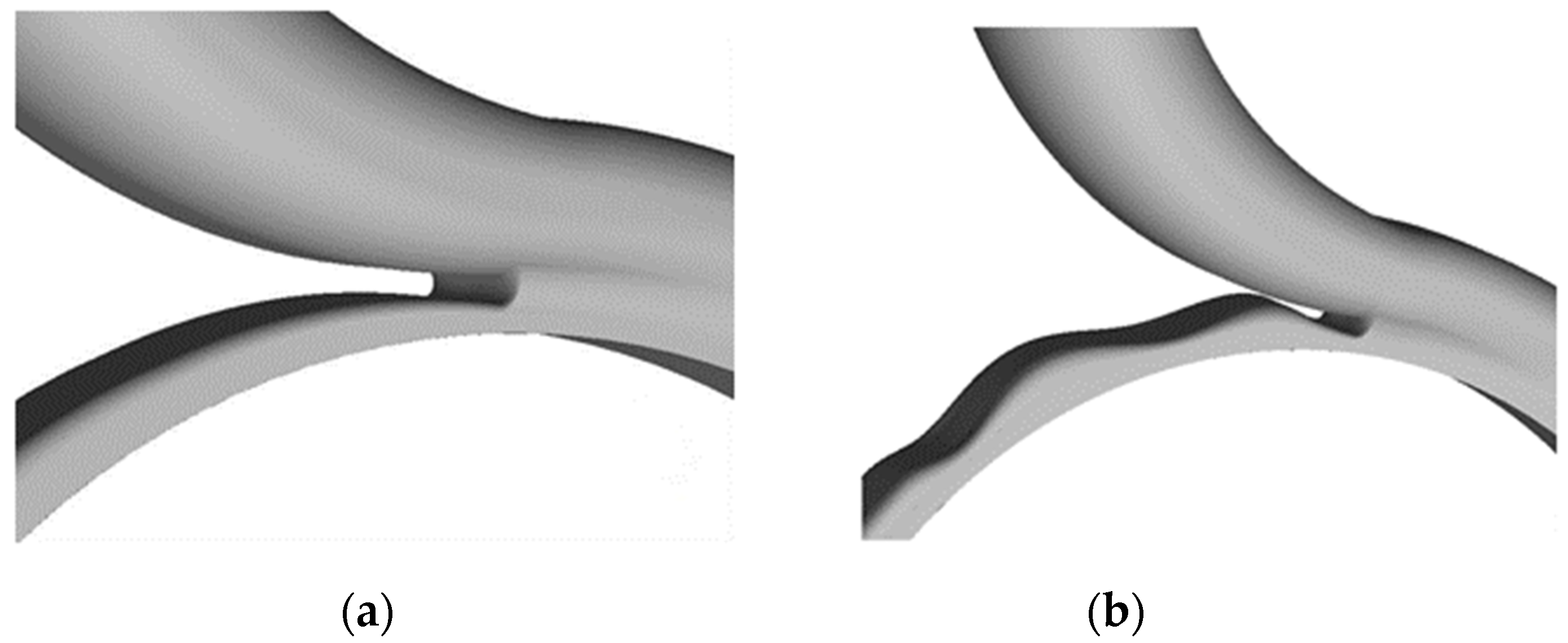
The long-eared owl’s body surface noise-reduction characteristics were first applied to a centrifugal fan in which the existence of noise and vibration control was a problem [28]. The bionic volute structure size and positioning integrated the bionic noise-reduction technology of the centrifugal fan, as shown in Figure 2. Among them, the bionic non-smooth surface referred to the linear sinusoidal surface structure with a circular arc tooth structure [29].
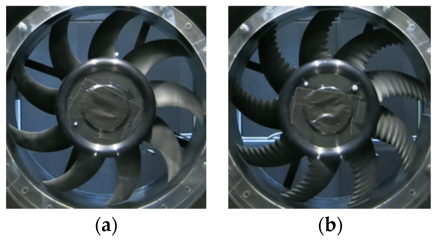
Early bionic non-smooth surfaces were often characterized by a sine function. To further reduce overall noise, the design of the bionic volute tongue takes into account both the surface morphology of the long-eared owl’s wings and the configuration of the noise-reduction features [30]. The bionic volute tongue is applied to the centrifugal fan noise control.
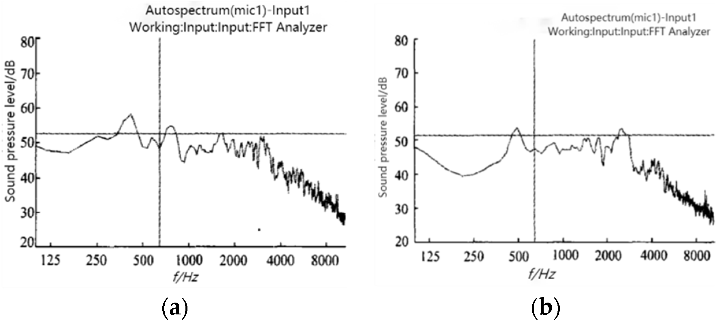
Through experiments and simulations, combined with the classical FW-H equation, it was concluded that the total sound pressure level of the bionic fan in the whole frequency band was lower than that of the prototype fan, and the average sound pressure level was reduced by 2.3 dB. The velocity distribution on the bionic tongue surface was relatively uniform, and the velocity change was relatively flat; it can effectively suppress the turbulence intensity in the flow field on the tongue surface, which can reduce the impact of airflow on the tongue to a large extent, causing the shedding vortex to be delayed or reduced, thereby decreasing the sound energy and reducing the noise [31].
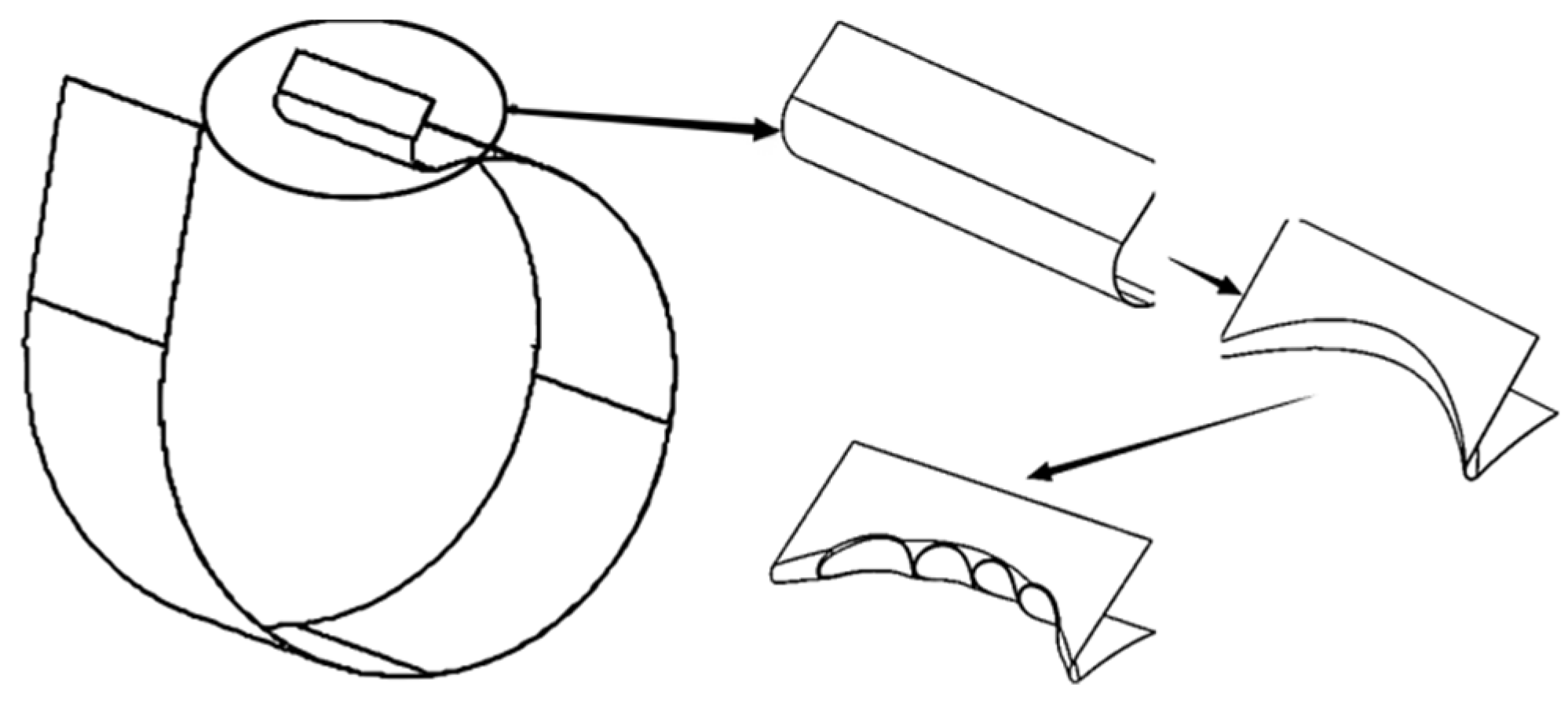
Inspired by the non-smooth leading edge of long-eared owl wings, the bionic tongue structure was applied to reduce the aerodynamic noise of the centrifugal fan [32]. The geometry of the bionic volute tongue is shown in Figure 3.
The results show that compared with the original fan, the impact strength of the impeller outlet airflow on the volute tongue was reduced, and the reverse pressure gradient of the flow field at the volute tongue was reduced, which made the aerodynamic noise of the fan decrease.
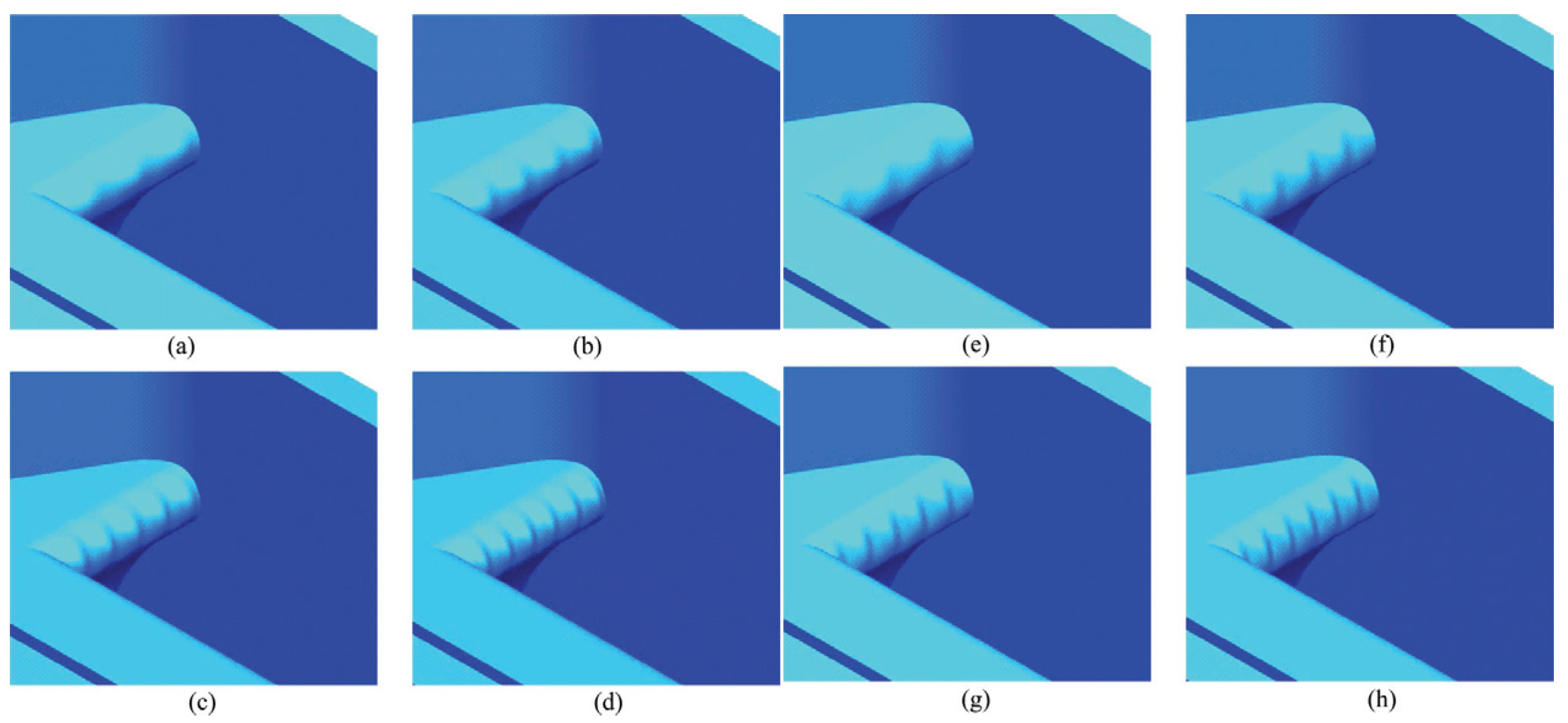
As the non-smooth leading edge of the long-eared owl has received more attention, eight volute shells incorporating bionic structures have been used for noise control in centrifugal fans [33,34]. The geometry of the established bionic volute tongue is shown in Figure 4.
A non-smooth worm tongue is formed using different groups and depths of groove bionic structures as shown in the diagram above, ane the results show that the surface of the volute shell of the centrifugal fan reduces the intensity of the vortex upstream and downstream of the volute tongue under the working conditions of the blade passing frequency and significantly improves the pressure pulsation on the surface of the worm shell, which reduces the noise of the blade passing frequency and the odd harmonic frequency noise, which in turn reduces the total sound pressure level by up to 1.5 dB.
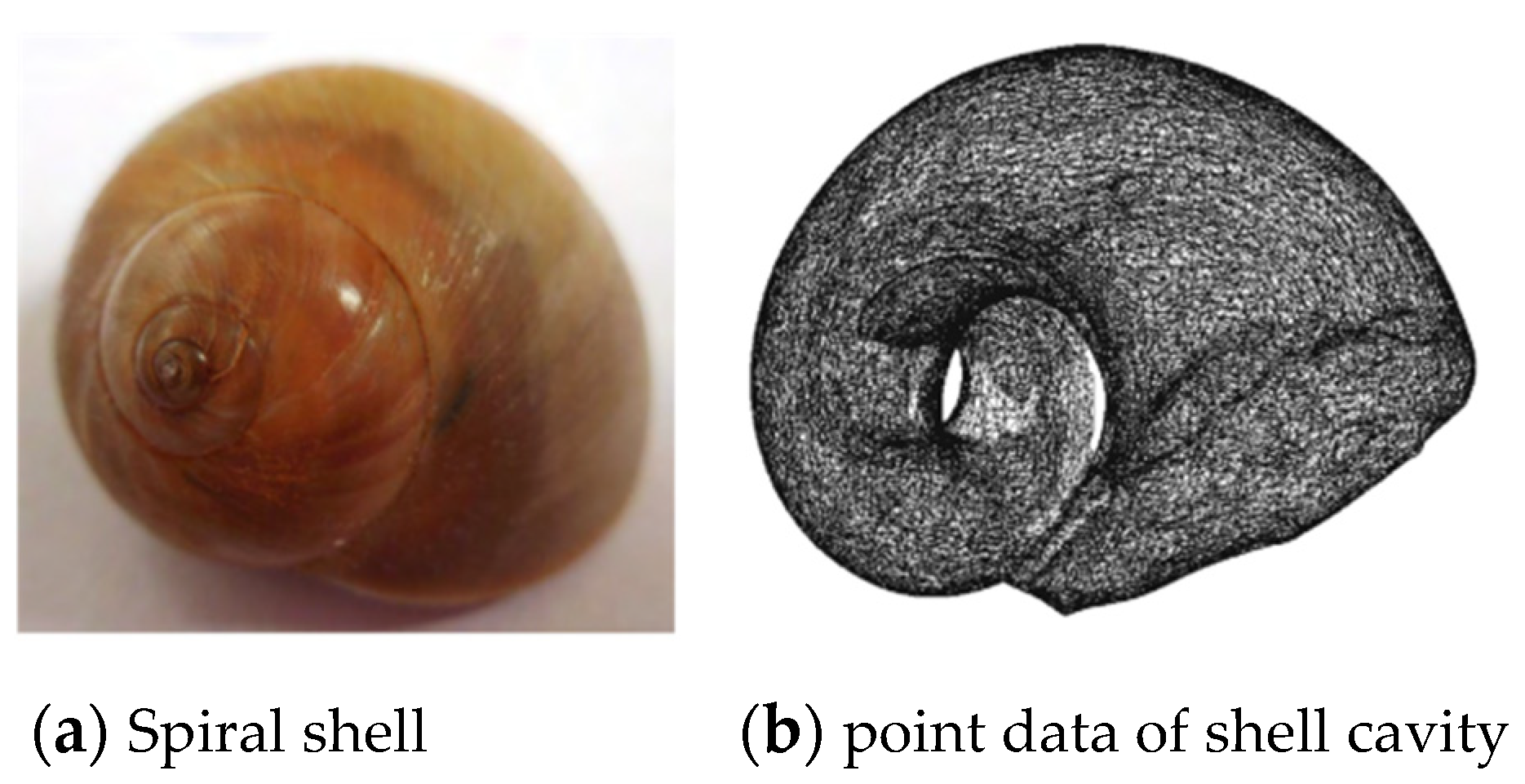
The characteristics of reducing fluid resistance and energy loss are evident during the evolution of marine spiral shells [35]. With the continuous improvement of digital measurement technology in reverse engineering, the design of the bionic snail shell is made through the processing of point cloud data [36] and then uses the least square method to complete the curve mathematical modeling [37], where the curve mathematical model is:
X i = 8.77 cos θ , Y i = 7.09 sin θ , θ [ 0 . 2 π , 0 . 56 π ] ,
where X is the long axis of the point cloud fitting curve, and Y is the short axis of the point cloud fitting curve.
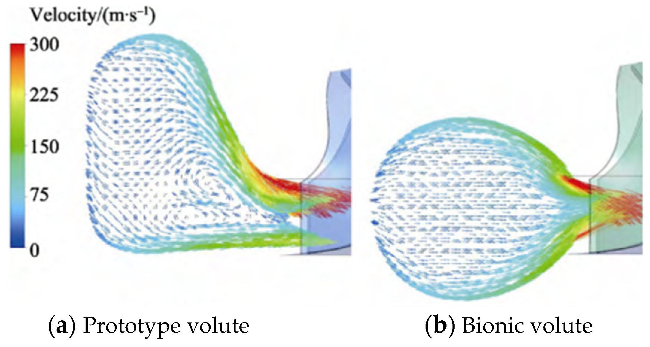
The simulation results show that the airflow inside the bionic volute flow channel flows regularly to the outlet nozzle of the volute and is symmetrically distributed up and down. The flow direction of the airflow is more consistent, and the airflow enters the impeller flow channel more smoothly, which is conducive to reducing the pressure pulsation of the volute to achieve the effect of noise reduction. The geometry of the bionic spiral shell tongue and the result are shown in Figure 5 and Figure 6.
Snail shell and spacer noise reduction study are shown in Table 1.
Based on the studies, it is found that the bionic tongue can rectify the airflow on the surface of the tongue, make the airflow velocity distribution on the surface uniform, and reduce the influence of airflow on the outlet [38]. The bionic volute tongue can effectively inhibit the turbulence intensity in the flow field on the volute tongue surface and to a large extent reduce the influence of airflow on the volute tongue, thereby reducing or delaying the generation of shedding vortex. The pressure pulsation intensity of the turbulent boundary layer on the volute tongue surface is reduced, thereby reducing the airflow noise generated by the turbulence on the volute tongue surface at the outlet of the fan [39].
At present, all the kinds of bionic volute tongues have not reached the level of theoretical research at the application level, and the accuracy of processing and manufacturing has difficulty meeting the requirements. The shape of all kinds of bionic worm tongues is still in the research and development stage. There is no clear research direction for the bionic worm tongue structure with a better noise reduction effect. Therefore, we should summarize the bionic worm tongue with obvious noise reduction and easy processing through experiments.
In summary, although the volute tongue is a common static component in fans, its size, shape, and parameter design play a crucial role in fan performance, especially aerodynamic performance and noise control. At present, high-accuracy bionic snail tongues are mostly laboratory experiments, which cannot be easily copied and machined.

3.2. Research on Noise Reduction of Bionic Blade Non-Smooth Surface

By exploring the anechoic noise reduction mechanism of the non-smooth form of the leading edge of the owl, the noise reduction information of the non-smooth surface of the leading edge of the long-eared owl was extracted and a non-smooth analogical model of the leading edge of the long-eared owl was established [40]. Using fluid dynamics (CFD) technology and the SST model, the SST k-ω model was developed by Menter to allow independence from the k-ε model in a wide range of fields; the classical acoustic method for solving the influence of the lighting acoustic analogy equation on the boundary of stationary solid was combined. The lighting acoustic analogy equation will be shown as follows [41]:
ρ ( x , t ) = 1 4 π c 0 2 2 x i x j v τ i j ( y , t R c 0 ) R d V ( y ) + x i s l j p i j ( y , t R c 0 ) R d S ( y )
where x is the acoustic observation point location vectors, y is the location coordinates of sound source points, and l j is the unit normal vector of the solid boundary surface. The first term of Equation (2) is the volume fraction, representing the quadrupole stress source, and the second term is the area fraction, representing the dipole source. That is, sound analogy theory divides the analysis of airflow noise into two steps: the first step is the generation of sound, where the source is induced by flow in an arbitrary continuous medium, and the source term can be obtained by calculating the non-constant winding field of the object; the second step is the propagation of sound in the medium, which can be obtained by solving the FW-H equation, which integrates the effects of solid boundaries and object motion on fluid-induced sound. The comparison of the simulation results is shown in Figure 7.
It shows that compared with the traditional smooth surface, the velocity distribution on the surface of the bionic non-smooth airfoil is more uniform, and the velocity change is more gentle, which reduces the pressure fluctuation intensity of the turbulent boundary layer on the airfoil surface, improves the stability of the boundary layer, and finally, reduces the airflow noise generated by the pressure fluctuation of the airfoil boundary layer.
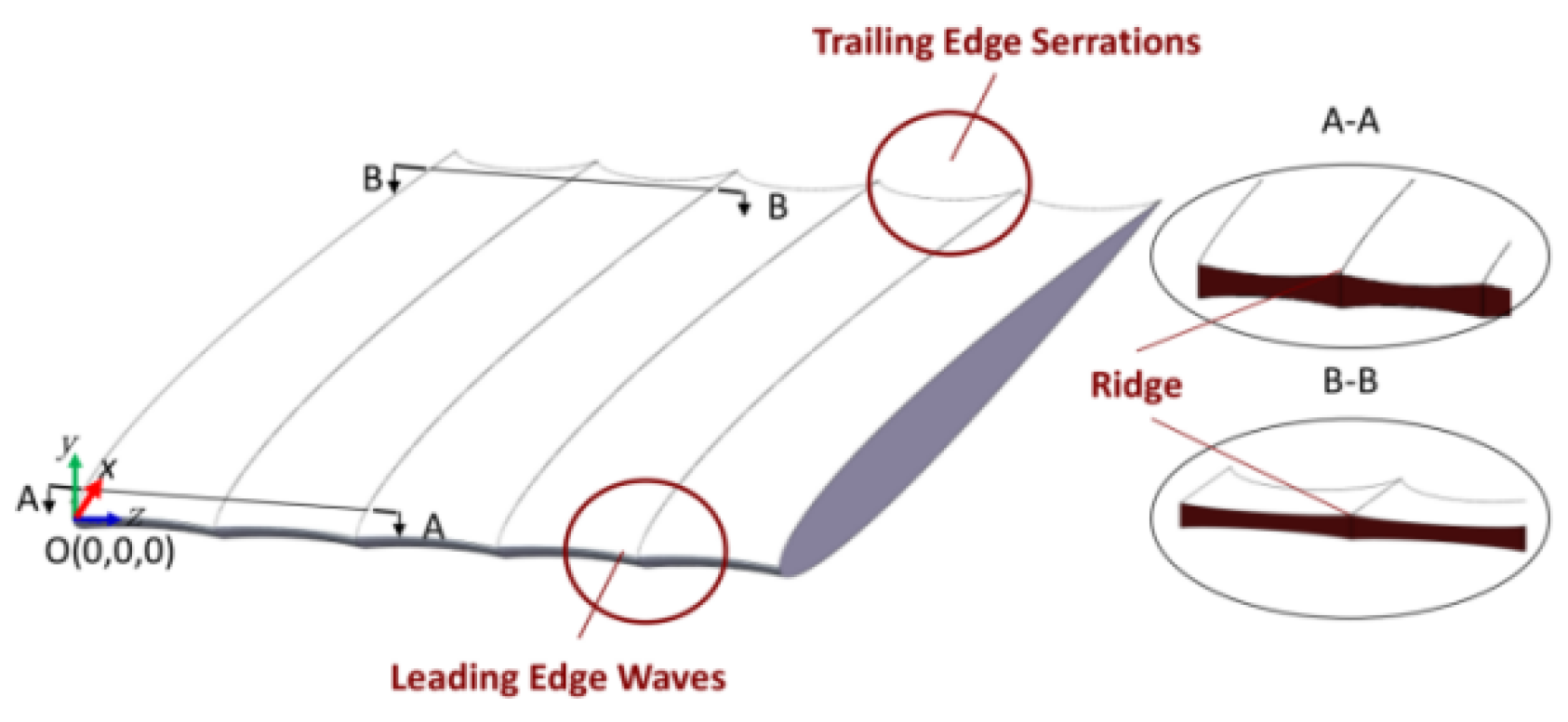
In a study to explore the bionic flow control noise reduction mechanism of thin airfoil blades, a bionic blade with ridged surface features [42] based on a composite bionic concept was designed. According to the sound pressure expression of dipole source with turbulent noise developed by Howe [43]:
P d ( X , t ) X i 4 π c 0 X 2 t [ F i + ρ 0 Δ d U i d t ] t = X c 0 , X ,
where ρ 0 is the density of fluids, F i is the force of the pulsation pressure that is imposed on the boundary of the solid wall, and the expression is:
F i ( t ) = S P i j ( y , t ) d S j ( y ) ,
It is found that in the adjacent ridge pattern, the reverse velocity of the airflow on the suction side in the wingspan direction is higher, and at the same time, under the reflection of the bionic blade valley wall, a higher normal velocity is generated. The geometry of a bionic blade is shown in Figure 8.
The transition speed of the boundary layer is accelerated, and the pressure pulsation caused by instability is reduced. The ridged surface on the pressure side makes the boundary layer more stable, reduces the unstable vortex formed by the boundary layer in the transition process, and accelerates the evolution and shedding of the laminar boundary layer near the trailing edge to the turbulent boundary layer.
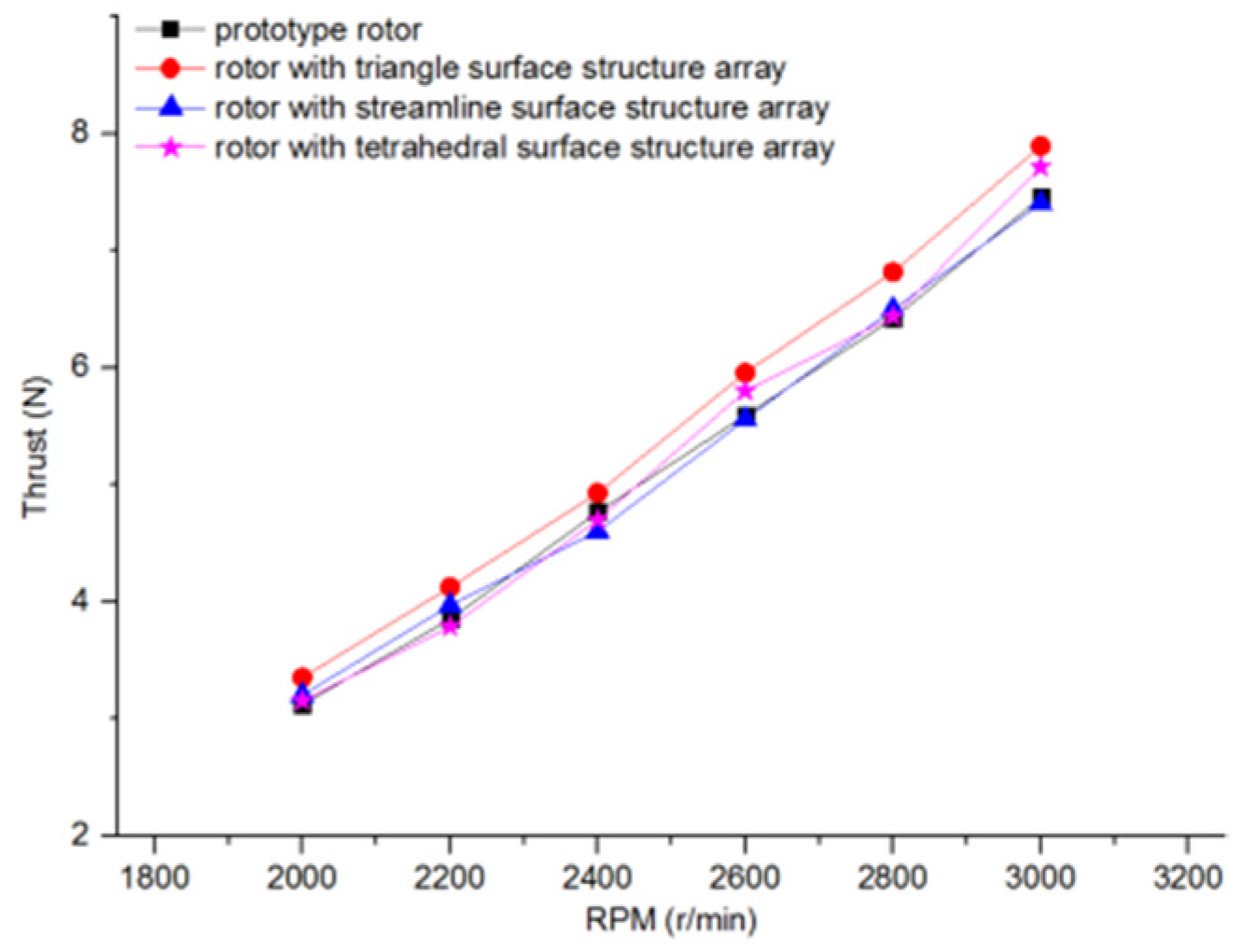
Inspired by the raised array structure on the surface of an owl’s wing, a raised array structure was added to the tail of the lower surface of the rotor to investigate the effect of this raised array structure on the performance of the rotor [44]. The parameters of the prototype rotor are shown in Figure 9.
The simulation result is shown in Figure 10.
Compared with the prototype wing manufactured by 3D printing, the experimental results showed that the lower surface bulge structure can provide a certain adhesion to the airflow, increase the pressure, delay the shedding of the surface airflow, increase the eddy current at the surface bulge structure, and improve the aerodynamic performance of the rotor. Under the same lift, the rotor speed was reduced to achieve the effect of noise reduction.
With the surface features of shark skin receiving more attention, the surface features of shark skin were extracted, and a centrifugal fan model with a V-groove surface bionic blade was built [45]. The shear stress transfer k ω turbulence model was used to numerically simulate the internal flow field of the bionic centrifugal pump. The expression of the drag reduction rate is:
C = [ ( N s - N r ) / N r ] × 100 % ,
where N s is smooth-surface impeller torque and N r is bionic surface impeller torque.
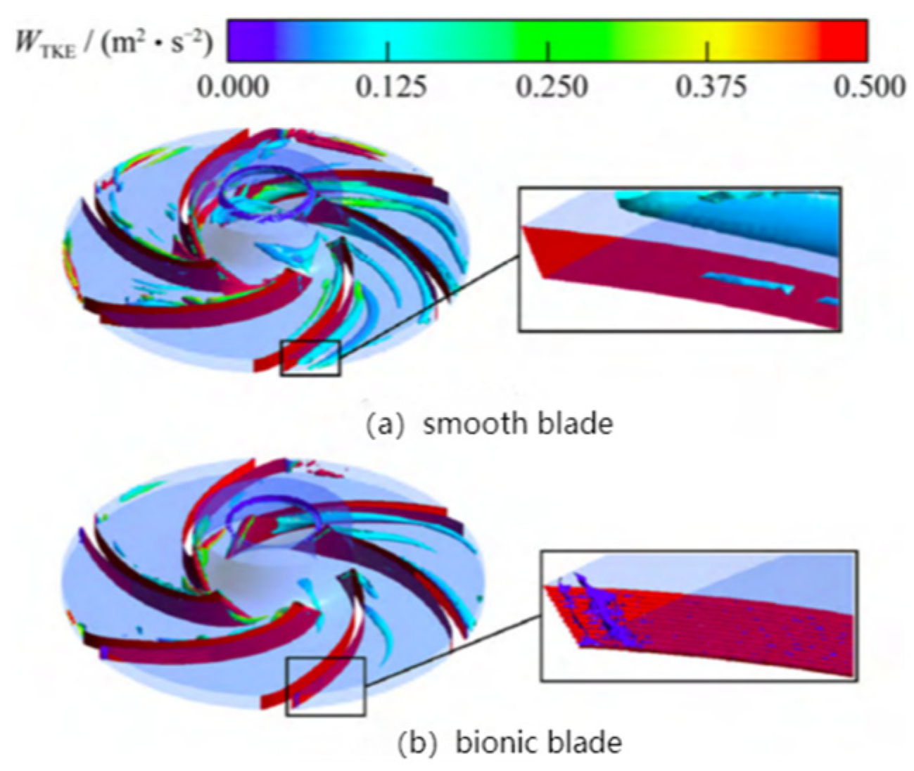
The V-groove surface bionic vane can effectively control the fluid flow near the wall of the vane [46], which reduces the wall shear stress at the outlet and changes the vortex structure in the impeller flow channel, thus reducing the internal turbulence of this centrifugal fan and thus achieving a noise reduction effect. A comparison of the two results is shown in Figure 11.
Noise reduction studies on non-smooth surfaces is shown in Table 2.
The bionic non-smooth surface vanes improve the flow state of the fluid near the wall, which results in a reduction in near-wall viscous drag and Reynolds stress and, consequently, a reduction in shear stress at the wall. As the turbulence on the surface of the bionic blade decreases, the contact area in the wake area decreases and the surface tangential drag on the bionic blade decreases; the bionic non-smooth blade can have a certain noise reduction effect on noise. The study of bionic non-smooth blades has not only had a significant effect on noise reduction but has also made an outstanding contribution to drag reduction. However, there is usually a significant distinction between different prototypes of bionic blades in terms of their ability to suppress and control noise in different frequency bands. The design of a non-smooth bionic blade requires the parallel design of multiple parameters such as Reynolds number, angle of attack size, blade size, and fluid flow size at the same time.

3.3. Research on Noise Reduction of Leading-Edge Bionic Blades
Given that most of the centrifugal fan blade bionic noise reduction optimization has been inspired by the design of previous generations in the independent airfoil type for a long time. Therefore, there is a gradual transition from the existing bionic optimization of stand-alone airfoils to the design of blade bionic noise-reduction optimization in centrifugal fans.
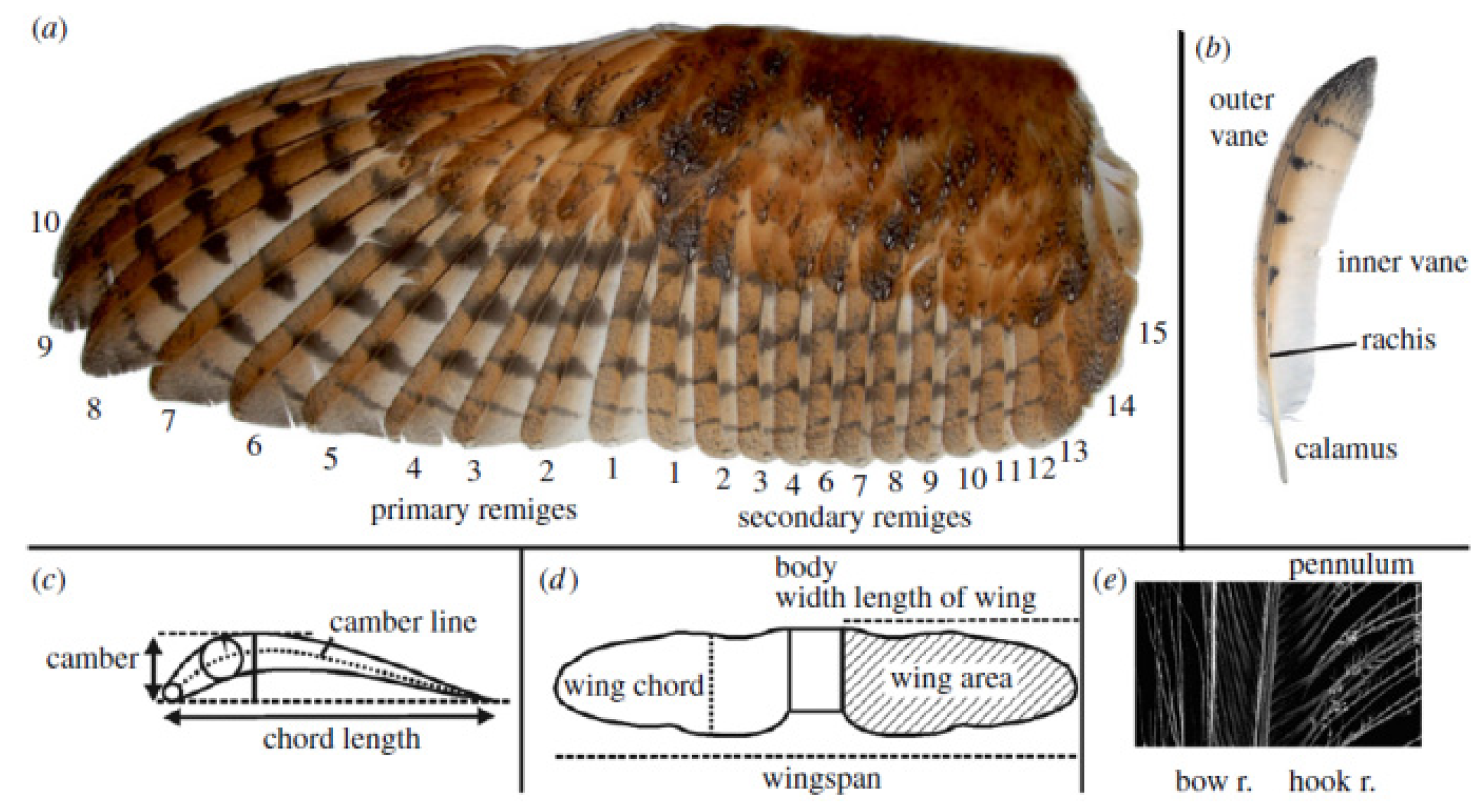
The research on the bionic leading edge of blades primarily began in the 1970s. Hersh [47,48] first published the research results of noise reduction of blades modified according to the comb structure of the leading edge of owl wings (Figure 12).
They designed the serrated leading edge structure to reduce the noise of the propeller and wing, and experimental measurements show that the serrated leading edge structure can reduce noise by 4–5 dB [49].
Thereafter, the noise-reduction effects of the comb teeth at the leading edge of the NACA0012 and two-bladed propeller were compared respectively, and the noise reduction mechanism of the leading edge of the comb tooth shape was also analyzed. They concluded that the leading edge of the comb-tooth shape generates a vortex at the trailing edge, which can reduce the vortex shedding noise by interfering with the frequency of the trailing vortex shedding [50,51].
A comparison of the wing and feather structures of low-noise flying owls with those of fishing owls without the ability to fly low noise shows that the comb structure of the leading edge of the feathers of low-noise flying owls (Figure 13) and the soft down on the surface were the main reasons for their quiet flight [52,53,54].
Thereafter, the leading-edge comb structure of the grey forest owl was studied for its effect on flight noise, and it was found that the leading-edge comb structure has a certain noise reduction effect at frequencies less than 800 Hz [55].
With the increasing popularity of wind tunnel experimental equipment and its ability to provide a wider range of basic information, it is widely used in wind experiments [56,57].
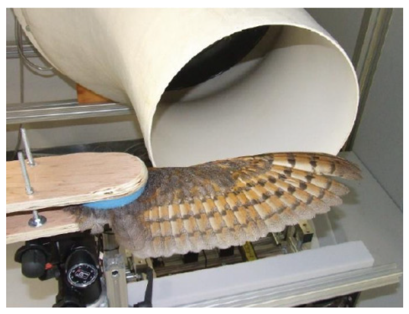
Wind tunnel tests in the interior have confirmed more rigorously the low-noise performance of owl fins compared to other bird fins [58,59]. The installation of the experimental wing is shown in Figure 14.
The results show that when the airflow is 15 m/s, the noise generated by the wings of the pale owl and tawny owl is much less than the noise generated by the wings of the sparrowhawk and pigeon at the same frequency.
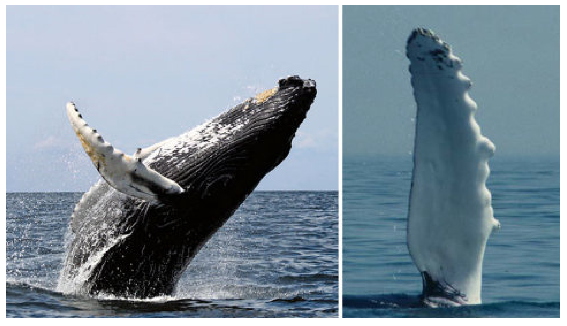
In recent years, for the noise reduction at the leading edge of blades, people gradually focus on the imitation of the leading edge bulge structure of humpback whale flippers (Figure 15) [60,61], leading to the quantitative characterization of the hydrodynamic shape of the humpback whale’s flipper limb by reverse engineering methods, the construction of a three-dimensional model of the flipper limb’s anterior edge in combination with knowledge of the raised nodes on the limb’s anterior edge, and further discussion on the functions of the nodules at the leading edge of the flippers [62,63].
To further determine the flow field control performance of the leading-edge bulge structure, noise-reduction studies based on humpback whale flippers with bionic leading-edge blades were first applied to a range of wing types such as NACA [64,65].
Figure 15. Spherical knots on the flippers of humpback whales [66].
Energies 16 04331 g015
A fin-like blade based on the NACA0020 airfoil was manufactured to compare the aerodynamic performance of the smooth leading-edge structural model with that of the raised leading-edge structural model [66,67,68]. The test results show that when the Reynolds number of the average chord length is about 5 × 10⁵, the stall angle of the leading-edge nodule of the flipper can be increased by 40% on the premise of reducing drag and increasing lift.
These conclusions encourage people to study the aerodynamic and acoustic performance of airfoil blade leading-edge raised structure from various angles, which can effectively improve the aerodynamic and acoustic performance of rotating machinery.
To reduce the interference noise, the sinusoidal wave structure was applied to the sNACA651210 airfoil, and through experimental comparison, it was found that in the experimental velocity range, compared with the NACA651210 independent airfoil, the sinusoidal wave structure can effectively reduce the turbulence-airfoil interference noise by 3~4 dB [69].
To further explore in depth the effect of blade leading edges on interference noise, the effect of the undulating leading edge on the turbulent-airfoil (flat plate) leading-edge interference broadband noise was investigated [70,71]. The results showed that the wave-like amplitude of the wave-like front was a key parameter affecting noise reduction, while the period of the wavefront had a weak effect on noise reduction. As the wave amplitude increased, the noise reduction effect also increased. The comparison of results is shown in Figure 16.
At the same time, the leading-edge bionic treatment is applied to the fan. Through numerical simulation, the trend relationship between the velocity pulsation at the tip of the trailing-edge blade and the leading-edge bionic treatment is given. It can be seen that the velocity pulsation amplitude of the trailing edge of the bionic leaves decreased significantly, but there was little difference in frequency [72].
The effective control of turbulent interference noise is achieved by bionic structures in the optimal design of NACA airfoils [73]. The centrifugal fan adopts a common NACA blade shape (Figure 17), and the bionic strategy is to use the sinusoidal distribution of the entire blade leading edge to approximate the bionic effect [74,75].
The bionic treatment of the leading edge of the blade does not affect the flow field at the span 50% position of the middle section, but the bionic leading-edge blade has a good inhibitory effect on the large separation vortex near the span 90% position of the upper cover. The result of the Vorticity contours is shown in Figure 18.
To investigate in more depth the effect of bionic structures on the control of turbulent low-frequency noise, the application of sinusoidal leading edge modes is used in the axial fan blades [76,77]. The experimental device is shown in Figure 19.
Their research showed that in the high-frequency noise environment, the difference in noise-reduction effect between the two is not obvious, and in the low-frequency condition, the average total sound pressure of the sinusoidal front fan is about 1dB lower than that of the straight front fan. With the increase in volume flow rate, the maximum mean total sound pressure difference between the two can reach 1.8 dB [78].
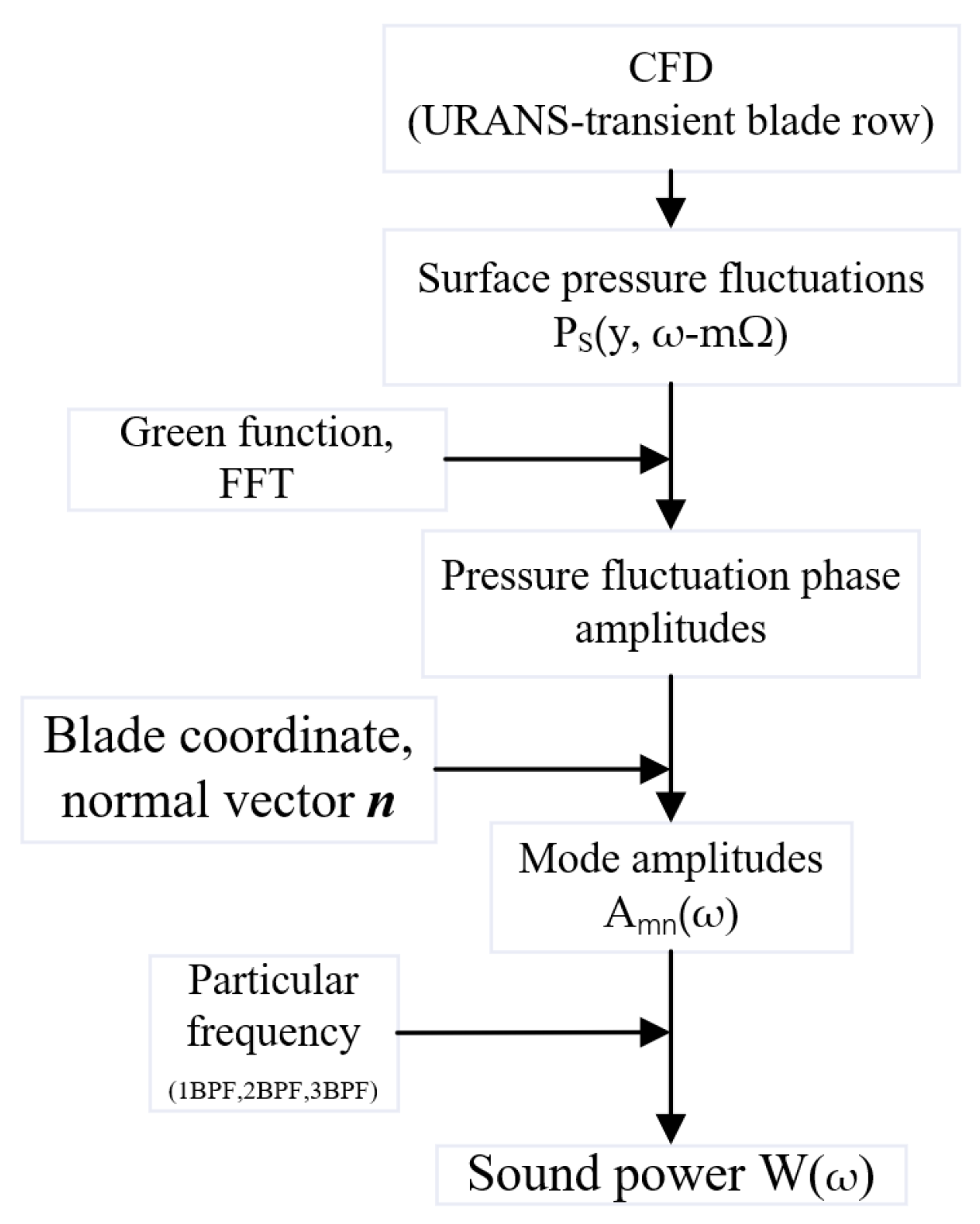
To explore the application prospects of the wave leading-edge static sub-blade in large impeller machinery noise reduction, the noise-reduction effect of the reference static sub-blade and three wave leading edge static sub-blades were numerically simulated by using the hybrid method of URANS and the FW-H equation [79,80]. The computational steps of the tonal noise hybrid method are shown in Figure 20.
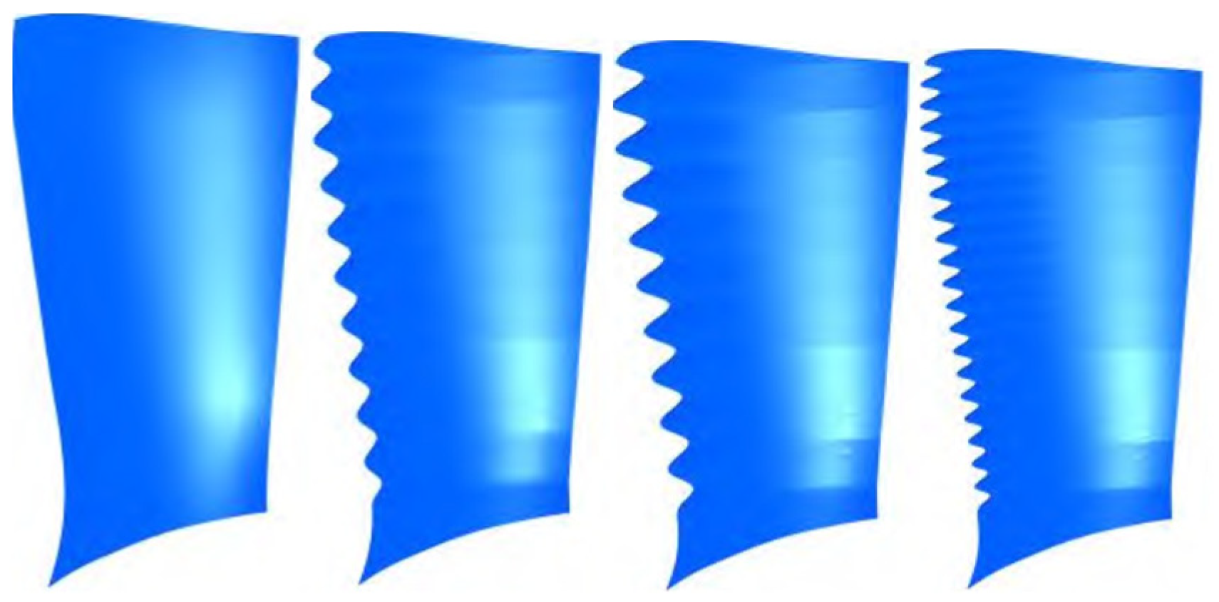
The results show that, compared with the reference static blades, the three static blades at the wavefront can effectively reduce the sound power level at the fan inlet. They believe that the benchmark static blades at the wavefront can reduce the noise intensity by changing the relationship between the amplitude and phase of pressure pulsation on the blade surface, and the increase in amplitude will reduce the sound source intensity. However, the noise reduction method of changing the phase relationship of the sound source needs to take both radial mode and wavelength into account [81]. Figure 21 and Figure 22 show the blade models.
Although a wavy leading edge is the mainstream direction at present, there are still some scholars studying the noise reduction performance and application of a serrated front [82,83,84].
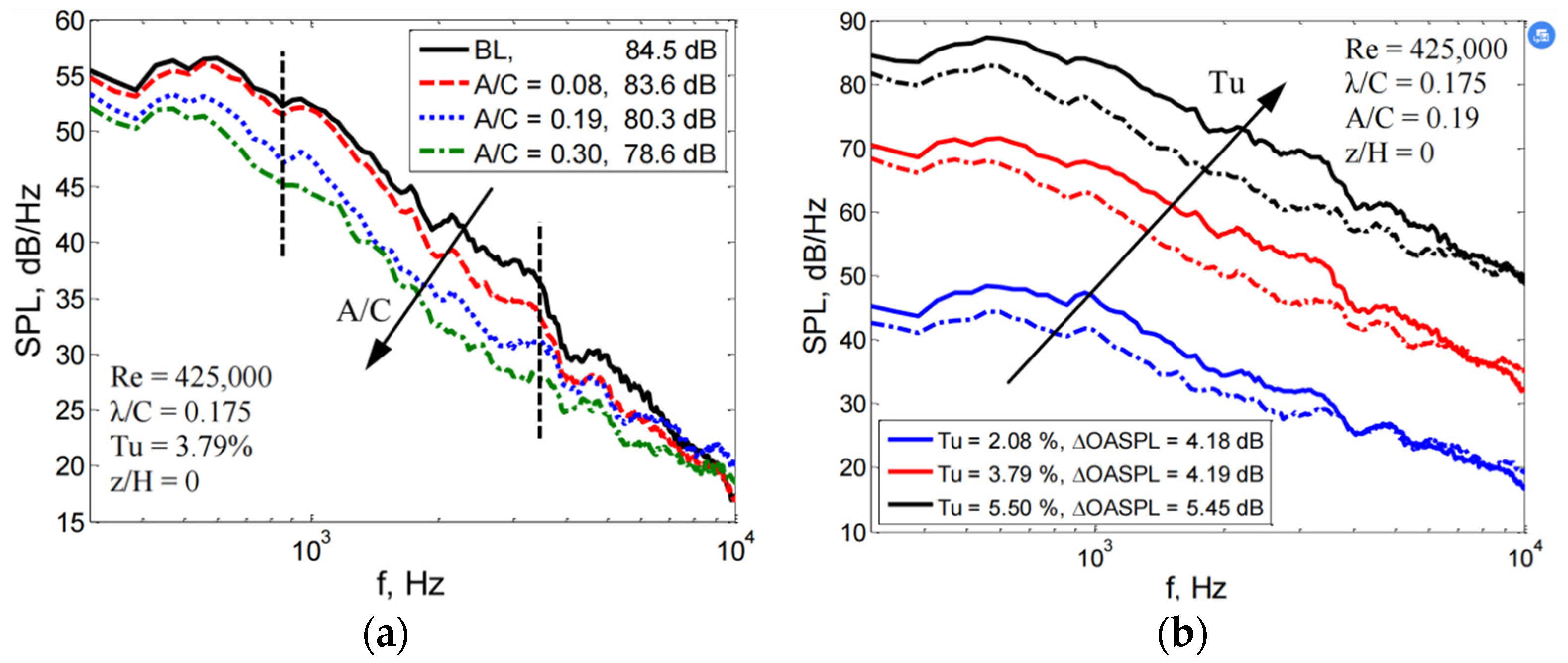
To explore the effect of sawtooth amplitude on the noise reduction performance of fans, it was found that with the increase in sawtooth amplitude, the reduction amount in hydrodynamic noise first decreased and then increased, and with the decrease in wavelength, the reduction amount in hydrodynamic noise kept increasing through the experiments [85].
The sawtooth leading-edge model with an amplitude of 0.025 c and wavelength of 0.05 h has the best noise-reduction effect, and the total radiated sound power level of reducing hydrodynamic noise reaches 10.19 dB, as shown in Figure 23.
The results show that the leading edge of the sawtooth can weaken the strength of the horseshoe vortex at the source and the running path to reduce the hydrodynamic noise of the volute caused by the horseshoe vortex.
Noise-reduction studies on the bionic leading blade is shown in Table 3.
From existing bionic front research results and the development process of pneumatic noise control technology in bionics over the past 10 years [86], the bionic leading edge can effectively reduce the noise generated by blade operation, make the blade surface flow smoothly, reduce the pressure pulsation amplitude of the turbulent boundary layer, effectively delay the separation of airfoil around the boundary layer of the flow field, reduce the generation of sound energy, and then reduce or delay the generation of the vortex on the blade surface to reduce the influence of falling vortex noise.
Bionic flow control is a frontier field of fluid mechanics research, which is widely of concern by domestic researchers, but it is not mature in principle and technology. The bionic flow control method also has very good flow field control efficiency under certain conditions by imitating different creatures or biological structures, such as owl feather characteristics and humpback whale flipper protruding structure.
The use of bionic structures to parameterize and adjust the leading-edge configuration for noise control is also one of the main methods of noise reduction. The results of many types of research have shown that the bionic design of the wavy or serrated leading edge structure has a significant effect on the noise control of low Reynolds number and the small angle of attack of turbulent flows in impellers. The unstable T-S waves in the boundary layer are suppressed by accelerating the energy exchange in the boundary layer employing a bionic wavy leading edge, which cuts off the acoustic feedback loop of interference noise between the T-S wave and the trailing edge, resulting in a reduction in leading-edge blade noise. However, at high Reynolds numbers and large angles of attack, the vortex volume of the bionic undulating leading edge will increase significantly, and the separation noise will be the main noise of the blade, and the undulating leading edge will separate earlier under this large angle of attack condition, and the noise-reduction effect is significantly reduced.
There is still a long way to go for the practical application of the bionic front, and there is still more research to be undertaken. At present, there have been a large number of studies in the bionic blade lift coefficient, drag coefficient and lift-to-drag ratio, sawtooth wavelength, and sawtooth amplitude change law. However, the use of the wave leading edge makes the blade aerodynamic performance and noise reduction effect to meet the design requirements at the same time still need to be studied.

3.4. Research on Noise Reduction in Trailing Edge Bionic Blades

Similar to the leading edge, the trailing edge of the centrifugal fan is also inspired by a large number of independent airfoils for noise-reduction optimization. Therefore, the trailing-edge bionic noise reduction in centrifugal fan blades is also gradually transitioned from the early independent airfoil optimization to the blade bionic optimization of centrifugal fans.
Since the 1990s, people have been inspired by three unique soft wing structure characteristics of owls, namely, the serrated leading edge, serrated trailing edge, and velvety surface, which can effectively suppress the aerodynamic noise under the turbulence model of a low Reynolds number [87].
It is based on the understanding of the ecological structure of the owl’s silent flight ability that the noise-reduction design mimicking the trailing-edge structure of the owl’s wing was born and developed [88]. Among them, the use of a serrated structure in the practice of blade trailing-edge noise reduction has achieved remarkable results and is widely regarded as the most effective method [89].
The research on the bionic airfoil with a serrated trailing edge was first started in 1991. Howe found that the efficiency of interference noise radiation between the gust with a wave number perpendicular to the trailing edge was higher than that of the tilted gust, and the serrated trailing edge, because of the structure of the tilted trailing edge, had noise reduction ability [90].
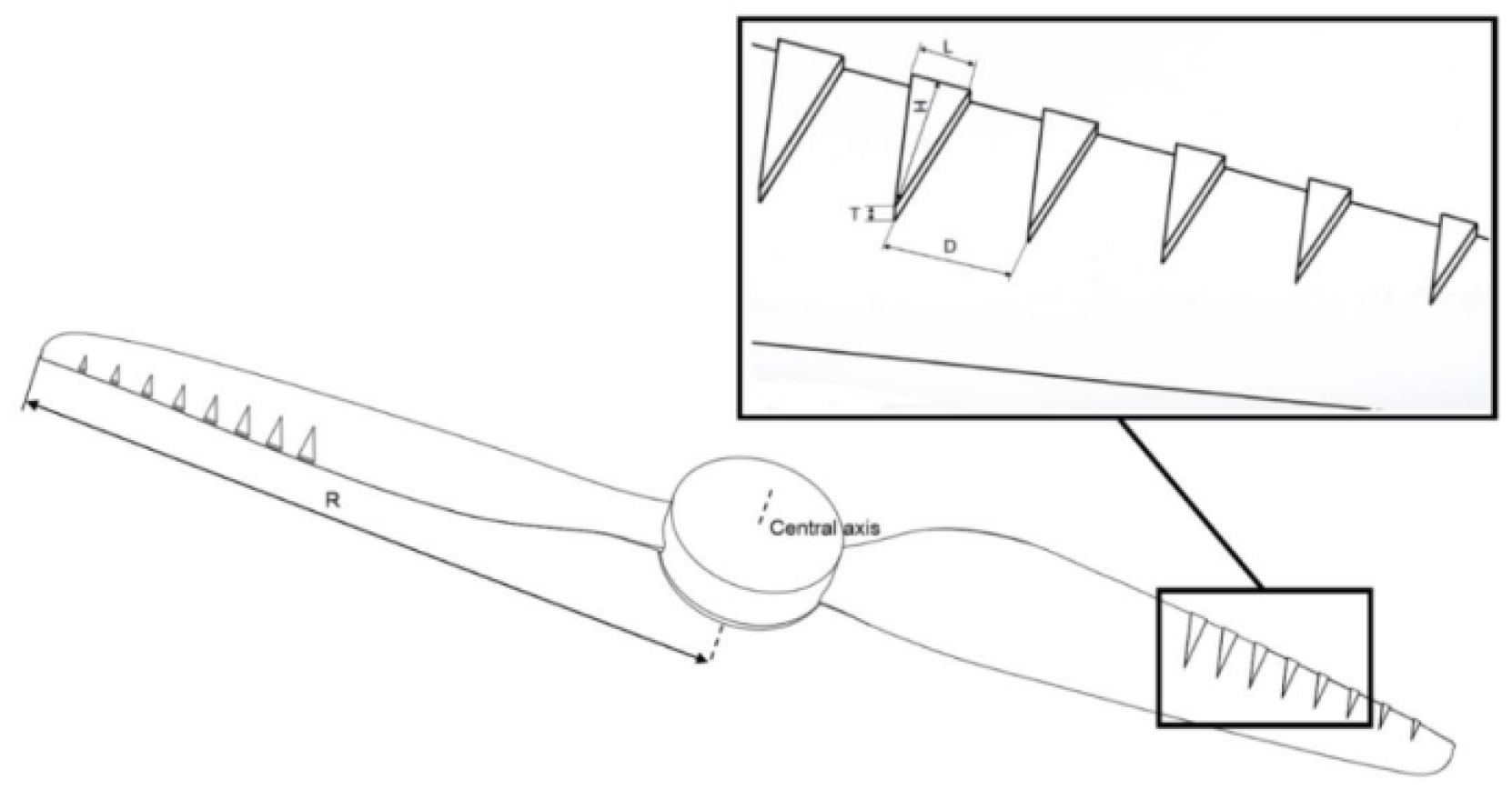
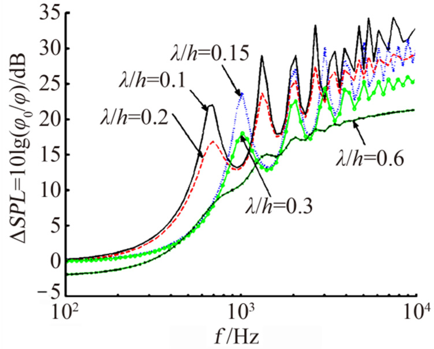
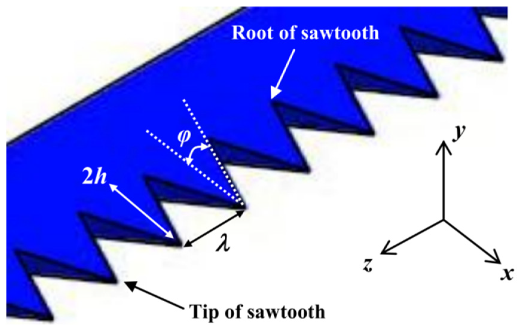
On this basis, Howe [91,92,93] predicted and analyzed the noise reduction value of a flat airfoil with a serrated trailing edge when the angle of attack was 0 at low turbulence. He assumes that the sawtooth spacing is λ and the height is 2 h, as shown in Figure 24, and the noise reduction is at least 10 log 10 1 + ( 4 h / λ ) 2 dB when the sound frequency meets ω h / U 1 .
According to this formula, the necessary condition for obtaining a more remarkable noise reduction effect is that the angle between the teeth meets the conditions θ 45 . Figure 24 shows the prediction results.
The two-dimensional airfoil with a tiny serrated trailing edge and the flat plate with a tiny serrated trailing edge were subjected to noise development experiments utilizing acoustic wind-tunnel equipment. They found that all airfoils with serrated trailing edges reduced noise by 3 to 8 dB, while plates with serrated trailing edges reduced noise by up to 10 dB [94].
With the development of numerical simulation technology and the improvement of computer capability, the simulation of the acoustic performance of bionic trailing-edge blades through computer simulation is favored by more and more scholars and engineers [95]. With the increase in computing capability, engineers can calculate more complex surface structures and finer mesh-size geometries, capturing even smaller vortex structures.
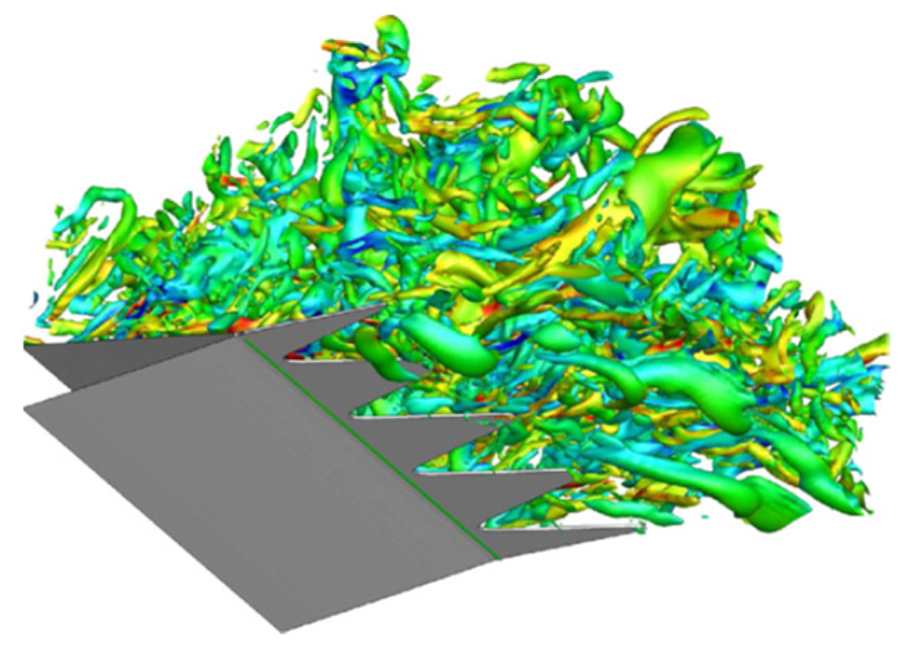
To investigate the effect of Reynolds number on the turbulence noise of a trailing edge with a serrated airfoil, a numerical analysis of the trailing edge with a serrated airfoil was carried out by direct simulation (DNS) at low Reynolds numbers [96]. It is found that long and sharp serrated teeth have a better noise reduction effect than short serrated teeth. At the same time, they pointed out that the serrated trailing edge could not significantly change the flow characteristics of the blade surface upstream of the trailing edge, such as Reynolds stress, turbulence spectrum, and span-wise coherence, which indicated that the reduction in trailing edge noise was only caused by changes in the acoustic scattering process itself and the local flow field in the zigzag region (Figure 25).
They believe that the mechanism of noise reduction at the trailing edge of the serrated structure lies in the large number of horseshoe vortexes generated by the serrated structure, which promote the mixing of wakes and, thus, reduce the span coherence in the trailing-edge region.
To investigate the effect of the serrated trailing edge on noise control in the low-frequency range, the NACA65 micro-curved blade trailing edge was selected [97]. The results show that the serrated trailing edge effectively reduces the trailing-edge noise in the low-frequency range, up to 10 dB, but increases the trailing-edge noise in the high-frequency range. They believe that the influence of the serrated trailing-edge structure on the flow near the trailing edge is the main reason for noise reduction. The serrated structure produces a strong and complex vortex flow phenomenon near the trailing edge and reduces the span-wise coherence near the trailing edge.
In addition to the commonly applied planar cut-in airfoil trailing edge, an attempt to use a non-planar, serrated trailing edge to control turbulence noise has also received attention [98], and experiments and simulations have been conducted to compare the effectiveness of different sizes of teeth in suppressing vortex shedding noise [99]. The geometry of the blade is shown in Figure 26.
The experimental results show that these holes’ serrated trailing edges are not only effective in reducing noise but also have an additional advantage over flat-type serrated trailing edges, providing a minimal increase in noise at high frequencies. The value of achieving low fan noise in the industry is enormous.
To study the effect of turbulence intensity on the noise-reduction effect of the trailing edge of the blade and to compare the ability of the leading edge and trailing edge to suppress noise under the same conditions, the aerodynamic noise of the airfoil conventional trailing edge and the serrated trailing edge was studied by using a planar microphone array [100]. The geometry of the three blades is shown in Figure 27.
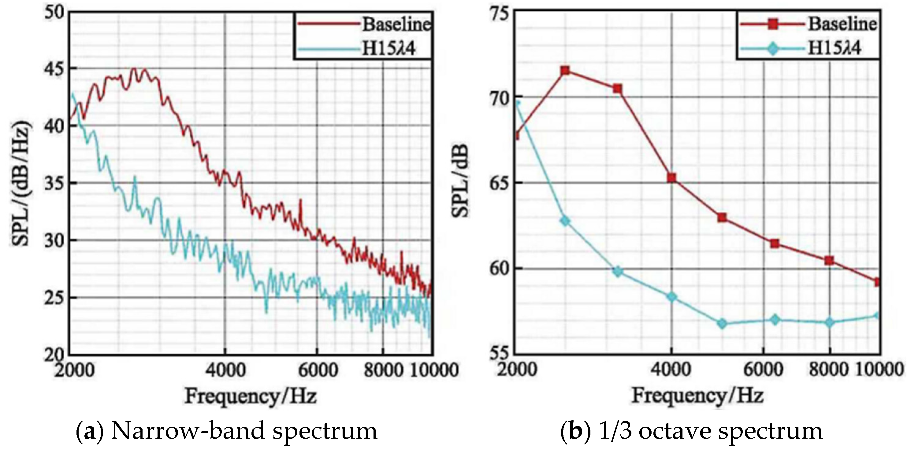
The experimental results show that the trailing-edge noise exceeds the leading-edge noise in the case of low turbidity and free inflow, which is the main source of airfoil noise. The noise-reduction effect of the sawtooth trailing edge at low frequency is much better than that at medium and high frequency (Figure 28).
Although serrated noise reduction is the most effective, there are still many who are looking for a different direction from a breakthrough [101]. Although it has not yet been tried on centrifugal fans, finned nodular trailing edges have been used in centrifugal pumps for the first time [102].
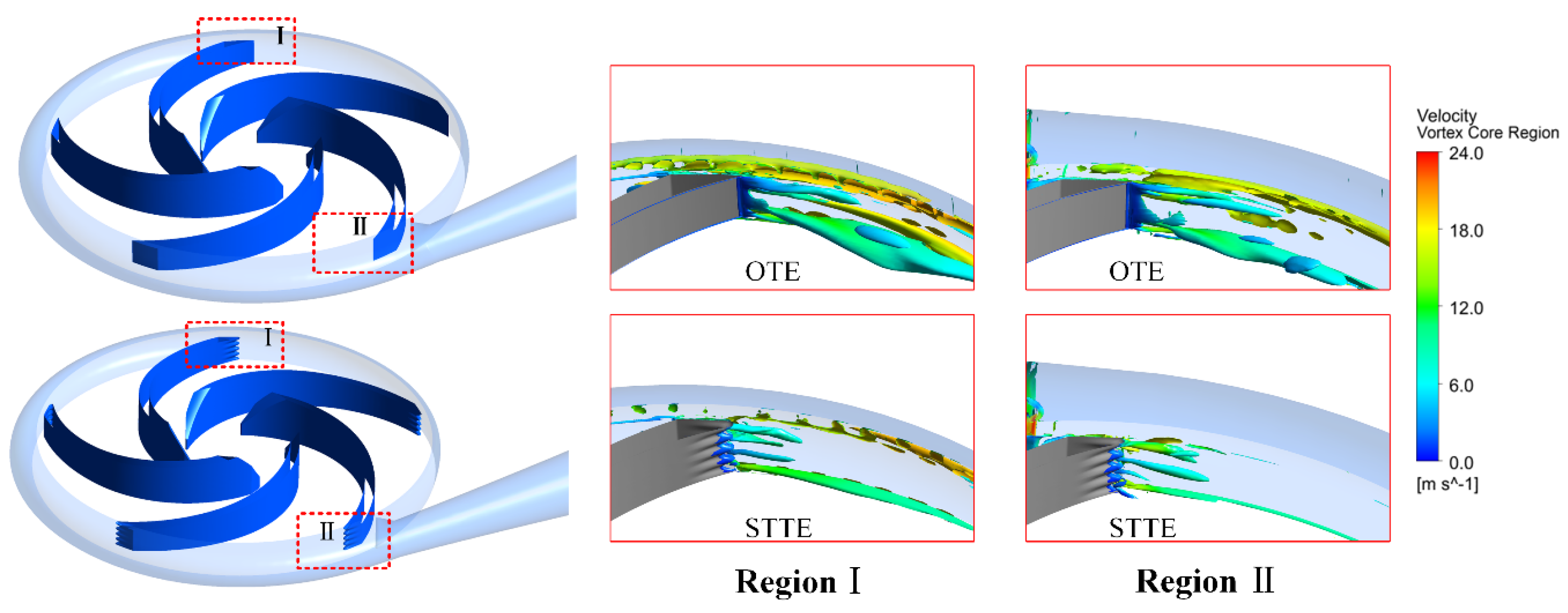
In the tongue of the volute, the pressure pulsation amplitude of STTE at the single octave band pass filter is significantly reduced. The result is shown in Figure 29.
The STTE impeller also effectively changes the vortex structure and strength in the trailing-edge region of the blade, which is of great significance for the optimal design of the pump.
Noise-reduction studies on the bionic trailing blade is shown in Table 4.
As a result of these studies, the trailing edge of the blade is the region where the air and vortex dynamics of the critical layer change the most. At the trailing edge of the blade, the critical layer of air loses the squeeze push of the blade, reducing the pressure and changing the magnitude and direction of the velocity; this change in pressure and velocity produces aerodynamic noise. The serrated structure of the trailing edge of the blade makes the above process slow and discontinuous, changing the dislodging position of each section of the wake vortex and increasing the distance between vortexes, reducing the disturbance of the wake flow by dislodging the vortex and decreasing the pressure pulsation on the blade surface, which eventually makes the aerodynamic noise caused by the wake vortex significantly reduced. The reduction in vortex break-up and the disturbance pressure of the critical layer of air reduces aerodynamic noise. However, sawtooth trailing edges, for example, increase the number of small vortex structures in their trails, which can lead to higher surge noise, especially in the high-frequency band, due to the surge in the number of small vortex structures.
Despite a great number of studies, the noise reduction mechanism of the trailing edge bionic configuration is still not thoroughly developed and has not reached a uniform understanding, and no uniform guiding law has been given regarding the design of the trailing-edge serrations. Similar to trailing-edge noise-reduction studies, the complexity of the turbulence problem itself, and the fact that the bionic configuration often involves very small-scale turbulence details and sound generation processes, makes the noise-reduction mechanism for trailing-edge bionic configurations still incomplete, a completely unified concept of the physical mechanisms by which wavy and serrated trailing edges influence the development of turbulence and the process of turbulent sound generation has also not yet been reached.

4. Conclusions and Outlook

This paper reviews and summarizes the research progress in the application of bionics in fan noise control technology from the perspective of existing bionics in fan aerodynamic noise reduction. It is not difficult to see that, despite nearly a century of exploration, there is still a significant gap in the practical engineering application of bionic noise-reduction theory. For example, in practical engineering applications, the physical mechanisms of the sawtooth trailing edge and wave leading edge to reduce unstable noise are missing. Therefore, the theory and practice of bionics in the control of aerodynamic noise in fans still need to be explored and researched.
The main source of aerodynamic noise from large centrifugal fans is volute tongue noise. As the air flows rapidly through the tongue of the worm, the surface layer of the tongue is gradually swirled off at the end of the tongue, and the noise at the airflow outlet will increase in a consequential way. Additionally, the pressure pulsations in its vicinity can also lead to an increase in noise from the worm tongue. Generally, the control principle of the bionic noise-reduction worm tongue is to adjust the design parameters of the worm tongue around the surface layer to delay the separation time of the surface layer, thus successfully controlling the noise generation of the worm tongue.
At the application level, the microstructure or non-smooth projections of the bionic worm shell impose extremely stringent requirements on the processing of the worm shell. The cost of producing a worm shell that strictly meets the design requirements is often high, and it remains to be seen whether it can achieve the noise-reduction results of the simulation data. The level of theoretical research is much higher than that of experimentally designed products, and engineers are increasingly hungry for high-precision, easily machinable bionic snail shells.
At present, the theory of noise-reduction control for bionic non-smooth surfaces is still not clear enough, and the design of bionic noise reduction for different frequency bands still needs to be explored systematically. In addition, the microstructure of the blade surface or the array of non-smooth bumps have extremely demanding requirements on the processing of the blade, whether 3D printing or finishing, and it remains to be seen whether the finished product can achieve the noise-reduction effect of the simulation data results.
The bionic leading-edge configuration is often affected by the tiny size of the turbulent structure and its propagation process, and the noise-reduction mechanism of the bionic leading edge has not been studied in sufficient detail and thoroughness. In addition, when the angle of attack is too high, the noise-reduction effect of the leading edge of the wave decreases significantly to the extent that it gradually increases the trailing-edge noise. Neither wavy leading edges nor sawtooth leading edges affected by turbulence are uniformly understood at the physical level.
The application of the bionic structure to the trailing edge was developed and adjusted, which resulted in a more rapid shedding of the vortex structure, and made it finer and more fragmented. Especially in the low-frequency band, the method is effective in controlling the flow excitation noise. However, excessive trailing-edge serrations can cause a significant reduction in the efficiency and flow rate of the fan, which can have a considerable negative impact on fan performance. Therefore, whether the design of the trailing-edge serration type and size requires extensive experimental testing or the theoretical investigation of trailing-edge bionic design in the high-frequency band still needs to be explored.

Author Contributions

Conceptualization and design, P.Z., W.Z., C.X. and Y.W.; writing—manuscript preparation, P.Z., W.Z., J.M. and J.C.; writing—review and editing, P.Z., W.Z., Y.W. and J.C. All authors have read and agreed to the published version of the manuscript.

Funding

This research was funded by the Welfare Technology Applied Research Project of Zhejiang Province, grant number No. LGG21E090003, and the Welfare Technology Applied Research Project of Zhejiang Province, grant number No. 2022M712816, and the Zhejiang University Student Science and Technology Innovation Program and New Seedling Talent Program Project, grant number No. 2022R409A040.

Data Availability Statement

Not applicable.

Conflicts of Interest

The authors declare no conflict of interest.

References

  1. Han, Z.; Yin, W.; Zhang, J.; Jiang, J.; Niu, S.; Ren, L. Erosion-Resistant Surfaces Inspired by Tamarisk. J. Bionic Eng. 2013, 10, 479–487. [Google Scholar] [CrossRef]
  2. Chen, S.; Wang, D.; Sun, S. Bionic Fan Optimization Based on Taguchi Method. Eng. Appl. Comput. Fluid Mech. 2011, 5, 302–314. [Google Scholar] [CrossRef]
  3. Liu, X.; Liu, X. A Numerical Study of Aerodynamic Performance and Noise of a Bionic Airfoil Based on Owl Wing. Adv. Mech. Eng. 2014, 6, 859308. [Google Scholar] [CrossRef]
  4. Vincent, J.F.V.; Bogatyreva, O.A.; Bogatyrev, N.R.; Bowyer, A.; Pahl, A.-K. Biomimetics: Its Practice and Theory. J. R. Soc. Interface. 2006, 3, 471–482. [Google Scholar] [CrossRef] [PubMed]
  5. Marc, R.E.; Jones, B.W.; Watt, C.B.; Strettoi, E. Neural Remodeling in Retinal Degeneration. Prog. Retin. Eye Res. 2003, 22, 607–655. [Google Scholar] [CrossRef]
  6. Ballesteros-Tajadura, R.; Velarde-Suárez, S.; Hurtado, J. Noise Prediction of a Centrifugal Fan: Numerical Results and Experimental Validation. J. Fluid. Eng. 2008, 130. [Google Scholar] [CrossRef]
  7. Xu, Z.; Liu, X.; Liu, Y.; Qin, W.; Xi, G. Flow Control Mechanism of Blade Tip Bionic Grooves and Their Influence on Aerodynamic Performance and Noise of Multi-Blade Centrifugal Fan. Energies 2022, 15, 3431. [Google Scholar] [CrossRef]
  8. Wang, Z.; Han, F.; Ji, Y.; Li, W. Performance and Exergy Transfer Analysis of Heat Exchangers with Graphene Nanofluids in Seawater Source Marine Heat Pump System. Energies 2020, 13, 1762. [Google Scholar] [CrossRef]
  9. Zhou, S.; Dong, H.; Zhang, K.; Zhou, H.; Jin, W.; Wang, C. Optimal Design of Multi-Blade Centrifugal Fan Based on Partial Coherence Analysis. Proc. Inst. Mech. Eng. Part C J. Mech. Eng. Sci. 2022, 236, 894–907. [Google Scholar] [CrossRef]
  10. Velarde-Suarez, S.; Ballesteros-Tajadura, R.; Santolaria-Morros, C.; Pereiras-Garcia, B. Reduction of the Aerodynamic Tonal Noise of a Forward-Curved Centrifugal Fan by Modification of the Volute Tongue Geometry. Fluids Eng. Div. Summer Meet. 2005, 41995, 89–94. [Google Scholar] [CrossRef]
  11. Heo, S.; Cheong, C.; Kim, T.-H. Development of Low-Noise Centrifugal Fans for a Refrigerator Using Inclined S-Shaped Trailing Edge. Int. J. Refrig. 2011, 34, 2076–2091. [Google Scholar] [CrossRef]
  12. Chunxi, L.; Ling, W.S.; Yakui, J. The Performance of a Centrifugal Fan with Enlarged Impeller. Energy Convers. Manag. 2011, 52, 2902–2910. [Google Scholar] [CrossRef]
  13. Morris, S.C.; Good, J.J.; Foss, J.F. Velocity Measurements in the Wake of an Automotive Cooling Fan. Exp. Therm. Fluid Sci. 1998, 17, 100–106. [Google Scholar] [CrossRef]
  14. Mugridge, B.D.; Morfey, C.L. Sources of Noise in Axial Flow Fans. J. Acoust. Soc. Am. 1972, 51, 1411–1426. [Google Scholar] [CrossRef]
  15. Hersh, A.S.; Walker, B.E.; Celano, J.W. Helmholtz Resonator Impedance Model, Part 1: Nonlinear Behavior. AIAA J. 2003, 41, 795–808. [Google Scholar] [CrossRef]
  16. Fukano, T.; Kodama, Y.; Senoo, Y. Noise Generated by Low Pressure Axial Flow Fans, I: Modeling of the Turbulent Noise. J. Sound Vib. 1977, 50, 63–74. [Google Scholar] [CrossRef]
  17. Peng, L.X. On the Design Method of Noise Reduction of Centrifugal Fan. AMR 2012, 487, 520–524. [Google Scholar] [CrossRef]
  18. Khelladi, S.; Kouidri, S.; Bakir, F.; Rey, R. Predicting Tonal Noise from a High Rotational Speed Centrifugal Fan. J. Sound Vib. 2008, 313, 113–133. [Google Scholar] [CrossRef]
  19. Lauvstad, V.R.; Meecham, W.C. Acoustic Radiation from a Sinusoidally Rotating Circular Cylinder. J. Sound Vib. 1969, 10, 455–463. [Google Scholar] [CrossRef]
  20. Patri, A.; Patnaik, Y. Random Forest and Stochastic Gradient Tree Boosting Based Approach for the Prediction of Airfoil Self-Noise. Procedia Comput. Sci. 2015, 46, 109–121. [Google Scholar] [CrossRef]
  21. Ocker, C.; Geyer, T.F.; Czwielong, F.; Krömer, F.; Pannert, W.; Merkel, M.; Becker, S. Permeable Leading Edges for Airfoil and Fan Noise Reduction in Disturbed Inflow. AIAA J. 2021, 59, 4969–4986. [Google Scholar] [CrossRef]
  22. Makiya, S.; Inasawa, A.; Asai, M. Vortex Shedding and Noise Radiation from a Slat Trailing Edge. AIAA J. 2010, 48, 502–509. [Google Scholar] [CrossRef]
  23. Gelot, M.B.R.; Kim, J.W. Broadband Noise Prediction for Aerofoils with a Serrated Trailing Edge Based on Amiet’s Theory. J. Sound Vib. 2021, 512, 116352. [Google Scholar] [CrossRef]
  24. Guelich, J.F.; Bolleter, U. Pressure Pulsations in Centrifugal Pumps. J. Vib. Acoust. 1992, 114, 272–279. [Google Scholar] [CrossRef]
  25. Piwowarski, M.; Jakowski, D. Areas of Fan Research—A Review of the Literature in Terms of Improving Operating Efficiency and Reducing Noise Emissions. Energies 2023, 16, 1042. [Google Scholar] [CrossRef]
  26. Hao, W.; Wang, J.; He, X.; Zhu, Z.; Wang, Z.; Yang, H.; Zhang, W.; Wei, Y. Reduction of Aerodynamic Noise of Single-Inlet Centrifugal Fan with Inclined Volute Tongue. Meas. Control 2020, 53, 1376–1387. [Google Scholar] [CrossRef]
  27. Gu, Y.; Qi, D.; Mao, Y.; Wang, X. Theoretical and Experimental Studies on the Noise Control of Centrifugal Fans Combining Absorbing Liner and Inclined Tongue. Proc. Inst. Mech. Eng. Part A J. Power Energy 2011, 225, 789–801. [Google Scholar] [CrossRef]
  28. Xu, C.; Mao, Y. Experimental Investigation of Metal Foam for Controlling Centrifugal Fan Noise. Appl. Acoust. 2016, 104, 182–192. [Google Scholar] [CrossRef]
  29. Hayashi, I.; Kaneko, S. Pressure Pulsations in Piping System Excited by a Centrifugal Turbomachinery Taking the Damping Characteristics into Consideration. J. Fluids Struct. 2014, 45, 216–234. [Google Scholar] [CrossRef]
  30. Dieste, M.; Gabard, G. Random Particle Methods Applied to Broadband Fan Interaction Noise. J. Comput. Phys. 2012, 231, 8133–8151. [Google Scholar] [CrossRef]
  31. Guo, R.; Mi, T.; Li, L.; Luo, R. Research on Aerodynamic Performance and Noise Reduction of High-Voltage Fans on Fuel Cell Vehicles. Appl. Acoust. 2022, 186, 108454. [Google Scholar] [CrossRef]
  32. Liu, Y.; Yuan, Q.; Xu, Z.; Wu, L.; Liu, X. Bionic Volute Tongue Optimization Design of Multi-Blade Centrifugal Fan Inspired by the Wave Leading-Edge of Humpback Whale Flippers. J. Bionic. Eng. 2023, 1–19. [Google Scholar] [CrossRef]
  33. Nashimoto, A.; Fujisawa, N.; Nakano, T.; Yoda, T. Visualization of Aerodynamic Noise Source around a Rotating Fan Blade. J Vis 2008, 11, 365–373. [Google Scholar] [CrossRef]
  34. Wu, L.; Liu, X.; Wang, M. Effects of Bionic Volute Tongue on Aerodynamic Performance and Noise Characteristics of Centrifugal Fan Used in the Air-Conditioner. J. Bionic. Eng. 2020, 17, 780–792. [Google Scholar] [CrossRef]
  35. Morenko, I.V. Numerical Simulation of the Propagation of Pressure Waves in Water during the Collapse of a Spherical Air Cavity. Ocean Eng. 2020, 215, 107905. [Google Scholar] [CrossRef]
  36. Leung, Y.-S.; Kwok, T.-H.; Li, X.; Yang, Y.; Wang, C.C.L.; Chen, Y. Challenges and Status on Design and Computation for Emerging Additive Manufacturing Technologies. J. Comput. Inf. Sci. Eng. 2019, 19, 021013. [Google Scholar] [CrossRef]
  37. Olmeda, P.; Tiseira, A.; Dolz, V.; García-Cuevas, L.M. Uncertainties in Power Computations in a Turbocharger Test Bench. Measurement 2015, 59, 363–371. [Google Scholar] [CrossRef]
  38. Lilley, G.M. The Radiated Noise from Isotropic Turbulence. Theoret. Comput. Fluid Dyn. 1994, 6, 281–301. [Google Scholar] [CrossRef]
  39. Cao, M.; Xiong, D.-B.; Tan, Z.; Ji, G.; Amin-Ahmadi, B.; Guo, Q.; Fan, G.; Guo, C.; Li, Z.; Zhang, D. Aligning Graphene in Bulk Copper: Nacre-Inspired Nanolaminated Architecture Coupled with in-Situ Processing for Enhanced Mechanical Properties and High Electrical Conductivity. Carbon 2017, 117, 65–74. [Google Scholar] [CrossRef]
  40. Spence, R.; Amaral-Teixeira, J. A CFD Parametric Study of Geometrical Variations on the Pressure Pulsations and Performance Characteristics of a Centrifugal Pump. Comput. Fluids 2009, 38, 1243–1257. [Google Scholar] [CrossRef]
  41. Greschner, B.; Thiele, F.; Jacob, M.C.; Casalino, D. Prediction of Sound Generated by a Rod–Airfoil Configuration Using EASM DES and the Generalised Lighthill/FW-H Analogy. Comput. Fluids 2008, 37, 402–413. [Google Scholar] [CrossRef]
  42. Xiong, J.; Tang, J.; Guo, P.; Li, J. Flow Capacity Optimization of a Squirrel Cage Fan with a New Rounded Rectangle Volute under Size Limitation. Machines 2023, 11, 283. [Google Scholar] [CrossRef]
  43. Wang, M.; Liu, X. Numerical Investigation of Aerodynamic and Acoustic Characteristics of Bionic Airfoils Inspired by Bird Wing. Proc. Inst. Mech. Eng. Part G J. Aerosp. Eng. 2019, 233, 4004–4016. [Google Scholar] [CrossRef]
  44. Wang, B.; Kong, D. CFD Simulation of Rotor Aerodynamic Performance When Using Additional Surface Structure Array. J. Phys.: Conf. Ser. 2017, 916, 012010. [Google Scholar] [CrossRef]
  45. Eltief, S.A.; Ruslan, M.H.; Yatim, B. Drying Chamber Performance of V-Groove Forced Convective Solar Dryer. Desalination 2007, 209, 151–155. [Google Scholar] [CrossRef]
  46. Dai, C.; Guo, C.; Ge, Z.; Liu, H.; Dong, L. Study on Drag and Noise Reduction of Bionic Blade of Centrifugal Pump and Mechanism. J. Bionic. Eng. 2021, 18, 428–440. [Google Scholar] [CrossRef]
  47. Song, W.; Mu, Z.; Wang, Y.; Zhang, Z.; Zhang, S.; Wang, Z.; Li, B.; Zhang, J.; Niu, S.; Han, Z.; et al. Comparative Investigation on Improved Aerodynamic and Acoustic Performance of Abnormal Rotors by Bionic Edge Design and Rational Material Selection. Polymers 2022, 14, 2552. [Google Scholar] [CrossRef]
  48. Hersh, A.S.; Soderman, P.T.; Hayden, R.E. Investigation of Acoustic Effects of Leading-Edge Serrations on Airfoils. J. Aircr. 1974, 11, 197–202. [Google Scholar] [CrossRef]
  49. Li, D.; Liu, X. A Comparative Study on Aerodynamic Performance and Noise Characteristics of Two Kinds of Long-Eared Owl Wing Models. J. Mech. Sci. Technol. 2017, 31, 3821–3830. [Google Scholar] [CrossRef]
  50. Li, D.; Liu, X.; Hu, F.; Wang, L. Effect of Trailing-Edge Serrations on Noise Reduction in a Coupled Bionic Aerofoil Inspired by Barn Owls. Bioinspir. Biomim. 2019, 15, 016009. [Google Scholar] [CrossRef]
  51. Avallone, F.; van der Velden, W.C.P.; Ragni, D.; Casalino, D. Noise Reduction Mechanisms of Sawtooth and Combed-Sawtooth Trailing-Edge Serrations. J. Fluid Mech. 2018, 848, 560–591. [Google Scholar] [CrossRef]
  52. Weger, M.; Wagner, H. Distribution of the Characteristics of Barbs and Barbules on Barn Owl Wing Feathers. J. Anat. 2017, 230, 734–742. [Google Scholar] [CrossRef]
  53. Jaworski, J.W.; Peake, N. Aerodynamic Noise from a Poroelastic Edge with Implications for the Silent Flight of Owls. J. Fluid Mech. 2013, 723, 456–479. [Google Scholar] [CrossRef]
  54. Geyer, T.; Sarradj, E.; Fritzsche, C. Measuring Owl FLight Noise. In Proceedings of the INTER-NOISE and NOISE-CON Congress and Conference Proceedings, Melbourne, Australia, 16–19 November 2014. [Google Scholar]
  55. Oeffner, J.; Lauder, G.V. The Hydrodynamic Function of Shark Skin and Two Biomimetic Applications. J. Exp. Biol. 2012, 215, 785–795. [Google Scholar] [CrossRef]
  56. Zhou, P.; Dai, J.; Yan, C.; Zheng, S.; Ye, C.; Zhang, X. Effect of Stall Cells on Pressure Fluctuations Characteristics in a Centrifugal Pump. Symmetry 2019, 11, 1116. [Google Scholar] [CrossRef]
  57. Qiang, X.; Teng, J.; Du, Z. Influence of Various Volute Designs on Volute Overall Performance. J. Therm. Sci. 2010, 19, 505–513. [Google Scholar] [CrossRef]
  58. Clark, C.J. Locomotion-Induced Sounds and Sonations: Mechanisms, Communication Function, and Relationship with Behavior. In Vertebrate Sound Production and Acoustic Communication; Springer Handbook of Auditory Research; Suthers, R.A., Fitch, W.T., Fay, R.R., Popper, A.N., Eds.; Springer International Publishing: Cham, Switzerland, 2016; Volume 53, pp. 83–117. ISBN 978-3-319-27719-6. [Google Scholar]
  59. Hillewaert, K. Numerical Simulation of Impeller–Volute Interaction in Centrifugal Compressors. J. Turbomach. 1999, 121, 603–608. [Google Scholar] [CrossRef]
  60. Ma, L.; Gu, Y.; Xia, K.; Mou, C.; Mou, J.; Wu, D.; Yan, M. Influence of Bionic Circular Groove Blade Surface on Wear Performance. Lubricants 2022, 10, 101. [Google Scholar] [CrossRef]
  61. Lighthill, M.J. On Sound Generated Aerodynamically II. Turbulence as a Source of Sound. Proc. R. Soc. Lond. A 1954, 222, 1–32. [Google Scholar] [CrossRef]
  62. Fish, F.E.; Battle, J.M. Hydrodynamic Design of the Humpback Whale Flipper. J. Morphol. 1995, 225, 51–60. [Google Scholar] [CrossRef]
  63. Huang, R.; Zhang, Z.; Zhang, W.; Mou, J.; Zhou, P.; Wang, Y. Energy Performance Prediction of the Centrifugal Pumps by Using a Hybrid Neural Network. Energy 2020, 213, 119005. [Google Scholar] [CrossRef]
  64. Huang, S.; Hu, Y.; Wang, Y. Research on Aerodynamic Performance of a Novel Dolphin Head-Shaped Bionic Airfoil. Energy 2021, 214, 118179. [Google Scholar] [CrossRef]
  65. Hansen, K.L.; Kelso, R.M.; Dally, B.B. Performance Variations of Leading-Edge Tubercles for Distinct Airfoil Profiles. AIAA J. 2011, 49, 185–194. [Google Scholar] [CrossRef]
  66. Miklosovic, D.S.; Murray, M.M.; Howle, L.E.; Fish, F.E. Leading-Edge Tubercles Delay Stall on Humpback Whale (Megaptera novaeangliae) Flippers. Phys. Fluids 2004, 16, L39–L42. [Google Scholar] [CrossRef]
  67. Dai, Y.; Engeda, A.; Cave, M.; Di Liberti, J.-L. A Flow Field Study of the Interaction between a Centrifugal Compressor Impeller and Two Different Volutes. Proc. Inst. Mech. Eng. Part C J. Mech. Eng. Sci. 2010, 224, 345–356. [Google Scholar] [CrossRef]
  68. Luo, H.; Zhou, P.; Shu, L.; Mou, J.; Zheng, H.; Jiang, C.; Wang, Y. Energy Performance Curves Prediction of Centrifugal Pumps Based on Constrained PSO-SVR Model. Energies 2022, 15, 3309. [Google Scholar] [CrossRef]
  69. Narayanan, S.; Chaitanya, P.; Haeri, S.; Joseph, P.; Kim, J.W.; Polacsek, C. Airfoil Noise Reductions through Leading Edge Serrations. Phys. Fluids 2015, 27, 025109. [Google Scholar] [CrossRef]
  70. Chaitanya, P.; Joseph, P.; Narayanan, S.; Kim, J.W. Aerofoil Broadband Noise Reductions through Double-Wavelength Leading-Edge Serrations: A New Control Concept. J. Fluid Mech. 2018, 855, 131–151. [Google Scholar] [CrossRef]
  71. Teruna, C.; Avallone, F.; Casalino, D.; Ragni, D. Numerical Investigation of Leading Edge Noise Reduction on a Rod-Airfoil Configuration Using Porous Materials and Serrations. J. Sound Vib. 2021, 494, 115880. [Google Scholar] [CrossRef]
  72. Polacsek, C.; Clair, V.; Reboul, G.; Deniau, H. Turbulence-Airfoil Interaction Noise Reduction Using Wavy Leading Edge: An Experimental and Numerical Study; Institute of Noise Control Engineering/Japan & Acoustical Society of Japan: Osaka, Japan, 2011. [Google Scholar]
  73. Kim, J.W.; Haeri, S.; Joseph, P.F. On the Reduction of Aerofoil–Turbulence Interaction Noise Associated with Wavy Leading Edges. J. Fluid Mech. 2016, 792, 526–552. [Google Scholar] [CrossRef]
  74. Kim, S.J.; Sung, H.J.; Wallin, S.; Johansson, A.V. Design of the Centrifugal Fan of a Belt-Driven Starter Generator with Reduced Flow Noise. Int. J. Heat Fluid Flow. 2019, 76, 72–84. [Google Scholar] [CrossRef]
  75. Czwielong, F.; Floss, S.; Kaltenbacher, M.; Becker, S. Influence of a Micro-Perforated Duct Absorber on Sound Emission and Performance of Axial Fans. Appl. Acoust. 2021, 174, 107746. [Google Scholar] [CrossRef]
  76. Regan, B.; Eaton, J. Modelling the influence of acoustic liner non-uniformities on duct modes. J. Sound Vib. 1999, 219, 859–879. [Google Scholar] [CrossRef]
  77. Wang, M.; Freund, J.B.; Lele, S.K. Computational prediction of flow-generated sound. Annu. Rev. Fluid Mech. 2006, 38, 483–512. [Google Scholar] [CrossRef]
  78. Phillips, O.M. On the Generation of Sound by Supersonic Turbulent Shear Layers. J. Fluid Mech. 1960, 9, 1–28. [Google Scholar] [CrossRef]
  79. Powell, A. The Noise of Choked Jets. J. Acoust. Soc. Am. 1953, 25, 385. [Google Scholar] [CrossRef]
  80. Pridmore-Brown, D.C. Sound Propagation in a Fluid Flowing through an Attenuating Duct. J. Fluid Mech. 1958, 4, 393. [Google Scholar] [CrossRef]
  81. Lin, S.-Y.; Lin, Y.-Y.; Bai, C.-J.; Wang, W.-C. Performance Analysis of Vertical-Axis-Wind-Turbine Blade with Modified Trailing Edge through Computational Fluid Dynamics. Renew. Energy 2016, 99, 654–662. [Google Scholar] [CrossRef]
  82. Tong, F.; Qiao, W.; Xu, K.; Wang, L.; Chen, W.; Wang, X. On the Study of Wavy Leading-Edge Vanes to Achieve Low Fan Interaction Noise. J. Sound Vib. 2018, 419, 200–226. [Google Scholar] [CrossRef]
  83. The Influence of Solid Boundaries upon Aerodynamic Sound. Proc. R. Soc. Lond. A 1955, 231, 505–514. [CrossRef]
  84. Biedermann, T.M.; Chong, T.P.; Kameier, F.; Paschereit, C.O. Statistical–Empirical Modeling of Airfoil Noise Subjected to Leading-Edge Serrations. AIAA J. 2017, 55, 3128–3142. [Google Scholar] [CrossRef]
  85. Moreau, S.; Henner, M.; Iaccarino, G.; Wang, M.; Roger, M. Analysis of Flow Conditions in Freejet Experiments for Studying Airfoil Self-Noise. AIAA J. 2003, 41, 1895–1905. [Google Scholar] [CrossRef]
  86. Waitz, I.A.; Brookfield, J.M.; Sell, J.; Hayden, B.J. Preliminary Assessment of Wake Management Strategies for Reduction of Turbomachinery Fan Noise. J. Propuls. Power 1996, 12, 958–966. [Google Scholar] [CrossRef]
  87. Singer, B.A.; Brentner, K.S.; Lockard, D.P.; Lilley, G.M. Simulation of acoustic scattering from a trailing edge. J. Sound Vib. 2000, 230, 541–560. [Google Scholar] [CrossRef]
  88. Goldstein, M. Unified Approach to Aerodynamic Sound Generation in the Presence of Solid Boundaries. J. Acoust. Soc. Am. 1974, 56, 497–509. [Google Scholar] [CrossRef]
  89. Powell, A. On the Aerodynamic Noise of a Rigid Flat Plate Moving at Zero Incidence. J. Acoust. Soc. Am. 1959, 31, 1649–1653. [Google Scholar] [CrossRef]
  90. Lima Pereira, L.T.; Ragni, D.; Avallone, F.; Scarano, F. Aeroacoustics of Sawtooth Trailing-Edge Serrations under Aerodynamic Loading. Journal of Sound and Vibration 2022, 537, 117202. [Google Scholar] [CrossRef]
  91. Velarde-Suárez, S.; Ballesteros-Tajadura, R.; Pérez, J.G.; Pereiras-García, B. Relationship between Volute Pressure Fluctuation Pattern and Tonal Noise Generation in a Squirrel-Cage Fan. Appl. Acoust. 2009, 70, 1384–1392. [Google Scholar] [CrossRef]
  92. Wen, L.; Weaver, J.C.; Lauder, G.V. Biomimetic Shark Skin: Design, Fabrication and Hydrodynamic Function. J. Exp. Biol. 2014, 217, 1656–1666. [Google Scholar] [CrossRef]
  93. Bayomi, N.N.; Abdel Hafiz, A.; Osman, A.M. Effect of Inlet Straighteners on Centrifugal Fan Performance. Energy Convers. Manag. 2006, 47, 3307–3318. [Google Scholar] [CrossRef]
  94. Datong, Q.; Yijun, M.; Xiaoliang, L.; Minjian, Y. Experimental Study on the Noise Reduction of an Industrial Forward-Curved Blades Centrifugal Fan. Appl. Acoust. 2009, 70, 1041–1050. [Google Scholar] [CrossRef]
  95. Wang, J.; Liu, X.; Tian, C.; Xi, G. Aerodynamic Performance Improvement and Noise Control for the Multi-Blade Centrifugal Fan by Using Bio-Inspired Blades. Energy 2023, 263, 125829. [Google Scholar] [CrossRef]
  96. Sandberg, R.D.; Jones, L.E. Direct Numerical Simulations of Low Reynolds Number Flow over Airfoils with Trailing-Edge Serrations. J. Sound Vib. 2011, 330, 3818–3831. [Google Scholar] [CrossRef]
  97. Howe, M.S. Aerodynamic Noise of a Serrated Trailing Edge. J. Fluids Struct. 1991, 5, 33–45. [Google Scholar] [CrossRef]
  98. Blocken, B. 50 Years of Computational Wind Engineering: Past, Present and Future. J. Wind Eng. Ind. Aerodyn. 2014, 129, 69–102. [Google Scholar] [CrossRef]
  99. Vathylakis, A.; Chong, T.P.; Joseph, P.F. Poro-Serrated Trailing-Edge Devices for Airfoil Self-Noise Reduction. AIAA J. 2015, 53, 3379–3394. [Google Scholar] [CrossRef]
  100. Bechert, D.W.; Bartenwerfer, M. The Viscous Flow on Surfaces with Longitudinal Ribs. J. Fluid Mech. 1989, 206, 105–129. [Google Scholar] [CrossRef]
  101. Li, B.; Li, X.; Jia, X.; Chen, F.; Fang, H. The Role of Blade Sinusoidal Tubercle Trailing Edge in a Centrifugal Pump with Low Specific Speed. Processes 2019, 7, 625. [Google Scholar] [CrossRef]
  102. Research on the Rotor-Stator Interaction of Centrifugal Pump Based on Sinusoidal Tubercle Volute Tongue. JAFM 2021, 14, 589–600. [CrossRef]
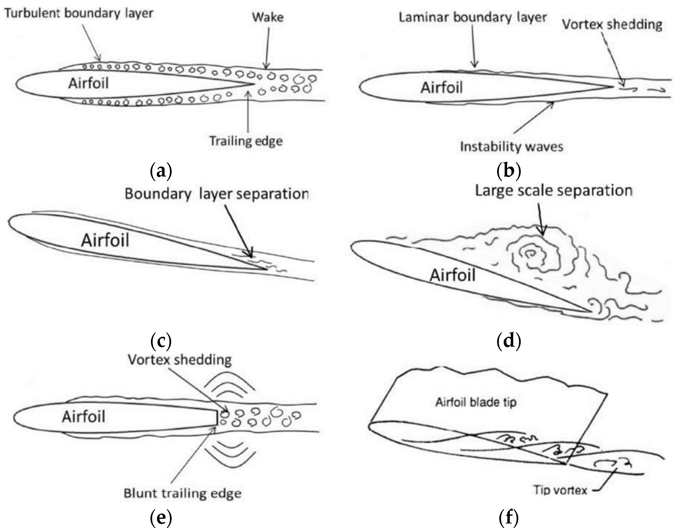
Figure 1. Six types of blade noise [20].
Energies 16 04331 g001
Figure 2. (a) Typical volute shells; (b) bionic volute shells [29].
Energies 16 04331 g002
Figure 3. The geometry of the bionic volute tongue.
Energies 16 04331 g003
Figure 4. (a–h) Eight types of the established bionic volute tongue [34].
Energies 16 04331 g004
Figure 5. Spiral shell and point data of shell cavity [35].
Energies 16 04331 g005
Figure 6. Velocity vector distribution of impeller section on same circumferential position with 50% blade height section [35].
Energies 16 04331 g006
Figure 7. (a) Non-smooth morphology with no leading edge; (b) smooth morphology with leading edge [41].
Energies 16 04331 g007
Figure 8. The geometry of a bionic blade surface [42].
Energies 16 04331 g008
Figure 9. The rotor with additional surface structure array [44].
Energies 16 04331 g009
Figure 10. The simulation results of the rotor with surface structures in different shapes and the prototype rotor [44].
Energies 16 04331 g010
Figure 11. Comparison of two impeller internal vortex structures [46].
Energies 16 04331 g011
Figure 12. Owl wings and feathers: (a) owl wing; (b) owl flanker; (c,d) definition of wing parameters; (e) close-up view on a feathered leaf [47].
Energies 16 04331 g012
Figure 13. Leading and trailing marginal feather shapes of owls [52].
Energies 16 04331 g013
Figure 14. Installation of flying bird fins in wind tunnel tests [58].
Energies 16 04331 g014
Figure 16. Comparison of a single octave and one-third spectrum results [69].
Energies 16 04331 g016
Figure 17. The geometry of centrifugal fans and blades [74].
Energies 16 04331 g017
Figure 18. The result of Vorticity contours in different spans of blades [74].
Energies 16 04331 g018
Figure 19. (a) Axial fan with straight leading edge; (b) axial fan with wavy leading edge [75].
Energies 16 04331 g019
Figure 20. Computational steps of tonal noise hybrid method.
Energies 16 04331 g020
Figure 21. Structure of the vortex at the leading edge of the wave [81].
Energies 16 04331 g021
Figure 22. Schematic diagram of the base blade and wave leading-edge static sub-blade [82].
Energies 16 04331 g022
Figure 23. The SPL spectra for the baseline (BL) and serrated airfoil at (a) different serration amplitudes (A/C), where the vertical dashed lines indicate the frequency bandwidth of the noise reduction (850 Hz < f < 3.5 kHz), and (b) different levels of Tu. The baseline LE and serrated LE are represented by the straight and dashed lines, respectively. Spectra corresponding to the different Tu levels are shifted by 0 dB,15 dB, and 30 dB [84].
Energies 16 04331 g023
Figure 24. Prediction of noise reduction based on Howe’s model [90].
Energies 16 04331 g024
Figure 25. Serrated trailing-edge surface flow swirl [96].
Energies 16 04331 g025
Figure 26. Parameters associated with a non-flat plate-type sawtooth geometry [97].
Energies 16 04331 g026
Figure 27. Three types of blades [100].
Energies 16 04331 g027
Figure 28. Comparison of noise spectrum between serrated trailing-edge airfoil and basic airfoil [100].
Energies 16 04331 g028
Figure 29. Distribution of vortex cores in the area of the trailing edge of the blade [101].
Energies 16 04331 g029
Table 1. Snail shell and spacer noise reduction study.
StructureBionic ObjectMethodAdvantageDisadvantageReferences
Volute tongueAsio otusExperiment
Simulation
Suitable for 600~2000 Hz frequency rangeLess effective in the high-frequency range[26]
ExperimentSuitable for 1000~4000 Hz frequency rangeLess effective in the low-frequency range[27]
Owl wingSimulationLower than the design flowOverall efficiency reduced[29]
OwlExperimentImproved under the BPF conditionIneffective in the low-frequency band[32]
Volute shapeAsio otus WingExperiment
Simulation
Optimized for design conditionsLess effective in small flow[34]
Mantis Shrimp grooveSimulationSuitable for high-frequency pressureOverall efficiency reduced[36]
ShellSimulationLow expansion ratio conditionsIneffective in high expansion ratio conditions[37]
Table 2. Noise reduction studies on non-smooth surfaces.
StructureBionic ObjectMethodAdvantageDisadvantageReferences
Non-smooth surfaceLong-eared OwlExperiment
Simulation
Suitable for 1000~4000 Hz frequency rangeLess effective in the high-frequency range [40]
Humpback and Otus bakkamoenaSimulationSuitable for higher Reynolds numberNot universal[43]
OwlExperimentOverall optimizedThe improvement is less than 5%[44]
Volute Shape interfaceSharkExperimentSuitable for 10~12 BPFIneffective in the high-frequency range[46]
Table 3. Noise-reduction studies on the bionic leading blade.
Structure Bionic Object MethodAdvantageDisadvantageReferences
Leading edgewavyExperiment
Simulation
Suitable for 2500~5000 Hz frequency rangeLess effective for the 0~500 Hz frequency range [47]
ExperimentSuitable for low Reynolds numberThe application range is limited.[49]
ExperimentSuitable for a certain critical frequencySlower as the serration length is increased[51]
ExperimentReduce noise radiation at all azimuthsMore intense phase variation[52]
sawtoothSimulationSuitable for volume flow rate from 1.5~2 rangeAffected by normalized inflow velocity[53]
ExperimentSuitable for wide-band noiseNot universal[54]
humpbackExperiment
Simulation
Optimized for wide-band noiseAffected by viscosity effects[82]
swept-back wingSimulationAOAs above 20°Worse in between α = 7° and 20°[84]
Table 4. Noise-reduction studies on the bionic trailing blade.
Structure Bionic ObjectMethodAdvantageDisadvantageReferences
Trailing edgesawtoothExperiment
Simulation
Suitable for the high-frequency rangeLess effective for the high-frequency range [86]
ExperimentSuitable for high Reynolds numberAffect the overall hydrodynamic field[87]
ExperimentSuitable for the high-frequency rangeLess effective in the high-frequency range[88]
humpbackExperimentLittle effect on efficiencyApplicable to specific models[93]
Cut-inTheory
Experiment
Edge inclined less than 45° to the mean flowLimited by finite Mach numbers[94]
ExperimentSuitable for 600~2000 Hz frequency rangeLess effective for 2000~5000 Hz frequency range[100]
Disclaimer/Publisher’s Note: The statements, opinions and data contained in all publications are solely those of the individual author(s) and contributor(s) and not of MDPI and/or the editor(s). MDPI and/or the editor(s) disclaim responsibility for any injury to people or property resulting from any ideas, methods, instructions or products referred to in the content.