Abstract
A metal fiber burner is proposed for structural thermal tests for the test model of hypersonic vehicles. In order to guide the design of the burner, we conduct Fluent simulations on a cylindrical metal fiber burner with a properly selected thermal diffusion model, a heat transfer model between the gas and solid phase, a radiation model with a metal porous media, and a gaseous combustion chemistry mechanism. After validating the simulation, the combustion and heating characteristics of the burner were further analyzed. The results show that under the condition of no specimen, when the firing rate increases from 120 kW/m to 240 KW/m, the maximum gas temperature and the downstream gas temperature of the metal fiber increase by 6.21% and 8.55%, respectively, the outer surface temperature of the metal fiber increases by 6.42%, and the stable gas temperature downstream of the metal fiber reaches the maximum value at an equivalence ratio of 1. After the specimen is added, the internal and downstream gas temperatures of the metal fiber are significantly reduced, while the upstream gas and outer surface temperatures of the metal fiber show no significant changes. When the specimen diameter changes from 139mm to 98mm, the gas temperature and fiber surface temperature change is small, while the surface heat flux of the specimen significantly increases from 12.7 KW to 22.7 KW. It can be seen that when designing the test parameters, the surface heat flux of the specimen can be adjusted by adjusting the distance between the combustion surface and the specimen.
1. Introduction
A metal fibre burner is a combustion device that uses metal fibers as the combustion adhesion surface material. The premixed fuel/air mixture flows towards the burner head and combusts on the surface layer of a metal fiber fabric with uniform permeability. Heat exchange occurs via radiation and convection heat-transfer mechanisms. This type of combustion and heat exchange gives the metal fibre burner its unique characteristics. Firstly, it exhibits excellent transient heating properties, low thermal inertia, fast heating and cooling, and precise temperature control. Additionally, this device achieves a high heating temperature, large adjustment range of combustible mixture mass flows, and strong adaptability to different test conditions. Under diverse combustion regimes, the combustion power density can vary from 100 kW/m to 10,000 kW/m. Through the optimization of burner operation parameters, variations in heating power density can be accommodated. Thirdly, the burner geometry can be flexible. The metallic surface is fabricated from metal fibers, with a diameter of 20∼40 μm, and is capable of being fashioned into a multiplicity of shapes with a robust shape memory, thereby enabling it to conform to the varying structural topologies of the test models.
Owing to its aforementioned advantages, metal fibre burners have attracted significant attention in the realm of energy dynamics research [1]. In this paper, a thermal testing methodology was developed based on the metal fibre burner, which presents a noval technical approach for simulating hypersonic aerodynamic thermal environments to address the intricate challenges of creating an thermal test environment of unsteady heating and non-uniform heat flux spatial distribution.
During the flight of hypersonic aircraft, surfaces of aircraft are exposed to severe aerodynamic heating, leading to a severe challenge to the structural strength. Therefore, it is necessary to assess the strength through ground experimental tests. At present, the techniques used for hypersonic aerodynamic thermal environment experimental tests include quartz lamp radiation heating, electric arc wind tunnels, and high-temperature gas wind tunnels. These techniques are highly adaptable to requirements such as having a high temperature, large size, and extended heating time [2,3,4]. However, the existing techniques also present certain limitations regarding non-uniform heat flux distribution and highly unsteady heating abilities. In contrast, the metal fibre burner is free from such limitations and could offer a suitable thermal environment for ground tests of hypersonic aircraft structure thermal assessment due to its good transient heating characteristic and structural adaptability.
The accuracy of metal fibre combustion heating tests depends on the precise management of heat flows. Therefore, accurate predictions of the heating characteristics of metal fibers during combustion are a key issue in the design and application of thermal testing systems. Recently, intensive theoretical and empirical studies were conducted on metal fibre burners [5,6,7], improving the understanding of the thermal properties and combustion products of metal fiber burners. However, numerical investigations into metal fiber burners were comparatively less developed due to modeling challenges.
Heat transfer models for combustion in porous media form the foundation for numerical investigations into metal fiber burners. Comprehensive numerical models of combustion heat transfer in porous media have been proposed, including the heat-resistance model, thermal diffusion model, heat transfer model between the gas and solid phase, radiation model and combustion chemistry mechanism. Bouma et al. [8] established a one-dimensional numerical model for a lean premixed combustion of methane in porous media based on a simplified reaction mechanism, and analyzed the influence of gas radiation on gas temperature and combustion products. Diamantis et al. [9] applied a numerical model of premixed combustion of methane in porous media to surface-stabilized combustion and submerged combustion, and obtained variations in gas temperature and combustion products under different conditions, which were in good agreement with the experimental results. Leonardi [10,11,12] summarized the numerical simulation methods for premixed combustion in porous media, and established a one-dimensional numerical model for metal fiber combustion using the GRI-Mech 2.1 mechanism. The model was used to simulate laminar premixed combustion, and a flat metal fiber combustion experimental system was set up to investigate the effects of factors such as equivalence ratio, combustion intensity, downstream oxygen content, surface radiation rate and solid thermal conductivity on the simulation results. The accuracy of the simulation calculations was verified by comparison with experimental data. Zhu et al. [13] used the EDC combustion model to obtain the combustion characteristics of the metal fiber porous medium region under blue flame conditions, considering flow resistance and turbulence correction. Garcia [14] evaluated three combustion models and five chemical kinetic mechanisms to compare their performance in the numerical simulation of the specific burner.
From previous studies, simulation based on treating metal fibers as porous media can accurately predict the temperature and concentration fields of combustion. However, less exploration has been conducted regarding the influence of thermal diffusion, heat transfer between the gas and solid phase, and thermal radiation on the simulation.
In this paper, a thermal test system based on the metal fiber burner is proposed for high-speed aircraft structural thermal assessment, and a numerical simulation of metal fiber combustion is conducted. A reasonable thermal diffusion model, heat transfer model between the gas and solid phases, porous media thermal radiation model, and combustion chemistry mechanism are selected. Using the selected models, the accuracy of the simulation is verified. We use this model to conduct a systematic analysis of the heating characteristics of a metal fiber burner and investigate the effects of the test piece on the combustion heating characteristics. Then, we analyze the combustion characteristics of a cylindrical radial metal fiber burner, and reveal the key parameters controlling the gas temperature field together with the influence of the test model on the combustion characteristics.
2. Thermal Test System Based on Metal Fiber Burner
The aerothermal load on the surface of high-speed aircraft presents the characteristics of a large gradient distribution, high-impact momentum, and strong nonlinearity [15,16], which raises new demands for aerothermal environment simulation methods. Firstly, the ability to simulate large gradient heat-flux distribution is required, which can form heat-flux differences on different areas of the structural surface. Secondly, the ability to simulate high-impact momentum and nonlinear time-varying heat fluxes is required, which can dynamically track and simulate the target heat flux throughout the whole trajectory. Thirdly, the ability to adapt to complex structural surfaces is required, which can load the surface heat flux of complex structures such as leading edges, flaps, intakes, and nozzles.
In order to meet the requirements for simulating the aerodynamic heating environment of hypersonic flight structural components, a thermal test system heated by a metal fiber burner is designed to generate high-temperature combustion gas jet to heat the structural scales. This system is capable of simulating a high-impact rate and non-linear time-varying thermal loads.
Figure 1 illustrates the schematic of the thermal test system, where methane and air are adjusted for flow and pressure before entering the metal fiber burner for premixed combustion to produce high-temperature combustion gas to heat the scale. During the test, the air–gas ratio is controlled by a proportional valve, and the gas flow is regulated by a flow controller with feedback adjustment of the measured test model temperature and surface heat flux in real-time. This mechanism enables the automatic tracking of the preset thermal load target value and the realization of a high-impact rate loading and non-linear time-varying thermal loads. The burner head can be shaped differently to meet the testing needs of test models with various geometries. Additionally, the burner surface can be designed with different zones to independently control the heating intensity according to different the surface heat flux requirements in different regions of the test model, thus achieving the simulation of heat flux gradients.
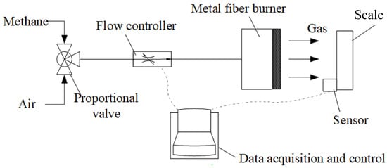
Figure 1.
Schematic of thermal test system heated by metal fiber burner.
3. Numerical Methods Research
3.1. Mathematical Model
3.1.1. Model Assumptions
The heat and mass transfer process of metal fiber combustion is complex. To simplify the calculations while ensuring computational accuracy, the following assumptions are made for the model:
- The laminar flame model is used [17].
- Gas radiation is neglected.
- The metal fiber porous medium is assumed to be an inert, optically thick, isotropic medium, and solid radiation is converted into an equivalent radiative conductivity.
- The gas is assumed to be an incompressible ideal gas.
- The solid phase and gas phase are in a non-thermal equilibrium state, and a two-temperature model is used.
- Gas thermal diffusion in the metal fiber porous medium is considered.
- Buoyancy effects of the gas are ignored.
3.1.2. The Governing Equations for Fluid Flow in Porous Media
Continuity equation:
where is the density of gas, measured in kg/m; is the velocity vector, measured in m/s; t is the time, measured in s.
Momentum equation:
where is the porosity of the porous medium; P is pressure, measured in Pa; is the dynamic viscosity, measured in Pa·s; represents the flow resistance term within the porous medium, which includes viscous and inertial resistance and can be expressed as [18,19]:
where K is the permeability of the porous medium; is the inertial resistance coefficient.
Gas energy equation:
where is the gas temperature, measured in K; is the specific heat capacity of the gas, measured in J/(kg·K); is the effective thermal conductivity of the gas, measured in W/(m·K); is the enthalpy value of the gas component i, measured in J/kmol; is the chemical reaction rate of the gas component i, expressed and measured in kmol/s; is the molar mass of the gas component i; is the number of gas components; is the volume-averaged convective heat transfer coefficient between the gas and solid phases in the porous medium, measured in W/(mK); is the solid temperature, measured in K.
Due to the gas thermal-diffusion effect, the effective thermal conductivity of gas is as follows:
where is the thermal diffusivity coefficient [20], is taken, where is the gas flow velocity, measured in m/s, and is the diameter of the metal fiber, measured in m.
Solid energy equation:
where represents the specific heat capacity of the solid, measured in J/(kg·K); is the density of the solid, expressed in kg/m; is the effective thermal conductivity of the solid, measured in W/(m·K).
Taking the radiative effect of the porous medium solid framework on heat transfer into account, the effective thermal conductivity of the solid is as follows:
where is the thermal conductivity of the metal fiber material, measured in W/(m·K); is the effective radiative thermal conductivity [21,22], and in this paper:
where is the Stefan-Boltzmann constant, measured in W/(mK); is the emissivity of the porous medium; l is the characteristic length, .
In Equations (4) and (6), the volume-averaged convective heat transfer coefficient [23] is denoted as:
where Pr represents the Prandtl number of the gas; Re is the Reynolds number.
The components’ transport equation is as follows:
where is the mass fraction of component i; denotes the density of component i, expressed in kg/m; is the mass diffusion coefficient of component i, measured in m/s; represents the chemical reaction source term.
The quality diffusion coefficient is calculated through the binary diffusion coefficient [24]:
where represents the molar fraction of component i, and denotes the binary diffusion coefficient.
The equation of state:
where P is the pressure; V is the volume; R is the gas constant; n represents the amount of gas substance; T represents the temperature of an ideal gas.
3.1.3. Combustion Model and Chemical Mechanism
The premixed gas with a low mass flow rate and laminar flow is used [12]; thus, this paper adopts a laminar finite-rate model for the chemical reaction. The reaction rate is calculated based on the Arrhenius formula, and the forward reaction rate constant is:
where is the pre-exponential factor; is the temperature exponent; T is temperature, measured in K; is the activation energy, measured in J/kmol; R is the gas constant, measured in J/(kmol·K).
For methane/air combustion, scholars have developed detailed mechanism models. This paper uses the GRI-Mech 1.2 chemical kinetics model, which has been extensively validated by experiments and widely recognized. The GRI-Mech 1.2 model includes 32 species and 177 elementary reactions, and simplifies the reaction mechanism on which this paper does not focus. By ensuring calculation accuracy, the calculation speed is improved [25].
3.2. Solution
Considering the variations in physical parameters with temperature, the specific heat capacity and thermal conductivity at constant pressure for each gas component are calculated using fitting functions of temperature.
During the solving process, the variation in thermophysical properties with temperature is considered. The specific heat at constant pressure, thermal conductivity, and dynamic viscosity are calculated using temperature-dependent fitting functions:
where F denotes the parameter values for specific heat at a constant pressure, as well as thermal conductivity, and dynamic viscosity of the gas; represents the polynomial coefficients. The GRI-Mech 1.2 model provides polynomial coefficient values for 32 species.
Gas density is calculated using the incompressible ideal gas model. Gas dynamic viscosity is calculated using kinetic theory [24].
The commercial software FLUENT (Version 19.0) is used to solve the problem. The gas thermal diffusion effect, heat transfer between gas and solid phase, and porous medium radiation model are incorporated into the numerical calculation model through User-Defined Functions (UDFs). The second-order upwind discretization scheme and the SIMPLE algorithm are employed to solve the problem. The gas temperature in the vicinity of the metal fiber is patched as 1800 K to simulate the ignition process. The calculation is performed using a Xeon E5-2650 processor with a clock speed of 2.3 GHz and a memory of 128 GB.
3.3. Model Validation
To validate the credibility of the numerical model proposed in this paper, a numerical validation of the combustion in the metal fiber burner presented in reference [10] is performed. A two-dimensional combustion model is developed, and the combustion intensity is defined as:
where is the chemical power input to the burner, measured in W; S is the surface area of the burner, measured in m.
The combustion intensity q and the equivalence ratio are important parameters that influence the combustion characteristics. The baseline condition is set to kW/m and . The boundary conditions and gas-solid parameters are consistent with the experimental and simulated parameters presented in reference [10]. The thickness of the metal fiber layer is set to 2 mm, and the temperature distribution of the gas and metal fiber layers is shown in Figure 2. Zone I represents the metal fiber area, and Zone II represents the outside of the metal fiber. From the figure, it can be seen that combustion of the premixed gas occurs in the metal fiber area, reaching the highest temperature. Due to the radiative cooling effect of the metal fiber surface, the downstream gas temperature is slightly lower than the highest temperature.
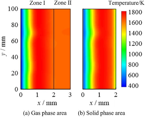
Figure 2.
Temperature contour on baseline condition.
The numerical calculation results are compared with the experimental results in this paper. As shown in Figure 3, the variation in the outlet gas temperature with q is observed under the rich combustion conditions with . It can be seen that the numerical calculation results and experimental results are in good agreement. The outlet gas temperature increases with the increase in q, and the relative error between the numerical calculation results and the experimental results of the outlet gas temperature does not exceed .
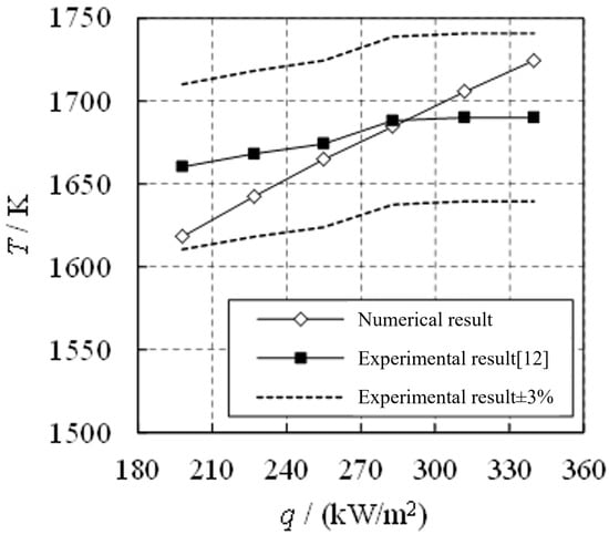
Figure 3.
Comparison between numerical and experimental data [12].
In addition, a comparison is made with the numerical calculation results in reference [10], and the distribution of gas temperature along the flow direction under the baseline operating condition is shown in Figure 4. This study obtained similar results to those in reference [10]. The maximum relative error in gas temperature in the metal fiber region (0 ≤ x ≤ 2 mm) does not exceed 10%, and the relative error in downstream gas temperature (2 mm ≤ x ≤ 3 mm) is relatively small, not exceeding 4.4%.
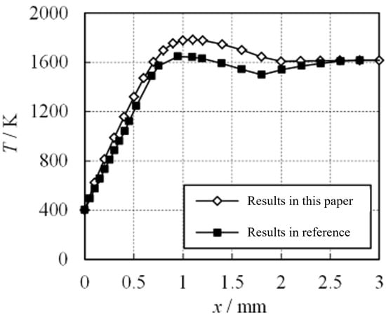
Figure 4.
Comparison between numerical data in this paper and numerical data in reference.
The above analysis indicates that the numerical model proposed in this paper has a high level of reliability.
4. Simulation Results
4.1. Physical Model
This paper focuses on a cylindrical metal fiber burner, as shown in Figure 5. The burner has an outer diameter of , a length of l, and a thickness of a, the gas flows radially (in the r-direction). The burner is coaxially placed inside a cylindrical test model with an inner diameter of . Methane/air premixed gas enters the head of the burner from the left side and burns on the cylindrical metal fiber surface, generating high-temperature gas that is ejected radially to heat the cylindrical test model. The metal fiber layer is made of alloy.
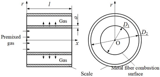
Figure 5.
Schematic of cylindrical metal fiber burner.
Under the baseline operating condition, the system parameter values are set as shown in Table 1.

Table 1.
Values of the system parameters under the baseline condition.
4.2. Experimental System Combustion Heating Characteristics’ Analysis
4.2.1. Baseline Operating Condition Analysis
The computational analysis was carried out on a two-dimensional mesh. To simplify the three-dimensional rotating body model investigated in this study, the Axisymmetric Solver was employed to transform it into a two-dimensional problem. Five sets of meshes were used to verify the mesh independence, with total numbers of nodes being 6000, 9000, 12,000, 16,000, and 22,000, respectively. The boundary conditions are as follows: the inlet temperature K, the outlet temperature (i.e., the ambient temperature) K, the atmospheric pressure 101,325 Pa. The baseline operating conditions were set to kW/m and .
The calculated results of the maximum gas temperature, maximum solid temperature of metal fibers, and gas flow velocity at the metal fiber surface (at x = 105 mm) with respect to the mesh size are illustrated in Figure 6. As shown in Figure 6, when the number of mesh nodes reached 12,000, further increasing the mesh size had little effect on the calculation results. Therefore, in this study, mesh 3 was selected for the calculation.
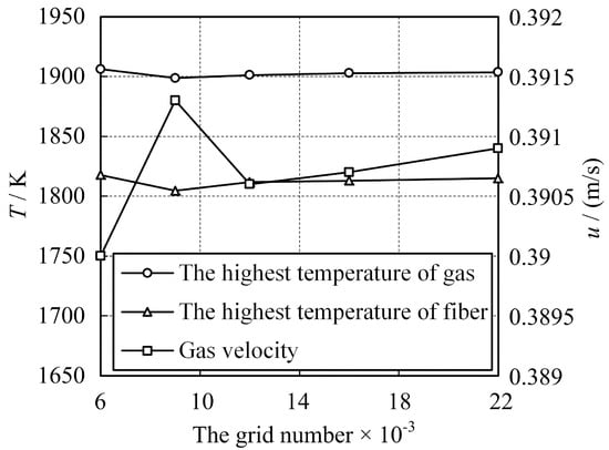
Figure 6.
The variations in the highest temperature of the gas, the highest temperature of fiber, and the gas velocity with respect to the number of grids.
Taking kW/m and as the baseline operating condition, the gas temperature distribution in the cylindrical burner under the baseline condition is shown in Figure 7, where mm is the inner surface of the metal fiber and mm is the outer surface. As can be seen from the figure, the gas rapidly heats up the metal fiber. Temperature reaches the maximum vaue inside the metal fiber, and slightly drops at the outer surface of the metal fiber. Then, the temperature reaches a stable value in the outside of the metal fiber.
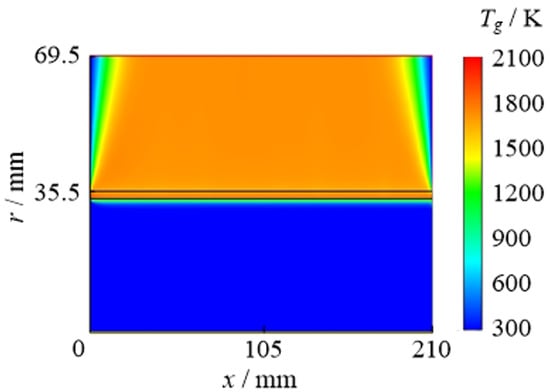
Figure 7.
Gas temperature contour of cylindrical metal fiber burner under baseline condition.
Figure 8 quantitatively describes the radial distribution of the gas temperature and solid temperature of the metal fiber at mm. Since the gas temperature changes little in the region of r < 30 mm and r > 45 mm, only the region of 30 ≤ r ≤ 45 mm is shown in the figure, which is the combustion zone of the premixed gas. As shown in the figure, the gas temperature reaches its maximum value of 1822 K at r = 34.2 mm, decreases to 1729 K at the outer surface of the metal fiber, and reaches a stable temperature of 1791 K downstream. The solid temperature of the metal fiber reaches its maximum value of 1746 K at r = 34.1 mm and decreases to 1206 K at its outer surface. Analysis shows that the premixed gas burns in the interior of the metal fiber layer to produce high-temperature combustion gas. The metal fiber layer radiates heat to the external environment, causing the solid temperature and gas temperature at the outer surface to decrease. However, the gas at the outer of the metal fiber that has not reacted completely continues to burn, causing the gas temperature to rise again. Since there is no radiation heat dissipation on the inner surface of the metal fiber, the temperature of the inner surface is significantly higher than that of the outer surface.
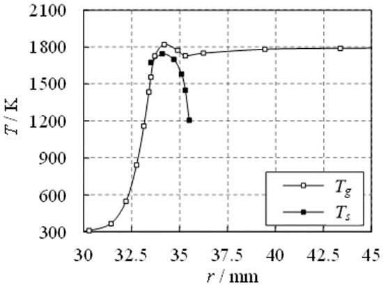
Figure 8.
Radial distributions of gas temperature and metal fiber temperature.
4.2.2. The Influence of Combustion Intensity on Temperature
Maintaining , simulations are performed for operating conditions with q values of 120, 160, 200, and 240 kW/m. Figure 9 presents the radial distribution of gas temperature at mm ( mm) for different operating conditions. The trend of radial variation of gas temperature remains the same for different operating conditions. As the combustion intensity increases from 120 kW/m to 240 kW/m, the maximum gas temperature and downstream gas temperature both gradually increase, with increments of 6.21% and 8.55%, respectively. Meanwhile, the upstream gas temperature is negatively correlated with the combustion intensity.
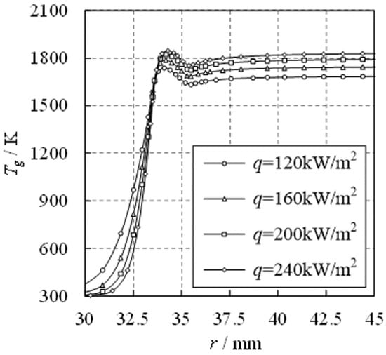
Figure 9.
Radial distributions of gas temperature.
Figure 10 shows the radial distribution of the solid temperature of the metal fiber at mm ( mm) under different operating conditions. It can be observed that the variation trend of metal fiber temperature along the radial direction is similar under different operating conditions. With the increase in combustion intensity from 120 kW/m to 240 kW/m, the maximum temperature and surface temperature of the metal fiber increase slightly. The maximum temperature increases by 5.87%, the inner surface temperature increases by 1.6%, and the outer surface temperature increases by 6.42%.
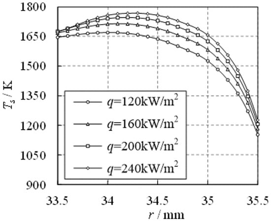
Figure 10.
Radial distributions of metal fiber temperature.
Based on the above analysis, to achieve higher test temperatures in the metal fiber combustion calorimeter, it is recommended to reasonably increase the gas flow rate, and thus increase the combustion intensity.
4.2.3. The Effect of Equivalence Ratio on Temperature
Maintaining kW/m, simulations are performed under different conditions of equivalence ratio at 0.9, 0.95, 1, 1.05, and 1.1. Figure 11 shows the variations in the maximum gas temperature, the downstream stable gas temperature, the highest fiber temperature, and the outer surface temperature of the fiber with respect to the equivalence ratio. As can be observed from the figure, the downstream stable gas temperature reaches its maximum value at . Under the conditions of lean and rich combustion, the downstream gas temperature is lower than that at , with a constant fuel flow rate. The variations in the maximum gas temperature, the highest temperature of the fiber, and the outer surface temperature of the fiber with respect to the equivalence ratio are relatively small. Based on the above analysis, in order to obtain higher experimental temperatures in the metal fiber combustion test system, it is recommended to maintain the equivalence ratio of combustion close to 1.
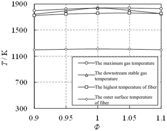
Figure 11.
Variation of temperature with equivalence ratio.
4.3. Analysis of the Effect of Test Models on Combustion Heating Characteristics
In addition to the characteristics of the burner itself, the presence of a test model can also affect the temperature field, and the distance between the combustion surface and the test model can affect the heat flux on the test model surface. Maintaining kW/m and , simulations were conducted for the heating cylinder test model under different internal diameter conditions to analyze the effect of the distance between the combustion surface and the test model on the heat flux on the test model surface.
4.3.1. The Influence of Test Models on Temperature
With a value of 123 mm and a test model surface temperature of 300 K, the temperature distribution of the burner gas was obtained as shown in Figure 12.
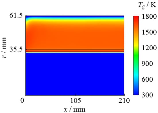
Figure 12.
Gas temperature contour when scale exists.
The conditions were compared with those without the scale. Figure 13 presents the radial distribution of gas and fiber temperatures. As indicated in the figure, the introduction of the cylindrical scale significantly reduces the gas temperature inside the metal fiber and the downsream gas temperature, while no significant difference is observed in the upstream gas temperature because of the partial absorption of gas heated by the scale wall. Additionally, it is observed that the downstream gas temperature maintains a stable temperature zone within the range of mm after the addition of the scale. Furthermore, because of the reduction in gas temperature, the solid temperature inside the metal fiber also exhibits a noticeable decrease, while the temperature change on the outer surface of the metal fiber is insignificant.
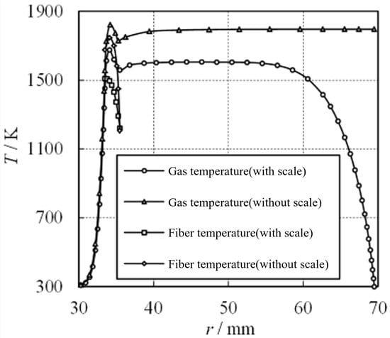
Figure 13.
Radial distributions of gas temperature and fiber temperature.
4.3.2. The Effect of Test Model Distance on Gas Temperature
Simulations are conducted for conditions with diameters of = 139, 123, 111, and 98 mm, and the radial distribution of gas temperature is obtained, as shown in Figure 14. Figure 14 shows that the gas temperature upstream and inside the metal fiber, as well as the downstream stable gas temperature, do not undergo significant changes as the distance between the combustion surface and the test model varies. Therefore, when designing a metal fiber heating test system, the effect of changes in test model position within a reasonable range on gas temperature can be disregarded.
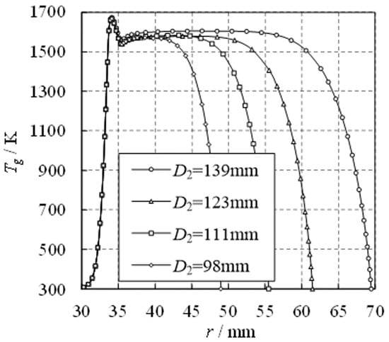
Figure 14.
Radial distributions of gas temperature when test model exists.
4.3.3. The Effect of Test Model Distance on the Surface Temperature of the Fiber
The fiber surface has a radiative heating effect on the test model; therefore, any change in the surface temperature of the fiber will directly affect the experimental heat flux.
Figure 15 shows the radial distribution of the solid temperature of the metal fiber under conditions with diameters of = 139, 123, 111, and 98 mm. Figure 15 shows that the internal and surface temperatures of the metal fiber did not undergo significant changes as the distance between the combustion surface and the test model varied. In particular, the curves for the = 123, 111, and 98 mm conditions essentially overlap. Therefore, when designing tametal fiber heating test system, the effect of changes in the test model position within a reasonable range on the surface temperature of the fiber can be disregarded.
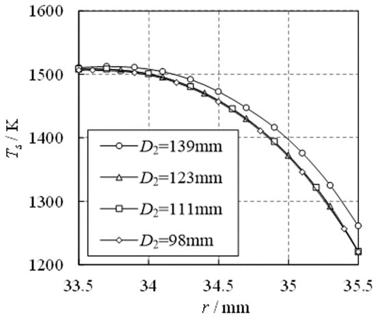
Figure 15.
Radial distributions of fiber temperature when test model exists.
4.3.4. The Effect of Test Model Distance on the Surface Heat Flux of the Test Model
As the effect of test model distance on the surface temperature of the fiber is minimal, changes in the surface heat flux of the test model are mainly due to variations in convective heat transfer. Figure 16 shows the distribution of convective heat flux on the test model surface under different conditions. Due to the presence of an unstable heat flux region at both ends of the test model, only values in the range of mm are displayed in the figure. Figure 16 shows that reducing the distance between the combustion surface and the test model can effectively enhance convective heat transfer, thereby increasing the surface heat flux of the test model. Moreover, under different conditions, the heat flux distribution in the region of mm is relatively uniform. Considering the heat flux at x = 105 mm, when decreases from 139 mm to 98 mm, that is, when the distance between the combustion surface and the test model is reduced from 34 mm to 13.5 mm, the convective heat flux on the test model surface increases from 12.7 kW to 22.7 kW. Based on the above characteristics, it can be concluded that the metal fiber combustion heating test system can produce a uniformly distributed heat flux on the surface of the test model. Furthermore, when designing the test parameters, the distance between the combustion surface and the test model can be reasonably adjusted to achieve the purpose of regulating the surface heat flux of the test model.
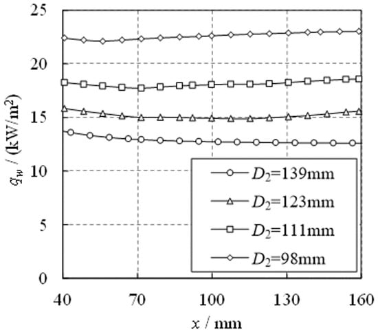
Figure 16.
Heat flux of convective heat transfer on the surface of test model.
5. Conclusions
This paper proposes a metal fiber combustion thermal testing system for the thermal assessment of high-speed aircraft structures and establishes a numerical simulation model for metal fiber combustion to verify its accuracy. A numerical simulation analysis of the combustion characteristics of a cylindrical radial metal fiber combustion head is conducted and the following conclusions are drawn:
- A reasonable gas thermal diffusion model, heat transfer model between the gas and solid phase, porous media radiation model, and combustion chemistry mechanism are selected, and the model is verified to have high reliability.
- The analysis of the combustion heating characteristics of the testing system reveals that when the combustion intensity and equivalence ratio change within a certain range, the highest gas temperature is reached inside the metal fiber and stabilized outside the metal fiber. To achieve a higher testing temperature in the metal fiber combustion thermal testing system, the gas flow rate should be reasonably increased to increase the combustion intensity and maintain an equivalence ratio close to 1.
- After the cylindrical test model is added, the gas temperature inside the metal fiber, downstream gas temperature, and solid temperature inside the metal fiber are significantly reduced compared to those without the test model, while the upstream gas temperature and the outer surface temperature of the metal fiber show no significant difference. The distance between the combustion surface and the scale have little effect on the gas temperature and fiber surface temperature but have a significant impact on the heat flow on the test piece surface.
In practical applications, the lift time or structure safety test of the thermal-resistant materials used in the real supersonic or hypersonic flights could easily be tested under the specified heat flux environment provided by the metal fiber burner. Further experiments based on the present study will be proposed. The temperature rang should be extended by changing the fuels and oxidizers to mimic the temperature environment for super-hypersonic flights.
Author Contributions
Conceptualization, R.W.; methodology, R.W. and R.A.; investigation, B.Q.; data curation, B.Q.; writing—original draft, B.Q. and Y.Z.; writing—review and editing, R.A. and S.D.; visualization, Y.Z.; supervision, R.W. and S.D.; project administration, S.D. All authors have read and agreed to the published version of the manuscript.
Funding
This research was funded by National Natural Science Foundation of China grant number 11902026.
Conflicts of Interest
The authors declare no conflict of interest.
Abbreviations
The following abbreviations are used in this manuscript:
| The density of gas | |
| The velocity vector | |
| t | Time |
| The porosity of the porous medium | |
| P | Pressure |
| Dynamic viscosity | |
| The flow resistance term within the porous medium | |
| K | The permeability of the porous medium |
| Inertial resistance coefficient | |
| The gas temperature | |
| The specific heat capacity of the gas | |
| The effective thermal conductivity of the gas | |
| The enthalpy value of gas component i | |
| The chemical reaction rate of gas component i | |
| The molar mass of gas component i | |
| The number of gas components | |
| The volume-averaged convective heat transfer coefficient | |
| The solid temperature | |
| Thermal diffusivity coefficient | |
| The gas flow velocity | |
| The diameter of the metal fiber | |
| The specific heat capacity of the solid | |
| The density of the solid | |
| The effective thermal conductivity of the solid | |
| The thermal conductivity of the metal fiber material | |
| The effective radiative thermal conductivity | |
| The Stefan-Boltzmann constant | |
| The emissivity of the porous medium | |
| l | The characteristic length |
| Pr | The Prandtl number of the gas |
| Re | Reynolds number |
| The mass fraction of component i | |
| The density of component i | |
| The mass diffusion coefficient of component i | |
| V | The volume |
| R | The gas constant |
| n | The amount of gas substance |
| T | The temperature of an ideal gas |
| The chemical reaction source term | |
| The molar fraction of component i | |
| The binary diffusion coefficient | |
| The pre-exponential factor | |
| The temperature exponent | |
| T | Temperature |
| The activation energy | |
| R | The gas constant |
| F | The parameter values for a specific heat at constant pressure |
| The polynomial coefficients | |
| The chemical power input to the burner | |
| S | The surface area of the burner |
| q | The combustion intensity |
| The equivalence ratio | |
| The outer diameter of the burner | |
| l | The length |
| a | The thickness |
| The inner diameter of the burner | |
| The solid temperature |
References
- Qiu, Z.; Li, P. Metal fiber burner and analysis of head resistance characteristics. J. Tongji Univ. Nat. Sci. 2005, 33, 217–220. [Google Scholar]
- Wu, D.; Zhou, A.; Zheng, L.; Pan, B.; Wang, Y. Thermal protection performances of metallic honeycomb panel structure at transient thermal shock environment. J. Aerosp. Power 2014, 29, 1261–1271. [Google Scholar]
- Hodge, J.; Harvin, S. Test capabilities and recent experiences in the NASA Langley 8-Foot High Temperature Tunnel. In Proceedings of the 21st Aerodynamic Measurement Technology and Ground Testing Conference, Denver, CO, USA, 19–22 June 2000; p. 2646. [Google Scholar]
- Morino, Y.; Caristia, S. Thermal responses of a large nose cap model tested at scirocco. In Proceedings of the 43rd AIAA Aerospace Sciences Meeting and Exhibit, Reno, NV, USA, 10–13 January 2005; p. 174. [Google Scholar]
- Golombok, M.; Prothero, A.; Shirvill, L.C.; Small, L. Surface combustion in metal fibre burners. Combust. Sci. Technol. 1991, 77, 203–223. [Google Scholar] [CrossRef]
- Saracco, G.; Sicardi, S.; Specchia, V.; Accornero, R.; Guiducci, M.; Tartaglino, M. On the Potential of Fibre Burners to Domestic Burners Applications—An Experimental Study; Gas Waerme International: Berlin, Germany, 1996; Volume 45. [Google Scholar]
- Marrecau, W.L.; Missoum, A.; Vansteenkiste, P.V. The knitted metal fiber burner: A new generation of surface combustion material for radiant heat and low NOx applications. ASHRAE Trans. 1998, 104, 721. [Google Scholar]
- Bouma, P.; De Goey, L. Premixed combustion on ceramic foam burners. Combust. Flame 1999, 119, 133–143. [Google Scholar] [CrossRef]
- Diamantis, D.; Mastorakos, E.; Goussis, D. Simulations of premixed combustion in porous media. Combust. Theory Model. 2002, 6, 383. [Google Scholar] [CrossRef]
- Leonardi, S.; Viskanta, R.; Gore, J. Analytical and experimental study of combustion and heat transfer in submerged flame metal fiber burners/heaters. J. Heat. Transf. 2003, 125, 118–125. [Google Scholar] [CrossRef]
- Leonardi, S.A. Partially-Premixed Combustion in Porous Radiant Burners. Ph.D. Thesis, Purdue University, West Lafayette, IN, USA, 2000. [Google Scholar]
- Leonardi, S.; Viskanta, R.; Gore, J. Radiation and thermal performance measurements of a metal fiber burner. J. Quant. Spectrosc. Radiat. Transf. 2002, 2, 491–501. [Google Scholar] [CrossRef]
- Zhu, R.; Pan, D.; Gao, H.; Gao, N.; Zhu, T. Simulation Study on surface combustion of metal fiber burner. Gas Heat 2020, 40, 36–43. [Google Scholar]
- Garcia, A.M.; Rendon, M.A.; Amell, A.A. Combustion model evaluation in a CFD simulation of a radiant-tube burner. Fuel 2020, 276, 118013. [Google Scholar] [CrossRef]
- Palmer, G.; Polsky, S. A heating analysis of the nosecap and leading edges of the X-34 vehicle. In Proceedings of the 36th AIAA Aerospace Sciences Meeting and Exhibit, Reno, NV, USA, 12–15 January 1998; p. 878. [Google Scholar]
- Prabhu, D.; Loomis, M.; Venkatapathy, E.; Polsky, S.; Papadopoulos, P.; Davies, C.; Henline, W. X-33 aerothermal environment simulations and aerothermodynamic design. In Proceedings of the 36th AIAA Aerospace Sciences Meeting and Exhibit, Reno, NV, USA, 12–15 January 1998; p. 868. [Google Scholar]
- de Lemos, M.; Pivem, A.; Dórea, F.; Tofaneli, L. Simulation of Turbulent Combustion in Porous Radiant Burners. In Proceedings of the 20th International Congress of Mechanical Engineering, Gramado, Brazil, 15–20 November 2009. [Google Scholar]
- Zhang, J.; Cheng, L.; Zheng, C.; Luo, Z.; Ni, M. Numerical studies on the inclined flame front break of filtration combustion in porous media. Energy Fuels 2013, 27, 4969–4976. [Google Scholar] [CrossRef]
- Malico, I.; Zhou, X.; Pereira, J. Two-dimensional numerical study of combustion and pollutants formation in porous burners. Combust. Sci. Technol. 2000, 152, 57–79. [Google Scholar] [CrossRef]
- Zheng, C.; Cheng, L.; Saveliev, A.; Luo, Z.; Cen, K. Numerical studies on flame inclination in porous media combustors. Int. J. Heat Mass Transf. 2011, 54, 3642–3649. [Google Scholar] [CrossRef]
- Liu, Y.; Fan, A.; Yao, H.; Liu, W. Numerical investigation of filtration gas combustion in a mesoscale combustor filled with inert fibrous porous medium. Int. J. Heat Mass Transf. 2015, 91, 18–26. [Google Scholar] [CrossRef]
- Yang, H.; Minaev, S.; Geynce, E.; Nakamura, H.; Maruta, K. Filtration combustion of methane in high-porosity micro-fibrous media. Combust. Sci. Technol. 2009, 181, 654–669. [Google Scholar] [CrossRef]
- Bubnovich, V.; Toledo, M. Analytical modelling of filtration combustion in inert porous media. Appl. Therm. Eng. 2007, 27, 1144–1149. [Google Scholar] [CrossRef]
- Zhou, Y.; Meng, S.; Xie, W.; Yang, Q. Multi-field coupling numerical analysis of aerothermal environment and structural heat transfer of hypersonic vehicles. Acta Aeronaut. Astronaut. Sin. 2016, 37, 2739–2748. [Google Scholar]
- Barra, A.J.; Ellzey, J.L. Heat recirculation and heat transfer in porous burners. Combust. Flame 2004, 137, 230–241. [Google Scholar] [CrossRef]
Disclaimer/Publisher’s Note: The statements, opinions and data contained in all publications are solely those of the individual author(s) and contributor(s) and not of MDPI and/or the editor(s). MDPI and/or the editor(s) disclaim responsibility for any injury to people or property resulting from any ideas, methods, instructions or products referred to in the content. |
© 2023 by the authors. Licensee MDPI, Basel, Switzerland. This article is an open access article distributed under the terms and conditions of the Creative Commons Attribution (CC BY) license (https://creativecommons.org/licenses/by/4.0/).